

Cub Cadet RZT 42 User Manual

OPERATOR’S MANUAL
RZT SERIES
TRACTOR
Model Number
RZT 42
w/42" Mower Deck
IMPORTANT: READ SAFETY RULES AND INSTRUCTIONS CAREFULLY
Warning:
covered, brush-covered or grass-covered land unless the engine’s exhaust system is equipped with a spark arrester meeting
applicable local or state laws (if any). If a spark arrester is used, it should be maintained in effective working order by the operator.
In the State of California the above is required by law (Section 4442 of the California Public Resources Code). Other states may have
similar laws. Federal laws apply on federal lands. A spark arrester for the muffler is available through your nearest engine authorized
service dealer or contact the service department, P.O. Box 361131 Cleveland, Ohio 44136-0019.
CUB CADET LLC P.O. BOX 361131 CLEVELAND, OHIO 44136-0019 [ www.cubcadet.com]
PRINTED IN U.S.A.
This unit is equipped with an internal combustion engine and should not be used on or near any unimproved forest-
FORM NO. 769-02748
(10/06)
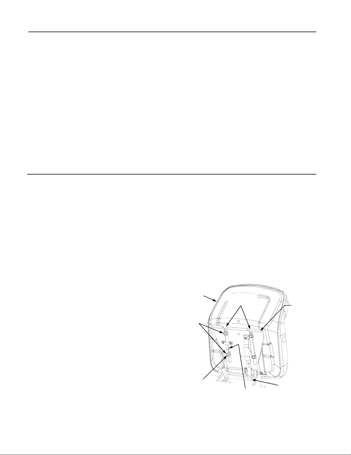
TABLE OF CONTENTS
TRACTOR PREPARATION .................................................................................................... 2
IMPORTANT SAFE OPERATION PRACTICES .................................................................... 4
SAFETY DECALS AND LABELS ........................................................................................... 7
SLOPE GAUGE ...................................................................................................................... 8
TO THE OWNER .................................................................................................................... 9
CALLING SERVICE INFORMATION ...................................................................................... 9
RECORDING MODEL AND SERIAL NUMBER INFORMATION ........................................... 9
SECTION 1: CONTROLS AND FEATURES ......................................................................... 10
SECTION 2: OPERATION .................................................................................................... 13
SECTION 3: ADJUSTMENTS .............................................................................................. 20
SECTION 4: MAINTENANCE ............................................................................................... 21
SECTION 5: MOWER DECK ................................................................................................ 28
WARRANTIES ...................................................................................................................... 34
TRACTOR PREPARATION
Remove the upper crating material from the shipping
pallet, and cut any bands or tie straps securing the tractor to the pallet.
Use the lift handle to raise the deck to its highest position; engage the transmission bypass rods (Refer to
SECTION 1, CONTROLS AND FEATURES); and carefully roll the tractor off the shipping pallet. Disengage the
bypass rods.
Remove the deck wash system nozzle adapter and oil
drain tube from the manual bag and store for future use.
INSTALL OPERATOR’S SEAT
The operator’s seat was partially inserted into the seat
pivot bracket for shipping purposes. To install the seat
proceed as follows:
1. Cut any straps securing the seat assembly and the
drive control levers to the tractor. Remove any
packing material.
NOTE: The seat is partially inserted into the slots of the
seat pivot bracket. If the seat does not become disengaged from the pivot bracket when removing the packaging material, the pivot bracket may be pivoted upward
and the seat pushed into place as described in step 6. If
the seat does disengage the pivot bracket, install the
seat as instructed in steps 2 through 6.
2. Pivot the seat pivot bracket partially upward. Refer
to Figure 1.
3. Note the grooves in the seat adjust spacers
attached to the bottom of the seat, then lift the seat
and position above and to the rear of the pivot
bracket.
4. Align the grooves in the seat adjust spacers with
the sides of the adjustment slots in the pivot
bracket.
5. Slide the seat adjust spacers into the slots of the
pivot bracket.
6. Continue to push the seat forward in the pivot
bracket until the front/left shoulder bolt of the seat
assembly passes forward of the stop bracket on
the seat pivot bracket. See Figure 1.
Use the seat adjust lever to adjust the seat position. Refer to "Adjusting the Operator’s Seat" in Section 3 for
seat adjustment instructions.
Seat
Seat
Adjust
Spacer
Front/Left
Shoulder Bolt
Adjustment
Slots
Stop Bracket
Figure 1
Seat
Pivot
Bracket
Seat Adjust
Lever
2
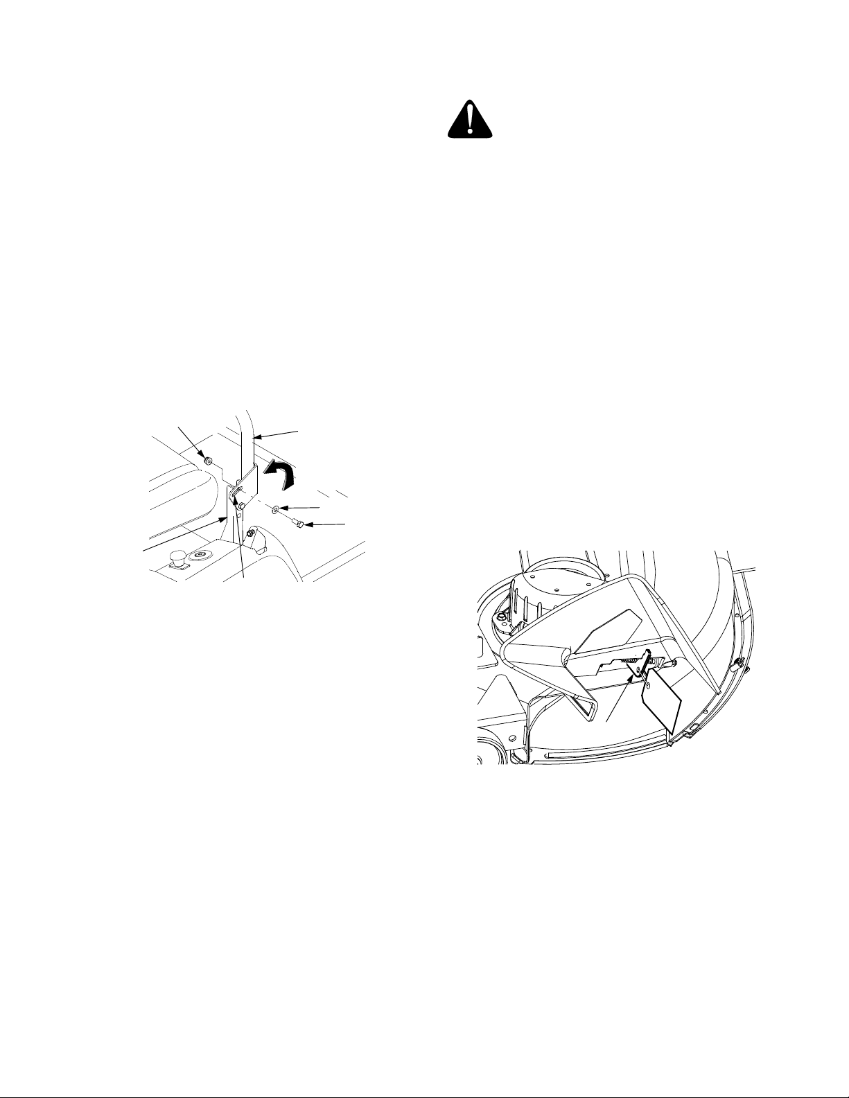
POSITION DRIVE CONTROL LEVERS
The drive control levers of the tractor are lowered for
shipping purposes. To accomplish this, the flange lock
nut, hex screw, and flat washer normally used to secure
each control lever to its pivot bracket are removed. The
hardware is then installed in the slotted hole of each
control lever for shipment. The control levers must be
moved to their operating position. To reposition the control levers for operation, proceed as follows:
• Remove the hex screw, flat washer, and flange lock
nut from the slot of one of the drive control levers.
• Lift and swing that control lever upward until the
slotted hole in the lever bracket aligns with one of
the holes in the pivot bracket. Refer to Figure 2.
• Slide the flat washer onto the hex screw. From the
outside, insert the hex screw w/washer through the
control lever slot and the hole of the pivot bracket.
Secure with the flange lock nut. See Figure 2.
CONNECT THE BATTERY
WARNING: Battery posts, terminals and
related accessories contain lead and lead
compounds. Wash hands after handling.
The tractor is shipped with an activated sealed battery,
with the positive battery cable factory connected. The
negative cable must be connected.
NOTE: Make sure the ignition switch is in the "OFF" position before attaching the battery cable.
1. Pull the protective cap, if present, off the negative
terminal of the battery, and remove the hex cap
screw and nut from the free end of the negative battery cable.
2. Connect the negative battery cable (heavy black)
to negative terminal (NEG) of the battery using the
hex cap screw and nut. Slide the black terminal
cover, if present, over the negative terminal of the
battery.
Flange Lock Nut
Control Lever
Lift control
lever upward
Flat Washer
Hex Screw
Pivot
Bracket
Slotted
Hole
Figure 2
• Note the relative position of the control lever to the
pivot bracket, then repeat the previous steps to
reposition the other control lever in approximately
the same position.
• Refer to "Adjusting the Drive Control Levers" in
Section 3 for instructions on final adjustment of the
levers.
REMOVE THE CHUTE STOP
• Locate the chute stop on the right side of the
mower, between discharge chute and cutting deck.
• While holding the discharge chute up, rotate the
chute stop clockwise and remove.
• Discard the chute stop.
Chute Stop
Figure 3
3

WARNING
• The engine exhaust, some of its constituents, and certain vehicle components contain or emit chemicals known
to the State of California to cause cancer, birth defects or other reproductive harm.
• This unit is equipped with an internal combustion engine and should not be used on or near any unimproved
forest-covered, brush-covered, or grass-covered land unless the engine’s exhaust system is equipped with a
spark arrester meeting applicable local or state laws (if any). If a spark arrester is used, it should be maintained
in effective working order by the operator.
• In the State of California, the above is required by law (Section 4442 of the California Public Resources Code).
Other States may have similar laws. Federal laws apply to federal lands. A spark arrester muffler is available
at your nearest engine authorized service center.
IMPORTANT
THIS SYMBOL POINTS OUT IMPORTANT SAFETY INSTRUCTIONS WHICH, IF NOT FOLLOWED,
COULD ENDANGER THE PERSONAL SAFETY AND/OR PROPERTY OF YOURSELF AND
OTHERS. READ AND FOLLOW ALL INSTRUCTIONS IN THIS MANUAL BEFORE ATTEMPTING
TO OPERATE YOUR UNIT. FAILURE TO COMPLY WITH THESE INSTRUCTIONS MAY RESULT
IN PERSONAL INJURY. WHEN YOU SEE THIS SYMBOL— HEED ITS WARNING.
Your lawn mower was built to be operated according to the rules for safe operation
in this manual. As with any type of power equipment, carelessness or error on the
DANGER
I. GENERAL OPERATION
1. Read, understand and follow all instructions in the
manual and on the machine before starting. Keep
this manual in a safe place for future and regular
reference.
2. Only allow responsible individuals familiar with
the instructions to operate the machine. Know the
controls and how to stop the machine quickly.
3. Do not put hands or feet under the cutting deck or
near rotating parts.
4. Clear the area of objects such as rocks, toys,
wire, etc. which could be picked up and thrown by
the blades. A small object may have been
overlooked and could be accidentally thrown by
the mower in any direction and cause injury to
you or a bystander. To help avoid a thrown
objects injury, keep children, animals, bystanders
and helpers at least 75 feet from the mower while
it is in operation. Always wear safety glasses with
side shields or safety goggles during operation or
while performing an adjustment or repair, to
protect eyes from foreign objects. Stop the blades
when crossing gravel drives, walks or roads.
part of the operator can result in injury. This lawn mower is capable of amputating
hands and feet or throwing objects. Failure to observe the following safety
instructions could result in serious injury or death.
SAFE OPERATION PRACTICES
5. Be sure the area is clear of other people before
mowing. Stop machine if anyone enters the area.
6. Never carry passengers.
7. Disengage the blades before shifting into reverse
and backing up. Always look down and behind
before and while backing.
8. Be aware of the mower and attachment discharge
direction and do not point it at anyone. Do not
operate the mower without either the entire grass
catcher or the chute guard in place.
9. Slow down before turning. Operate the machine
smoothly. Avoid erratic operation and excessive
speed.
10. Never leave a running machine unattended.
Always turn off the blades, place the transmission
in neutral, set the parking brake, stop the engine
and remove key before dismounting.
11. Turn off blades when not mowing.
12. Stop the engine and wait until the blades come to
a complete stop before (a) removing the grass
catcher or unclogging chute, or (b) making any
repairs, adjusting or removing any grass or debris.
4

13. Mow only in daylight or good artificial light.
14. Do not operate the machine while under the
influence of alcohol or drugs.
15. Watch for traffic when operating near or crossing
roadways.
16. Use extra care when loading or unloading the
machine into a trailer or truck. This unit should not
be driven up or down a ramp onto a trailer or truck
under power, because the unit could tip over
causing serious personal injury. The unit must be
pushed manually on a ramp to load or unload
properly.
17. Never make a cutting height adjustment while the
engine is running if the operator must dismount to
do so.
18. Wear sturdy, rough-soled work shoes and closefitting slacks and shirts. Do not wear loose fitting
clothes or jewelry. They can be caught in moving
parts. Never operate a unit in bare feet, sandals
or sneakers.
19. Check overhead clearance carefully before driving
under power lines, wires, bridges or low hanging
tree branches, before entering or leaving
buildings, or in any other situation where the
operator may be struck or pulled from the unit,
which could result in serious injury.
20. Disengage all attachment clutches, set the
parking brake in the on position, and put the lap
bars to the neutral or out position before
attempting to start the engine.
21. Your mower is designed to cut normal residential
grass of a height no more than 10”. Do not
attempt to mow through unusually tall, dry grass
(e.g. pasture) or piles of dry leaves. Debris may
build up on the mower deck or contact the engine
exhaust presenting a potential fire hazard.
22. Use only accessories approved for this machine
by Cub Cadet. Read, understand and follow all
instructions provided with the approved
accessory.
II. SLOPE OPERATION
Slopes are a major factor related to loss of control and
tip-over accidents, which can result in severe injury or
death. All slopes require extra caution. If you cannot
back up the slope or if you feel uneasy on it, do not
mow it.
For your safety, use the slope gauge included as part
of this manual to measure slopes before operating this
unit on a sloped or hilly area. If the slope is greater
than 15° as shown on the slope gauge, do not operate
this unit on that area or serious injury could result.
DO:
Mow across slopes, not up and down.
Keep all movement on the slopes slow and gradual.
Do not make sudden changes in speed or direction.
Rapid acceleration or deceleration could cause the
front of the machine to lift and rapidly flip over backwards, which could cause serious injury.
Avoid starting or stopping on a slope. If the tires are
unable to maintain traction, disengage the blades and
proceed slowly and carefully straight down the slope.
Do not mow the slope until able to maintain traction.
Use slow speed. Choose a low enough speed so that
you will not have to stop while on the slope.
Remove obstacles such as rocks, limbs, etc.
Watch for holes, ruts or bumps. Uneven terrain could
overturn the machine. Tall grass can hide obstacles.
Follow the manufacturer’s recommendations for counterweights with attachments to improve stability.
Use extra care with grass catchers or other attachments. These can change the stability of the machine.
DO NOT:
Do not turn on slopes unless necessary; then turn
slowly and use extra care while turning.
Do not mow near drop-offs, ditches or embankments.
The mower could suddenly turn over if a wheel is over
the edge of a cliff or ditch, or if an edge caves in.
Do not mow on wet grass. Reduced traction could
cause sliding.
Do not try to stabilize the machine by putting your foot
on the ground.
Do not use the grass catcher on steep slopes.
III. CHILDREN
Tragic accidents can occur if the operator is not alert
to the presence of children. Children are often
attracted to the machine and the mowing activity.
Never assume that children will remain where you
last saw them.
1. Keep children out of the mowing area and in
watchful care of an adult other than the operator.
2. Be alert and turn the machine off if children enter
the area.
3. Before and when backing up, look behind and
down for small children.
4. Never carry children, even with the blades off.
They may fall off and be seriously injured or may
interfere with safe machine operation.
5

5. Never allow children under 14 years old to
operate the machine. Children 14 years and over
should only operate the machine under close
parental supervision and proper instruction.
6. Use extra care when approaching blind corners,
shrubs, trees or other objects that may obscure
your vision of a child or other hazard.
7. Remove the key when the machine is left
unattended to prevent unauthorized operation.
IV. SERVICE
1. Use extreme care in handling gasoline and other
fuels. They are extremely flammable and the
vapors are explosive.
a. Use only an approved container.
b. Never remove fuel cap or add fuel with the en-
gine running. Allow the engine to cool at least
two minutes before refueling.
c. Replace the fuel cap securely and wipe off any
spilled fuel before starting the engine as it may
cause a fire or explosion.
d. Extinguish all cigarettes, cigars, pipes and oth-
er sources of ignition.
e. Never refuel the machine indoors because fuel
vapors will accumulate in the area.
f. Never store the fuel container or machine
inside where there is an open flame or spark,
such as a gas hot water heater, space heater
or furnace.
2. Never run a machine inside a closed area.
3. To reduce fire hazard, keep the machine free of
grass, leaves or other debris build-up. Clean up
oil or fuel spillage. Allow the machine to cool at
least 5 minutes before storing.
4. Before cleaning, repairing or inspecting, make
certain the blade and all moving parts have
stopped. Disconnect the spark plug wire, and
keep the wire away from the spark plug to prevent
accidental starting.
5. Check the blade and engine mounting bolts at frequent intervals for proper tightness. Also visually
inspect blades for damage (e.g., excessive wear,
bent, cracked). Replace with blades which meet
original equipment specifications.
6. Keep all nuts, bolts and screws tight to be sure
the equipment is in safe working condition.
7. Never tamper with safety devices. Check their
proper operation regularly. Use all guards as
instructed in this manual.
8. After striking a foreign object, stop the engine,
remove the wire from the spark plug and
thoroughly inspect the mower for any damage.
Repair the damage before restarting and
operating the mower.
9. Grass catcher components are subject to wear,
damage and deterioration, which could expose
moving parts or allow objects to be thrown. For
your safety protection, frequently check the
components and replace with manufacturer’s
recommended parts when necessary.
10. Mower blades are sharp and can cut. Wrap the
blades or wear gloves, and use extra caution
when servicing blades.
11. Check the park brake operation frequently. Adjust
and service as required.
12. Muffler, engine and belt guards become hot
during operation and can cause a burn. Allow to
cool down before touching.
13. Do not change the engine governor settings or
overspeed the engine. Excessive engine speeds
are dangerous.
14. Observe proper disposal laws and regulations.
Improper disposal of fluids and materials can
harm the environment and the ecology.
a. Prior to disposal, contact your local
Environmental Protection Agency to
determine the proper method for disposing of
the waste. Recycling centers are established
to properly dispose of materials in an
environmentally safe fashion.
b. Use proper containers when draining fluids.
Do not use food or beverage containers that
may mislead someone into drinking from
them. Properly dispose of the containers immediately following the draining of fluids.
c. DO NOT pour oil or other fluids into the
ground, down a drain or into a stream, pond,
lake, or other body of water. Observe Environmental Protection Agency regulations when
disposing of oil, fuel, coolant, brake fluid, filters, batteries, tires and other harmful waste.
15. With the exception of utilizing the deck wash
feature, we do not recommend the use of a
pressure washer or garden hose to clean your
tractor. Water may cause damage to electrical
components; pulleys; bearings; or the engine.
The use of water will result in shortened life and
reduce serviceability.
WARNING - YOUR RESPONSIBILITY: Restrict the use of this power machine to persons who
read, understand and follow the warnings and instructions in this manual and on the machine.
6

SAFETY DECALS AND LABELS
Keep product safety graphics (decals) clean. Replace any safety graphic that is damaged, destroyed, missing, painted over or can no longer be read. Replacement safety graphics are available through your dealer.
N
METER MINDER
Every 50 Hours of Use a
“Change Oil” Message
Will Flash On The Display
For 2 Minutes Every
Time The Tractor Is
Started.
Follow The Oil
Change Intervals
Provided In The
Engine Manual.
TRA
T
S
T
C
U
R
T
S
NI
LIO
.TT
A
B
01/
1
SR
U
O
H
KR
AP
/ OTP
E
K
A
R
B
E
D
A
L
B
B
KR
A
P
,
TRATS
o
T •
O
ni
h
c
t
iw
s
.O.T.P
•
GNI
RTUEN
n
i s
r
ab
pa
L
•
S
NOI
r
p
tes el
tt
orhT
•"d
t
,
N
O
o
t
ye
k n
r
uT •snu
START
FORWARD
.
a
erA n
e
t
e
s
e
b
t
su
m EKA
R
n
o
i
t
isop )nw
o
d
( F
F
d
ra
w
tuo
d
na
L
A
is
op
EK
O
H
C
,
ylrepo
hw
e
sa
e
ler
,
TR
A
T
S neh
T
SRI
F
ROF
s
noi
ti
s
op
R
EP
O
lo
c
"
fi
no
i
t
r
e
nigne n
e
pO
,talF
A
n
I
f
f
O tra
t
S
•
.
yawA s
r
edn
a
t
s
y
B
p
eeK
•
E
MIT
S
R
OTA
.
d
e
epS
w
o
L
A t
A
elt
t
or
h
T teS
•
i
tc
a
r
P
•
,tfeL
,
e
s
r
e
v
eR ,
d
r
aw
r
o
F
(
,gni
r
e
v
uenaM ec
.degagnE
kc
e
D tuohtiW
)t
hgiR
NEUTRAL
REVERSE
OTICE
PTO Automatically
•
Disengages When
Both Lap Bars Are
Moved Into Reverse.
PTO Automatically
•
Reengages When
Levers Are Returned
T
o The Neutral
Or For
ward Positions.
GENERAL SAFETY INSTRUCTIONS
– LOCATED ON LEFT CONSOLE
ASIDE OPERATOR’S SEAT
• Do not allow operation by untrained personnel.
• Wait for all movement to stop.
• Place speed controls in neutral and set parking brake.
• Disengage implement drive.
• Before leaving operator's position:
• Stop engine, disconnect spark plug before adjusting or servicing.
• Do not add fuel while the engine is hot or running.
Weight Included With Bagger Must Be Installed.
• When Using The Optional Grass Bagging Attachment, The Front Counter
Engage Parking Brake, Shut Off And Remove Key.
• Before Leaving Operator Position, Disengage Blades, Place In Neutral,
• Be Sure Blades And Engine Are Stopped Before Placing Hands Or Feet Near Blades.
AVOID SERIOUS INJURY OR DEATH
GENERAL SAFETY INSTRUCTIONS
WARNING – LOCATED IN CENTER
OF SEAT BOX FRAME
TO REDUCE THE RISK OF INJU RY, DO NOT
UNLESS DISCHARGE COVER OR
OPERATE
GRASS CATCHER IS IN ITS PROPE R PLACE.
IF
DAMAGED, REPLACE IMMEDIATEL Y.
GENERAL OPERATING INSTRUCTIONS
– LOCATED ON RIGHT CONSOLE
ASIDE OPERATOR’S SEAT
ON
CHOKE
• Know Location And Function Of All Controls.
• Do Not Operate Unit Where It Could Slip Or Tip.
• Remove Objects That Could Be Thrown By The Blade.
And Working.
• Keep Safety Devices (Guards, Shields, Switches, Etc.) In Place
• Look Down And Behind Before And While Backing.
• Never Carry Children Even With Blades Off.
• Do Not Mow When Children Or Others Are Around.
• Avoid Sudden Turns.
• If Machine Stops Going Uphill, Stop Blade And Back Down Slowly.
• Go Across Slopes, Not Up And Down.
• Read The Operator's Manual.
WARNING
FAST
BRAKE
PAR
K
P
SLOW
OFF
THROTTLE CONTROL
DECK HEIGHT
INDICATOR
INDICATOR
PARK BRAKE
INDICATOR
HANDS AND FEET
SAFETY GRAPHIC
MOWER DECK
SAFETY GRAPHIC
MOWER DECK
SAFETY GRAPHIC
MOWER DECK
INFORMATION GRAPHIC
7
(Keep this sheet in a safe place for future reference.)
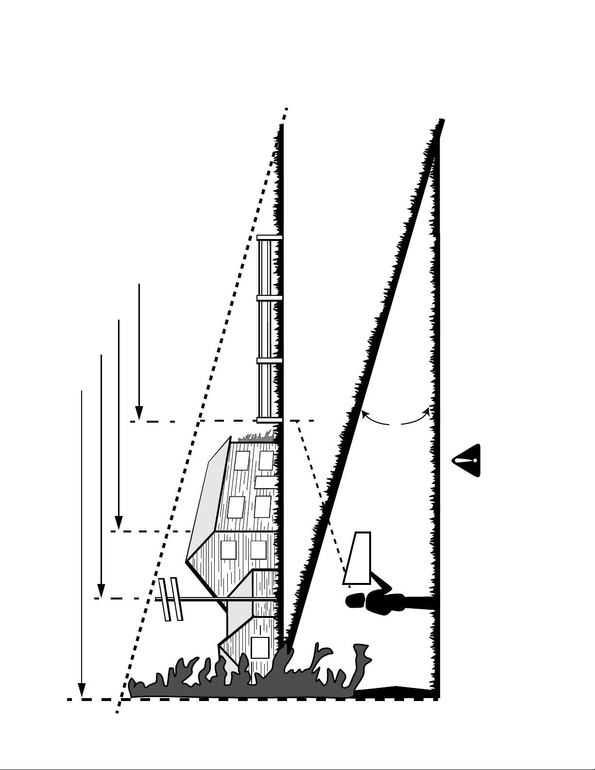
A CORNER OF A BUILDING
A POWER POLE
SIGHT AND HOLD THIS LEVEL WITH A VERTICAL TREE
SLOPE GAUGE
E
OP
SL
°
E
P
E
R
T
N
SE
N
I
A
G
5
1
OR A FENCE POST
R
,
E
N
I
L
D
E
T
T
O
D
15°
WARNING
ON
D
L
O
F
USE THIS PAGE AS A GUIDE TO DETERMINE SLOPES WHERE YOU MAY NOT OPERATE SAFELY.
Do not mow on inclines with a slope in excess of 15 degrees (a rise of approximately 2-1/2 feet every 10 feet).
A riding mower could overturn and cause serious injury. If operating a walk-behind mower on such a slope, it is
extremely difficult to maintain your footing and you could slip, resulting in serious injury.
Operate RZT zero turn tractors across the face of slopes rather than up and down. Begin with the first pass
across the bottom of the slope and turn uphill at the end of each pass whenever possible.
8

TO THE OWNER
This Operator’s Manual is an important part of your new tractor. The information contained in this manual has been
prepared in detail to help you better understand the features, correct operation, adjustments, and maintenance of
your tractor. The performance and dependability of this tractor rely greatly on the manner in which it is operated and
maintained. Therefore, it is recommended that all operators of the tractor carefully read this manual and fully understand its operation. Also keep the manual available for reference to ensure proper operation, and that maintenance
procedures are performed as scheduled to assure the tractor’s optimal mechanical condition.
NOTE: All references to LEFT, RIGHT, FRONT, and REAR, unless specifically stated otherwise, indicate that rela-
tive position on the tractor when facing forward while seated in the operator’s seat.
CAUTION: DO NOT tow your Model RZT42 tractor. Towing may damage the transmissions. Place the tractor on a
LEVEL SURFACE before pulling the transmission bypass rods to the engaged position (transmission disengaged).
Your local authorized Cub Cadet dealer is interested in the performance you receive from your tractor, and with the
maintenance needed to ensure the satisfactory operation of your tractor. The dealer has trained service personnel
familiar with the latest servicing information, is equipped with the latest tools, and has a complete line of genuine
Cub Cadet service parts which assure proper fit and high quality.
CALLING SERVICE INFORMATION
The engine manufacturer is responsible for all engine-related issues with regards to performance, power-rating, and
specifications.
If you have difficulties with the tractor and/or equipment; have any questions regarding the operation or maintenance
of this equipment; or desire additional information not found in this manual, contact your nearest authorized Cub
Cadet dealer. If you need assistance in locating a dealer in your area, contact the Customer Dealer Referral Line by
calling:
1-877-282-8684
Or you may contact Cub Cadet via the internet by logging on to our Web Site at:
www.cubcadet.com
To obtain top performance and assure economical operation, the tractor should be inspected by your authorized
dealer periodically or at least once a year, depending on its hours of use. Before calling your dealer, make sure that
you have your model number(s) and manufacturing date available for the dealer.
RECORDING MODEL AND SERIAL NUMBER INFORMATION
Product identification plates are provided for major components of your tractor. The numbers on these plates are
important if your tractor should require dealer service, or if you need additional information on your tractor. Prior to
using your tractor for the first time, record the numbers from the identification plates in the appropriate spaces provided below.
The chassis model plate, showing the factory model number and Mfg. Date (See Figure 4) can be found either on
the underside of the seat mounting base or on the right frame rail near the right front tire.
The engine information appear on a decal affixed to the engine shrouding (See Figure 5).
Model Factory Model No. Mfg. Date
Delivery Date Engine Model/Spec No. Engine Serial No.
XXXXXXXXXXX XXXXXXXXXX
Model Number Mfg. Date
CUB CADET LLC
www.cubcadet.com
DEALER LOCATOR PHONE NUMBER:
P. O. BOX
CLEVELAND, OH 44136
Figure 4 Figure 5
361131
877-282-8684
9
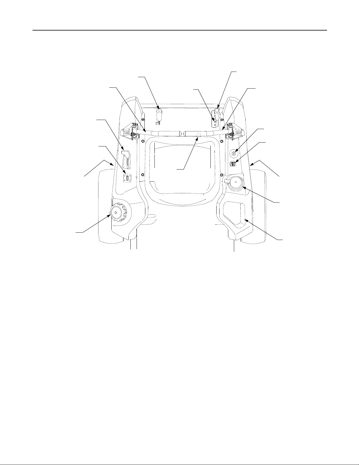
SECTION 1: CONTROLS AND FEATURES
N
C
M
L
F
K
A
J
B
C
D
E
F
G
H
A.
B.
Deck Lift Handle
C.
RH and LH Drive Control Levers
D.
Ignition Switch
E.
PTO Switch
F.
Transmission Bypass Rod (Not Shown)
G. Cup Holder
Figure 6
H.Deck Height Index
J.
K.
L.
M.
N.
10
Storage Tray
Seat Adjustment Lever (Not Seen)
Fuel Tank Cap
Hour Meter / Indicator Panel
Throttle Control
Parking Brake Engagement Lever

NOTE: References to LEFT, RIGHT, FRONT, and
REAR indicate that position on the tractor when
facing forward while seated in the operator’s seat.
A. Deck Height Index
The deck height index consists of six index notches
located on the front/right of the seat box frame. Each
notch corresponds to a 1/2 inch change in the deck
height position ranging from 1-1/2 inches at the lowest notch to 4 inches at the highest notch.
B. Deck Lift Handle
The deck lift handle is located on the front/right of the
seat box frame, and is used to raise and lower the
mower deck.
Pull the handle to the left out of the index notch and
push downward to lower the deck, or pull upward to
raise the deck. When the desired height is attained,
move the lift handle to the right until fully in the index
notch.
C. RH and LH Drive Control Levers
The RH and LH control levers are located on each
side of the operator’s seat. These hinged levers pivot
outward to open space to permit the operator to either
sit in the tractor seat, or to dismount the tractor. The
levers must be fully opened out and in the neutral
position to start the tractor engine.
Each lever controls the respective RH or LH transmission. Consequently, these levers control all of the
movements of the tractor. Driving and steering utilizing these control levers is quite different from
conventional tractors, and will take some practice to
master. Refer to SECTION 2: OPERATION for
instructions on using the control levers.
D. Ignition Switch
The ignition switch is located on the RH console to
the right of the operator’s seat.
The ignition switch has three positions as follow:
OFF
STOP
ON
START
E. Power Take-Off (PTO) Switch
The PTO switch is located on the RH console to the
right of the operator’s seat.
Figure 8
The PTO switch operates the electric PTO clutch
mounted on the bottom of the engine crankshaft. Pull
the switch knob upward to engage the PTO clutch, or
push the knob downward to disengage the clutch.
The PTO switch must be in the "disengaged" position
when starting the engine.
F. Transmission Bypass Rods (Not Seen)
The transmission bypass rods (one for each the RH
and LH transmission) are located beneath the frame
platform, just inside each rear wheel.
When engaged, the two rods open a bypass within the
hydrostatic transmissions, which allows the tractor to
be pushed short distances by hand. Refer to
SECTION 4: MAINTENANCE for instructions on
using the bypass feature.
WARNING: Never tow your tractor.
Towing the tractor with the rear wheels
on the ground may cause severe damage
to the transmissions.
G. Cup Holder
The cup holder is located toward the rear of the RH
console to the right of the operator’s seat.
H. Storage Tray
The storage tray is located at the rear of the RH
console.
Figure 7
OFF - The engine and electrical system is turned off.
ON - The tractor electrical system is energized.
START- The starter motor will turn over the engine.
Release the key immediately when the
engine starts
NOTE: To prevent accidental starting and/or battery
discharge, remove the key from the ignition switch
when the tractor is not in use.
J. Seat Adjustment Lever (Not Seen)
The seat adjustment lever is located below the front/
left of the seat. The lever allows for adjustment of the
fore to aft position of the operator’s seat. Refer to
SECTION 3: ADJUSTMENTS for instructions on
adjusting the seat position.
K. Fuel Tank Cap
The fuel tank cap is located at the rear of the LH
console. Turn the cap counterclockwise to unscrew
and remove from the fuel tank. Always re-install the
fuel cap tightly onto the fuel tank after removing.
11
 Loading...