

Page 1

Professional Shop ManualProfessional Shop Manual
RT 75 Rear Tine Tiller
NOTE: These materials are for use by trained technicians who are experienced in the service and repair of outd oor power
equipment of the kind described in this publication, and are not intended for use by untrained or inexperienced individuals.
These materials are intended to provide supplemental information to assist the trained technician. Untrained or inexperienced individuals should seek the assistance of an experienced and trained professional. Read, understand, and follow all
instructions and use common sense when working on power equipment. This includes the contents of the product’s Operators Manual, supplied with the equipment. No liability can be accepted for any inaccuracies or omission in this publication,
although care has been taken to make it as complete and accura te as possible at the time of publication. However, du e to
the variety of outdoor power equipment and continuing product changes that occur over time, updates will be made to these
instructions from time to time. Therefore, it may be necessary to obtain the latest materials before servicing or repairing a
product. The company reserves the right to make changes at any time to this publication without prior notice and without
incurring an obligation to make such changes to previously published versions. Instructions, photographs and illustrations
used in this publication are for reference use only and may not depict actual model and component parts.
© Copyright 2013 MTD Products Inc. All Rights Reserved
Page 2

Page 3

Table of Contents
Chapter 1: Introduction
About the text format . . . . . . . . . . . . . . . . . . . . . . . . . . . . . . . . . . . . . . . . . . . . . 1
Fasteners . . . . . . . . . . . . . . . . . . . . . . . . . . . . . . . . . . . . . . . . . . . . . . . . . . . . . 3
Assembly instructions . . . . . . . . . . . . . . . . . . . . . . . . . . . . . . . . . . . . . . . . . . . . 3
Understanding model and serial numbers . . . . . . . . . . . . . . . . . . . . . . . . . . . . . 4
The RT 75 Series Tiller . . . . . . . . . . . . . . . . . . . . . . . . . . . . . . . . . . . . . . . . . . . 4
Maintenance Chart . . . . . . . . . . . . . . . . . . . . . . . . . . . . . . . . . . . . . . . . . . . . . . 5
Chapter 2: Belts
Belt Removal/replacement. . . . . . . . . . . . . . . . . . . . . . . . . . . . . . . . . . . . . . . . . 7
Chapter 3: Cables
Forward Drive Cable . . . . . . . . . . . . . . . . . . . . . . . . . . . . . . . . . . . . . . . . . . . . 12
Reverse Drive Cable . . . . . . . . . . . . . . . . . . . . . . . . . . . . . . . . . . . . . . . . . . . . 14
Chapter 4: Engine
Engine Removal . . . . . . . . . . . . . . . . . . . . . . . . . . . . . . . . . . . . . . . . . . . . . . . 17
Chapter 5: Transmission Removal
Transmission removal . . . . . . . . . . . . . . . . . . . . . . . . . . . . . . . . . . . . . . . . . . 21
Chapter 6: Transmission Overhaul
Transmission Disassembly . . . . . . . . . . . . . . . . . . . . . . . . . . . . . . . . . . . . . . . 27
Transmission Assembly . . . . . . . . . . . . . . . . . . . . . . . . . . . . . . . . . . . . . . . . . 33
Chapter 7: Tines
Tines . . . . . . . . . . . . . . . . . . . . . . . . . . . . . . . . . . . . . . . . . . . . . . . . . . . . . . . .39
Chapter 8: Swivel Handle
Handle bar . . . . . . . . . . . . . . . . . . . . . . . . . . . . . . . . . . . . . . . . . . . . . . . . . . . 43
Swivel Bracket . . . . . . . . . . . . . . . . . . . . . . . . . . . . . . . . . . . . . . . . . . . . . . . . . 46
I
Page 4

II
Page 5
Introduction
! WARNING! WARNING
! DANGER! DANGER
! CAUTION! CAUTION
CHAPTER 1: INTRODUCTION
Professional Service Manual Intent: This manual is intended to provide service dealers with repair and overhaul
procedures for the RT&% series tiller.
Disclaimer: The information contained in this manual is co rrect at the time of writing. Both the product and the infor-
mation about the product are subject to change without notice.
About the text format
Certain flags and key words are used to indicate the nature of the text that accompanies them. They are as follows:
CAUTION: Indicates a potentially hazardous situation that, if not avoided, may result
in minor or moderate injury. It may also be used to alert against unsafe practices.
WARNING: Indicates a potentially hazardous situation that, if not avoided, could
result in death of serious injury.
DANGER: Indicates an imminently hazardous situation that, if not avoided, will result
in death or serious injury. This signal word is to be limited to the most extreme situa
tions.
NOTE: “NOTE” is used to point-out helpful information that may not fit as a step in a procedure.
1. Numbered steps indicate specific things that should be done, and the order in which they should be done .
1a. Sub steps will be lettered and nested within steps. Two or more sub steps may be combined to describe
the actions required to complete a step.
• Bullet points: Indicate sub-steps or points of interest, without implying order or relative importance.
Disclaimer: This manual is intended for use by trained, professional technicians.
• Common sense in operation and safety is assumed.
-
If the person using this manual is uncomfortable with any procedures they encounter, they should seek the help
of a qualified technician.
• In no event shall MTD be liable for poor text interpretation, or poor execution of the procedures described
in the text.
1
Page 6
RT 75
• Be prepared in case of emergency:
Keep a fire extinguisher nearby
Keep a first aid kit nearby
Keep emergency contact numbers handy
• Replace any missing or damaged safety labels on shop equipment.
• Replace any missing or damaged safety labels on equipment being serviced.
• Remember that some hazards have a cumulative effect. A single exposure may
cause little or no harm, but continual or repeated exposure may cause very ser ious
harm.
• Clean spills and fix obviously dangerous conditions as soon as they are noticed.
• Lift and support heavy objects sa fely and securely.
• Be aware of your surroundings and potential h azards that are inhe rent to all power
equipment. All the labels in the world cannot protect a technician from an in stant of
carelessness.
! CAUTION! CAUTION
• Grooming and attire:
Do not wear loose fitting clothing that may become entangled in equipment.
Long hair should be secured to prevent entanglement in equipment.
Jewelry is best removed.
• Protective gear: includes, but is not limited to
Clear eye protection ................................ while working around any machinery
Protective gloves ..................................... where necessary
Armored footwear.................................... when working around any machinery
Hearing protection ................................... in noisy environments
Chemically resistant gloves..................... when working with chemicals or solvents
Respirator................................................ when working with chemical or solvents
Appropriate tinted eye protection............. when cutting or welding
Flame resistant headgear, jacket, chaps. when cutting or welding
! WARNING! WARNING
• Exhaust fumes from running engines contain carbon monoxide (CO). Carbon
monoxide is a colorless odorless gas that is fatal if inhaled in sufficient quantity.
Only run engines in well ventilated areas. If running engines indoors, use an
exhaust evacuation system with adequate make-up air ventilated into the shop.
! DANGER! DANGER
2
Page 7

Introduction
Fasteners
• The fasteners used on the equipment described in this manual, and the engine that powers it are a co mbination of metric and fractional inch. For this reason, wrench sizes are frequently identified in the text, and
measurements are given in U.S. and metric scales.
• If a fastener has a locking feature that has worn, replace the fastener or apply a small amount of releasable thread locking compound such as Loctite® 242 (blue).
• Some fasteners, like cotter pins, are single-use items that are not to be reused. Other fasteners, such as:
lock washers, retaining rings, and internal cotter pins (hairpin clips), may be reused if they do not show
signs of wear or damage. This manual leaves that decision to the judgement of the technician.
Assembly instructions
• Torque specifications may be noted in the part of the text that covers assembly. They may be summarized in tables along with special instructions regarding locking or lubrication. Whichever method is more
appropriate will be used. In many cases, both will be used so that the manual is handy as a quick-reference guide as well as a step-by-step procedure guide that does not require the user to hunt for information.
• Lubricant quantity and specification may be noted in the part of the text that covers maintenance, and
again in the section that covers assembly. They may also be summarized in tables along with special
instructions. Whichever method is more appropriate will be used. In many cases, the information will be
found in several places in the manual so that the manual is handy as a quick-r eference g uide as we ll as a
step-by-step procedure guide that does not require the user to hunt for information.
• The level of assembly instructions provided will be determined by the complexity of reassembly, and by
the potential for damage or unsafe conditions to arise from mistakes made in assembly.
• Some instructions may refer to other parts of the manual for subsidiary procedures. This avoids repeating
the same procedure two or three times in the manual.
3
Page 8
RT 75
Figure 1.1
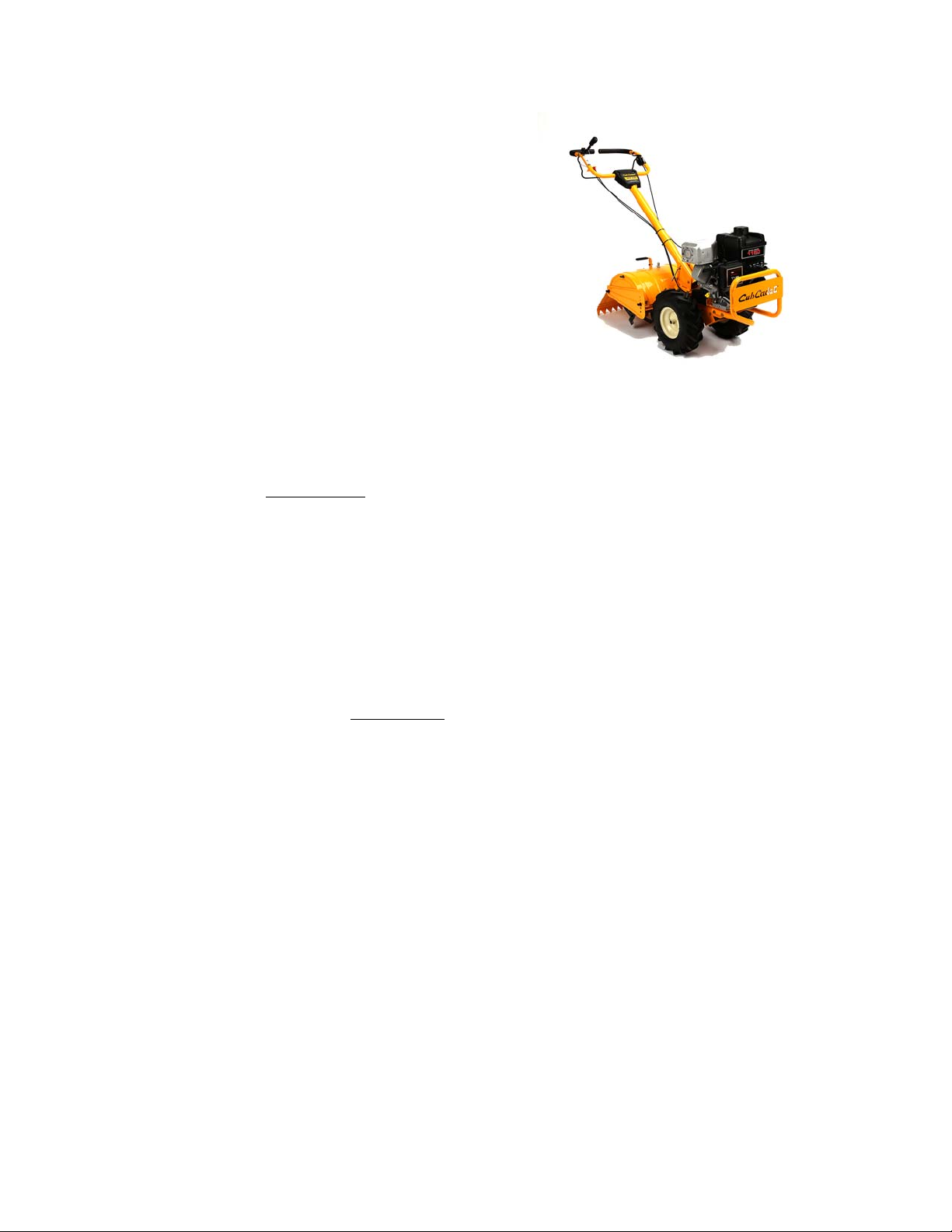
The RT 75 series tiller
The RT 75 tiller is a new tiller line that was introduced
for the 2014 model year . This is a r ear tine, coun ter rot ating
tiller that features:
• Ball bearings on the wheel and tine shafts
• Bronze worm gears.
• A neutral lever to disengage the transmission.
Understanding model and serial numbers
The model number of the RT 75 tiller described in this manual is 21AC482R710.
The break down of what the model number
• 21. . . . . . . . . . . . . . . . . . . . . . . . . . . . . . . . . . . indicates that this is a tiller
means is as follows:
• . . A . . . . . . . . . . . . . . . . . . . . . . . . . . . . . . . . . indicates the sales revision
• . . . . C . . . . . . . . . . . . . . . . . . . . . . . . . . . . . . . indicates the tire size
• . . . . . . 4. . . . . . . . . . . . . . . . . . . . . . . . . . . . . . indicates this is a 400 series tiller
• . . . . . . . 8 . . . . . . . . . . . . . . . . . . . . . . . . . . . . indicates th e a swin g ha ndle (48 0 tra n sm issio n)
• . . . . . . . . . 2R. . . . . . . . . . . . . . . . . . . . . . . . . indicates the engine
• . . . . . . . . . . . . .710 . . . . . . . . . . . . . . . . . . . . . indicates the customer
The serial number is 1J053P10005. The serial number
• 1. . . . . . . . . . . . . . . . . . . . . . . . . . . . . . . . . . . . engineering level
• . J. . . . . . . . . . . . . . . . . . . . . . . . . . . . . . . . . . .month of production (J = October)
• . . .05 . . . . . . . . . . . . . . . . . . . . . . . . . . . . . . . .day of the month
• . . . . . 3. . . . . . . . . . . . . . . . . . . . . . . . . . . . . . .last digit of the year
• . . . . . . .P. . . . . . . . . . . . . . . . . . . . . . . . . . . . .plant it was built in
• . . . . . . . . . 1 . . . . . . . . . . . . . . . . . . . . . . . . . .assembly line number
• . . . . . . . . . . 0005 . . . . . . . . . . . . . . . . . . . . . .number of unit built
Additional technical and service information may also be available to our company authorized service center personnel through our company corporate offices, regional parts distributors and regional service center field support
personnel. Please contact the designated support office in your area or our corporate offices directly should further
service information be needed.
reads as follows:
MTD Products LLC
P.O. Box 368022
Cleveland, OH 44136
Telephone: (800) 800-7310
www.mtdproducts.com
4
Page 9

Maintenance chart
Maintenance item Each use Each 25 hrs. use Each 50 hrs. use
Introduction
Check engine oil
Check air filter
Check transmission oil
Check for loose/broke tines
Check & gap spark plug Replace if worn
Check cooling fins After prolonged storage
Check/clean spark arrestor
Change oil
Note on oil: Change oil after first 5 hrs of use and before prolonged storage
Change air filter
Note on air filter Air filter and pre-filter life vary dramatically with operating conditions
Drain or preserve fuel Before prolonged storage
Fog or lube cylinder Before prolonged storage
*
*
*
*
*
*
*
*
Rotate engine to TDC Before prolonged storage
Remove wheels and lube wheel shaft Once a year
Remove tines and lube tine shaft Once a year
Engine RPM 3500 +
100
5
Page 10

RT 75
6
Page 11
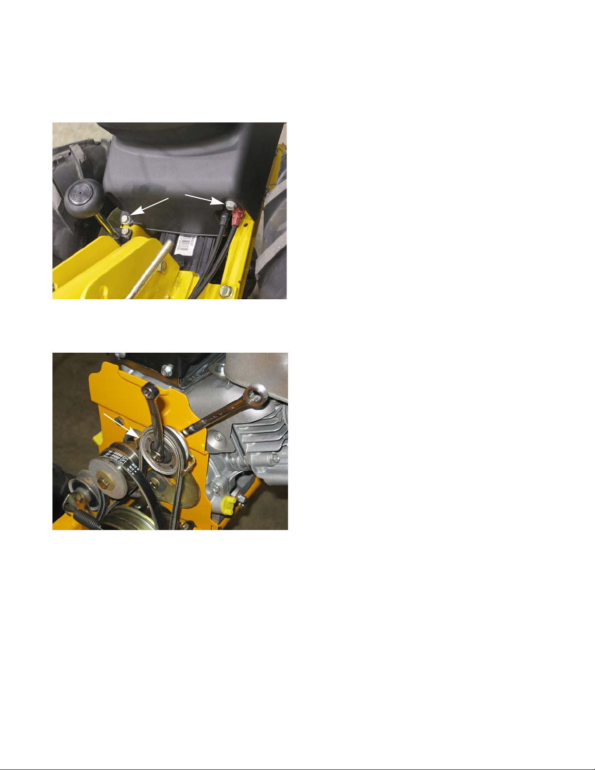
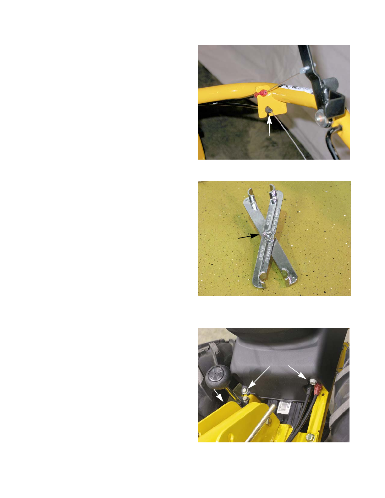
Figure 2.1
screws
Figure 2.2
reverse idler
pulley
CHAPTER 2: BELTS
The RT 75 tiller has two belts; a forward drive belt and a
reverse belt. Both belts have to come off together. MTD
recommends replacing both belts at the same time.
To remove/replace the belts:
1. Disconnect and gr ound the spark plug wire.
2. Remove the two screws that secure the belt cover.
See Figure 2.1.
Belts
3. Swing the belt cover up and off of the tiller.
4. Slide the forward drive belt off of the engine pulley.
5. Loosen the nut and bolt that secure the reverse idler
pulley to the idler bracket using a pair of 7/16”
wrenches.
6. Slide the reverse belt past the belt guards and off of
the idler pulley.
See Figure 2.2.
7
Page 12
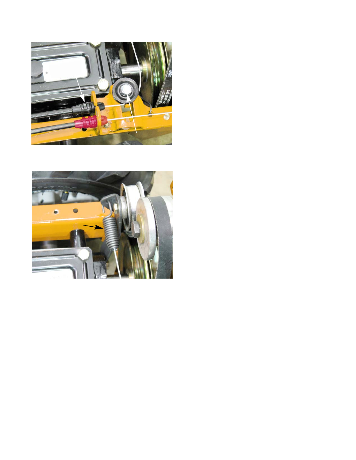
RT 75
Figure 2.3
screws
Figure 2.4
reverse idler spring
belts pushed down
Figure 2.5
fender washer
shoulder
lock washer
spacer
Z-fitting
remove this
screw
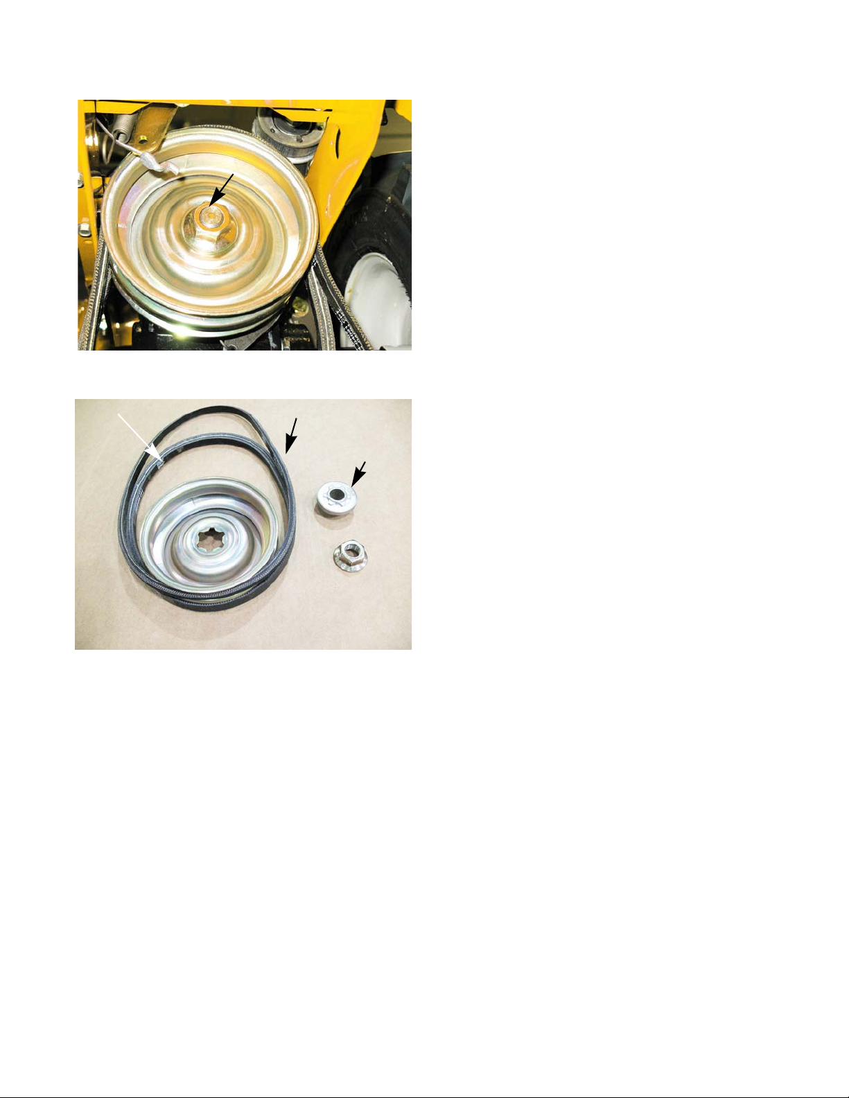
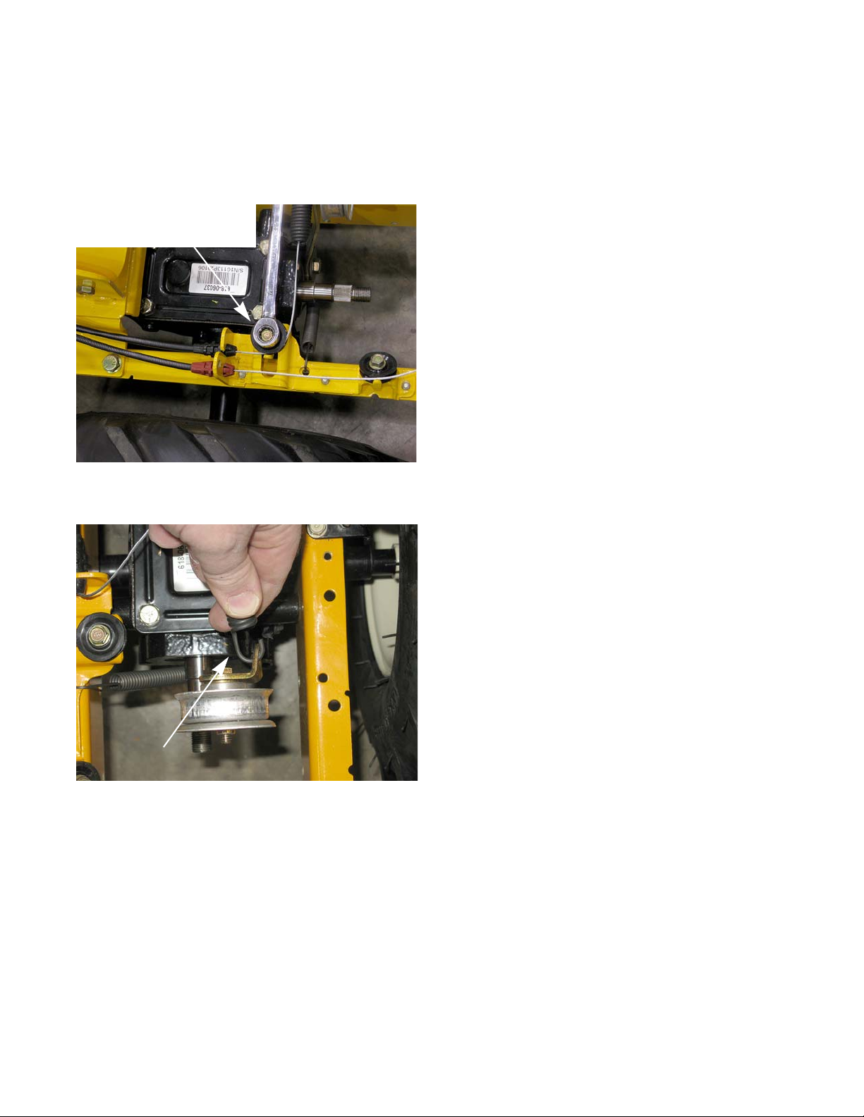
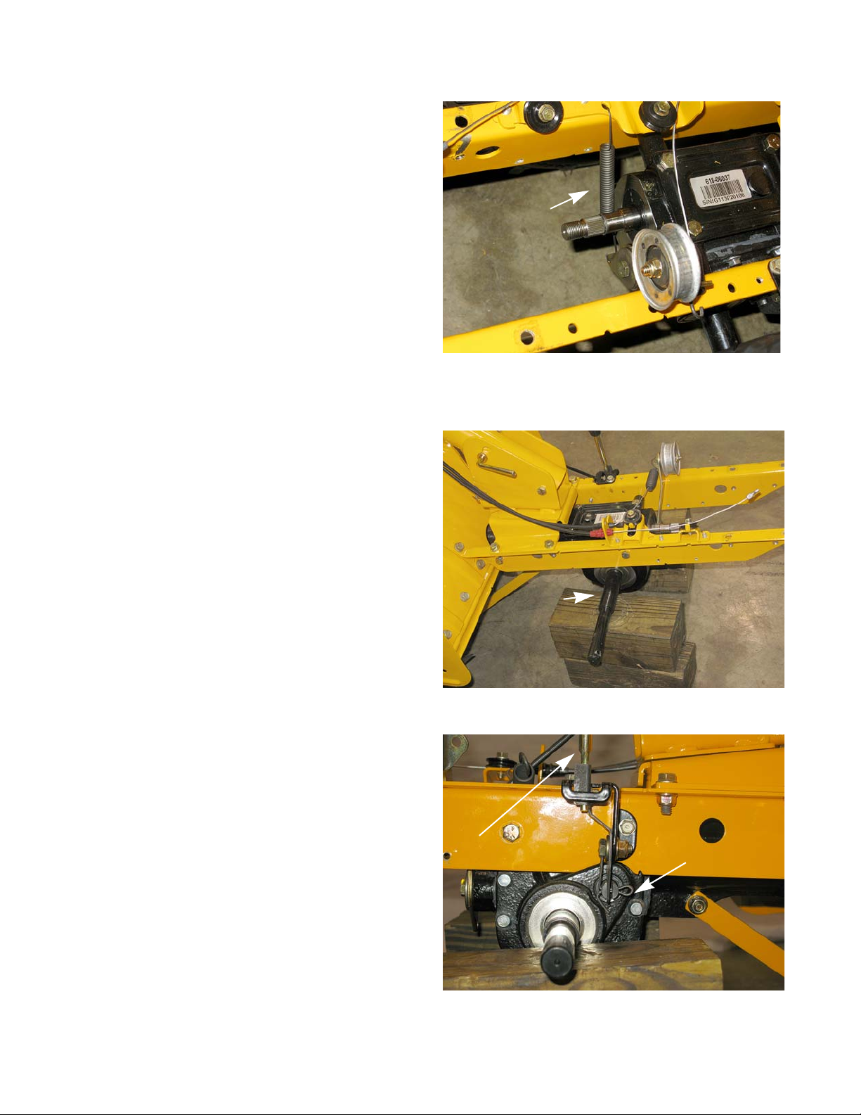
7. Remove the four screws that secure the transmission pulley shield using a 3/8” wrench.
See Figure 2.3.
NOTE: The tire was removed for this picture. It is
not required to remove the tire to remove the
belts.
8. Push both belts down onto the transmission pulley.
See Figure 2.4.
9. Unhook the reverse idler spring. See Figure 2.4.
10. Unhook the rever se cable Z-fitting from the reverse
idler bracket.
11. Remove the reverse idler bracket using a 1/2”
wrench.
See Figure 2.5.
8
Page 13
Belts
Figure 2.6
7/8” nut
Figure 2.7
forward drive belt
reverse belt
hub
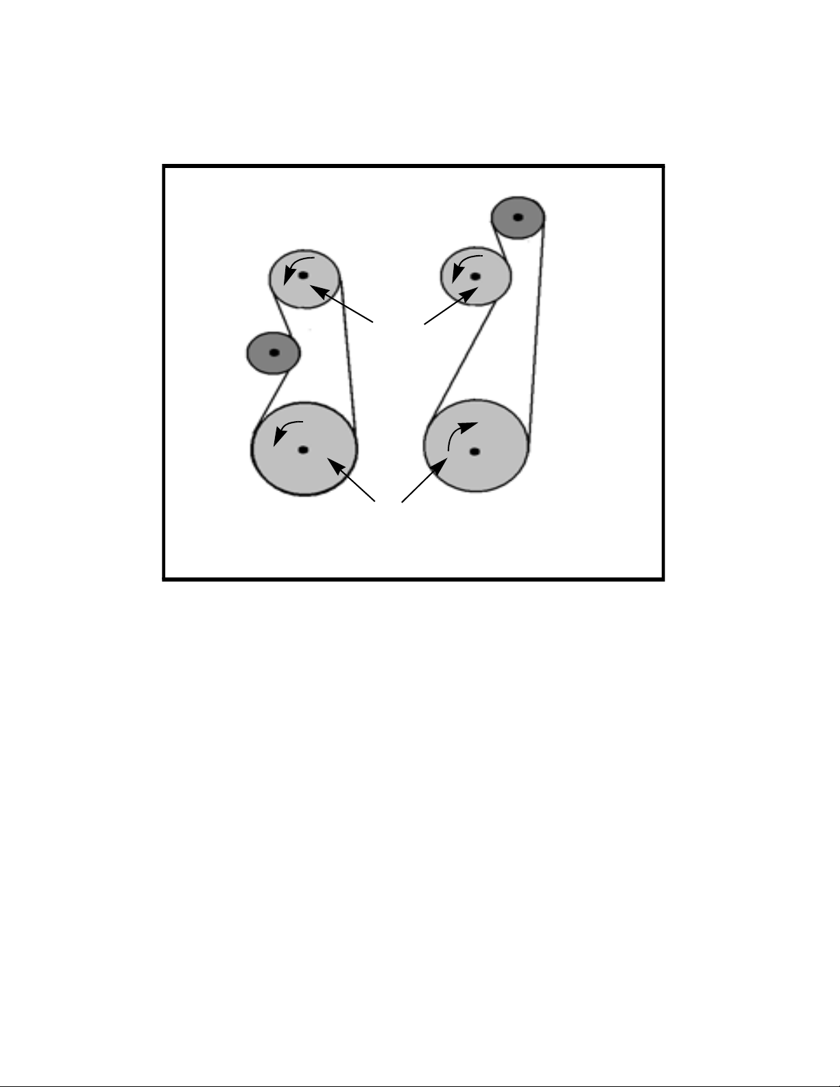
12. Remove the nut that secures the transmission pulley
using a 7/8” socket and an impact wrench.
See Figure 2.6.
13. Slide the transmission pulley and both belts off
together.
14. Position the new belts on the transmission pulley.
See Figure 2.7.
15. Install the belts by following steps 1 through 13 in
reverse order.
NOTE: The transmission pulley has a star shaped center
hole. When installing the pulley, the star must fit
over the raised star on the hub.
16. Test run the tiller in a safe area before returning it to
service.
See Figure 2.7.
9
Page 14
RT 75
Belt Routing
Forward drive belt
Reverse drive belt
Transmission pulley
Engine
Pulley
10
Page 15
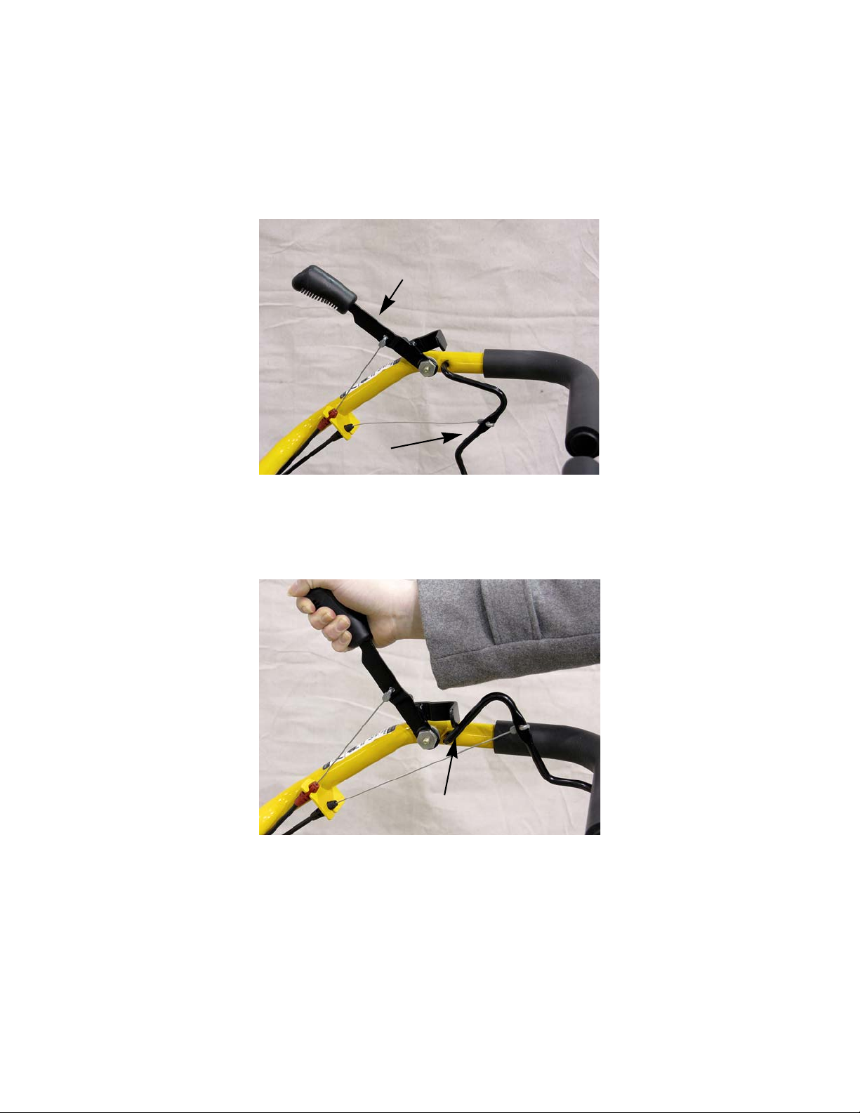
Figure 3.1
reverse lever
forward drive bail
Figure 3.2
Reverse lever hitting
the drive bail
CHAPTER 3: CABLES
The RT 75 tiller has a forward drive cable and a reverse drive cable. The forward drive cable is actuated by a bail
that the operator squeezes. The reverse drive cable is actuated by a lever.
See Figure 3.1.
Cables
The shape of the drive bail and reverse lever will help prevent the operator from engaging the reverse lever while
in the forward mode. As the reverse lever is engaged, the bend on the bottom of it hits the drive bail making it ne ces
sary to release the drive bail. See Figure 3.2.
-
11
Page 16
RT 75
Figure 3.3
Disconnect the
cable fitting
Figure 3.4
Ford fuel
line tool
Figure 3.5
Remove these
screws
washer
Forward drive cable
To remove/replace the forward drive cable:
1. Disconnect and ground the spark plug wire.
2. Disconnect the black cable fitting from the handle bar
bracket.
NOTE: A ford fuel line tool is useful to compress the
See Figure 3.3.
ears on the cable fitting while removing it.
See Figure 3.4.
3. Unhook the Z-fitting from the forward drive bail.
4. Remove the two screws that secure the belt cover.
See Figure 3.5.
5. Swing the belt cover up and off of the tiller.
12
Page 17
Cables
Figure 3.6
Loosen this screw
Disconnect
this cable
Figure 3.7
Disconnect cable
6. Loosen, but do not remove, the screw securing the
cable pulley.
7. Slip the cable off of the pulley.
8. Disconnect the black cable fitting from the cable
bracket.
9. Unhook the spring end of the cable from the forward
idler bracket.
See Figure 3.6.
See Figure 3.6.
See Figure 3.7.
NOTE: The spring end of the cable is to help prevent over
tensioning of the drive belt.
10. Install the cable by following the previous steps in
reverse order.
11. Test run the tiller in a safe area before returning it to
service.
13
Page 18

RT 75
Figure 3.8
Disconnect the
cable fitting
Figure 3.9
Remove these
screws
Figure 3.10
Loosen this screw
Z-fitting
Reverse drive cable
To remove the reverse drive cable:
1. Disconnect and ground the spark plug wire.
2. Disconnect the red cable fitting from the handle bar
bracket.
3. Unhook the Z-fitting from the reverse drive lever.
4. Remove the two screws that secure the belt cover.
See Figure 3.9.
See Figure 3.8.
NOTE: The left screw has a washer to prevent the
slot in the cover from opening up as the screw
is tightened.
5. Swing the belt cover up and off of the tiller.
6. Slide the forward drive belt off of the engine pulley.
7. Slide the reverse belt off of the idler pulley.
7a. Loosen the nut and bolt that secures the idler
pulley to the idler bracket.
7b. Slide the belt past the belt guides.
8. Loosen, but do not remove, the screw securing the
cable pulley.
See Figure 3.10.
14
Page 19

Cables
Figure 3.11
Disconnect
this cable
9. Disconnect the red cable fitting from the cable
bracket.
10. Disconnect the cable Z-fitting.
11. Install the reverse cable by following the previous
steps in reverse order.
12. Test run the tiller in a safe area before returning it to
service.
See Figure 3.11.
15
Page 20

RT 75
16
Page 21
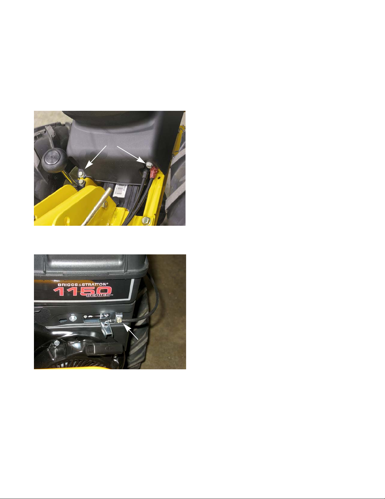
Figure 4.1
Remove these
screws
Figure 4.2
throttle cable clamp
CHAPTER 4: ENGINE
At the time this manual was written, a Briggs and Stratton engine was the only engine option for the RT 75 tiller.
If a different brand of engine is used, the removal/replacement procedures will be essentially the same.
Engine removal
To remove/replace the engine:
1. Disconnect and gr ound the spark plug wire.
2. Remove the two screws that secure the belt cover.
See Figure 4.1.
3. Swing the belt cover up and off of the tiller.
Engine
4. Set the throttle to the full throttle position.
5. Remove the throttle cable clamp using a flat headed
screwdriver.
6. Disconnect the throttle cable from the throttle lever.
See Figure 4.2.
17
Page 22

RT 75
Figure 4.3
reverse idler
pulley
Figure 4.4
Unhook spring
Belts pushed down
Figure 4.5
screws
7. Slide the forward drive belt off of the engine pulley.
8. Loosen the nut and bolt that secures the reverse
idler pulley to the idler bracket, using a pair of 7/16”
wrenches.
9. Slide the reverse belt past the belt guards a nd of f of
the idler pulley.
10. Unhook the reverse idler spring. See Figure 4.4.
See Figure 4.3.
11. Unhook the reverse cable Z-fitting from the reverse
12. Remove the four screws, two on each side, that
13. Remove the four engine mounting screws, using a
14. Lift the engine off of the tiller and place it in a safe
idler bracket.
secure the front bumper to the frame, using a 1/2”
wrench.
1/2” wrench.
work area.
NOTE: If replacing the engine, continue to the next
18
step.
Page 23
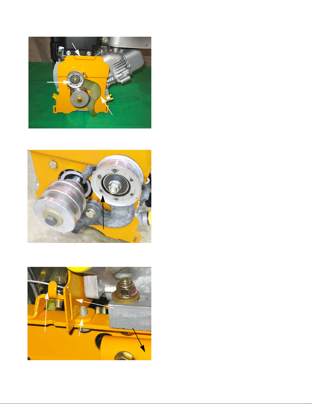
Engine
Figure 4.6
motor cover plate
reverse idler bracket
engine
pulley
Figure 4.7
Spot welds must face away from
the idler bracket
Figure 4.8
cable pulley
screw
bumper
cover
plate
15. Transfer the engine pulley, reverse idler bracket and
the motor cover plate to the new engine.
4.6.
NOTE: If the idler pulley was removed from the idler
bracket, it must be reassembled so that the spot
welds face away from the idler bracket to ensure
proper belt alignment.
See Figure 4.7.
See Figure
Engine Installation
16. Set the engine, with the motor cover plate installed,
on the tiller.
NOTE: The motor cover plate must sit between the cable
pulley bracket and the screw securing the cable
pulley bracket.
17. Tip the engine to the rear of the tiller and slide the
bumper between the engine and the frame.
18. Install the four engine mounting screws, using a 1/2”
wrench.
19. Follow steps 1 through 13 in the previous section in
reverse order.
20. Test run the tiller in a safe area before the tiller is
returned to service.
NOTE: The engine RPM should be set to 3500 RPMs for
proper operation.
See Figure 4.8.
19
Page 24

RT 75
20
Page 25
Transmission removal
Figure 5.1
Loosen screw and slide
cable off of the pulley
Figure 5.2
Unhook the cable
Transmission Removal
CHAPTER 5: TRANSMISSION REMOVAL
1. Remove the belts by following the procedures
described in Chapter 2: Belts.
2. Remove the engine by following the steps described
in Chapter 4: Engine Removal.
3. Loosen the forward drive cable pulley, using a 3/8”
wrench, and slide the cable off of the pulley.
See Figure 5.1.
4. Unhook the cable. See Figur e 5.2.
21
Page 26
RT 75
Figure 5.3
idler bracket
spring
Figure 5.4
Support the
wheel shafts with
wood blocks
Figure 5.5
cotter pin
Neutral lever
5. Unhook the idler bracket spring. See Figure 5.3.
6. Remove the wheels.
7. Support the wheel shafts with wood blocks.
See Figure 5.4.
NOTE: Any time the wheels are removed, or once a
year, the wheel shafts should be coated with antiseize or grease.
8. Remove and discard the cotter pin that holds the
neutral lever to the transmission shifter fork.
See Figure 5.5.
22
Page 27

Transmission Removal
Figure 5.6
Drag bar
Remove nut
and bolt
Figure 5.7
screws
handle mount nuts and bolts
Figure 5.8
Remove these screws
9. Disconnect the front of the drag bar, using a 5/8”
wrench and a 1/2” wrench.
10. Remove the four screws that hold the frame rails to
the transmission, using a 1/2” wrench.
See Figure 5.7.
See Figure 5.6.
11. Loosen, but dot remove, the handle mount nuts and
bolts.
12. Remove the two screws that hold the depth bar
bracket to the rear of the transmission, using a 1/2”
wrench.
See Figure 5.8.
23
Page 28

RT 75
Figure 5.9
Figure 5.10
Bow tie clip
Figure 5.11
Direction of rotation
Front of tiller
Curve of the tine
13. Lift the frame, handle bar and tine shield off as one
unit.
See Figure 5.9.
14. Remove the tines:
14a. Remove the bow tie clip and clevis pin.
See Figure 5.10.
14b. Slide the tines off of the shaft.
NOTE: Any time the tines are removed, or once a
year, the tine shafts should be coated with
anti-seize or grease.
NOTE: When installing the tines, make sure the
curve of the tine is facing the direction of
rotation.
See Figure 5.11.
24
Page 29

Transmission Removal
Figure 5.12
idler bracket
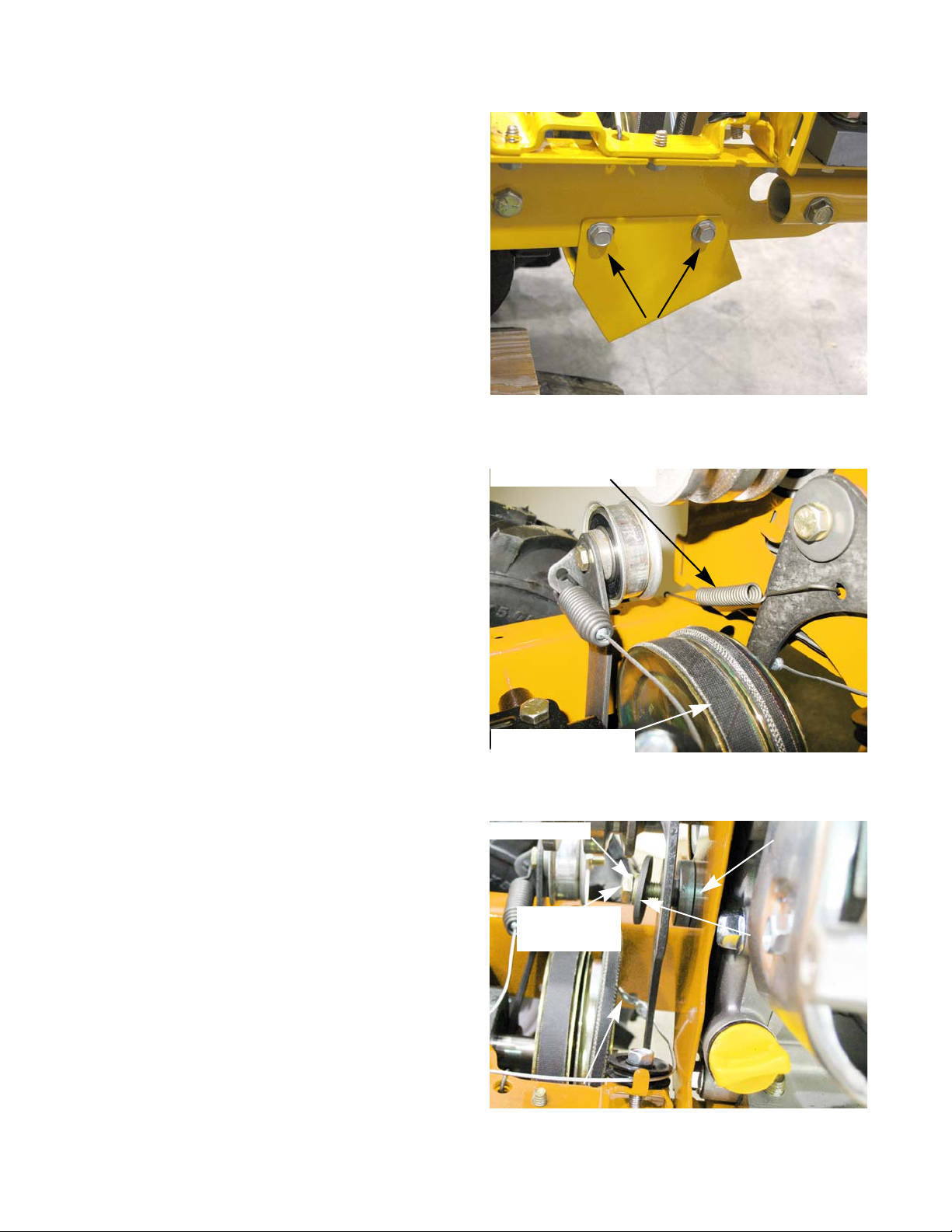
15. Remove the idler bracket, using a 1/2” wrench.
See Figure 5.12.
16. Install the transmission by following the previous
steps in reverse order.
17. Test run the tiller in a safe area before returning it to
service.
25
Page 30

RT 75
26
Page 31

Transmission Overhaul
Figure 6.1
Front
Transmission
Cover
Fill plug
Figure 6.2
Oil Seal
CHAPTER 6: TRANSMISSIO N OVERHAUL
The 460 series transmission is equipped with a neutral feature that will disengage the wheel shaft from the transmission. This allows the tiller to be pushed without the engine driving it. The neutral mechanism is a dog clutch that is
splined to the wheel shaft. When the neutral lever is moved to the engaged position, the dog clutch slides into the
worm gear, allowing the transmission to drive the wheel shaft. When the lever is moved to the neutral position, the
dog clutch slides out of the worm gear, allowing the wheel shaft to rotate freely.
Transmission disassembly
NOTE: The drive shaft and the wheel shaft cannot be removed from the transmission separately.
1. Remove the transmission from the tiller by following the steps described in Chapter 5: Transmission Removal.
2. Drain the transmission.
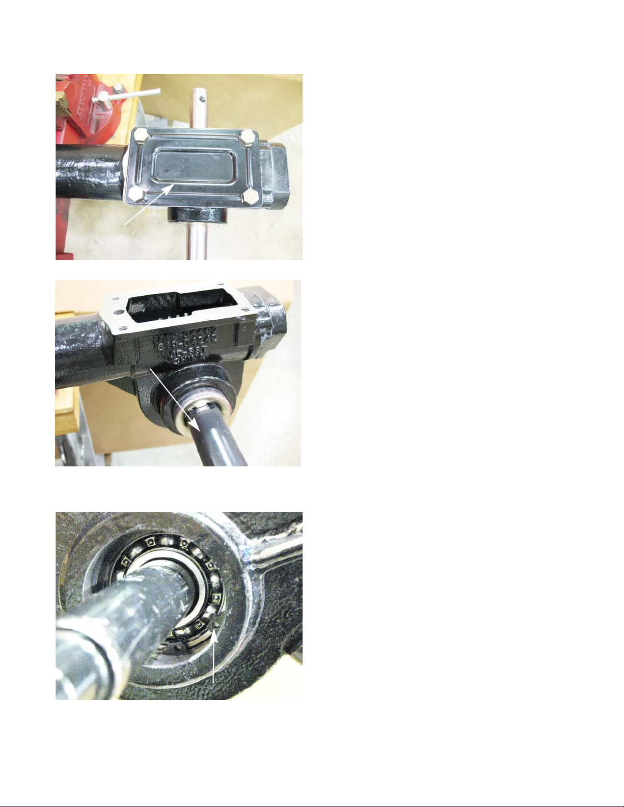
2a. Remove the four hex flange screws securing
the front transmission cover to the transmission
housing using a 1/2” wrench.
2b. Wedge a sharp 5-in-1 painters tool or putty
knife in between the cover and the transmission
housing.
See Figure 6.1.
2c. Pry the cover off.
2d. Turn the transmission over and drain the oil into
a suitable container.
2e. Allow all of the gear oil to drain from the trans-
mission.
NOTE: The front cover has a fill plug.
3. Secure the transmission in a soft jawed vise.
4. Clean the gasket fr om the front transmission housing
and cover, using a scraper.
5. Clean the rust and dirt off of the tine and wheel
shafts.
6. Remove the left and right tine wheel oil seals from
the transmission housing.
NOTE: Use of the Thexton seal removal tool kit #TWX-
4006 is the preferred method of removing the
seals.
For information on purchasing this tool kit contact:
Thexton Toolworx
1157 Valley Park Drive. Suite 150
Shakopee, MN 55379
800-328-6277
• Instructions on how to use this tool kit can be found in manual number 769-02093 available from MTD
Publications.
NOTE: Make certain the transmission oil seal bores are not damaged during removal.
27
Page 32

RT 75
Figure 6.3
Alignment pins
Side cover
Figure 6.4
Figure 6.5
Snap ring
Shift fork oil seal
Wheel shaft bearing
7. Remove the retaining ring that secures the right
wheel shaft bearing, using a pair of snap ring pliers.
8. Remove the eight screws that secure the side cover
to the transmission housing, using a 3/8” wrench.
See Figure 6.3.
NOTE: It is not necessary to remove the snap ring
and the left wheel shaft bearing. They will
come off with the side cover.
9. Gently pry the side cover off of the transmission.
See Figure 6.4.
NOTE: There are two alignment pins that go
through the side cover into the transmission
housing.
10. Push the wheel shaft to th e right, forcing the right
wheel shaft bearing out of the transmission housing.
NOTE: The bearing is a slip fit. It may take several
tries of pushing the wheel shaft to the right,
while wiggling it, to walk the bearing out of
the transmission housing.
11. Remove the bearing and washer from th e r igh t sid e
of the wheel shaft.
12. Remove the snap ring from the side cover.
13. Remove the wheel shaft bearing from the side
cover.
See Figure 6.5.
14. Remove the shift fork oil seal from the side cover.
28
Page 33
Transmission Overhaul
Figure 6.6
Rear transmission cover
Figure 6.7
Thexton seal removal tool
Figure 6.8
Snap ring
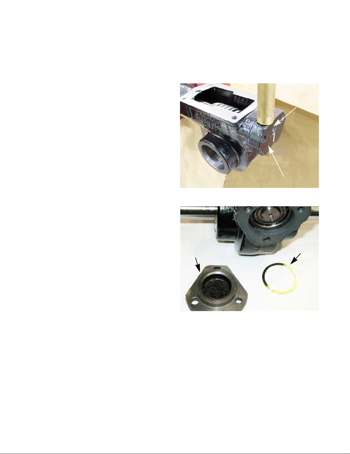
15. Remove the four hex flange screws holding the rear
transmission cover to the transmission housing,
using a 1/2” wrench.
16. Wedge a sharp 5-in-1 painters tool or putty knife in
between the cover and the transmission housing.
17. Pry the cover off.
18. Clean the gasket from the rear transmission housing
and cover.
NOTE: The rear cover does not have a fill plug.
19. Remove the tine shaft oil seals from the transm ission
housing .
See Figure 6.7.
See Figure 6.6.
20. Remove the snap rings that secure the tine shaft
bearings, using a pair of snap ring pliers.
See Figure 6.8.
21. Push the tine shaft to the right, forcing the right tine
shaft bearing out of the transmission housing.
NOTE: The bearing is a slip fit. If it is stuck, use a block of
wood and a large hammer.
NOTE: The washer will be damaged by the Hi-Pro key.
22. Remove the bearing and washer from the right side
of the tine shaft.
23. Slide the tine shaft back into the housing until the HiPro key contacts the tine shaft worm gear.
24. Rotate the tine shaft until the Hi-Pro key slides into
the worm gear keyway.
29
Page 34
RT 75
Figure 6.9
Rear Bearing Cap
Place punch
here
Figure 6.10
Shim
Bearing cap
25. Drive the tine shaft to the left, forcing the left tine shaft bearing out of the transmission housing.
26. If the bearing is stuck, use a block of wood and a large hammer.
NOTE: The washer will be damaged by the Hi-Pro key.
27. Remove the tine shaft.
28. Remove the remaining lower hex flange screw
securing the rear bearing cap, using a 1/2” wrench.
See Figure 6.9.
NOTE: The top two screws were removed with the
depth bar bracket.
29. Using a brass punch and hammer, rotate the rear
bearing cap to break the seal.
30. Once the rear bearing cap is rotated enough to
allow access to one of the corners, use the bras s
punch to drive the cover off.
See Figure 6.9.
31. Clean the sealant fr om the rear of the transmission
32. Remove the rear bearing cap shim(s).
housing and the bearing cap.
See Figure 6.10.
30
Page 35

Transmission Overhaul
Figure 6.11
Figure 6.12
Rear bearing
Front bearing
Figure 6.13
33. Measure the overall thickness of the rear bearing
shims using a dial caliper.
34. Record the measurement for future reference.
35. Inspect the rear tapered roller bearing assembly for
damage or wear.
See Figure 6.11.
36. Thoroughly clean the exposed portion (front) of the
drive shaft.
37. Slowly push the drive shaft assembly rearward and
out of the transmission assembly.
NOTE: The front tapered roller bearing should come out
with the drive shaft. If it did not, remove it from the
transmission housing.
NOTE: Inspect the front tapered roller bearin g for we ar or
damage.
• Inspect the drive shaft.
• Check the operation of the one way clutch.
38. Remove the tine shaft worm gear.
39. Remove the wheel shaft, worm gear, and neutral
assembly from the left side of the transmission.
Figure 6.13.
See
31
Page 36

RT 75
Figure 6.14
Shifter fork
Clutch collar
Spring
Washer
Snap ring
Worm gear
Snap ring
Snap ring
Figure 6.15
Front drive shaft oil seal
40. Slide the shifter fork out of the dog clutch collar.
41. Remove the snap ring that retains the spring and
washer, using a pair of snap ring pliers.
42. Slide the washer, spring, and the dog clutch collar
off of the wheel shaft.
43. Remove the two snap rings that secure the worm
gear to the wheel shaft.
44. Remove the front drive shaft oil seal, using a flat
blade screwdriver.
45. Remove the front inter nal snap ring, using snap ring
pliers.
46. Remove the front tapered roller bearing race by
lightly tapping on the perimeter, using a blunt ended
punch and a hammer or a bearing driver.
47. The race should be ge ntly pushed into the center of
the transmission housing for ease of removal.
48. Clean and inspect all of the parts for signs of wear
or damage.
32
Page 37

Trans mission assembly
Figure 6.16
Dial Caliper
Washers
Figure 6.17
Bearing race
Snap ring
Figure 6.18
Worm gear
Transmission Overhaul
1. Thoroughly clean the entire transmission housing.
2. Clamp the transmission housing in a soft jawed vice.
3. Make certain all the drive shaft components are
accounted for.
4. Locate both hex flang e screws that were securing the
hood bracket to the transmission assembly.
5. Locate two sets of flat washers that would equal
approximately 0.120” in thickness (the thickness of
the hood bracket).
NOTE: Measure the thickness of both washers using a
dial caliper.
See Figure 6.16.
6. Install the front snap r ing using snap ring pliers.
7. Lubricate and install the front tapered roller bearing
race into the front of the transmission housing. It
should seat up against the front retaining ring.
Figure 6.17.
NOTE: The front race is installed from inside the transmis-
sion housing.
8. Install a new front oil seal.
9. Place the tine shaft worm gear in the transmission
housing.
See Figure 6.18.
See
33
Page 38

RT 75
Figure 6.19
Snap ring grooves
Dog clutch side
Worm gear bearing surface
Figure 6.20
Dog clutch
Figure 6.21
Dogs
Dog clutch collar
10. Assemble the wh eel sh af t and the neutr al assembly.
10a. In the middle of the wheel shaft there is a sec-
tion that is splined. On one side of the splines
there are two snap ring grooves. On that side,
install a snap ring in the grove closest to the
splines.
10b. Slide the worm gear onto the wheel shaft so
that it rests against the snap ring, on the side
opposite of the splines.
See Figure 6.19.
NOTE: The dog clutch side of the worm gear must
face the splines when it is installed.
See Figure 6.20.
10c. Install a snap ring in the groove next to the
worm gear.
10d. Slide the dog clutch collar onto the spline side
of the wheel shaft, with the dogs facing the
worm gear.
See Figure 6.21.
34
Page 39

Transmission Overhaul
Figure 6.22
Spring
Washer
Clutch collar
Snap ring
Figure 6.23
Shifter fork
Figure 6.24
shifter fork oil seal
10e. Slide the spring onto the wheel shaft so that it
is next to the clutch collar.
10f. Slide the washer onto the wheel shaft so that it
is against the spring.
10g. Install the third snap ring while compressing the
spring and washer.
1 1. Slide the shift fork into the groove in the clutch collar .
See Figure 6.23.
See Figure 6.22.
12. Slide the wheel shaft assembly into the transmission
housing.
NOTE: Do not install the wheel shaft bearings at this time.
13. Install the tapered roller bearings onto both ends of
the drive shaft.
14. Slide the drive shaft into the transmission housing
from the rear opening.
15. Apply a 3/16” (4.75mm) bead of Threebond® 1 217H,
Permatex
on the side cover..
16. Install the side cover. Tighten the screws to a torque
of 110 - 125 in lbs (12 - 14 Nm).
17. Install the left side wheel shaft bearing.
® Ultra Black #82180 or equivalent sealant
18. Install the snap ring that retains the lef t wheel bearing
using a pair of snap ring pliers.
19. Install the right wheel shaft bearing.
20. Install the snap ring that retains the right wheel bearing using a pair of snap ring pliers.
21. Install a new shift fork oil seal. See Figure 6.24.
35
Page 40

RT 75
Figure 6.25
Snap ring
Figure 6.26
bearing race
22. Install the tine shaft. It will pass through the bearing
bore, through the tine shaft worm gear and out the
other side of the transmission.
23. Slide the Hi-Pro key into the tine shaft worm gear.
24. On each side, slide the washer over the tine shaft.
25. Insert the tine shaft bearings over the tine shaft until
they pass the snap ring grooves in the transmission
housing.
NOTE: A bearing installation tool can be made
using a 1” I.D. PVC pipe by 7” long.
26. Install both of the snap rings that retain the tine
shaft bearing in the transmission housing using a
pair of snap ring pliers.
27. Slide th e drive sha ft assembly into the front tapered
roller bearing race.
See Figure 6.25.
28. Position the re ar bea rin g race over th e r ear tapered
roller bearing.
29. Set the rear bearing cap in position.
NOTE: Do not put sealant on the bearing cap.
30. Fasten the rear bearing cap to the transmission
housing with the hex flange screws, using a 1/2”
wrench.
NOTE: The washers from step five go on the top
31. Tighten the hex screws to a torque of 100 in lbs. (1 1
Nm).
NOTE: The drive shaft rides in a pair of tape re d ro ller bea rin gs. Tapered roller bearings have low fr ictio n, a lot
See Figure 6.26.
two screws.
of surface area and they bear thrust loads very well. The worm drive system used in this tiller is very
sturdy, but it generates high thrust loads on the drive shaft. If the end-play is too tight, the bearings will
overheat as they are jammed into their races. When the end play is too loose, the bearings will move
around in their races. This will cause damage to the rollers, the cages, and will put dimples in the
races.
36
Page 41

Transmission Overhaul
Figure 6.27
Drive Shaft
Dial Indicator
Magnetic Base
Figure 6.28
Wheel shaft
Tine shaft
32. Shim the rear drive shaft bearing to set the drive
shaft end play to 0.005” - 0.015” (0.13 -. 038 mm).
32a. Set up a dial indicator at the front of the drive
shaft.
See Figure 6.27.
32b. Rotate the tine shaft towards the rear of the
transmission to seat the drive shaft into the rear
bearing cap.
NOTE: A screwdrivers or punch can be inserted into the
shaft for leverage to rotate it.
32c. Zero the dial indicator when the drive shaft is
seated.
32d. Rotate the tine shaft towards the front of the
transmission.
32e. Read the dial indicator.
NOTE: This is the end play.
32f. Subtract 0.010” (0.38 mm) from the total shaft
end play measurement. This is the thickness of
the stack of shims that should be used between
the rear bearing cap and the bearing race.
32g. Remove the rear bearing cap and install the stack of shims described in step 32f.
32h. Fasten the rear bearing cap to the tr ansmission housing with the hex flange screws, using a 1/2” wrench.
32i. Tighten the hex screws to a torque of 100 in lbs (11 Nm).
32j. Repeat step 32a. through step 32e. The end play should be 0.000 to 0.010 at this point.
NOTE: The drive shaft needs to be over shimmed by 0.005” (0.13 mm) to make up for the sealant that will be
added to the bearing end cap.
See Figure 6.28.
33. Apply a 3/16” (4.75mm) bead of Threebond® 1217H, Permatex® Ultra Black #82180 or equivalent sealant
on the rear bearing cap.
37
Page 42

RT 75
34. Secure the rear bearing cap to the transmission assembly with the hex flange screws with the washers used
earlier, using a 1/2” wrench.
NOTE: Tighten the hex screws to a torque of 100 in lbs (11 Nm).
NOTE: Leave the two top screws in place until the sealant has cured. Then they should be removed.
35. Verify the end pla y is bet we e n 0.005” - 0.015” by repeating step 32a. through step 32e.
36. Install both of the wheel shaft seals.
37. Install both of the tine shaft seals.
38. Fill the transmission with 30 oz (0.9 L) of 85W-140 gear lube.
39. Install the transmission covers using new gaskets.
40. Install the transmission in the tiller.
41. Test run the tiller in a safe area before returning it to service.
38
Page 43

Tines
Figure 7.1
Euro tines
Figure 7.2
New
Worn
Sharp point
CHAPTER 7: TINES
The RT 75 tiller is a counter rotating tiller equipped with
Euro tines. If the tines are properly installed, the tines will
cut into the ground and break up the soil. If the tines are
installed backwards, the tines will “hammer” the ground,
making the machine hard to control and will not till the soil.
See Figure 7.1.
Tines
As the tines dig through the ground, the grin ding action
of the soil will put a sharp edge on the tines. Once the tine
has been ground to a sharp point, it must be replaced.
See Figure 7.2.
39
Page 44

RT 75
Figure 7.3
Figure 7.4
bow tie clip
Clevis pin
Figure 7.5
1/2” wrenches
1. Remove the tine hood end cover and the side
shield.
See Figure 7.3.
2. Remove the tine assemblies by removing the clevis
pin and bow tie clip that secures the tine assemblies
to the tine shaft on the transmission.
See Figure 7.4.
NOTE: Replace the nut and bolt if they show signs
of wear or damage.
3. Slide the assemblies off of the tine shaft.
NOTE: If the hub assemblies are frozen to the tine
shaft, a hub puller can be used to remove
them.
4. Remove the old tines from the tine assembly. with a
pair of 1/2” wrenches.
See Figure 7.5.
40
Page 45

Tines
Left Hand Tine
Right Hand Tine
Hold with the sharp edge facing you
Figure 7.6
Left Hand Tine
Right Hand Tine
Hold with the sharp edge facing you
Left Hand Tine
Right Hand Tine
Hold with the sharp edge facing you
Figure 7.7
clevis pin hole
,EFTHANDTINEASSEMBLY
Figure 7.8
Shoulder
end
NOTE: When installing the tines, it is important that the
correct tines are used and they are installed in the
proper orientation.
5. To determine which tine is right or left:
5a. Hold the tines with the cutting edge towards
you.
See Figure 7.6.
5b. If the tine curves to the left, it is a left handed
tine.
5c. If the tine curves to the right, it is a right handed
tine.
NOTE: The right and left tine holders are the same part
number.
NOTE: The end of the tine holder with the clevis pin hole
slides onto the tine shaft first.
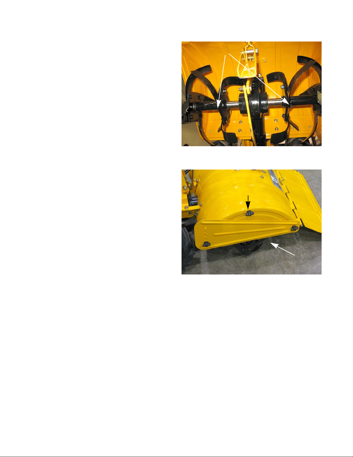
6. Install two left hand tines and two right hand tines to
the flange closest to the shoulder end.
See Figure 7.8.
7. Install four right hand tines on the outside flange of
the left hand tine assembly.
8. Install fou r left ha nd tines on the out side flange of the
right hand tine assembly.
See Figure 7.7.
NOTE: The inside of the curve of the tine should face the
center of the flange.
NOTE: Tighten the nuts and bolts to a torque of 35 ft lbs
(47 Nm)
41
Page 46
RT 75
Figure 7.9
clevis pin
Figure 7.10
Side shield
center wing nut
9. Apply anti-seize to the tine shaft.
10. Installing the assembly.
11. When correctly installed:
• The end of the tine holder with the clevis pin
hole should face towards the transmission.
• The outside tines should curve inward
• The tines should be bolted to the outboard side
of the plate on the tine holder. See Figure 7.9.
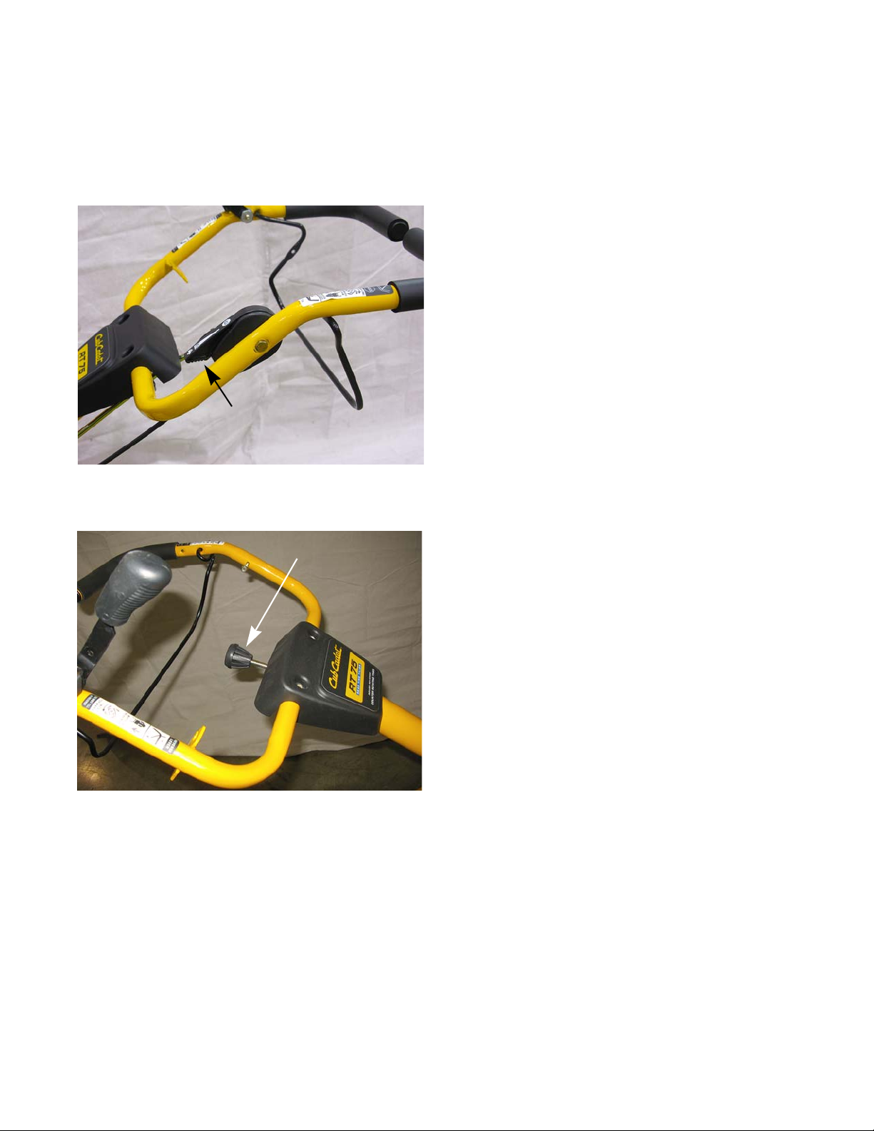
12. Insert the tine hood end panel. Secure it with the
center wing nut.
13. Install the side shield. Secure it with the remaining
wing nuts.
14. Test the tiller in a safe area before returning it to
service.
42
Page 47
Handle bar
Figure 8.1
throttle lever
Figure 8.2
swivel rod knob
CHAPTER 8: SWIVEL HANDLE
To remove/replace the handle bar:
1. Disconnect the forward and reverse cables from the
handle bar , by following the procedures described in
Chapter 3: Cables.
2. Remove the nut and bolt that secures the throttle
lever to the handle bar, using a pair of 7/16”
wrenches.
See Figure 8.1.
Swivel Handle
3. Unthread the swivel ro d knob. See Figure 8.2.
43
Page 48

RT 75
Figure 8.3
cable ties
Figure 8.4
inner cotter pin
outer cotter pin
washer
Figure 8.5
handle adjustment crank
handle mounting bolt
4. Remove and discard both of the cable ties from the
handle bar.
See Figure 8.3.
5. Remove and discard the outer cotter pin that
secures the swivel rod to the swivel latch.
ure 8.4.
NOTE: Do not remove the inner cotter pin.
6. Remove the swivel rod and washer.
7. Remove the handle adjustment crank. See Figure
8.5.
See Fig-
44
Page 49

Swivel Handle
Figure 8.6
nut retension bracket
NOTE: There is a nut retension bracket on the left side of
the handle bar swivel mount. When the handle
mounting nut and bolt is removed, the bracket and
the upper nut will fall off.
8. Remove the handle mounting nut and bolt.
9. Remove the handle bar from the machine.
10. If replacing the handle bar:
10a. Remove the forward drive bail.
10b. Remove the reverse lever.
10c. Remove the front cover and swivel rod bracket.
11. Install the handle bar by following the previous steps
in reverse order.
12. Test run the unit in a safe area before returning it to
service.
See Figure 8.6.
45
Page 50
RT 75
Figure 8.7
upper jam lock nut
Figure 8.8
flat washer
Figure 8.9
lower nut
Swivel Bracket
To rebuild the swivel assembly:
1. Remove the handle bar assembly, by following the
procedures described in the previous section of this
chapter.
NOTE: It is advisable to rebuild the swivel assembly
on the machine. Having the lower bracket
mounted to the frame provides stability while
torquing the lower nut.
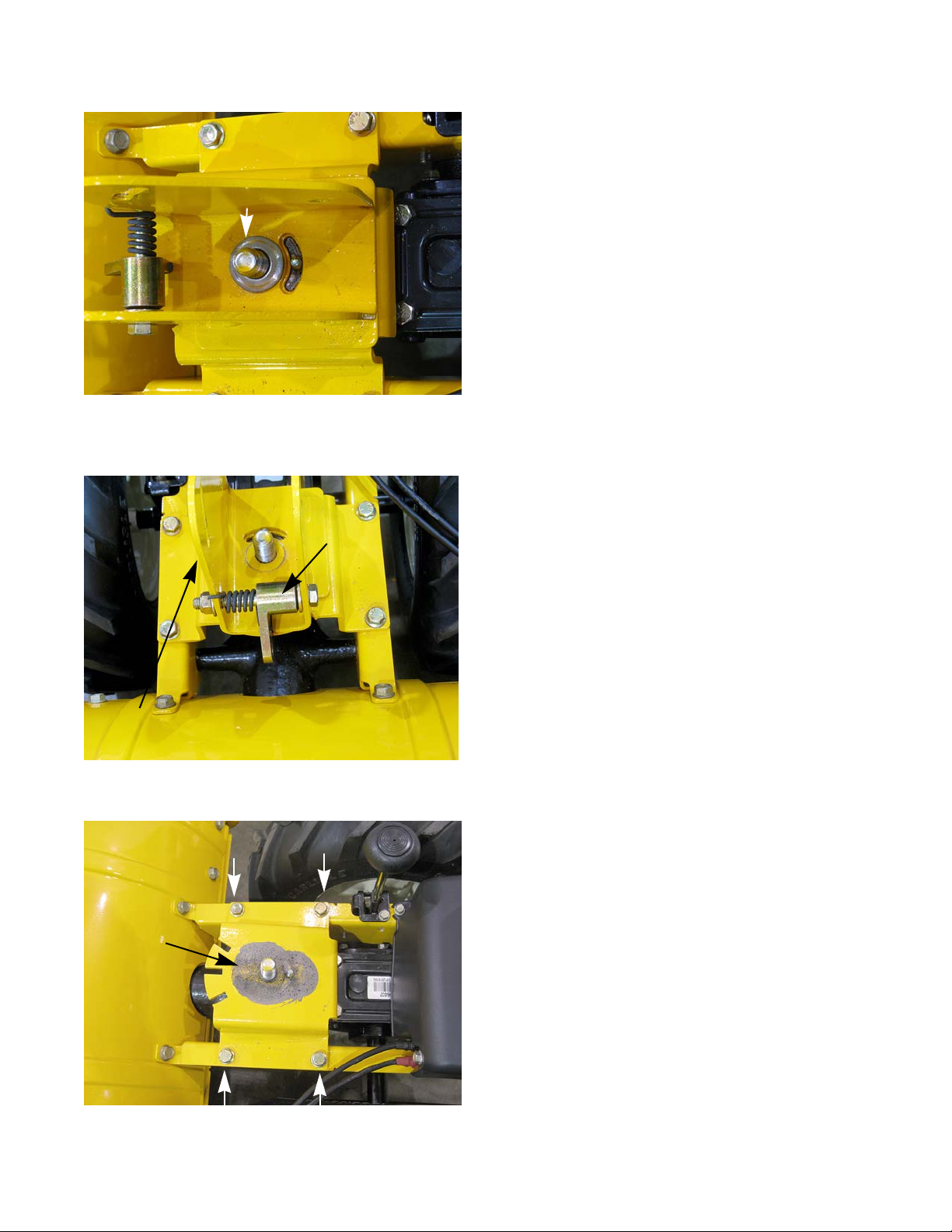
2. Remove the upper jam lock nut from the swivel
assembly, using a 15/16” wrench.
3. Remove the flat washer. See Figure 8.8.
See Figure 8.7.
4. Remove the lower nut, using a 15/16” wrench. See
Figure 8.9.
46
Page 51
Swivel Handle
Figure 8.10
Belleville washer
Figure 8.11
swivel latch
upper swivel bracket
Figure 8.12
anti-seize
5. Remove the Belleville washer. See Figure 8.10.
6. Remove the nut and bolt that the swivel latch and
spring pivot on, using a pair of 9/16” wrenches.
Figure 8.11.
See
7. Remove the swivel latch and spring.
8. Lift the upper swivel latch bracket off of the machine.
9. If the lower bracke t is dama ged or worn, r emove and
replace it by removing the four nuts and bolts that
hold it down, using a pair of 1/2” wrenches.
ure 8.12.
To reassemble the swivel bracket assembly:
10. If removed, install the lower bracket assembly.
11. Apply a generous coating of anti-seize compound to
the lower bracket assembly where the upper and
lower brackets make contact.
See Fig-
47
Page 52

RT 75
Figure 8.13
Torque to
240 - 270 in lbs
Belleville
washer
locking jam nut
12. Install the upper swivel bracket.
13. Install the swivel latch and spring.
14. Install the Belleville washer.
15. Inst all the lo wer nu t an d tig hten it to a torque of 240
- 270 in lbs (27 - 31 Nm).
16. Inst all the flat washer.
17. Install the upper locking jam nut.
18. Install the handle bar by following the procedures
described in the previous section of this chapter.
19. Test run the unit in a safe area before returning it to
service.
See Figure 8.13.
48
Page 53

Page 54

MTD Products Inc - Product Training and Education Department
FORM NUMBER - 769-09590-00
12/2013
 Loading...