

Page 1
Safe Operation Practices • Set-Up • Operation • Maintenance • Service • Troubleshooting • Warranty
OperatOr’s Manual
Rear Tine Tiller — Model RT 65
WARNING
READ AND FOLLOW ALL SAFETY RULES AND INSTRUCTIONS IN THIS MANUAL
BEFORE ATTEMPTING TO OPERATE THIS MACHINE.
FAILURE TO COMPLY WITH THESE INSTRUCTIONS MAY RESULT IN PERSONAL INJURY.
CUB CADET LLC, P.O. BOX 361131 CLEVELAND, OHIO 44136-0019
Printed In USA
Form No. 769-03598
(October 30, 2007)
Page 2

To The Owner
Thank You
Thank you for purchasing a Garden Tiller manufactured by Cub
Cadet LLC. It was carefully engineered to provide excellent
performance when properly operated and maintained.
Please read this entire manual prior to operating the equipment.
It instructs you how to safely and easily set up, operate and
maintain your machine. Please be sure that you, and any other
persons who will operate the machine, carefully follow the
recommended safety practices at all times. Failure to do so could
result in personal injury or property damage.
All information in this manual is relative to the most recent
product information available at the time of printing. Review
this manual frequently to familiarize yourself with the machine,
its features and operation. Please be aware that this Operator’s
Manual may cover a range of product specifications for various
models. Characteristics and features discussed and/or illustrated
in this manual may not be applicable to all models. Cub Cadet
LLC reserves the right to change product specifications, designs
and equipment without notice and without incurring obligation.
Table of Contents
Safe Operation Practices ........................................ 3
Assembly & Set-Up .................................................. 6
Controls & Features ................................................10
Operation ................................................................11
1
This product has met the rigid safety standards of the Outdoor
Power Equipment Institute and an independent testing
laboratory. If you have any problems or questions concerning
the machine, phone your local Cub Cadet dealer or contact us
directly. Cub Cadet’s Customer Support telephone numbers,
website address and mailing address can be found on this page.
We want to ensure your complete satisfaction at all times.
Throughout this manual, all references to right and left side of the
machine are observed from the operating position.
Maintenance & Adjustments .................................13
Service .....................................................................15
Troubleshooting .....................................................16
Warranty ..................................................Back Cover
Record Product Information
Before setting up and operating your new equipment, please
locate the model plate on the equipment and record the
information in the provided area to the right. You can locate the
model plate by standing at the operator’s position and looking
down at the rear of the deck. This information will be necessary,
should you seek technical support via our web site or with your
local Cub Cadet dealer.
MOdel nuMber
serial nuMber
Customer Support
If you have difficulty assembling this product or have any questions regarding the controls, operation, or maintenance of
this machine, you can seek help from the experts. Choose from the options below:
Visit us on the web at www.cubcadet.com
◊
Locate your nearest Cub Cadet Dealer at (877) 282-8684
◊
Write us at Cub Cadet LLC • P.O. Box 361131 • Cleveland, OH • 44136-0019
◊
2
Page 3
Important Safe Operation Practices
WARNING! This symbol points out important safety instructions which, if not followed,
could endanger the personal safety and/or property of yourself and others. Read and follow
all instructions in this manual before attempting to operate this machine. Failure to comply
with these instructions may result in personal injury.
When you see this symbol. HEED ITS WARNING!
CALIFORNIA PROPOSITION 65
WARNING! Engine Exhaust, some of its constituents, and certain vehicle components
contain or emit chemicals known to State of California to cause cancer and birth defects
or other reproductive harm.
WARNING! Battery posts, terminals, and related accessories contain lead and lead
compounds, chemicals known to the State of California to cause cancer and reproductive
harm. Wash hands after handling
DANGER! This machine was built to be operated according to the safe operation practices in
this manual. As with any type of power equipment, carelessness or error on the part of the
operator can result in serious injury. This machine is capable of amputating fingers, hands,
toes and feet. Failure to observe the following safety instructions could result in serious
injury or death.
2
Training
Read, understand, and follow all instructions on the
1.
machine and in the manual(s) before attempting to
assemble and operate. Keep this manual in a safe place for
future and regular reference and for ordering replacement
parts.
Be familiar with all controls and their proper operation.
2.
Know how to stop the machine and disengage them
quickly.
Never allow children under 14 years of age to operate this
3.
machine. Children 14 and over should read and understand
the instructions and safe operation practices in this manual
and on the machine and be trained and supervised by an
adult.
Never allow adults to operate this machine without proper
4.
instruction.
Keep the area of operation clear of all persons, particularly
5.
small children and pets. Stop machine if anyone enters the
area.
Preparation
Thoroughly inspect the area where the equipment is to
1.
be used. Remove all stones, sticks, wire, and other foreign
objects which could be tripped over and cause personal
injury.
Wear sturdy, rough-soled work shoes and close fitting
2.
slacks and shirt. Loose fitting clothes or jewelry can be
caught in moving parts. Never operate this machine in bare
feet or sandals.
Disengage clutch levers and shift (if provided) into neutral
3.
(“N”) before starting the engine.
Never leave this machine unattended with the engine
4.
running.
Never attempt to make any adjustments while engine is
5.
running, except where specifically recommended in the
operator’s manual.
Safe Handling of Gasoline:
To avoid personal injury or property damage use extreme care
in handling gasoline. Gasoline is extremely flammable and the
vapors are explosive. Serious personal injury can occur when
gasoline is spilled on yourself or your clothes which can ignite.
Wash your skin and change clothes immediately.
Use only an approved gasoline container.
a.
Never fill containers inside a vehicle or on a truck
b.
or trailer bed with a plastic liner. Always place
containers on the ground away from your vehicle
before filling.
3
Page 4

When practical, remove gas-powered equipment
c.
from the truck or trailer and refuel it on the ground.
If this is not possible, then refuel such equipment on
a trailer with a portable container, rather than from a
gasoline dispenser nozzle.
Keep the nozzle in contact with the rim of the fuel
d.
tank or container opening at all times until fueling is
complete. Do not use a nozzle lock-open device.
Extinguish all cigarettes, cigars, pipes and other
e.
sources of ignition.
Never fuel machine indoors.
f.
Never remove gas cap or add fuel while the engine
g.
is hot or running. Allow engine to cool at least two
minutes before refueling.
Never over fill fuel tank. Fill tank to no more than ½
h.
inch below bottom of filler neck to allow space for
fuel expansion.
Replace gasoline cap and tighten securely.
i.
If gasoline is spilled, wipe it off the engine and
j.
equipment. Move unit to another area. Wait 5
minutes before starting the engine.
To reduce fire hazards, keep machine free of grass,
k.
leaves, or other debris build-up. Clean up oil or fuel
spillage and remove any fuel soaked debris.
Never store the machine or fuel container inside
l.
where there is an open flame, spark or pilot light
as on a water heater, space heater, furnace, clothes
dryer or other gas appliances.
Operation
Do not put hands or feet near rotating parts. Contact with
1.
the rotating parts can amputate hands and feet.
Do not operate machine while under the influence of
2.
alcohol or drugs.
Never operate this machine without good visibility or light.
3.
Always be sure of your footing and keep a firm hold on the
handles.
Keep bystanders away from the machine while it is in
4.
operation. Stop the machine if anyone enters the area.
Be careful when tilling in hard ground. The tines may catch
5.
in the ground and propel the tiller forward. If this occurs,
let go of the handle bars and do not restrain the machine.
Exercise extreme caution when operating on or crossing
6.
gravel surfaces. Stay alert for hidden hazards or traffic. Do
not carry passengers.
Never operate the machine at high transport speeds on
7.
hard or slippery surfaces.
Exercise caution to avoid slipping or falling.
8.
Look down and behind and use care when in reverse or
9.
pulling machine towards you.
Start the engine according to the instructions found in this
10.
manual and keep feet well away from the tines at all times.
After striking a foreign object, stop the engine, disconnect
11.
the spark plug wire and ground against the engine.
Thoroughly inspect the machine for any damage. Repair
the damage before starting and operating.
Disengage all clutch levers (if fitted) and stop engine
12.
before you leave the operating position (behind the
handles). Wait until the tines come to a complete stop
before unclogging the tines, making any adjustments, or
inspections.
Never run an engine indoors or in a poorly ventilated area.
13.
Engine exhaust contains carbon monoxide, an odorless
and deadly gas.
Muffler and engine become hot and can cause a burn. Do
14.
not touch.
Use caution when tilling near fences, buildings and
15.
underground utilities. Rotating tines can cause property
damage or personal injury.
Do not overload machine capacity by attempting to till soil
16.
too deep at too fast of a rate.
If the machine should start making an unusual noise or
17.
vibration, stop the engine, disconnect the spark plug wire
and ground it against the engine. Inspect thoroughly for
damage. Repair any damage before starting and operating.
Keep all shields, guards, and safety devices in place and
18.
operating properly.
Never pick up or carry machine while the engine is running.
19.
Use only attachments and accessories approved by the
20.
manufacturer. Failure to do so can result in personal injury.
If situations occur which are not covered in this manual, use
21.
care and good judgement. Contact Customer Support for
assistance and the name of you nearest servicing dealer..
Maintenance & Storage
Keep machine, attachments and accessories in safe
1.
working order.
Allow a machine to cool at least five minutes before
2.
storing. Never tamper with safety devices. Check their
proper operation regularly.
Check bolts and screws for proper tightness at frequent
3.
intervals to keep the machine in safe working condition.
Also, visually inspect machine for any damage.
Before cleaning, repairing, or inspecting, stop the engine
4.
and make certain the tines and all moving parts have
stopped. Disconnect the spark plug wire and ground it
against the engine to prevent unintended starting.
Do not change the engine governor settings or over-speed
5.
the engine. The governor controls the maximum safe
operating speed of engine.
Maintain or replace safety and instruction labels, as
6.
necessary.
Follow this manual for safe loading, unloading,
7.
transporting, and storage of this machine.
Always refer to the operator’s manual for important details
8.
if the machine is to be stored for an extended period.
4 sectiOn 2 — iMpOrtant safe OperatiOn practices
Page 5

9.
If the fuel tank has to be drained, do this outdoors.
10.
Observe proper disposal laws and regulations for gas, oil,
etc. to protect the environment.
Notice Regarding Emissions
Engines which are certified to comply with California and federal
EPA emission regulations for SORE (Small Off Road Equipment)
are certified to operate on regular unleaded gasoline, and
may include the following emission control systems: Engine
Modification (EM) and Three Way Catalyst (TWC) if so equipped.
Spark Arrestor
WARNING! This machine is equipped with an
internal combustion engine and should not be used
on or near any unimproved forest-covered,
brushcovered or grass-covered land unless the
engine’s exhaust system is equipped with a spark
arrester meeting applicable local or state laws (if
any).
If a spark arrester is used, it should be maintained in effective
working order by the operator. In the State of California the
above is required by law (Section 4442 of the California Public
Resources Code). Other states may have similar laws. Federal laws
apply on federal lands.
A spark arrester for the muffler is available through your
nearest engine authorized service dealer or contact the service
department, P.O. Box 361131 Cleveland, Ohio 44136-0019.
Average Useful Life
According to the Consumer Products Safety Commission
(CPSC) and the U.S. Environmental Protection Agency (EPA),
this product has an Average Useful Life of seven (7) years, or 130
hours of operation. At the end of the Average Useful Life, buy
a new machine or have the machine inspected annually by an
authorized service dealer to ensure that all mechanical and
safety systems are working properly and not worn excessively.
Failure to do so can result in accidents, injuries or death.
WARNING! Your Responsibility—Restrict the use of this power machine to persons who read, understand and
follow the warnings and instructions in this manual and on the machine.
SAVE THESE INSTRUCTIONS!
5sectiOn 2 — iMpOrtant safe OperatiOn practices
Page 6
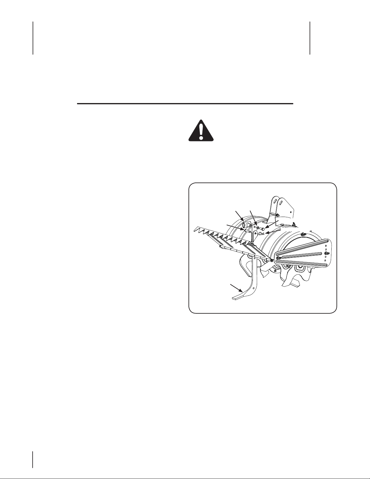
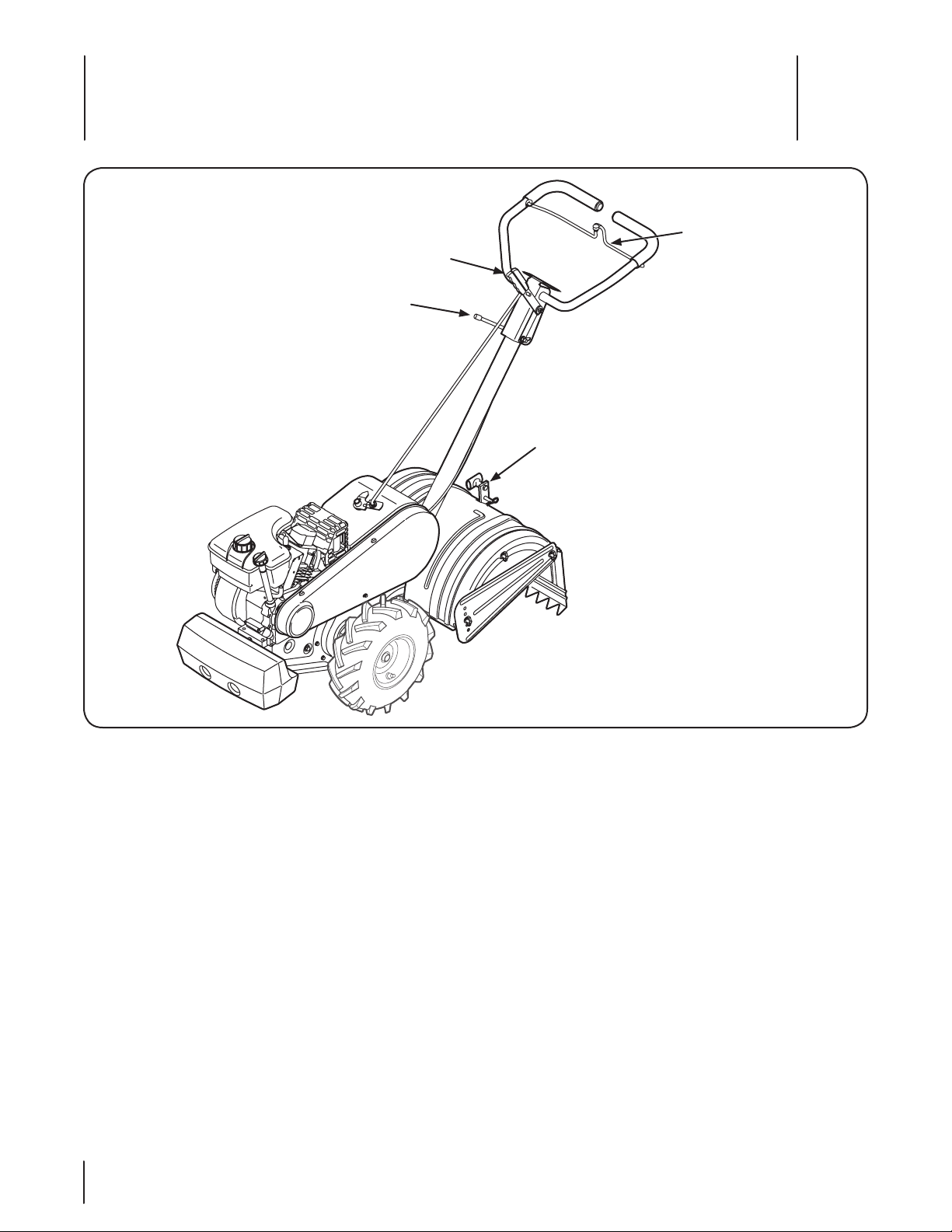
Depth
Stake
Clevis
Pin
T-Knob
Flat Washer
Hex Bolt
Hairpin Clip
Assembly & Set-Up
Contents of Carton
One Tiller • One Handlebar Assembly• One Shift Rod•
One Depth Stake• One Operator’s Manual• One Engine Operator’s Manual•
3
Assembly
Unpacking Instructions
NOTE: Reference to the right or left side of the tiller is
determined from the operator’s position behind the machine.
Remove the staples, break the glue on the top flaps, or cut
1.
the tape at the end of the carton and peel along the top
flap to open carton.
Remove the loose parts included with the tiller (i.e.,
2.
operator’s manual, etc.).
Cut the corners and lay the carton down flat.
3.
Remove the packing materials.
4.
Roll or slide the tiller out of the carton. Check the carton
5.
thoroughly for loose parts.
Extend the control cable and lay it on the floor. Be careful
6.
not to bend or kink the control cable.
NOTE: This tiller is shipped without gasoline or oil in the engine.
Be certain to service engine with gasoline and oil as instructed
in the separate Engine Operator’s Manual before operating your
machine.
Depth Stake
WARNING! Disconnect the spark plug wire and
ground it against the engine to prevent unintended
starting.
Tip the tiller forward so that it rests on the front
1.
counterweight.
Unthread the T-knob from the top of the depth stake and
2.
remove the flat washer and hex bolt. Remove the hairpin
clip from the clevis pin. See Fig. 3-1.
6
Figure 3-1
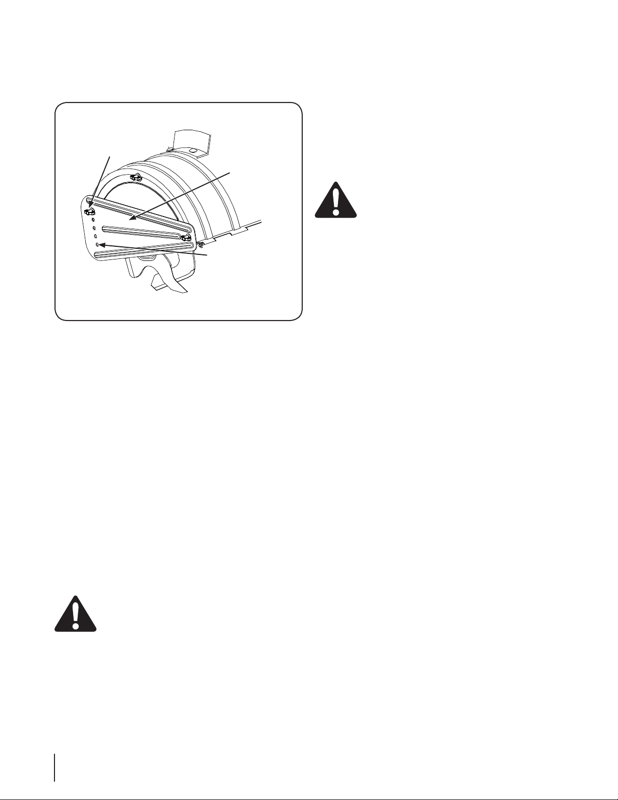
Raise the tine shield hinge flap assembly and insert the
3.
depth stake assembly into the slot — under the tine shield
— and up through the tine shield assembly.
Insert the clevis pin through the tine shield and depth
4.
stake assemblies. Secure it with the hairpin clip.
Insert a hex bolt into the top hole of the depth stake
5.
assembly. Place the flat washer on the hex bolt and thread
the T-knob onto the hex bolt. Tighten securely. See Fig. 3-1.
Tip the tiller back down so that it rests on the tines.
6.
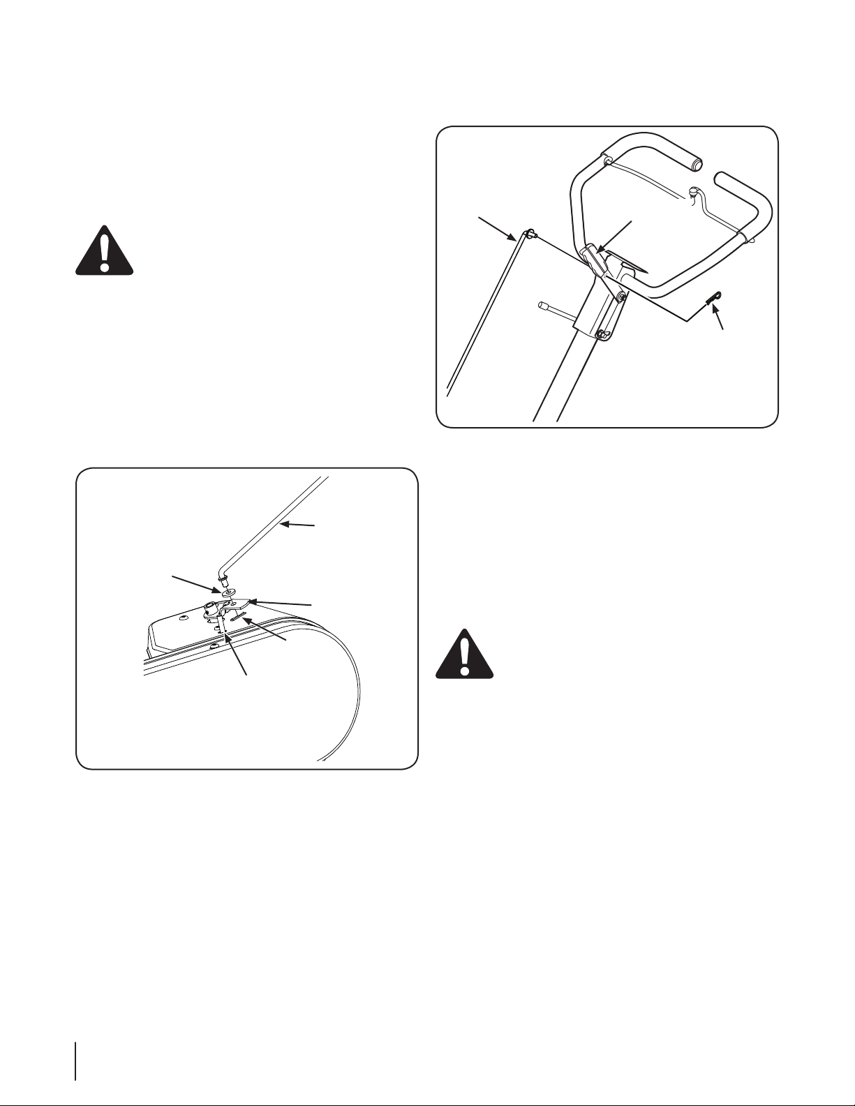
Page 7

Handle
Bolts
Handle
Assembly
Handle
Bracket
Slot-Head
Screw, Nut
& Flat Washers
Internally
Threaded Tube
Plastic Fitting
Clutch Control
Slot Head Screw
Flat Washers
Nut
Nut
Internally
Threaded
Tube
Threaded
Eyebolt
Remove the top two bolts and flange lock nuts from the
1.
handle mounting brackets, but do not remove the bottom
bolt and nut. See Fig. 3-2.
Figure 3-2
Place the handle assembly in position between the handle
2.
mounting brackets.
Line up the holes in the handle with the holes in the
3.
bracket and secure it with hardware previously removed.
Clutch Cable
Attach the clutch cable to the handle as follows: (be careful not
to kink the cable)
Remove the threaded eyebolt and nut from the cable end.
1.
Route the clutch cable to the right side of the handle
2.
mounting brackets and underneath the handle.
Push the cable through the hole in the center of the handle
3.
and snap into the plastic fitting. See Fig. 3-3.
Figure 3-3
Remove the slot head screw, nut, and two flat washers
4.
from the clutch bail. See Fig. 3-4.
Figure 3-4
7sectiOn 2 — asseMbly & set-up
Page 8
Fasten the threaded eyebolt onto the bail by securing it
Control Rod
Indicator Bracket
Rubber Washer
Idler Puller Rod
Hairpin Clip
Control
Rod
Gear Selector
Handle
Hairpin
Clip
5.
from the top with the slot head screw, flat washers and lock
nut.
Thread the eyebolt and nut removed earlier into the
6.
internally threaded tube at the end of the cable. Thread
engagement should be about ⁄”. Tighten the nut against
the tube at end of cable. See Fig. 3-4.
NOTE: Do not overtighten the clutch cable. Too much
tension may cause it to break.
WARNING! Be certain to check the clutch cable
adjustment before operating the tiller.
See the Maintenance & Adjustments Section for
7.
instructions on adjusting the clutch belt.
Control Rod
Make sure the handle assembly is in the highest position.
1.
Refer to the Maintenance & Adjustments Section.
Remove hairpin clips from control rod, leave the rubber
2.
washers on the control rod.
Insert the shorter, (angled), end of the control rod through
3.
the indicator bracket on the shift cover and secure with the
hairpin clip that was previously removed. See Fig. 3-5.
Insert the longer end of the control rod through the hole in
4.
the gear selector handle and secure with the hairpin clip.
See Fig. 3-6.
Figure 3-6
Figure 3-5
Adjustments
Clutch
Position the tiller so the front counterweight is against a
1.
solid object, such as a wall. With the gear selection lever
in NEUTRAL, start the engine. Refer to the separate Engine
Operator’s Manual. Standing on the right side of the tiller,
examine the belt (inside the belt cover). It should not be
turning.
WARNING! Do not put your fingers under the belt
cover.
If the belt turns without bail engaged, adjust it by
2.
unthreading the internally threaded tube at the end of
the cable a few turns clockwise (when standing in the
operator’s position) and then retighten the nut against the
tube.
Now move the shift lever to the FORWARD position.
3.
Carefully engage the clutch by lifting the clutch control
4.
bail against the handle. The wheels should spin. If the
wheels do not spin with the thiller in forward, adjust by
unthreading the tube at the end of the cable a few turns
counter-clockwise, when standing in operator’s position.
Then retighten the nut against the tube.
5.
Recheck both adjustments, and readjust as necessary.
6.
NOTE: A secondary cable adjustment is available if you
reach the point that additional adjustment is needed.
Remove the belt cover and move the hex nuts at the other
end of the cable towards the end of the casing. Then
readjust the hex nuts at the handle.
8 sectiOn 2— asseMbly & set-up
Page 9

Set-Up
Tires
The tires on the tiller may be over-inflated for shipping
purposes. Reduce the tire pressure before operating the
tiller. Recommended operating tire pressure is approximately
20 PSI (check the sidewall of the tire for the manufacturer’s
recommended pressure). Be sure that both tires are inflated
equally or the tiller will pull to one side.
Gas & Oil Fill-Up
Service the engine with gasoline and oil as instructed in the
separate Engine operator’s Manual packed with your tiller. Read
the instructions carefully.
WARNING! Use extreme care when handling
gasoline. Gasoline is extremely flammable and the
vapors are explosive. Never fuel the machine
indoors or while the engine is hot or running.
9sectiOn 2 — asseMbly & set-up
Page 10
Gear Selection Handle
Handle Adjustment Lock
Clutch Control
Depth Stake
Controls and Features
4
Engine Controls
See the separate Engine Operator’s Manual for additional
information and functions of the engine controls.
Gear Selection Handle
The gear selection handle is located in the center of the handle
on the tiller. It is used to select NEUTRAL, REVERSE, or one of the
FORWARD modes.
Clutch Control
The clutch control is located beneath the handle. Squeezing the
clutch control against the handle engages the wheel and tine
drive mechanisms.
Handle Adjustment Lock
The handle may be adjusted to the height desired. Loosen the
handle height adjustment lock a few turns. Pivot handle up or
down to desired position and tighten the lock.
10
Figure 4-1
Throttle Control
The throttle control lever is located on the engine. It controls the
engine speed and stops the engine.
Choke Lever (If Equipped)
The choke lever is located by the throttle. It is used to enrich the
fuel mixture in the carburetor when starting a cold engine.
Primer Button (If Equipped)
The primer button is located behind the air cleaner. It is used to
enrich the fuel mixture in the carburetor when starting a cold
engine.
Depth Stake
The depth stake controls the tilling depth. Refer to the Operation
Section.
Page 11

Use This Position
the First Time
Clevis
Pin
Transportation
Position
1”
3”
5”
7”
Operation
5
Starting the Engine
WARNING! Read, understand, and follow all
instructions and warnings on the machine and in
this manual before operating.
NOTE: When pushing the tiller with the engine off, you will hear
a ratcheting sound or gear noise this is normal.
WARNING! Be sure no one is standing in front of
the tiller while the engine is running or being
started.
1.
Place the gear selection lever in NEUTRAL.
2.
Place the throttle control lever in FAST position or if
equipped, place the engine speed control in the START
position.
3.
Move the choke lever to CHOKE position or if equipped,
push the primer two (2) or three (3) times. Wait about two
(2) seconds between each push.
NOTE: A warm engine may not require choking or priming.
4.
Stand at the side of the tiller. Grasp the starter handle and
pull it out slowly, until it pulls slightly harder. Let the rope
rewind slowly.
5.
Pull the starter handle rapidly. Do not allow the handle to
snap back. Allow it to rewind slowly while keeping a firm
hold on the starter handle.
6.
Repeat the previous steps until the engine starts.
7.
As the engine warms up and begins to operate evenly,
move the choke lever gradually to the RUN position. If the
engine falters, return to the choke position, then slowly
move to the RUN position.
8.
Refer to the Engine Operator’s Manual for additional
engine information.
NOTE: After starting and prior to using the tiller for the
first time, be certain to check the clutch adjustment as
described in Maintenance & Adjustments Section.
Setting The Depth
Tilling depth is controlled by the depth stake which can be
adjusted to five different settings. Adjust the side shields as you
adjust the depth stake.
WARNING! Be certain spark plug wire is
disconnected and grounded against the engine
when performing any adjustments.
When using the tiller for the first time, use the second
1.
adjustment hole from the top (1” of tilling depth). See Fig.
5-1.
Figure 5-1
Stopping the Engine
1.
2.
Move the throttle control to the STOP or OFF position.
Disconnect the spark plug wire and ground it to prevent
accidentally starting the equipment while is is unattended.
NOTE: After the first ten hours of operation, recheck the
clutch adjustment. Refer to Clutch adjustment in the
Assembly & Set Up Section.
11
Page 12
When breaking up sod and for shallow cultivation, use the
Use This Hole for
Lowest/Shallowest
Position
Side Shield
Use this Hole for
Highest/Deepest
Position
2.
setting which gives 1” of tilling depth (second hole from
the top). Place the side shields in their lowest position. See
Fig. 5-2.
Figure 5-2
For further depth, raise the depth stake and side shields
3.
and also make one or two more passes over the area.
When tilling loose soil, the depth stake may be raised to its
4.
highest position (use the bottom adjustment hole) to give
the deepest tilling depth. Raise the side shields to their
highest position.
To transport the tiller, lower the depth stake and use the
5.
top adjustment hole.
To adjust the depth stake, remove the clevis pin and
6.
hairpin clip. Move the depth stake to the desired setting
and secure with the clevis pin and hairpin clip. See Fig. 5-1.
To adjust the side shields, remove the wing nuts. Move the
7.
side shield to the desired position and replace the wing
nuts. Tighten securely.
NOTE: Use the reverse tine drive when tilling virgin
ground, sod, or hard soil. Use the forward tine drive when
cultivating or tilling soft ground.
Squeeze the clutch handle against the handle to engage
5.
the wheels and tines.
NOTE: Make certain the gear selection indicator is correctly
positioned before engaging the clutch handle. If it is
between the gears, the engine will stall.
To transport the tiller, do not engage the tines. Select the
6.
wheel drive only.
WARNING! Do not push down on the handles so
that the wheels are lifted off the ground while using
the tine drive, or the tiller could move backward and
cause personal injury.
For best results, it is recommended the garden be tilled
7.
twice (lengthwise, then width-wise) to pulverize the soil.
Operating the Tiller
Select the depth stake setting.
1.
Start the engine as instructed on the previous page.
2.
Move the gear selection handle to one of the forward
3.
modes or reverse.
WARNING! Do not move the gear selection handle
4.
12 sectiOn 5— OperatiOn
with the wheels or tines engaged. Make certain the
tiller is stopped completely before changing the
gear selection. A partial engagement may be
necessary when engaging tines.
To shift into forward wheels and tine drive, push forward
slightly on the gear selection handle and slowly engage
the clutch control allowing the gears to synchronize. To
stop forward movement and tine drive, release the clutch
control. Do not shift gears with the clutch control engaged
except when engaging the tines.
Page 13

Maintenance & Adjustments
6
WARNING! Disconnect the spark plug wire and
ground it against the engine before performing any
maintenance or repairs.
Maintenance
Engine
Refer to the separate Engine Operator’s Manual for engine
maintenance instructions.
Tire Pressure
Check the tire pressure in both tires. Deflate or inflate both
tires evenly to 20 PSI. Be sure that both tires have the same air
pressure or the tiller will pull to one side.
Air Cleaner
Service the air cleaner every 10 hours under normal conditions.
Clean it every hour under extremely dusty conditions. Poor
engine performance or flooding usualy indicates that the air
cleaner should be serviced. Refer to the Engine Operator’s
Manual for maintenance instructions.
Tines
Clean the underside of the tine shield after each use. The dirt
washes off the tines easier if rinsed off immediately instead of
after it dries. Always towel dry the tiller afterwards and apply a
light coat of oil or silicone to prevent rusting or water damage.
NOTE: Never use a “pressure washer” to clean your tiller. Water
can penetrate tight areas of the tiller and its chain case and cause
serious damage to the tiller.
Lubrication
Transmission
The transmission is pre-lubricated and sealed at the factory. It
requires no checking unless the transmission is disassembled. To
fill with grease, lay the right half of the transmission on its side,
add 22 ounces of Benalene 920 grease, and assemble the left
half to it. This grease can be obtained at your nearest authorized
dealer by ordering part number 737-0300.
Wheel Shafts
Remove wheel assemblies and lubricate the axle shafts at least
once a season.
Adjustments
Belt Tension
WARNING! Never attempt to make any
adjustments while the engine is running, except
where specified in the operator’s manual.
Periodic adjustment of the belt tension may be required due to
normal stretch and wear on the belt. Adjustment is needed if the
tines or wheels seem to hesitate while turning, but the engine
maintains the same speed.
To adjust the tension on the belt, refer to Clutch adjustment in
Assembly & Set-Up Section.
After the belt tension has been adjusted, if the belt is excessively
stretched, you may need to adjust the idler pulley rod. This can
easily be checked.
With the engine off and the clutch control bail disengaged, shift
the gear selection handle to each forward mode. If the indicator
bracket touches the idler pulley rod — with the clutch control
bail disengaged — then an adjustment is necessary.
Disconnect and ground out spark plug wire against the
1.
engine.
Remove the belt cover as described under Belt
2.
Replacement in the Service Section.
Remove the hairpin clip and spring washer from the idler
3.
pulley rod.
Move the idler pulley rod to the lower hole in the idler
4.
bracket.
Replace the spring washer and hairpin clip.
5.
Check clearance of the idler pulley rod to the indicator
6.
bracket by shifting to each forward mode, as before.
Clutch Handle
Lubricate the pivot point on the clutch handle and the cable at
least once a season with light oil. The control must operate freely
in both directions.
Pivot Points
Lubricate all pivot points and linkages at least once a season with
light oil.
Tine Shafts
Remove tine assemblies and lubricate the tine shafts at least
once a season.
13
Page 14

Off-Season Storage
If the tiller will not be used for a period longer than 30 days, the
following steps should be taken to prepare the tiller for storage.
Clean the exterior of the engine and the entire tiller
•
thoroughly. Lubricate the tiller as described in the
lubrication instructions.
We do not recommend the use of pressure washers to
•
clean your tiller. They may cause damage to electric
components, spindles, pulleys, bearings or the engine. The
use of pressure washers will result in shortened life and
reduce serviceability.
Refer to the Engine Operator’s Manual for correct engine
•
storage instructions.
Wipe the tines with an oiled rag to prevent rust.
•
Store tiller in a clean, dry area. Do not store next to
•
corrosive materials, such as fertilizer.
NOTE: When storing any type of power equipment in an
unventilated area or metal storage shed, care should be taken
to rustproof the equipment. Using a light oil or silicone, coat the
equipment and especially any springs, bearings, and cables.
14 sectiOn 6— Maintenance & adjustMents
Page 15

Torx Screws
Belt Cover
Hex Cap Nut &
Flat Washer
Self-Tapping
Screw
Idler Pulley Rod
Engine Pulley
Belt Keeper
Bracket
Idler Bracket
Service
Belt Replacement
Your tiller has been engineered with a belt made of special
material (Kevlar Tensile) for longer life and better performance. It
should not be replaced with an off-the-shelf belt. Order all belts
through your authorized service dealer.
Disconnect and ground the spark plug wire against the
1.
engine.
Remove the belt cover from the left side of the tiller by
2.
remove the two torx screws from the top of the belt cover.
See Fig. 7-1.
Remove the belt keeper bracket located behind the engine
4.
pulley by removing the two hex bolts and lock washers.
See Fig. 7-2.
7
Figure 7-1
Remove the hex cap nut and flat washer from the side of
3.
the belt cover and remove the self-tapping screw at the
bottom of the front of the cover.
Figure 7-2
Remove the belt and replace with a new one. Follow the
5.
instructions in reverse order to reassemble.
NOTE: Make certain the belt is routed over the idler pulley
and inside of the belt keepers by the engine pulley. See Fig.
7-2.
15
Page 16

Troubleshooting
Problem Cause Remedy
8
Engine fails to start Fuel tank empty, or stale fuel.
Engine runs erratic Tiller running on CHOKE.
Engine overheats Engine oil level low.
Tines do not engage Foreign object lodged in tines.
Tines skip over ground Improper rotation.1. Forward rotation should only be used on soil
Wheels do not engage Clevis pin missing.
1.
Throttle control lever not in correct starting
2.
position (if equipped).
Blocked fuel line.
3.
Dirty air cleaner.
4.
Choke not in ON position.
5.
Spark plug wire disconnected.
6.
Faulty spark plug.
7.
Engine flooded.
8.
1.
Spark plug wire loose.
2.
Blocked fuel line or stale fuel.
3.
Vent in gas cap plugged.
4.
Water or dirt in fuel system.
5.
Dirty air cleaner.
6.
Carburetor out of adjustment.
7.
1.
Dirty air cleaner.
2.
Air flow restricted.
3.
Carburetor not adjusted properly.
4.
1.
Tine clevis pin(s) missing.
2.
Pulley and idler not in correct adjustment.
3.
Not shifting properly.
4.
Control cable not adjusted properly.
5.
Belt worn and/or stretched.
6.
1.
Tiller is not being shifted properly.
2.
Control cable not adjusted properly.
3.
Belt worn and/or stretched.
4.
Fill tank with clean, fresh gasoline.
1.
Move throttle lever to start position.
2.
Clean fuel line.
3.
Refer to the Engine Operator’s Manual
4.
Move switch to ON position.
5.
Connect wire to spark plug.
6.
Clean, adjust gap or replace.
7.
Refer to the Engine Operator’s Manual
8.
Move choke lever to OFF position.
1.
Connect and tighten spark plug wire.
2.
Clean fuel line; fill tank with clean, fresh
3.
gasoline.
Clear vent.
4.
Drain fuel tank. Refill with fresh fuel.
5.
Refer to the Engine Operator’s Manual
6.
Refer to the Engine Operator’s Manual
7.
Fill crankcase with proper oil.
1.
Refer to the Engine Operator’s Manual
2.
Refer to the Engine Operator’s Manual
3.
Adjust carburetor as instructed in the Engine
4.
Operator’s Manual
Dislodge foreign object.
1.
Replace tine clevis pin(s).
2.
Take tiller to authorized service dealer.
3.
Refer to the Operation Section for proper
4.
shifting procedures.
Adjust control cable
5.
Replace belt.
6.
1.
that has already been tilled, not on virgin soil.
Replace clevis pin.
1.
Refer to Operation Section for proper
2.
shifting procedures.
Adjust control cable
3.
Replace belt.
4.
16
Page 17

Replacement Parts
Component Part Number and Description
9
754-0434, Drive Belt, 4LX58.16 LG
742-0305, Articulating Tine
746-1117, Drive Cable
734-0808, Tires
17211-ZL8-023, Air Filter
98079-56846, Spark Plug
Phone (800) 800-7310 to order replacement parts or a complete Parts Manual (have your full model number and serial number ready).
Parts Manual downloads are also available free of charge at www.mtdproducts.com.
17
Page 18

Notes
11
18
Page 19

19sectiOn 11 — nOtes
Page 20

CUB CADET LLC
MANUFACTURER’S LIMITED WARRANTY FOR
EDGERS, STRING TRIMMERS & TILLERS
The limited warranty set forth below is given by Cub Cadet LLC with
respect to new merchandise purchased and used in the United States,
its possessions and territories, and by MTD Products Limited with
respect to new merchandise purchased and used in Canada and /or its
territories and possessions.
“Cub Cadet” warrants this product (excluding its Normal Wear Parts
as described below) against defects in material and workmanship
for a period of three (3) years commencing on the date of original
purchase and will, at its option, repair or replace, free of charge, any
part found to be defective in materials or workmanship. This limited
warranty shall only apply if this product has been operated and
maintained in accordance with the Operator’s Manual furnished with
the product, and has not been subject to misuse, abuse, commercial
use, neglect, accident, improper maintenance, alteration, vandalism,
theft, fire, water, or damage because of other peril or natural disaster.
Damage resulting from the installation or use of any part, accessory
or attachment not approved by Cub Cadet for use with the product(s)
covered by this manual will void your warranty as to any resulting
damage.
Normal Wear Parts are warranted to be free from defects in material
and workmanship for a period of thirty (30) days from the date of
purchase. Normal wear parts include, but are not limited to items
such as: batteries, belts, blades, tines, wheels and tires.
HOW TO OBTAIN SERVICE: Warrant y ser vice is available, WIT H
PROOF OF PURCHASE, through your local authorized service
dealer. To locate the dealer in your area:
In the U.S. A.
To locate the dealer in your area, check your Yellow Pages, or contact
Cub Cadet LLC at P.O. Box 361131, Cleveland, Ohio 44136-0019, or
call 1-877-282-8684, or log on to our Web site at www.cubcadet.
com.
In Canada
Cont act MTD Products Limited, Kitchener, ON N2G 4J1, or call
1-800-668-1238 or log on to our Web si te at www.m tdcanada.
com.
This limited warranty does not provide coverage in the following
cases:
a. The engine or component parts thereof. These items may
carry a separate manufacturer’s warranty. Refer to applicable
manufacturer’s warranty for terms and conditions.
b. Routine maintenance items such as lubricants, filters, blade
sharpening, tune-ups, brake adjustments, clutch adjustments,
deck adjustments, and normal deterioration of the exterior finish
due to use or exposure.
c. Cub Cadet does not extend any warranty for products sold or
exported outside of the United States and/or Canada, and their
respective possessions and territories, except those sold through
Cub Cadet’s authorized channels of export distribution.
d. Replacement parts that are not genuine Cub Cadet parts.
e. Service completed by someone other than an authorized service
dealer.
f. Transportation charges and service calls.
g. Cub Cadet does not warrant this product for commercial use.
No implied warranty, including any implied warranty of
merchantability of fitness for a particular purpose, applies after
the applicable period of express written warranty above as to the
parts as identified. No other express warranty, whether written or
oral, except as mentioned above, given by any person or entity,
including a dealer or retailer, with respect to any product, shall
bind Cub Cadet. During the period of the warrant y, the exclusive
remedy is repair or replacement of the product as set forth above.
The provisions as set for th in this warranty provide the sole and
exclusive remedy arising from the sale. Cub Cadet shall not be
liable for incidental or consequential loss or damage including,
without limitation, expenses incurred for substitute or replacement
lawn care services or for rental expenses to temporarily replace a
warranted product.
Some states do not allow the exclusion or limitation of incidental
or consequential damages, or limitations on how long an implied
warranty lasts, so the above exclusions or limitations may not apply
to you.
In no event shall recovery of any kind be greater than the amount of
the purchase price of the product sold. Alteration of safety features of
the product shall void this warranty. You assume the risk and liability
for loss, damage, or injury to you and your proper ty and/or to others
and their property arising out of the misuse or inability to use the
product.
This limited warranty shall not ex tend to anyone other than the
original purchaser or to the person for whom it was purchased as a
gift.
HOW STATE LAW RELATES TO THIS WARRANTY: This limited
warranty gives you specific legal rights, and you may also have other
rights that vary in different jurisdictions.
IMPORTANT: Owner must present Original Proof of Purchase to
obtain warranty coverage.
Cub Cadet LLC, P.O. BOX 361131 CLEVELAND, OHIO 44136-0019; Phone: 1-877-282-8684
GDOC-100087 REV. A
MTD Canada Limited - KITCHENER, ON N2G 4J1; Phone 1-800-668-1238
Page 21

Medidas importantes de seguridad • Conguración • Funcionamiento • Mantenimiento • Servicio •
Solución de problemas • Garantía
Manual del OperadOr
Cultivadora de Dientes Traseros — Modelo RT 65
LEA Y SIGA TODAS LAS INSTRUCCIONES DE ESTE MANUAL ANTES DE PONER EN
SI NO RESPETA ESTAS INSTRUCCIONES PUEDE PROVOCAR LESIONES PERSONALES.
CUB CADET LLC, P.O. BOX 361131 CLEVELAND, OHIO 44136-0019
Impreso en Estados Unidos de América
ADVERTENCIA
FUNCIONAMIENTO ESTA MÁQUINA.
Formulario No. 769-03598
(Octubre 31, 2007)
Page 22

Al propietario
Gracias
Gracias por comprar una Cultivadora fabricada por Cub
Cadet LLC LLC. La misma ha sido diseñada cuidadosamente
para brindar excelente rendimiento si se la opera y mantiene
correctamente.
Por favor lea todo este manual antes de operar el equipo.
Le indica cómo configurar, operar y mantener la máquina
con seguridad y fácilmente. Por favor asegúrese de seguir
cuidadosamente y en todo momento las prácticas de seguridad
recomendadas, y hacérselas seguir a cualquier otra persona que
opere la máquina. En caso de no hacerlo podrían producirse
lesiones personales o daños materiales.
Toda la información contenida en este manual hace referencia
a la más reciente información de producto disponible en el
momento de la impresión. Revise el manual frecuentemente
para familiarizarse con la unidad, sus características y
funcionamiento. Por favor tenga en cuenta que este Manual
del Operador puede cubrir una gama de especificaciones de
productos de diferentes modelos. Las características y funciones
incluidas y/o ilustradas en este manual pueden no ser aplicables
a todos los modelos. Cub Cadet se reserva el derecho de
1
modificar las especificaciones de los productos, los diseños y el
equipo estándar sin previo aviso y sin generar responsabilidad
por obligaciones de ningún tipo.
Este producto cumple con las estrictas normas de seguridad
del Outdoor Power Equipment Institute y de un laboratorio de
pruebas independiente. Si tiene algún problema o duda respecto
a la unidad, llame a un distribuidor de servicio Cub Cadet
autorizado o póngase en contacto directamente con nosotros.
Los números de teléfono, dirección del sitio web y dirección
postal de la Asistencia al Cliente de Cub Cadet se encuentran en
esta página. Queremos garantizar su entera satisfacción en todo
momento.
En este manual, las referencias al lado derecho o izquierdo de la
máquina se observan desde la posición del operador.
El fabricante del motor es el responsable de todas las
cuestiones relacionadas con el rendimiento, potencia de salida,
especificaciones, garantía y mantenimiento del motor. Para
obtener mayor información consulte el Manual del Propietario /
Operador entregado por el fabricante del motor, que se envía, en
un paquete por separado, junto con su unidad.
Índice
Importante Medidas importantes de seguridad .. 3
Ensamblado y Conguración ................................. 6
Controles y Características ....................................10
Funcionamiento .....................................................11
Registro de información de producto
Antes de configurar y operar su equipo nuevo, por favor localice
la placa del modelo en el equipo y registre la información en
el área situada a la derecha. Para encontrar la placa de modelo,
colóquese detrás de la unidad en la posición del operador y mire
hacia la parte inferior de la sección trasera del chasis. Si tiene
que solicitar soporte técnico a través de nuestro sitio web, el
Departamento de Asistencia al Cliente, o de un distribuidor de
servicio autorizado local, necesitará esta información.
Mantenimiento y Ajustes .......................................13
Servicio ....................................................................15
Solución de Problemas ..........................................16
Garantía ...................................... Cubierta posterior
núMerO de MOdelO
núMerO de serie
Asistencia al Cliente
Por favor, NO devuelva la unidad al minorista o distribuidor sin ponerse en contacto primero con el Departamento de
Asistencia al Cliente.
En caso de tener problemas para montar este producto o de tener dudas con respecto a los controles, funcionamiento o
mantenimiento del mismo, puede solicitar la ayuda de expertos. Elija entre las opciones que se presentan a continuación:
Visite nuestro sitio web en www.cubcadet.com
◊
Llame a un representante de Asistencia al Cliente al (800) 965-4CUB
◊
Escríbanos a Cub Cadet LLC • P.O. Box 361131 • Cleveland, OH • 44136-0019
◊
2
Page 23

Medidas importantes de seguridad
ADVERTENCIA! La presencia de este símbolo indica que se trata de instrucciones
importantes de seguridad que se deben respetar para evitar poner en peligro su seguridad
personal y/o material y la de otras personas. Lea y siga todas las instrucciones de este
manual antes de poner en funcionamiento esta máquina. Si no respeta estas instrucciones
puede provocar lesiones personales.
Cuando vea este símbolo. TENGA EN CUENTA LAS ADVERTENCIAS!
PROPOSICIÓN 65 DE CALIFORNIA
ADVERTENCIA! El escape del motor de este producto, algunos de sus componentes y
algunos componentes del vehículo contienen o liberan sustancias químicas que el estado
de California considera que pueden producir cáncer, defectos de nacimiento u otros
problemas reproductivos.
ADVERTENCIA! Los bornes de la batería y los accesorios afines contienen plomo y
compuestos de plomo, sustancias químicas que según lo establecido por el Estado de
California causan cáncer y daños en el sistema reproductivo. Lávese las manos después de
estar en contacto con estos componentes.
PELIGRO! Esta máquina está diseñada para ser utilizada respetando las normas de
seguridad contenidas en este manual. Al igual que con cualquier tipo de equipo motorizado,
un descuido o error por parte del operador puede producir lesiones graves. Esta máquina es
capaz de amputar dedos (de las manos y/o los pies), manos y pies. De no respetar las
instrucciones de seguridad siguientes se pueden producir lesiones graves o la muerte.
2
Capacitación
Lea, entienda y cumpla todas las instrucciones incluidas en
1.
la máquina y en el(los) manual(es) antes de intentar realizar
el montaje de la unidad y utilizarla. Guarde este manual
en un lugar seguro para consultas futuras y periódicas, así
como para solicitar repuestos.
Familiarícese con todos los controles y con el uso adecuado
2.
de los mismos. Sepa cómo detener la máquina y desactivar
los controles rápidamente.
No permita nunca que los niños menores de 14 años utilicen
3.
esta máquina. Los niños de 14 años en adelante deben
leer y entender las instrucciones de operación y normas
de seguridad contenidas en este manual y en la máquina y
deben ser entrenados y supervisados por un adulto.
Nunca permita que los adultos operen esta máquina sin
4.
recibir antes la instrucción apropiada.
Mantenga el área de operación despejada de personas,
5.
particularmente de niños pequeños y mascotas. Detenga la
máquina si alguien se acerca.
Preparativos
Inspeccione minuciosamente el área donde utilizará el
1.
equipo. Quite las piedras, palos, alambres y otros objetos
extraños con los que se pueda tropezar y provocar lesiones
personales.
Utilice zapatos de trabajo resistentes, de suela fuerte, así
2.
como pantalones y camisas ajustados. Las prendas sueltas
y las alhajas se pueden enganchar en las piezas móviles.
Nunca opere la máquina descalzo o con sandalias.
Antes de arrancar el motor, desenganche las palancas del
3.
embrague y desplácelas (en caso de haber) a la posición
neutral (“N”).
Nunca deje la máquina en funcionamiento sin vigilancia.
4.
Nunca intente realizar ajustes mientras el motor está
5.
en marcha excepto en los casos específicamente
recomendados en el manual del operador.
Manejo seguro de la gasolina:
Para evitar lesiones personales o daños materiales tenga mucho
cuidado cuando trabaje con gasolina. La gasolina es sumamente
inflamable y sus vapores pueden causar explosiones. Si se
derrama gasolina encima o sobre la ropa se puede lesionar
gravemente ya que se puede incendiar. Lávese la piel y cámbiese
de ropa de inmediato.
Utilice sólo los recipientes para gasolina autorizados.
a.
Nunca llene los recipientes en el interior de
b.
un vehículo o camión o caja de remolque con
recubrimiento plástico. Antes de llenarlos, coloque
siempre los recipientes en el suelo y lejos del
vehículo.
3
Page 24

Cuando sea factible, retire el equipo a gasolina del
c.
camión o remolque y llénelo en el suelo. Si esto
no es posible, llene el equipo en un remolque con
un contenedor portátil, en vez de hacerlo con una
boquilla dispensadora de gasolina.
Mantenga la boquilla de llenado en contacto con el
d.
borde del depósito de combustible o con la abertura
del recipiente en todo momento, hasta terminar
la carga. No utilice un dispositivo de boquilla de
apertura/cierre.
Apague todos los cigarrillos, cigarros, pipas y otras
e.
fuentes de combustión.
Nunca cargue combustible en la máquina en un
f.
espacio cerrado.
Nunca saque la tapa de la gasolina ni agregue
g.
combustible mientras el motor está caliente o en
marcha. Deje que el motor se enfríe por lo menos dos
minutos antes de volver a cargar combustible.
Nunca llene en exceso el depósito de combustible.
h.
Llene el tanque no más de ½ pulgada por debajo
de la base del cuello del tapón de carga, para dejar
espacio para la expansión del combustible.
Vuelva a colocar la tapa de la gasolina y ajústela bien.
i.
Limpie el combustible que se haya derramado sobre
j.
el motor y el equipo. Traslade la máquina a otra zona.
Espere 5 minutos antes de encender el motor.
Para reducir el riesgo de incendio, mantenga la
k.
máquina limpia de pasto, hojas y de acumulación
de otros residuos. Limpie los derrames de aceite o
combustible y saque todos los residuos embebidos
en combustible.
Nunca guarde la máquina o el recipiente de
l.
combustible en un espacio cerrado donde haya
fuego, chispas o luz piloto, como por ejemplo de
calentadores de agua, calefactores de ambientes,
hornos, secadores de ropa u otros aparatos a gas.
Funcionamiento
No coloque las manos ni los pies cerca de las piezas
1.
giratorias. El contacto con la piezas giratorias puede resultar
en la amputación de manos o pies.
No utilice la máquina bajo la influencia del alcohol o las
2.
drogas.
Nunca opere esta máquina sin buena visibilidad o
3.
iluminación. Siempre debe estar seguro de que está bien
afirmado y sujetando firmemente las manijas.
Mantenga a los transeúntes alejados de la máquina mientras
4.
la misma está en funcionamiento. Detenga la máquina si
alguien se acerca.
Tenga cuidado cuando labre tierras duras. Los dientes
5.
pueden clavarse en la tierra e impulsar la cultivadora
hacia adelante. Si esto ocurre, suelte el manubrio y deje la
máquina libre.
Sea sumamente precavido cuando opere la máquina sobre
6.
una superficie con grava o cuando la cruce. Manténgase
alerta por si se presentan peligros ocultos o tránsito. No
transporte pasajeros.
Nunca utilice la máquina a altas velocidades de
7.
desplazamiento sobre superficies duras o resbaladizas.
Tenga cuidado para evitar resbalar o caerse.
8.
Mire hacia abajo y hacia atrás y tenga cuidado cuando se
9.
desplace en marcha atrás o cuando jale de la máquina hacia
usted.
Arranque el motor de acuerdo con las instrucciones del
10.
manual y mantenga los pies alejados de los dientes en todo
momento.
Después de golpear con algún objeto extraño, detenga el
11.
motor, desconecte el cable de la bujía y conecte el motor a
masa. Inspeccione minuciosamente la máquina para ver si
está dañada. Repare el daño antes de arrancar y utilizar la
máquina.
Desenganche todas las palancas de embrague (en caso
12.
de haber) y detenga el motor antes de dejar la posición
de operación (detrás de las manijas). Espere hasta que los
dientes se detengan completamente antes de limpiarlos,
hacer algún ajuste o inspeccionarlos.
Nunca encienda el motor en espacios cerrados o en una
13.
zona con poca ventilación. El escape del motor contiene
monóxido de carbono, un gas inodoro y letal.
El silenciador y el motor se calientan y pueden causar
14.
quemaduras. No los toque.
Tenga precaución cuando labre terreno cerca de vallas,
15.
edificios y servicios subterráneos. Los dientes rotatorios
pueden causar daños materiales o lesiones personales.
No sobrecargue la capacidad de la máquina intentando
16.
labrar el suelo a un nivel demasiado profundo o a una
velocidad demasiado rápida.
Si la máquina arranca haciendo un sonido o una vibración
17.
rara, detenga el motor, desconecte el cable de la bujía y
conéctelo a masa contra el motor. Inspeccione la máquina
minuciosamente para ver si está dañada. Repare todos los
daños antes de encender y operar la máquina.
Mantenga todos los escudos, protectores y dispositivos de
18.
seguridad en su lugar y en correcto funcionamiento.
Nunca levante o transporte la máquina cuando el motor
19.
está encendido.
Use sólo aditamentos y accesorios aprobados por el
20.
fabricante. Si no lo hace, pueden producirse lesiones
personales.
Si se presentan situaciones que no están previstas en este
21.
manual, tenga cuidado y use el sentido común. Póngase en
contacto con Asistencia al Cliente para solicitar ayuda y el
nombre del distribuidor de servicio más cercano.
Mantenimiento y Almacenamiento
Mantenga la máquina, los aditamentos y accesorios en
1.
condiciones de funcionamiento seguro.
Deje que la máquina se enfríe por lo menos cinco minutos
2.
antes de guardarla. Nunca altere los dispositivos de
seguridad. Controle periódicamente que funcionen
correctamente.
Controle frecuentemente que todos los pernos y tornillos
3.
estén bien ajustados para comprobar que la máquina se
encuentra en condiciones seguras de funcionamiento.
Además, haga una inspección visual de la máquina para
verificar si está dañada.
Antes de limpiar, reparar o inspeccionar la máquina,
4.
detenga el motor y asegúrese de que los dientes y todas
las partes móviles se hayan detenido. Desconecte el cable
de la bujía y póngalo haciendo masa contra el motor para
evitar que se encienda accidentalmente.
No cambie la configuración del regulador del motor ni lo
5.
opere a sobrevelocidad. El regulador del motor controla la
velocidad máxima de funcionamiento seguro del motor.
Mantenga o reemplace las etiquetas de seguridad e
6.
instrucciones según sea necesario.
Siga las instrucciones de este manual para cargar,
7.
descargar, transportar y almacenar de manera segura esta
máquina.
Si la máquina se va a almacenar por un período
8.
prolongado, consulte siempre el manual del operador para
ver los detalles importantes que sean necesarios.
4 sectiOn 2 — Medidas iMpOrtantes de seguridad
Page 25

9.
Si debe vaciar el tanque de combustible, hágalo al aire
libre.
10.
Respete las normas referentes a la disposición correcta de
residuos y las reglamentaciones sobre gasolina, aceite, etc.
para proteger el medio ambiente.
Aviso referido a emisiones
Los motores que están certificados y cumplen con las
regulaciones de emisiones federales EPA y de California para
SORE (Equipos pequeños todo terreno) están certificados para
operar con gasolina común sin plomo y pueden incluir los
siguientes sistemas de control de emisiones: Modificación de
motor (EM) y catalizador de tres vías (TWC) si están equipados de
esa manera.
Amortiguador de chispas
ADVERTENCIA! Esta máquina está equipada con
un motor de combustión interna y no debe ser
utilizada en un terreno agreste cubierto por bosque,
malezas o hierba ni cerca del mismo excepto que el
sistema de escape del motor esté equipado con un
amortiguador de chispas que cumpla con las leyes
locales o estatales correspondientes (en caso de
haber).
Si se utiliza un amortiguador de chispas el operador lo debe
mantener en condiciones de uso adecuadas. En el Estado
de California las medidas anteriormente mencionadas son
exigidas por ley (Artículo 4442 del Código de Recursos Públicos
de California). Es posible que existan leyes similares en otros
estados. Las leyes federales se aplican en territorios federales.
Puede conseguir el amortiguador de chispas para el silenciador
a través de su distribuidor de mantenimiento de motores
autorizado más cercano o poniéndose en contacto con el
departamento de servicios, Apartado Postal 361131 Cleveland,
Ohio 44136-0019.
Vida útil media
Según la Comisión de Seguridad de Productos para el
Consumidor de los Estados Unidos (CPSC) y la Agencia de
Protección Ambiental de los Estados Unidos (EPA), este
producto tiene una vida útil media de siete (7) años ó 130 horas
de funcionamiento. Al finalizar la vida útil media, adquiera una
máquina nueva o haga inspeccionar anualmente esta unidad
por un distribuidor de servicio autorizado para cerciorarse de
que todos los sistemas mecánicos y de seguridad funcionan
correctamente y no tienen excesivo desgaste. Si no lo hace,
pueden producirse accidentes, lesiones o la muerte.
ADVERTENCIA! Su responsabilidad—Restrinja el uso de esta máquina motorizada a las personas que lean,
comprendan y respeten las advertencias e instrucciones que figuran en este manual y en la máquina.
GUARDE ESTAS INSTRUCCIONES
5sectiOn 2 — Medidas iMpOrtantes de seguridad
Page 26

Estaca de
profundidad
Chaveta de
horquilla
Perilla en “T”
Arandela plana
Perno hexagonal
Broche de
horquilla
Montaje y Configuración
El Contenido del Cartón
Un Cultivadora• Un Unidad de la Manija• Un Varilla de control•
Un Depth Stake• Un Manual de Operario• Un Manual de Operario de Motor•
3
Montaje
Desembalar Instrucciones
NOTA: Las referencias al lado derecho o izquierdo de la
cultivadora se determinan desde la parte posterior de la unidad
en la posición de operación.
Saque las grapas, rompa el pegamento de las aletas
1.
superiores o corte la cinta del extremo de la caja y tire a lo
largo de la aleta superior para abrirla.
Quite las partes sueltas que se incluyen con su unidad (por
2.
ejemplo, el manual del operador, etc.).
Corte a lo largo de las esquinas, extienda la caja plana hacia
3.
abajo.
Retire el material de empaque.
4.
Deslice la unidad hasta sacarla de la caja de cartón. Revise
5.
minuciosamente la caja para detectar la presencia de
piezas sueltas.
Estire el cable de control y extiéndalo en el piso. Tenga
6.
cuidado de no doblar ni torcer el cable de control.
NOTA: Esta unidad se envía sin gasolina ni aceite en el motor.
Antes de operar la máquina cargue el motor con gasolina y aceite
como se indica en el manual del motor por separado.
Estaca de profundidad
ADVERTENCIA! Desconecte el cable de la bujía y
póngalo haciendo masa contra el motor para evitar
que se encienda accidentalmente.
Incline la cultivadora hacia adelante hasta que descanse
1.
sobre el contrapeso frontal.
Desenrosque la perilla en “T” de la parte superior de la
2.
estaca de profundidad y retire la arandela plana y el perno
hexagonal. Saque el broche de horquilla de la chaveta de
horquilla. Vea la Fig. 3-1.
6
Figura 3-1
Levante el montaje de la aleta con bisagras del protector
3.
de dientes e inserte el montaje de la estaca de profundidad
en la ranura (debajo del protector) y para arriba por el
montaje protector de dientes.
Inserte la chaveta de horquilla en los montajes del
4.
protector de dientes y de la estaca de profundidad.
Asegure con el broche de horquilla.
Inserte un perno hexagonal en el orificio superior del
5.
montaje de la estaca de profundidad. Coloque la arandela
plana sobre el perno hexagonal y enrosque la perilla en “T”
en el perno. Ajuste bien. Vea la Fig. 3-1.
Incline la cultivadora hacia atrás nuevamente hasta que
6.
descanse sobre los dientes.
Page 27

Manija
Perno
Unidad
de
la manija
Soporte
de la
manija
Tornillo cabeza
ranurada,
tuerca y arandelas
planas
Tubo con rosca
interna
Accesorio
plástico
Control de
embrague
Tornillo cabeza ranurada
Arandelas
planas
Tuerca
Tuerca
Tubo con
rosca
interna
Perno de ojo
roscado
Retire los dos pernos superiores y las tuercas de seguridad
1.
con reborde de los soportes de montaje de la manija, pero
no retire el perno y la tuerca inferiores. Vea la Fig. 3-2.
Figura 3-2
Posicione la unidad de la manija entre los soportes de
2.
montaje de la manija.
Haga coincidir los orificios de la manija con los orificios del
3.
soporte y fije con los accesorios previamente extraidos.
Cable del Embrague
Fije el cable del embrague a la manija de la siguiente manera:
(tenga cuidado de no torcer el cable))
Quite el perno de ojo roscado y la tuerca del extremo del
1.
cable.
Conduzca el cable del embrague por el lado derecho de
2.
los soportes de montaje de la manija y por debajo de la
manija.
Empuje el cable a través del orificio del centro de la manija
3.
e introduzca a presión el accesorio plástico. Vea la Fig. 3-3.
Figura 3-3
Retire el tornillo de cabeza ranurada, la tuerca y las dos
4.
arandelas planas del gancho del embrague. Vea la Fig. 3-4.
Figura 3-4
7sección 3 — MOntaje y cOnfiguración
Page 28

Fije el perno de ojo roscado al gancho sujetándolo desde
Varilla de
control
Soporte del
indicador
Arandela de
goma
Broche de horquilla
Varilla de la
polea loca
Varilla de
control
manija
selectora de
cambios
Broche de
horquilla
5.
arriba con el tornillo de cabeza ranurada, las arandelas
planas y la tuerca de seguridad.
Enrosque el perno de ojo y la tuerca que quitara
6.
anteriormente en el tubo con rosca interna que está en el
extremo del cable. Debe enroscar un trozo de alrededor de
⁄”. Ajuste la tuerca contra el tubo en el extremo del cable.
Vea la Fig. 3-4.
NOTA: No ajuste demasiado el cable de embrague.
Demasiada tensión podría romperlo.
ADVERTENCIA! Asegúrese de comprobar el
ajuste del cable de embrague antes de hacer
funcionar la cultivadora.
Vea la Mantenimiento y Ajuste la sección para instrucciones
7.
en el ajuste del cinturón de embrague.
Varilla de Control
Asegúrese de que la unidad de la manija esta en la posición
1.
más alta. Consulte la sección Conozca la cultivadora.
Retire los broches de horquilla de la varilla de control (las
2.
arandelas de goma deben quedar en la varilla de control).
Inserte el extremo más corto, (en ángulo) de la varilla de
3.
control dentro del soporte del indicador de la cubierta de
cambios y asegure con el broche de horquilla que quitara
anteriormente. Vea la Fig. 3-5.
Inserte el extremo más largo de la varilla de control en el
4.
orificio de la manija selectora de cambios y asegure con un
broche de horquilla. Vea la Fig. 3-6..
Figura 3-6
Ajustes
Figura 3-5
8 sección 3— MOntaje y cOnfigur ación
Embrague
Posicione la cultivadora para que el contrapeso frontal
1.
quede contra un objeto sólido, tal como una pared. Con
la palanca de cambios en NEUTRAL, arranque el motor.
Consulte el manual del motor que lo acompaña. Desde el
lado derecho de la cultivadora, examine la correa (dentro
de la cubierta de la correa). No debe estar girando..
ADVERTENCIA! No ponga los dedos debajo de la
cubierta de la correa.
Si la correa gira sin conectar el gancho, ajuste
1.
desenroscando algunas vueltas en el sentido de las agujas
del reloj (parado en la posición del operador) el tubo con
rosca interna y luego volviendo a ajustar la tuerca contra el
tubo.
Mueva ahora la palanca de cambios a la posición
2.
FORWARD (Marcha directa).
Con cuidado enganche el embrague levantando el gancho
3.
de control del embrague contra la manija. Las ruedas
deben girar. Si las ruedas no giran cuando la unidad está en
directa, ajuste desenroscando algunas vueltas en el sentido
de las agujas del reloj (parado en la posición del operador).
El tubo con rosca interna y luego volviendo a ajustar la
4.
tuerca contra el tubo.
Vuelva a comprobar los ajustes y repita si es necesario.
5.
NOTA: Se dispone de un ajuste de cable secundario si llega
a un punto donde hace falta un ajuste adicional. Retire la
cubierta de la correa y mueva las tuercas hexagonales del
otro extremo del cable hacia el final de la carcasa. Luego
reajuste las tuercas hexagonales de la manija.
Page 29

Configuración
Neumáticos
Tal vez los neumáticos de la unidad hayan sido inflados en exceso
para el envío del producto. Reduzca la presión de los neumáticos
antes de operar la unidad. La presión de funcionamiento
recomendada para los neumáticos es de aproximadamente
210 p.s.i. (consulte en los laterales de los neumáticos la presión
recomendada por el fabricante). Esté seguro que ambas llantas
son hinchadas igualmente o la unidad tirará a un lado.
Carga de Gas y Aceite
Cargue el motor con gasolina y aceite como se indica en el
manual del motor que se entrega con la cultivadora. Lea las
instrucciones con atención.
ADVERTENCIA! Sea sumamente cuidadoso al
manipular la gasolina. La gasolina es sumamente
inflamable y sus vapores pueden causar
explosiones. Nunca cargue combustible en la
máquina en un espacio cerrado o cuand o el motor
está caliente o en marcha.
9sección 3 — MOntaje y cOnfiguración
Page 30

Manija selectora de cambios
Traba de ajuste de la manija
Control de
embrague
Estaca de
profundidad
Controles y Características
4
Controles del motor
Consulte Manual de Operario de motor, por separado, para
obtener información adicional y detalles sobre las funciones de
los controles del motor.
Manija selectora de cambios
La manija selectora de cambios está ubicada en el centro de la
manija de la cultivadora. Se utiliza para seleccionar NEUTRAL,
REVERSE, o uno de los modos de FORWARD
Control de embrague
El control del embrague está ubicado debajo de la manija. Para
engranar los mecanismos de transmisión de las ruedas y los
dientes se aprieta el control del embrague contra la manija.
Traba de ajuste de la manija
Se puede ajustar la manija a la altura deseada. Afloje la traba de
ajuste de altura de la manija unas vueltas. Pivote la manija hacia
arriba o abajo a la posición deseada. Ajuste la traba.
10
Figura 4-1
Control del regulador
La palanca de control del regulador está ubicada sobre el motor.
Controla la velocidad del motor y lo detiene.
Palanca de cebador (Si está incluida)
La palanca del cebador está ubicada al lado del regulador. Se
utiliza para enriquecer la mezcla de combustible del carburador
cuando se arranca un motor en frío.
Botón de cebador (Si está incluido)
El botón del cebador se encuentra detrás del filtro de aire. Se
utiliza para enriquecer la mezcla de combustible del carburador
cuando se arranca un motor en frío.
Estaca de profundidad
La estaca de profundidad controla la profundidad de la labranza.
Consulte el en la Sección de Funcionamiento.
Page 31

Use esta posición
la primera vez
Chaveta de
horquilla
Posición de
transporte
1”
3”
5”
7”
Funcionamiento
5
Encendido del motor
ADVERTENCIA! Lea, comprenda y siga todas las
instrucciones y advertencias que aparecen en la
máquina y en este manual antes de operarla.
NOTA: Cuando empuje la unidad con el motor apagado,
escuchará un tableteo (de los engranajes) que es normal.
ADVERTENCIA! Asegúrese de que nadie se
encuentre delante de la cultivadora mientras el
motor está funcionando o en proceso de arranque..
1.
Coloque la palanca selectora de cambios en NEUTRAL.
2.
Coloque la palanca de control del regulador en posición
FAST (Rápido) o, si está incluido, coloque el control de
velocidad del motor en la posición START (Encendido).
3.
Mueva la palanca de cebador a la posición CHOKE
(Cebador), presione el cebador dos (2) ó tres (3) veces.
Espere aproximadamente dos (2) segundos entre cada
presión.
NOTA: Si el motor está caliente puede no ser necesario usar
el cebador.
4.
Párese al costado de la cultivadora. Tome con firmeza
la manija del arrancador y tire lentamente hasta que
quede un poco más tirante. Deje que la cuerda se enrolle
lentamente.
5.
Tire de la manija del arrancador rápidamente. No permita
que la manija tironee. Permita que se enrolle lentamente
mientras sujeta firmemente la manija del arrancador.
6.
Repita los pasos anteriores hasta que el motor arranque.
7.
Mientras el motor se calienta y comienza a funcionar de
manera pareja, mueva la palanca de cebador gradualmente
a la posición RUN (Funcionamiento). Si el motor falla,
vuelva a la posición cebador, luego mueva lentamente
hacia la posición RUN (Funcionamiento).
8.
Consulte el manual de motor para obtener información
adicional sobre el mismo.
NOTA: Después de arrancar y antes de usar la cultivadora
por primera vez, no olvide comprobar el ajuste del
embrague como se indica en la sección ajuste de
embrague” de las instrucciones de Mantenimiento y
Ajustes.
Establecimiento de la profundidad
La profundidad de labranza está controlada por la estaca
de profundidad que se puede regular en cinco posiciones
diferentes. Ajuste los protectores laterales al regular la estaca de
profundidad.
ADVERTENCIA! Cerciórese de que el cable de la
bujía está desconectado y haciendo masa contra el
motor antes de realizar cualquier ajuste.
Cuando use la cultivadora por primera vez, utilice el
1.
segundo orificio de ajuste de arriba (1” de profundidad de
labranza). Vea la Fig. 5-1.
Figura 5-1
1.
2.
Para detener el motor
Mueva el control del regulador a la posición STOP
(Detención) u OFF (Apagado).
Desconecte el cable de la bujía y haga masa para evitar
que se encienda accidentalmente el equipo al dejarlo sin
vigilancia.
NOTA: Después de las primeras diez horas de
funcionamiento, vuelva a comprobar el ajuste del
embrague. Consulte el ajuste final del embrague en las
Instrucciones de Mantenimiento y Ajustes Sección.
11
Page 32

Para fracturar el césped y para cultivo superficial, utilice
Use este orificio
para la posición
más alta
(más profunda)
Use este orificio
para la posición
más baja
(más superficial)
Protector
lateral
2.
la posición que ofrece 1” de profundidad de labranza
(segundo orificio de arriba). Coloque los protectores
laterales en su posición más baja. Vera la Fig. 5-2.
Figura 5-2
Para mayor profundidad, levante la estaca y los protectores
3.
laterales y también haga una o dos pasadas más sobre el
área.
Para labrar tierra suelta, puede levantar la estaca de
4.
profundidad a su posición más alta (utilice el orificio de
regulación inferior) para obtener la mayor profundidad de
labranza. Suba los protectores laterales a su posición más
alta.
Para transportar la cultivadora, baje la estaca de
5.
profundidad (utilice el orificio de de regulación superior).
NOTA: Utilice la marcha atrás de los dientes para labrar
tierra virgen, césped o suelo duro. Utilice la marcha directa
de los dientes para cultivar o labrar tierras blandas.
Presione la manija de embraque contra la manija para
5.
engranar las ruedas y los dientes..
NOTA: Cerciórese de que el indicador de selección de
marcha se encuentra correctamente ubicado antes de
enganchar la manija de embrague. Si se encuentra entre
dos cambios, el motor se detendrá.
Para transportar la cultivadora, no enganche los dientes.
6.
Seleccione únicamente la transmisión de las ruedas.
ADVERTENCIA! No presione las manijas hacia
abajo hasta levantar las ruedas del suelo cuando usa
la transmisión de los dientes; la cultivadora puede
moverse hacia atrás y causar lesiones personales.
Para óptimos resultados, recomendamos labrar el jardín
7.
dos veces (longitudinalmente, luego transversalmente)
para pulverizar el suelo.
Funcionamiento de la Cultivadora
Seleccione la posición de la estaca de profundidad.
1.
Arranque el motor según las instrucciones de la página
2.
anterior.
Mueva la manija selectora de cambios a uno de los modos
3.
de marcha directa o marcha atrás..
ADVERTENCIA! No mueva la manija selectora de
cambios con las ruedas o dientes enganchados.
Cerciórese de que la unidad se haya detenido
completamente antes de cambiar de marcha. Para
4.
12 sección 5 — funciOnaMientO
engranar los dientes puede ser necesario hacer un
enganche parcial.
Para pasar la transmisión a marcha directa de las ruedas y
de los dientes, empuje un poco hacia adelante la manija
selectora de cambios y enganche lentamente el control
del embrague para que los engranajes se sincronicen.
Para detener el movimiento hacia adelante y la marcha de
los dientes, libere el control del embrague. No cambie de
marcha con el control del embrague enganchado excepto
para engranar los dientes.
Page 33

Mantenimiento y Ajustes
6
ADVERTENCIA! Desconecte el cable de la bujía y
póngalo haciendo masa contra el motor antes de
realizar cualquier reparación.
Mantenimiento
Motor
Consulte el Manual de Operario de Motor separado para conocer
las instrucciones de mantenimiento del mismo.
Presión de los Neumáticos
Verifique la presión de los neumáticos en ambas llantas.
Deshinche o hinche ambas llantas uniformemente a 20 PSI. Esté
seguro que ambas llantas tienen la misma presión atmosférica o
el tiller tirará a un lado.
Filtro de Aire
Limpie el filtro de aire cada diez horas en condiciones normales
de uso. Límpielo una vez por hora cuando haya mucho polvo.
El bajo rendimiento del motor y el ahogamiento normalmente
son indicaciones de que el filtro de aire necesita mantenimiento.
Para realizar el control del filtro de aire, consulte el Manual de
Operario de Motor separado que se entrega junto con la unidad..
Dientes
Limpie el lado inferior del protector de dientes después de cada
uso. La suciedad se desprende de los dientes con más facilidad si
se los enjuaga inmediatamente en lugar de dejar que se seque.
Siempre seque la cultivadora con toalla después de lavarla y
cubra con una capa de aceite o silicona para evitar que se oxide o
dañe por acción del agua.
NOTA: Nunca use una “lavadora a presión” para limpiar la
cultivadora. El agua puede penetrar las áreas ajustadas de la
cultivadora y del cárter de la cadena y causar daños graves a la
unidad.
Lubricación
Transmisión
La transmisión se entrega previamente lubricada y sellada en
fábrica. No requiere verificación a menos que se desarme la
transmisión. Para llenar de grasa, apoye la mitad derecha de la
transmisión de costado, agregue 22 onzas de grasa Benalene
920, y monte la mitad izquierda sobre la derecha. La grasa
se puede obtener en el distribuidor autorizado más cercano
pidiendo la pieza número 737-0300.
Manija de Embrague
Lubrique el punto de pivote de la manija de embrague y el cable
al menos una vez por temporada con aceite ligero. El control
debe funcionar libremente en ambas direcciones.
Ejes de los Dientes
Retire los conjuntos de los dientes y lubrique los ejes de los
mismos por lo menos una vez por temporada.
Eje de las Ruedas
Retire los juegos de ruedas y lubrique los semiejes por lo menos
una vez por temporada.
Ajustes
Tensión de la correa
ADVERTENCIA! NUNCA intente realizar ningún
tipo de ajuste mientras el motor está encendido,
excepto si así lo especifica el Manual de Operario de
Motor.
Es posible que sea necesario ajustar la tensión de la correa
periódicamente debido al estiramiento y al desgaste normal
de la misma. Se debe hacer un ajuste si los dientes o las ruedas
parecen titubear mientras giran, pero el motor mantiene la
misma velocidad.
Para ajustar la tensión de la correa, consulte el ajuste del
embrague en las Instrucciones de Montaje y Configuración
sección
Después de ajustar la tensión de la correa, si la correa está
demasiado estirada, puede hacer falta ajustar la varilla de la
polea loca. Esto se puede comprobar fácilmente.
Con el motor apagado y el gancho de control del embrague
desenganchado, pase la manija selectora de cambio por todas
las posiciones de marcha directa. Si el soporte del indicador toca
la varilla de la polea loca (con el gancho de control del embrague
desenganchado), hace falta hacer un ajuste.
Desconecte el cable de la bujía y haga masa contra el
1.
motor.
Retire la cubierta de la correa como se describe en
2.
Reemplazo de la correa en la sección de Servicio.
Retire el broche de horquilla y la arandela de resorte de la
3.
varilla de la polea loca.
Mueva la varilla de la polea loca al orificio más bajo de la
4.
ménsula intermedia.
Vuelva a colocar la arandela de resorte y el broche de
5.
horquilla.
Compruebe el espacio libre entre la varilla de la polea loca
6.
y el soporte del indicador cambiando a cada una de las
marchas directas, como anteriormente.
Puntos de Pivote
Lubrique todos los puntos de pivote y varillaje al menos una vez
por temporada con aceite ligero.
13
Page 34

Almacenamiento fuera de temporada
Si la cultivadora no se usa por un período de más de 30 días, se
deben realizar los siguientes pasos para preparar la unidad para
el almacenamiento.
Limpie el exterior del motor y la cultivadora en su totalidad
•
a fondo. Lubrique la cultivadora según se describe en las
instrucciones de lubricación.
No recomendamos el uso de lavadoras a presión para
•
limpiar la unidad. Pueden dañar los componentes
eléctricos, engranajes, poleas, rodamientos o el motor.
El uso de lavadoras a presión acortará la vida útil de la
máquina y reducirá su capacidad de servicio.
Consulte el manual del motor para obtener instrucciones
•
sobre su almacenamiento correcto.
Limpie los dientes con un trapo con aceite para evitar que
•
se oxiden.
Almacene la cultivadora en un área limpia y seca. No la
•
almacene cerca de materiales corrosivos como por ejemplo
fertilizantes.
NOTA: Cuando almacene cualquier tipo de equipo motorizado
en un galpón o depósito metálico o con poca ventilación, tenga
especial cuidado de realizarle un tratamiento antioxidante. Use
aceite liviano o silicona para recubrir el equipo, especialmente
los resortes, los cojinetes y los cables.
14 sección 6 — ManteniMientO y ajustes
Page 35

Tornillos Torx
Cubierta de
la correa
Tuerca hexagonal
y arandela plana
Tornillo
autorroscante
Varilla de la polea loca
Polea del motor
Ménsula del
guardacorrea
Ménsula
Intermedia
Servicio
Cambio de correa
El diseño de la cultivadora incluye una correa de material
especial (Kevlar Tracción) que le proporciona mayor duración
y mejor rendimiento. No se la debe cambiar por una correa
cualquiera. Pida todas las correas a través de su distribuidor de
servicio autorizado.
Desconecte el cable de la bujía y haga masa contra el
1.
motor.
Saque la cubierta de la correa desde el lado izquierdo de
2.
la cultivadora extrayendo los dos tornillos torx de la parte
superior de la cubierta. Vea la Fig. 7-1.
Retire la ménsula del guardacorrea ubicado detrás de la
4.
polea del motor extrayendo dos pernos hexagonales y
arandelas de seguridad. Vea la Fig. 7-2..
7
Figura 7-1
Extraiga la tuerca hexagonal y la arandela plana del
3.
costado de la cubierta de la correa y extraiga el tornillo
autorroscado del fondo de la parte delantera de la
cubierta.
Figura 7-2
Saque la correa usada y monte la nueva. Siga las
5.
instrucciones en orden inverso.
NOTA: Después de armar, cerciórese de que la correa pasa
sobre la polea loca y por dentro de los guardacorreas junto
a la polea del motor. Vea la Fig. 7-2.
15
Page 36

Solución de Problemas
Problema Causa Solución
8
El motor no arranca El depósito de combustible está vacío o el
El motor funciona de
manera errática
El motor recalienta El nivel de aceite del motor está bajo.
1.
combustible se ha echado a perder.
La palanca de control del regulador (si está
2.
incluida) no está en la posición de arranque
correcta.
La línea de combustible está bloqueada.
3.
El filtro de aire está sucio.
4.
El cebador no está en la posición ON
5.
(encendido).
Se ha desconectado el cable de la bujía.
6.
La bujía no funciona correctamente.
7.
Motor ahogado.
8.
La unidad está funcionando con el CEBADOR.
1.
El cable de la bujía está flojo.
2.
La línea de combustible está tapada o el
3.
combustible se ha echado a perder.
La ventilación de la tapa del combustible
4.
está obstruida.
El sistema del combustible tiene agua o está
5.
sucio.
El filtro de aire está sucio.
6.
Es necesario regular el carburador.
7.
1.
El filtro de aire está sucio.
2.
Flujo de aire restringido.
3.
El carburador no está bien regulado.
4.
Llene el tanque con gasolina limpia y fresca.
1.
Mueva la palanca del regulador a la posición
2.
de arranque.
Limpie la línea de combustible.
3.
Consulte el Manual de Operario de Motor.
4.
Ponga el interruptor en la posición ON
5.
Conecte el cable a la bujía.
6.
Límpiela, ajuste la distancia disruptiva o
7.
cámbiela.
Consulte el manual del motor entregado con
8.
la unidad.
Mueva la palanca del cebador a la posición
1.
OFF.
Conecte y ajuste el cable de la bujía.
2.
Limpie la línea de combustible; llene el
3.
tanque con gasolina limpia y fresca.
Destape la ventilación. Vacíe el tanque de
4.
combustible.
Vuelva a llenarlo con combustible limpio.
5.
Consulte el Manual de Operario de Motor.
6.
Consulte el Manual de Operario de Motor.
7.
Llene el cárter con aceite adecuado.
1.
Consulteel el Manual de Operario de Motor.
2.
Consulte el Manual de Operario de Motor.
3.
Regule el carburador como se explica en el
4.
manual del motor que lo acompaña.
16
16
Page 37

Problema Causa Solución
Los dientes no enganchan Hay un objeto extraño entre los dientes.
Los dientes rebotan contra
el suelo
Las ruedas no enganchan Falta la chaveta de horquilla.
1.
Falta la o las chavetas de horquilla de los
2.
dientes.
La polea y la polea loca necesitan ajuste.
3.
Dificultad en el cambio de marcha.
4.
El cable de control no está ajustado
5.
correctamente.
Correa desgastada y/o estirada.
6.
Rotación incorrecta.1. Solamente se debe utilizar la rotación directa
1.
No se hacen bien los cambios de la
2.
cultivadora.
El cable de control no está ajustado
3.
correctamente.
Correa desgastada y/o estirada.
4.
Desaloje el objeto extraño.
1.
Cambie la o las chavetas de horquilla de los
2.
dientes.
Lleve la unidad al distribuidor de servicio
3.
autorizado.
Consulte la sección Funcionamiento del
4.
manual del operador para obtener el
procedimiento de cambio correcto.
Ajuste el cable de control (vea las
5.
instrucciones de montaje).
Cambie la correa.
6.
1.
sobre suelos previamente labrados, no sobre
tierra virgen..
Reemplace la chaveta de horquilla.
1.
Consulte la sección Funcionamiento
2.
del manual del operador para los
procedimientos apropiados que cambian.
Ajuste el cable de control.
3.
Cambie la correa.
4.
17sección 8 — sOlución de prObleMas
Page 38

Notas
11
18
Page 39

19sección 11 — nOtas
Page 40

GARANTÍA LIMITADA DE CUB CADET LLC
PARA BORDEADORA DE CÉSPED, CONTEMPORIzADOR DE CUERDA Y CULTIVADORA DE
DIENTES TRASEROS
La siguiente garantía limitada es otorgada por Cub Cadet LLC con
respecto a nuevos productos adquiridos y utilizados en Estados
Unidos, sus posesiones territorios, y por MTD Products Limited con
respecto a nuevos productos adquiridos y utilizados en Canadá y/o
sus territorios y posesiones.
“Cub Cadet” garantiza este producto (excluidas las Piezas con
Desgaste Normal según se describe más abajo) contra defectos
en los materiales y mano de obra por un período de tres (3) años
a partir de la fecha de compra original y, a su opción, reparará o
reemplazará, sin costo alguno, cualquier pieza que presente defectos
en los materiales o de mano de obra. Esta garantía limitada sólo
se aplicará si el producto ha sido operado y mantenido de acuerdo
con las instrucciones del Manual del Operador que se proporciona
con el producto y no ha sido objeto de uso inapropiado, abuso,
uso comercial, abandono, accidente, mantenimiento incorrecto,
alteración, vandalismo, robo, incendio, inundación o algún daño
debido a otro peligro o desastre natural. El daño resultante de
la instalación o el uso de piezas, accesorios o complementos
no aprobados por Cub Cadet para su uso con el o los productos
incluido (s) en este manual anulará la garantía en lo que respecta a
esos daños.
Se garantiza que las Piezas con Desgaste Normal están libres de
defectos en los materiales y mano de obra por un período de treinta
(30) días a par tir de la fecha de compra. Las piezas sujetas a desgaste
normal incluyen pero no se limitan a: baterías, correas, cuchillas,
bolsas para la recolección de residuos, ruedas y neumáticos.
CÓMO SOLICITAR Y OBTENER SERVICIO TÉCNICO: El ser v icio
de la gar antía está disponible, CON COMPROBANTE DE COMPRA,
a través de su distribuidor de servicio autorizado local. Para
localizar al distribuidor de su zona:
En Estados Unidos de América
Para localizar al distribuidor de su zona, consulte las páginas
amarillas, o póngase en contacto con Cub Cadet LLC en P.O.
Box 361131, Cleveland, Ohio 44136-0019, llame al 1-877-282-8684,
o visite nuestro sitio web en www.cubcadet.com.
En Canadá
Póngase en contac to con M TD Produc ts Limited, K itchener,
ON N2G 4J1, llame al 1-800 -668-1238 o visite nues tro sitio web
en www.mtdcanada.com.
Esta garantía limitada no suministra cobertura en los siguientes
casos:
a. El motor o las piezas que lo componen. Estos productos pueden
tener garantía del fabricante por separado. Consulte los términos y
condiciones de la garantía aplicable del fabricante.
b. Las bombas rompetroncos, válvulas y cilindros tienen una
garantía separada de un año.
c. Los artículos necesarios para el mantenimiento de rutina como
por ejemplo lubricantes, filtros, afiladores de cuchillas, sincronización del motor, los ajustes de los frenos, del embrague o de la
plataforma y el deterioro normal del acabado exterior debido al
uso o exposición.
d. Cub Cadet no extiende ninguna garantía para los productos
vendidos o exportados fuera de los Estados Unidos de América
y/o Canadá, y sus respectivas posesiones y territorios, excepto
para aquellos vendidos a través de los canales autorizados de
distribución de exportaciones de Cub Cadet.
e. Piezas de reemplazo que no son piezas originales de Cub Cadet.
f. Mantenimiento no realizado por el distribuidor de servicio
autorizado.
g. Gastos de transporte y visitas técnicas.
h. Cub Cadet no garantiza este producto para uso comercial.
No existe ninguna garantía implícita, incluyendo cualquier
garantía implícita de comerciabilidad o adaptabilidad para un
propósito en particular, una vez transcurrido el período aplicable
de garantía escrita según lo antedicho en relación con las piezas
identificadas. Ninguna otra garantía expresa, oral o escrita,
excepto la mencionada anteriormente, extendida por personas o
personas jurídicas, incluidos los distribuidores o los minoristas
con respecto a los productos, obligará a Cub Cadet. Durante el
plazo de la garantía el único recurso es la reparación o reemplazo
del producto como se indicó anteriormente.
Las disposiciones de esta garantía cubren el recurso de
reparación única y exclusiva que surge de la venta. Cub Cadet
no será responsable de las pérdidas o los daños incidentales
o resultantes, incluyendo sin limitación, los gastos incurridos
para los servicios de mantenimiento del pasto, o los gastos de
arrendamiento para reemplazar de manera transitoria un producto
bajo garantía.
Algunos estados no permiten la exclusión o limitación de los daños y
perjuicios incidentales o directos, o las limitaciones sobre la duración
de las garantías implícitas, por lo que las exclusiones o limitaciones
mencionadas anteriormente pueden no serle de aplicación.
En ningún caso se obtendrá una compensación de ningún tipo por
un monto mayor al precio de compra del producto vendido. La
modificación de las características de seguridad del producto anulará
esta garantía. Usted asume el riesgo y la responsabilidad de las
pérdidas, daños o lesiones que sufran usted y sus bienes y / o otras
personas y sus bienes como resultado del uso incorrecto o de la falta
de capacidad para usar este producto.
Esta garantía limitada cubre solamente al comprador original, o a la
persona que recibió el producto de regalo.
CÓMO SE RELACIONA LA LEGISLACIÓN ESTATAL CON ESTA
GARANTÍA: Esta garantía limitada le otorga derechos legales
específicos y usted también puede tener otros derechos que varían de
una jurisdicción a otra.
IMPORTANTE: El propietario debe presentar comprobante de compra
original para obtener la cober tura de la garantía.
Cub Cadet LLC, P.O. BOX 361131 CLEVELAND, OHIO 44136-0019; Teléfono: 1-877-282-8684
GDOC-100086 REV. A
MTD Canada Limited - KITCHENER, ON N2G 4J1; teléfono 1-800-668-1238
 Loading...