

Page 1
Il l u s t r a t e d Pa r t s Ma n u a l
Printed In USA
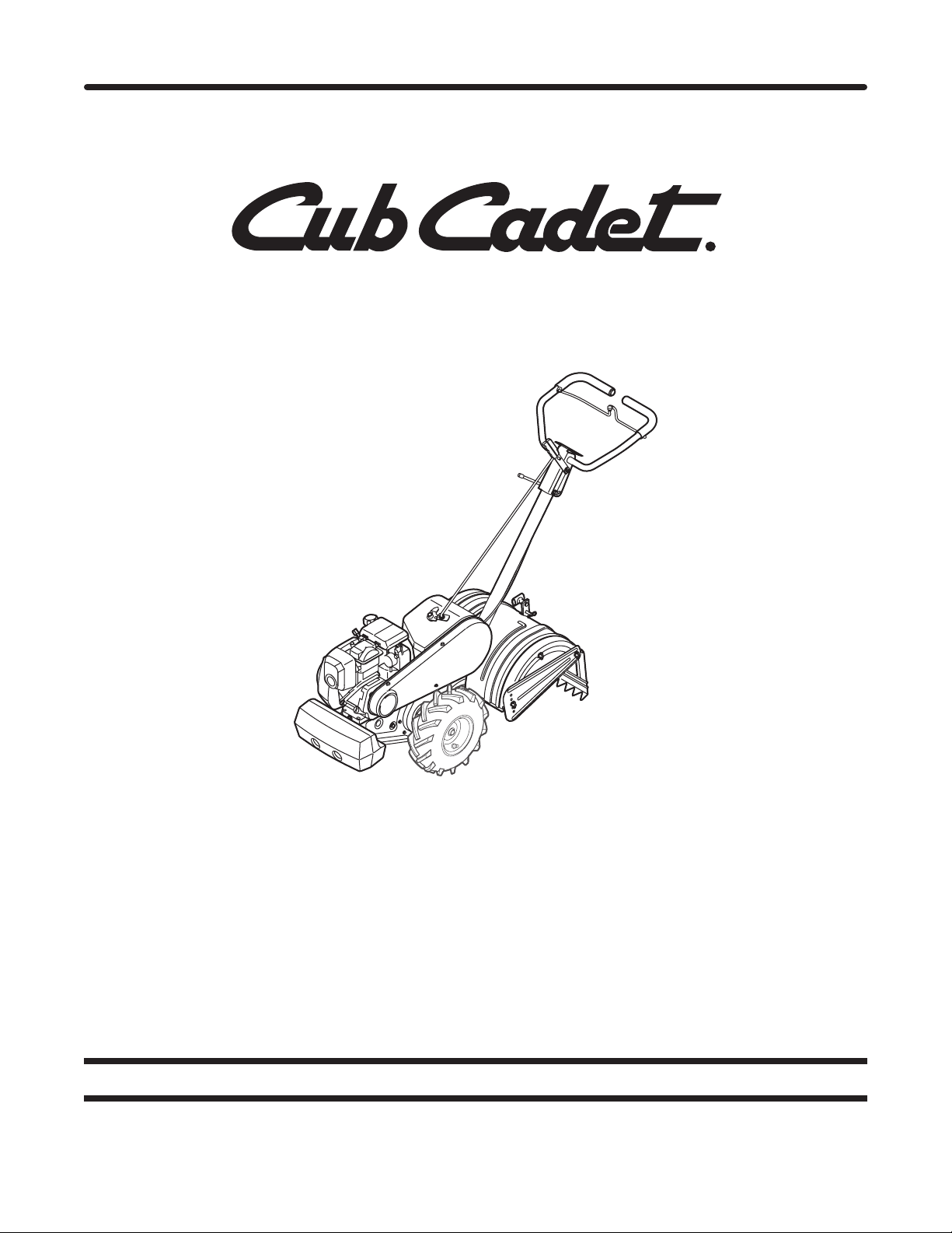
Rear Tine Tiller — Model RT 65
CUB CADET LLC, P.O. BOX 361131 CLEVELAND, OHIO 44136-0019
Form No. 769-05453
(January 20, 2010)
Page 2
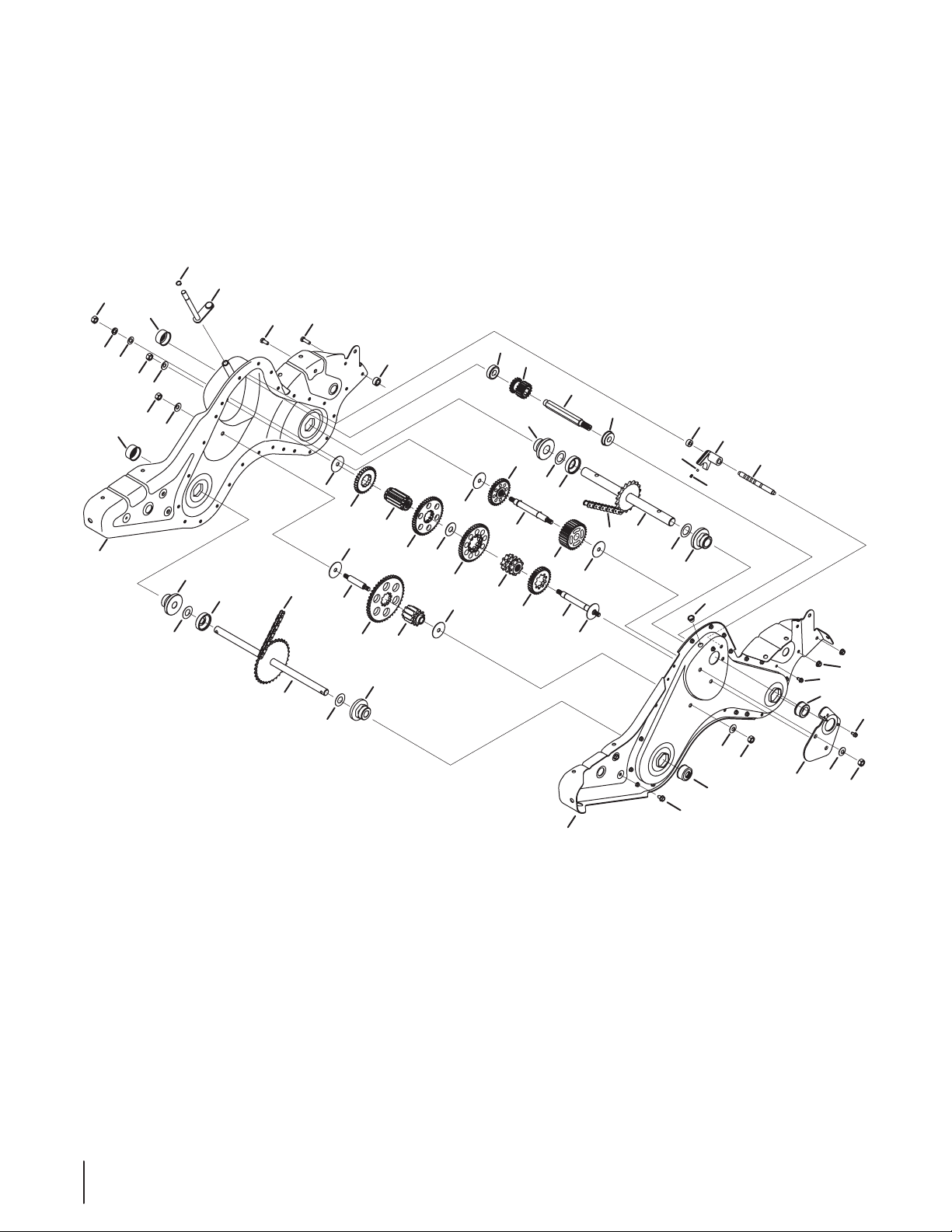
RT 65 Gear Case Assembly
20
16
28
3
11
14
10
34
35
29
16
16
37
37
36
47
41
38
38
45
27
15
38
38
19
48
52
21
49
32
1
33
46
31
37
29
13
16
42
30
37
12
17
28
12
16
46
5
33
51
2
6
7
23
44
40
50
38
24
9
38
25
39
18
43
26
8
47
4
36
22
2
Page 3
RT 65 Gear Case Assembly
Ref.
Part Number Description
1. 611 - 0 0 21 Shaft Assembly, Tine, 18T
2. 611 - 01 28 Shaft Assembly, Jack
3. 611 - 0 12 9 Shaft Assembly, Shift Input
4. 611 - 0 4 0 74 A Shaft Assembly, Wheel, 33T
5. 617 -0 0 58 Gear Assembly, 30T Reverse Idler
6. 617- 0 05 9 Gear Assembly, 30T Tine Idler
7. 617- 0 0 60 Sprocket Assembly, 9T Tine Input
8. 617-00 61 Sprocket Assembly, 10T Whl Input
9. 6 17- 00 62 Gear Assembly, 11T
10. 686-0108A-0637 RH Chain Case Housing Assembly
11. 710-0376 Hex Head Screw, 5/16-18 x 1.00
12 . 710- 0599 Screw, 1/4-20 x 0.500
13. 710-0 604 A Screw, :5/16-18 x 0.625
14. 710 -3008 Hex Head Screw, 5/16-18 x .75
15. 7 11- 13 4 9 Input Shaft, .75
16. 712 -0 378 Nut, Hex, 7/16-20
17. 712-3004A Nut, Flangelock, 5/16-18
18. 913 -0 367 Endless Chain, #420 x 50 Links
19. 913 - 04 84 Endless Chain, #50 x 54 Links
20. 716-0865 Snap Ring, .500
21. 717 -0 85 3A Clutch Collar
22. 717- 158 2 Gear Spur, 44T
23. 717- 158 3 Gear Spur, 30T
24. 7 17-15 84 Gear Spur, 30T
25. 717 -158 5 Gear Spur, 44T
26. 717 -158 7 Gear Spur, 44T
27. 717 -159 4 Gear Spur, 16T
Ref.
Part Number Description
28. 921- 0378 Shaft Seal, 1.0
29. 721- 0379 Shaft Seal, .75
30. 786-0238 Positioner Gear Bracket
31. 726-0277 Tapered Cap Plug
32. 932- 0496 Compression Spring, .230 OD
33. 93 6- 0163 Washer, Flat, 1.03 x 1.62 x .03
34. 93 6- 0 171 Washer, Lock, 7/16
35. 936 -0226 Washer, Flat,.474 x .879 x .064
36. 936 -0351 Washer, Flat, .760 ID x 1.50 OD
37. 736-0407 Washer, Bell,.45 x 1.00 x .062
38. 736 -0518 Washer, Thrust, .445 x 1.92 x .060
39. 736-3088 Washer, Flat,1.595 x .635 x .062
40. 686-04129-0637 LH Chain Case Housing
41. 950-0671 Spacer, .75 x 2.0 x .50
42. 738-0645 Shaft Detent, .5 DIA
43. 738- 0648 Shaft, Jack, .625 x 2.385
44. 73 8-10 13 Shaft, Jack, .6250 x 5.0050
45. 9 41-0 60 0 Ball Bearing, 17 x 40 x 12:6203
46. 941- 04 20 Flange Bearing, 1.0 x 2.5 x 1.38
47. 741- 04 21 Flange Bearing, .75 x 2.5 x 1.38
48. 941- 05 63 Ball Bearing, 17 x 40 x 12:6203
49. 741-0862 Ball, Detent, .250
50. 750-0258 Spacer, .315 x .750 x .375 LG
51. 950-0570 Spacer, 1.0 ID x 2.0 OD x.5 LG
52. 750 -06 64 Spacer, .505 ID x .88 OD x .440
— 98 6- 04 074 A Gear Case Assembly Complete
3
Page 4
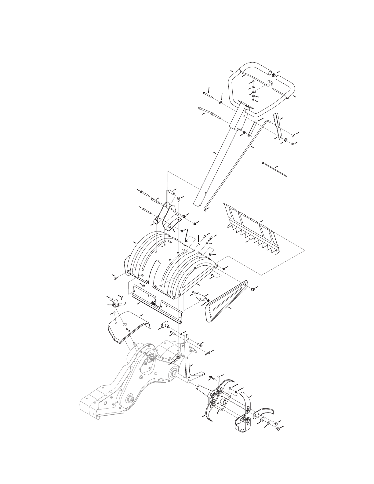
RT 65 Handle & Tine Assembly
13
1
38
2
3
32
46
34
54
30
42
29
45
20
8
17
28
16
14
30
41
33
35
34
40
37
31
47
18
5
11
25
34
36
31
38
39
34
34
10
6
19
22
4
20
15
23
9
21
43
44
12
7
35
48
65
26
52
49
51
50
55
56
64
59
57
58
61
54
62
60
53
24
27
63
4
Page 5
RT 65 Handle & Tine Assembly
Ref.
Part Number Description
1. 747-1152 Shaft Rod
2. 64 9-00 34- 4021 Lower Handle Tube Assembly
3. 6 49 -0 041- 4021 Upper Handle Assembly
4. 710 -09 46 Screw, 1/4-20 x 0.625
5. 710 -3005 Hex Head Screw, 3/8-16:1.25
6. 710 -3056 Hex Head Screw, 5/16-18 x 3.25
7. 911 - 0 41 5 Clevis Pin, .375 X 1.75
8. 712 -0 324 Hexlock Nut, 1/4-20
9. 7 12- 037 9 Flangelock Nut, 3/8-24
10. 912 -0 42 9 Hexlock Nut, 5/16-18
11. 714 -0147 Cotter Pin, .125 X 1.75 INTERNAL
12 . 72 0- 0210A Small Tee Knob
13. 720-0278A Foam Grip, .970 x 11.0
14. 7 20 -0 313 Grip, .1875 x 1.00
15. 726- 0273 Battery Clamp, 5/16
16. 7 26 - 0317 Cable Tie, 8.5 LG
17. 735- 0246A End Plug
18. 9 36 - 011 7 Washer, Flat, .385 x .620 x .033
19. 736-0242 Washer, Bell, .340 x .872 x .060
20. 736-3090 Washer, Flat, .260 x .720 x .060
21. 938- 0958 Spacer, Shoulder, .50 x .190 x .360
22. 747-1219 -0 637 Clutch Bail
23. 78 4- 0190 Handle Adjustment Crank
24. 7 84 -019 1 Hex Nut Retainer Bracket
25. 786-0120-0637 Tiller Depth Control
26. 786-0181-4021 Shaft Rod Lever
27. 73 5- 0127 Washer, Rubber, .33 ID x .125
28. 914 -010 4 Cotter Pin, .072 x 1.12 LG
29. 686-0044B-4021 End Cover Assembly
30. 7 10 - 0176 Hex Head Screw, 5/16-18 x 2.75
31. 710 -3008 Hex Head Screw, 5/16-18 x .75
32. 710 -302 2 Hex Head Screw, 3/8-16 x 2.75
33. 710 -0 4482 Hex Head Flange, 3/8-16 x .875
Ref.
Part Number Description
34. 7 12- 04 06 3 Flangelock Nut, 5/16-18
35. 7 12- 04 06 5 Flangelock Nut, 3/8-16
36. 7 12- 04 21 Wing Nut, 5/16-18 W/ Bell Washer
37. 926 -0106 Speed Nut Cap, 1/4 ROD
38. 736-0204 Washer, Flat, .344 x .62 x .033
39. 938-0849 Screw, Hex, 5/16-18 x .75
40. 747- 0432 Tiller Flap Rod
41. 750-0885A Spacer, .322 x .625 x 2.00
42. 78 6-0090A- 4021 Side Shield
43. 786-0113A-4021 Rear Tine Shield
44. 786-0176-4021 RH Handle Mount Bracket
45. 786-0177-4021 LH Handle Mount Bracket
46. 786 -0178A- 4021 Tine Shield
47. 786-0179-0637 FRT Tine Shield Bracket
48. 786-0180-0637 FRT Tine Shield Spacer Bracket
49. 6 86- 0109A Shift Crank Assembly
50. 7 10 -1017 Screw, ⁄-14 x .625
51. 915 - 0120 Spiral Pin, ⁄ x 1.0
52. 784- 0208D-4021 Shift Cover
53. 9 11- 0 415 Clevis Pin
54. 7 12-3 05 4 Hex Nut, ⁄-24
55. 742- 0305A- 0637 13” Articulating Tine
56. 938-0689 Shoulder Bolt
57. 936-0253 Bell Washer, .515” ID x 1.14” OD
58. 938-0688 Shoulder Bolt
59. 784-0160-0637 Tine Adapter Assembly, 18”
60. 714-04043 Internal Cotter Pin
61. 93 6- 0169 Lock Washer
62. 784-0161-0637 Tine Adapter Plate
63. 731- 0755 6 Cap
64. 936 -0208 Washer, Flat, .51 x 1.5 x .07
65. 710 -13 07 Stud, 5/16-18 x .75
5
Page 6
27
129
26
4
35
38
36
37
34
32
33
33
29
32
3
30
41
40
39
31
24
13
15
7
21
20
5
16
22
23
11
2
13
8
25
28
10
17
1
18
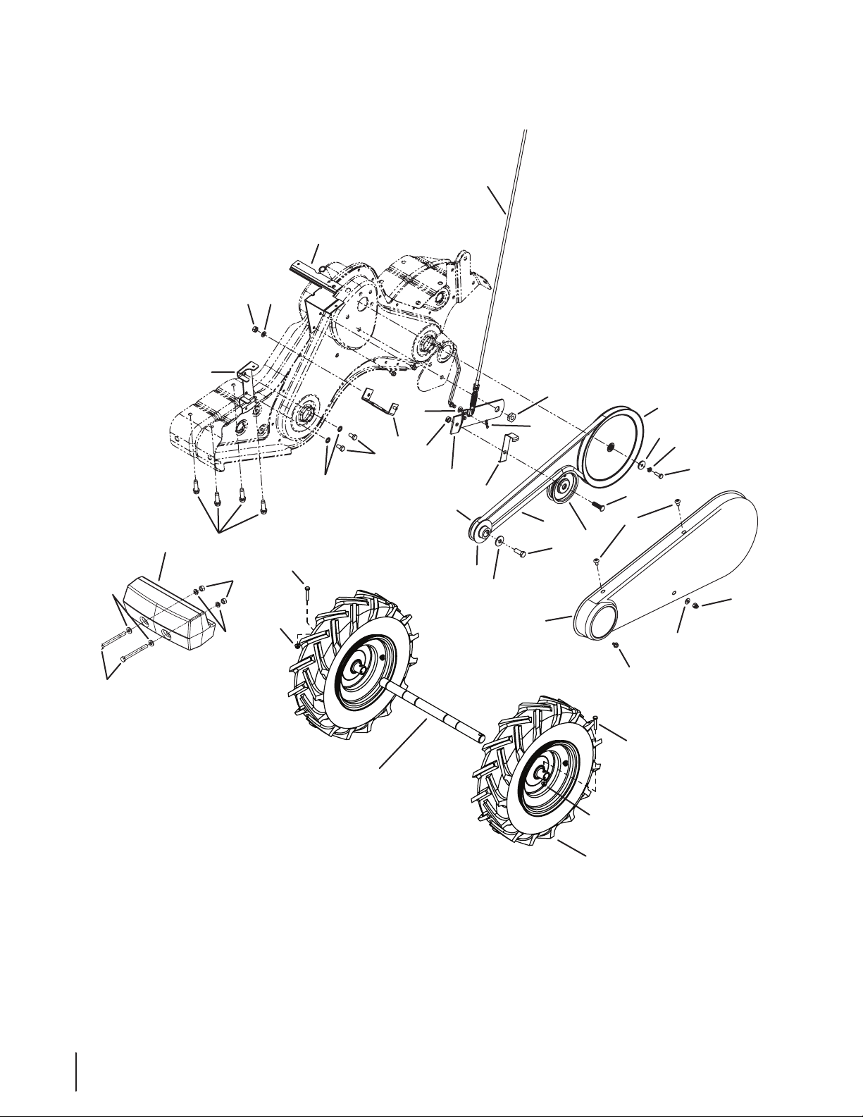
Wheel shaft shown
for reference only.
RT 65 Drive System
6
Page 7
RT 65 Drive System
Ref.
Part Number Description
1. 6 8 6 - 0111 - 0 6 37 Belt Cover Bracket Assembly
2. 710-0237 Hex Bolt, ⁄-24 x .62”
3. 71 0- 0 412 Hex Bolt, ⁄-28 x .75”
4. 710 -052 0 Hex Washer Screw, ⁄-16 x 1.50”
5. 710 -1039 Hex Bolt, ⁄-24 x 1.0
6. 710 -059 9 Hex Washer Screw
7. 710-3005 Hex Cap Screw, ⁄-16 x 1.25
8. 712-0266A Lock Jam Nut, ⁄-1 6
9. 912-0267 Hex Nut, ⁄-1 8
10. 914 -010 4 Internal Cotter Pin
11. 936 -010 4 Hairpin Clip
12 . 9 3 6 - 011 9 Lock Washer, ⁄”
13. 9 36 - 0176 Flat Washer, .25 ID x .93 OD
14. 936 -0271 Spring Washer, .317 ID x .625 OD
15. 936- 0329 Lock Washer, ⁄” ID
16. 936-0452 Bell Washer, .396 ID x 1.14 OD
17. 938-0876 Shoulder Nut, ⁄-20
18. 74 6 - 1117 Clutch Cable
19. 747 -1159 Idler Pulley Rod
20. 954-0434 V-Belt
21. 756-0405 Flat Idler w/ Flange, 3.75 OD
Ref.
Part Number Description
22. 756- 0971 Outer Engine Pulley Half
23. 756-0972 Inner Engine Pulley Half
24. 7 5 6 -11 62 Input Pulley
25. 786-0064A Idler Bracket
26. 786-0185A-0637 Belt Keeper Bracket
27. 786-0187-0637 Shift Cover Bracket
28. 786-0193-0637 Idler Belt Keeper
29. 934 -0 4231 Wheel Assembly, 16.0 x 4.6 x 8
30. 936-3020 Flat Washer, .271 ID x .630 OD
31. 784-0158A-4021 Belt Cover
32. 710-0606 Hex Head Screw, ⁄-20
33. 7 12- 04 06 4 Flange Lock Nut, ⁄-20
34. 710 -0382 Hex Bolt, ⁄-13 x 5.0
35. 9 12- 020 6 Hex Nut, ⁄-13
36. 723-0381 Counterweight, 40 lbs.
37. 936-0326 Flat Washer
38. 936 -0 921 Lock Washer, ⁄
39. 710 -0 653 Hex Screw, ⁄-20 x .375
40. 7 10 -1017 Screw, ⁄-14 x .625
41. 7 12- 039 2 Lock Nut
7
Page 8
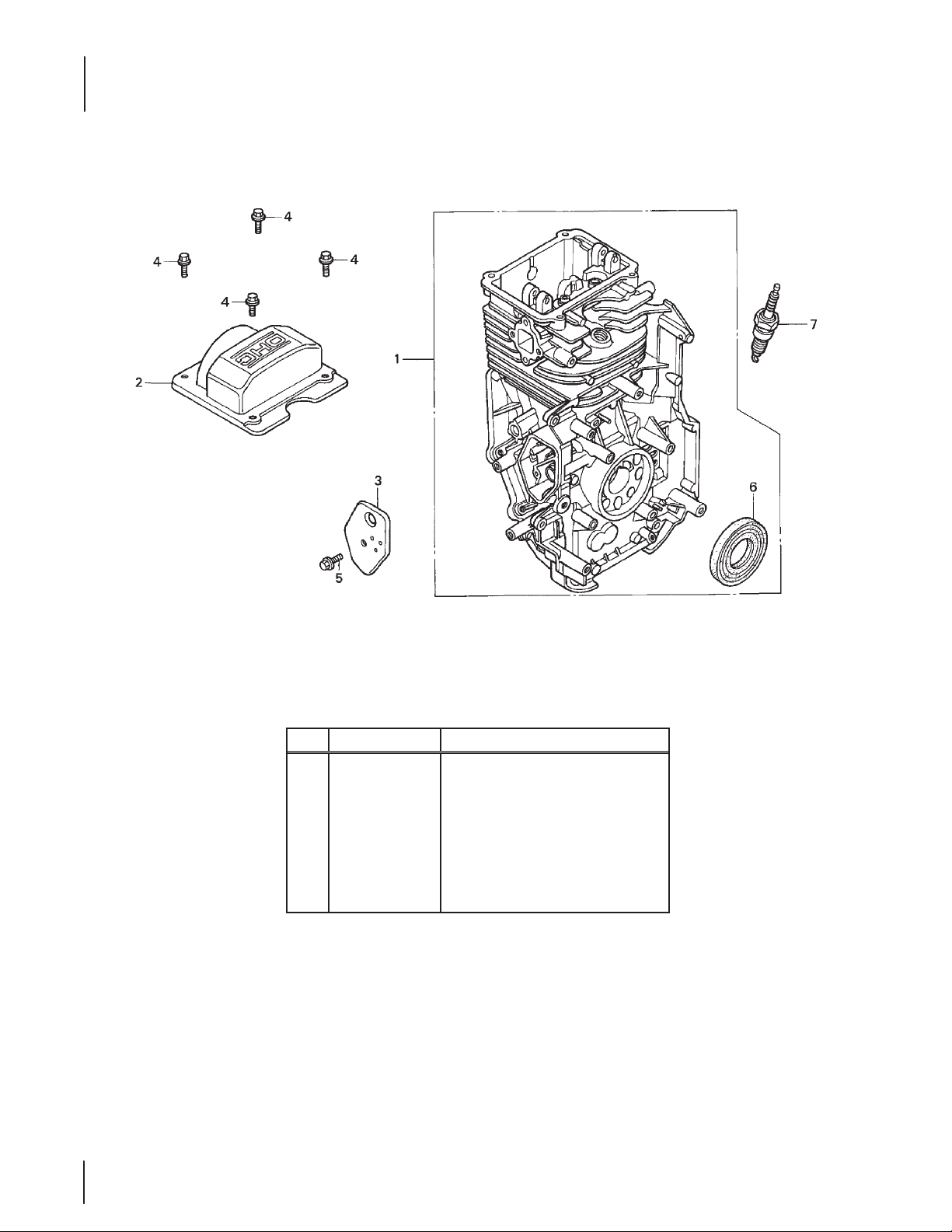
RT 65 Honda GCV190LA Cylinder
CYLINDER
Ref. Part Number Description
12000-Z0Y-415
1.
2. 12310-Z0J-000 Head Cover
3. 12355-ZL8-000 Breather Cover , Valve Assembly
4. 90013-883-000 Flange Bolt, 6 X 12
5. 90014-952-000 Flange Bolt, 6 X 14
6. 91201-Z0Y-003 Oil Seal, 25.4 X 62 X 6
7. 98079-56846 Spark Plug (BPR6ES NGK)
8
8
Cylinder Assembly
Page 9

RT 65 Honda GCV190LA Crankcase Cover
OIL PAN
Ref. Part Number Description
1. 113 0 0 - Z0 Y- Y 06 Crankcase Cover Assembly
3. 15650-Z0L-000 Oil Filler Cap Assembly
4. 15625-ZE6-000 Oil Filler Cap Gasket
5. 16510 -ZM0-010 Governor Assembly
6. 16531-ZE1-00 0 Governor Slider
7. 16541-ZM0-000 Governor Arm Shaft
8. 90121-952-000 Flange Bolt, 6 x 25
9. 90131-883-000 Drain Plug Bolt
10. 90451-ZE1- 000 Thrust Washer, 6mm
11. 90602-ZE1-000 Governor Holder Clip
13. 9 1202 -ZL 8 -0 03 Oil Seal, 28 x 41.25 x 6
14. 9 4101- 06 80 0 Plain Washer, 6mm
15. 94109-12000 Drain Plug Washer, 12mm
16. 94251-08000 Lock Pin, 8mm
17. 943 01-08200 Dowel Pin, 8 x 20
9
9
Page 10

CRANKSHAFT
1
2
RT 65 Honda GCV190LA Crankshaft
10
10
Ref. Part Number Description
1. 13310 -Z0Y- 610 Crankshaft (M-Type)
2. 90402-ZL8-000 Thrust Washer
Page 11

RT 65 Honda GCV190LA Piston
Ref. Part Number Description
1. 13010 -Z0Y- 014 Piston Ring Set (Teikoku)
2. 13101-Z0Y-010 Piston
3. 1 3111 -Z 0 Y- 0 0 0 Piston Pin
4. 13200-Z0Y-000 Connecting Rod Assemblt
5. 90001-ZE1-000 Connecting Rod Bolt
6. 90551-ZE0-000 Piston Pin Clip, 13mm
11
11
Page 12

RT 65 Honda GCV190LA Camshaft
CAMSHAFT
12
12
Ref. Part Number Description
1. 12 20 9- ZM 0- 0 03 Valve Stem Seal
2. 14320-Z0Y-000 Cam Pulley
3. 14324-ZL8-00 0 Cam Pulley Shaft
4. 14 40 0- Z0J -014 Timing Belt, 84HU& G-200
5. 14431-Z0J-000 Internal Valve Rocker Arm
6. 14441-Z0J-000 External Valve Rocker Arm
7. 14461-ZL8-000 Rocker Arm Shaft
8. 14711-Z0J-000 Internal Valve
— 14711-Z0J-000 Internal Valve
9. 14721-ZL8-000 External Valve
10. 14751-ZL8-000 Valve Spring
11. 14777-Z0J-000 Internal Valve Spring Retainer
12 . 90012-333-000 Tappet Adjustable Screw
13. 90206-001-000 Tappett Adjustble Nut
14. 913 01-Z M0 -V 31 O-Ring, 6.8 x 1.9
Page 13

RT 65 Honda GCV190LA Recoil Starter
RECOIL STARTER
Ref. Part Number Description
28400-Z0Y-V202A
1.
28400-Z1A-013ZB
—
2. 28461-ZL8-003 Recoil Starter Knob
3. 28462-ZL8-003 Recoil Starter Rope, #3.5 x 52”
Recoil Starter Assembly (Black)
Recoil Starter Assembly (Power Red)
13
13
Page 14

FAN COVER
RT 65 Honda GCV190LA Fan Cover
14
14
Ref. Part Number Description
1.
—
2. 90043-ZL8-000 Stud Bolt
3. 19619 -ZL8 -3 00 Flange Nut, 6mm
19610 -Z0L-8 51Z A
19610-Z0L-850ZE
Fan Cover (Black)
Fan Cover (Power Red)
Page 15

RT 65 Honda GCV190LA Carburetor
CARBURETOR
Ref. Part Number Description
1. 16 010 -883- 015 Gasket Set
2. 1 60 13- ZL1 -0 0 3 Float Set
3. 16015-887-782 Float Chamber Set
4. 16 016-ZG0 -W0 0 Screw Set
5. 16 0 24 - Z E1 - 811 Drain Screw Set
6. 16028-ZE0-005 Screw Set B
7. 16 029-ZG 0-9 01 Screw Set
8. 1610 0-Z0 Y-821 Carburetor Assembly, BB65C A
9. 1615 5-Z M0 - 013 Float Valve
10. 1616 6-Z1A -003 Main Nozzle
11. 16211-ZL8-000 Carburetor Insulator
Ref. Part Number Description
12 . 16212-ZL8-000 Insulator Gasket
13. 16221-887-800 Carburetor Gasket
14. 16228-ZL8-000 Carburetor Gasket (Choke Side)
15. 19650-ZM0-000 Air Guide
93500-05006-1H
16.
17. 95002-02080 Tube Clip, B8
95003-07008-60M
18.
19. 9 9101 -124 -0 65 0 Main Jet, #70
— 9 9101-12 4- 0 65 0 Main Jet, #65
— 9 9101-12 4- 0 68 0 Main Jet, #68
Pan Screw, 5 x 6
Vinyl Bulk Hose (4X7X8000, 4X7X150)
15
15
Page 16

RT 65 Honda GCV190LA Air Filter
AIR CLEANER
16
16
Ref. Part Number Description
1. 15721-ZM0-000 Breather Tube
2. 17211-ZL8-023 Air Cleaner Element
3. 17220-ZM0 -020 Air Cleaner Housing
4. 17228-ZM0-000 Air Cleaner Gasket
5. 172 31- Z0 L- 04 0 Air Cleaner Cover
6. 90003-ZM0-000 Flange Bolt, 6 x 112
Page 17

RT 65 Honda GCV190LA Muffler
MUFFLER
Ref. Part Number Description
1. 18310-Z0J-000 Muer
2. 18321-Z0L-000 Muer Protector
4. 18381-ZL8-305 Muer Gasket
6. 19664-ZL8-000 Muer Shroud
7. 90004-ZL8-000 Flange Bolt, 6 x 79
8. 90013-883-000 Flange Bolt, 6 x 12
9. 90055-ZE1-000 Tapping Screw, 4 x 6
10. 18350-ZL8-000 Spark Arrester
11. 18356-ZL8-000 Arrester Number Plate
12 . 90055-ZE1-000 Tapping Screw, 4 x 6
13. 06180-Z0J-000 Spark Arrester Kit
17
17
Page 18

RT 65 Honda GCV190LA Fuel System
Ref. Part Number Description
1. 16854-ZH8-000 Supporter Rubber, 107mm
2. 16950-ZM0-003 Fuel Pump Assembly
3. 16 952-Z A8- 800 Fuel Strainer
4. 17511-Z0 L- 010 Fuel Tank
5. 17514-Z0L-000 Fuel Filler Neck Seal
6. 17516-Z0L-000 Tank Mounting Clip
7. 17532-Z0L-000 Tank Mounting Rubber, A
8. 17533-Z0L-000 Tank Mounting Rubber, B
9. 17534-Z0L-00 0 Tank Mounting Nut
10. 17 62 0- Z0 J- 8 00 Fuel Cap Assembly
11. 17636-Z0L-000 Fuel Level Gauge
18
18
Ref. Part Number Description
12 . 177 01- Z0 L- 810 Fuel Tank Tube
13. 17702-ZM0-800 Fuel Tube
33609-GK4-620
14.
15. 93891-05010-08 Screw-Washer, 5 x 10
16. 95002-02080 Tube Clip, B8
17. 95002-02100 Tube Clip, B10
18. 95002-7000 Tube Clip, C11
19. 95002-40800-08 Tube Clamp, D8
20. 95002-41000-08 Tube Clamp, D10
21. 95002-41200-08 Tube Clamp, D12
Collar
Page 19

RT 65 Honda GCV190LA Flywheel
FLYWHEEL
Ref. Part Number Description
1. 13331-357-000 Special Woodru Key, 25 x 18
2. 30500-Z0J-003 Ignition Coil Assembly
3. 31105-Z0Y-010 Flywheel
5. 32195-ZM0 -800 Stop Switch Wire
6. 51125-Z0L-003 Stop Switch Wire Holder
8. 90022-888-010 Flange Bolt, 6 x 20
9. 90213-S3Y-000 Flange Nut, 14mm
19
19
Page 20

RT 65 Honda GCV190LA Controls
CONTROL (1)
Ref. Part Number Description
1. 16500-ZL8-000 Control Assembly
2. 16551-Z M0-010 Governor Arm
3. 16555-Z0L-800 Governor Rod
4. 16561-Z M0 -V3 0 Governor Spring
5. 16562-ZM0- 000 Throttle Return Spring
6. 166 12-Z M0 -V 30 Control Lever
7. 16574-ZE1-000 Lever Spring
8. 16 575-Z E2-W 00 Control Lever Washer
9. 16578-ZE1-000 Control Lever Spacer
10. 16580 -Z0L-810 Control Base
11. 16 674 -ZM 0 -V3 0 Choke Control Rod
20
20
Ref. Part Number Description
12 . 16613-893-000 Choke Rod Grommet
13. 19612-ZL8-000 Side Plate
14. 3512 0 -ZL 8 -0 03 Engine Stop Switch Assembly
15. 90013-883-000 Flange Bolt, 6 x 12
16. 90014-952-000 Flange Bolt, 6 x 14
17. 90015 -ZE5-010 Governor Arm Bolt
18. 90114-SA0-000 Self-lock Nut, 6mm
19. 93892-04012-00 Screw-Washer, 4 x 12
20. 94050-06000 Flange Nut, 6mm
21. 94103-04000 Plain Washer, 4mm
Page 21

Notes
21
Page 22

22 no t e s
Page 23

23 no t e s
Page 24

U
I
N
N
E
G
F
A
C
T
O
R
To order replacement parts, call a Customer Support Representative at (800) 965-4CUB.
Locate your nearest Cub Cadet dealer at (877) 282-8684
or visit www.cubcadet.com to find the nearest Cub Cadet dealer in your area.
E
S
T
R
A
P
Y
CUB CADET LLC, P.O. BOX 361131 CLEVELAND, OHIO 44136-0019
 Loading...