

Page 1
Illustrated Parts Manual
Printed In USA
Front Tine & Rear Tine Tillers
Model FT24, RT 45 & RT 65
CUB CADET LLC, P.O. BOX 361131 CLEVELAND, OHIO 44136-0019
Form No. 769-07278
(August 31, 2011)
Page 2
To The Owner
Thank You
Thank you for purchasing a Cub Cadet Tiller. It was carefully
engineered to provide excellent performance when properly
operated and maintained.
All information in this manual is relative to the most recent
product information available at the time of printing. Please be
aware that this Illustrated Part’s Manual may cover a range of
product specifications for various models.
Table of Contents
Briggs Engine 12T102-0937-F8 ............................. 62
Engine Honda GC190LA ....................................... 22
Engine Model-170-T0B .......................................... 36
Engine Model-170-TU ............................................ 72
Engine Model-170-V0B .......................................... 44
Components listed and/or illustrated in this manual may not be
applicable to all models. We reserve the right to change product
specifications, designs and equipment without notice and
without incurring obligation.
Throughout this manual, all references to right (RH) and left (LH)
are observed from the operating position.
Engine Model-170-VU ........................................... 82
Engine Model-270-V0 ............................................ 52
Model Series 300 ..................................................... 4
Model Series 400 ....................................................10
Model Series 450 ....................................................16
Record Product Information
To ease in ordering replacement parts, please locate the model
plate on the equipment and record the information in the
provided area to the right. You can locate the model plate by
looking beneath the seat.
Model NuMber
Serial NuMber
Painted Parts
When ordering painted service parts, a four digit color suffix must be added to the part number (e.g. 783-XXXXX-0637).
Please refer to the table below for current color codes:
0637 Black
4021 Yellow (Cub Cadet)
0499 Beige (Cub Cadet)
0685 Blue (Cub Cadet)
0691 Black Jack (Cub Cadet Commercial)
2
Page 3

Page Left Blank Intentionally
33
Page 4
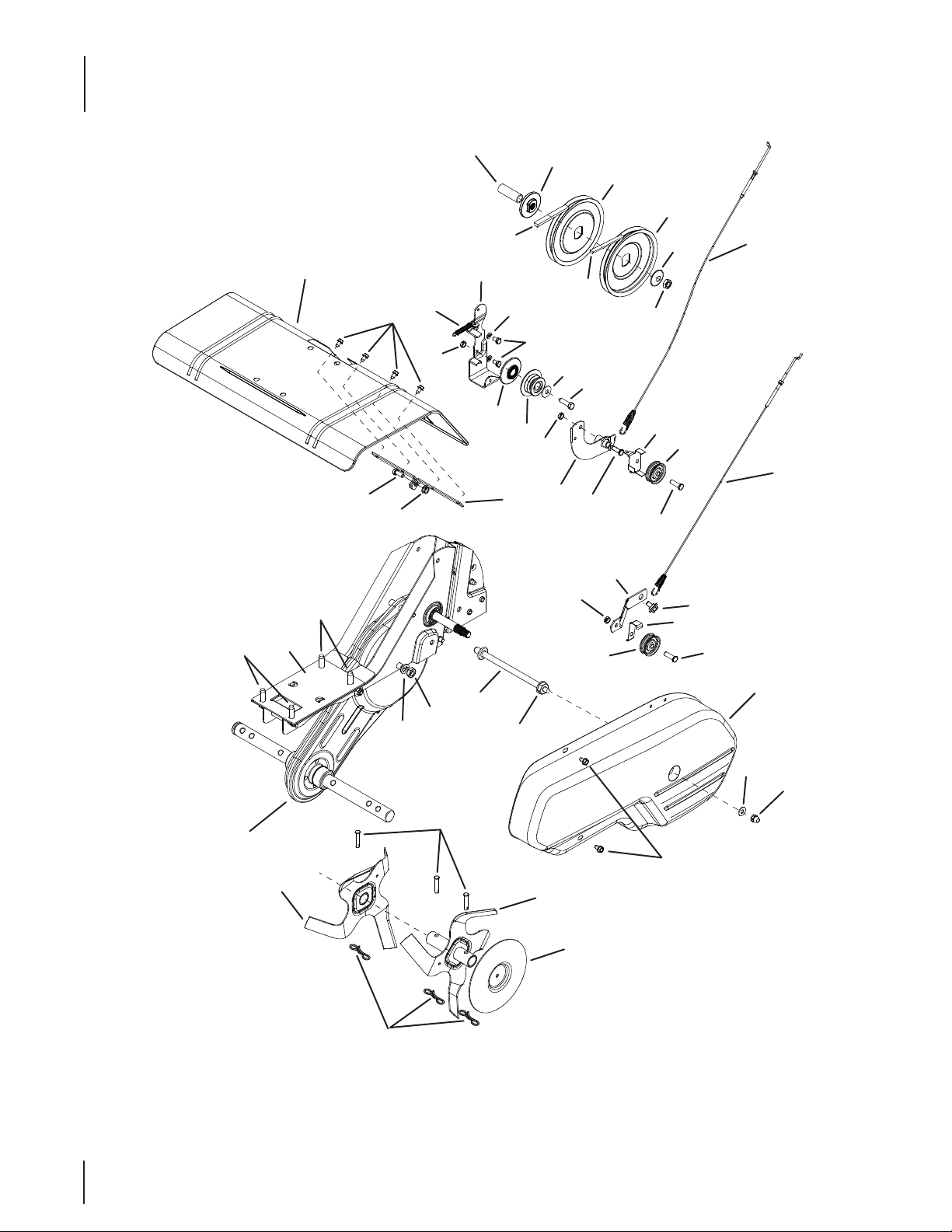
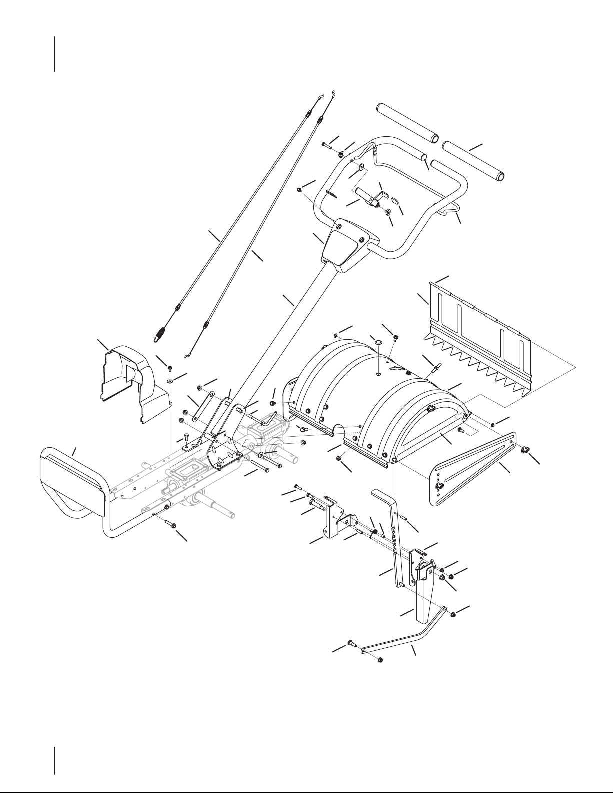
Model Series 300
10
46
34
4
6
9
11
7
13
29
36
32
30
3
31
26
12
14
15
20
24
25
45
21
22
2
8
16
47
17
19
27
28
10
6
1
2
5
18
33
35
40
35
28
44
37
28
38
39
21
41
25
23
42
43
44
Page 5
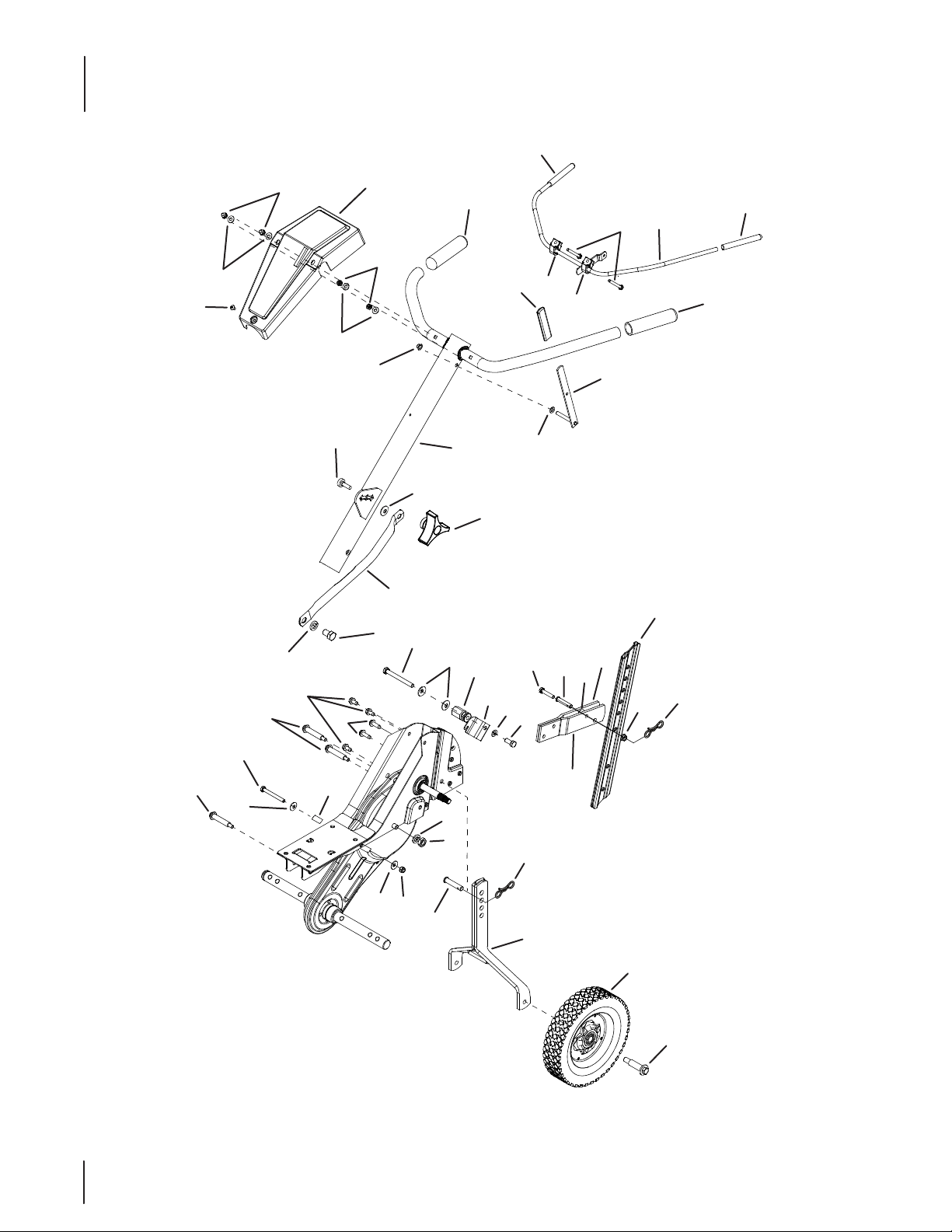
Model Series 300
Ref. Part Number Description
1. 912-0442 Acorn Lock Nut, ⁄-20
2. 936-3020 Flat Washer, .271” x.630”
3. 720-0270A† Reverse Handle Grip
4. 731-160 0 Handle Cover w/o throttle (390)
— 731- 06253A Handle Cover (340)
5. 710 -0779A Truss Machine Screw, #10 x ⁄”
6. 720- 0274 Handle Grip
7. 712-3006 Hex Nut, ⁄-20 (390)
— 912-0298 Jam Nut, 1/4-20 (340)
8. 726-0135† Cap Speed Nut
9. 686-0083 Clutch Handle Assembly
10. 720-0269 Clutch Grip
11. 710-0641 Hex Bolt, ⁄-20 x 2.25”
12. 931-16 45B Clutch Handle Holder
13. 936 -0140 Flat Washer, .385” x .62”
14. 686 -0014C† Reverse Handle Assembly
15. 936- 0264† Flat Washer, .344” x .62”
16. 649-04040 Handle Assembly Complete
17. 749-1401A Handle Brace
18. 936- 0921 Lock Washer, ⁄
19. 710-3194 Hex Bolt, ⁄-20
20. 786-0005 Depth Bar
21. 714-04043 Cotter Pin, Bow Tie
22. 712-040 63 Hex Flange L-Nut, ⁄-18
23. 786-0003 Tail Piece Bracket, Left
Ref. Part Number Description
24. 786-0004 Tail Piece Bracket, Right
25. 911 - 0415 Clevis Pin
26. 710-0805 Hex Bolt, ⁄-18 x 1.5”
27. 710 -0189 Hex Bolt, ⁄-18 x 3”
28. 736-0242 Bell Washer, .340” x .872”
29. 7 11-1036 A Hex Nut
30. 93 6-0119 L-Washer, ⁄”
31. 710 -3008 Hex Bolt, ⁄-18
32. 786-0129 Cable Guide Bracket
33. 710 -06 04A Hex Washer Screw, ⁄-18 x .62”
34. 710- 0602 Hex Washer TT-Tap Screw
35. 738-0934 Shoulder Bolt, ⁄-18
36. 720-0195 Hand Knob
37. 750- 0470 Spacer
38. 936 - 0171 Lock Washer, ⁄
39. 912- 0240 Jam Nut, ⁄-20
40. 710 -0176 Hex Bolt, ⁄-18 x 2.75”
41. 912- 042 9 Nylon Hex Nut, ⁄-18
42. 686-0081A Wheel Hanger Bracket Assembly
43. 734-04623 Wheel, 8 x 1.75
44. 738-0929 Shoulder Screw, .496 x 1.445
45. 750-0890 Spacer
46. 710 -1236 Carriage Bolt, ⁄-18 x 1
47. 736- 0242 Bell Washer, .34”
† If Equipped
55
Page 6
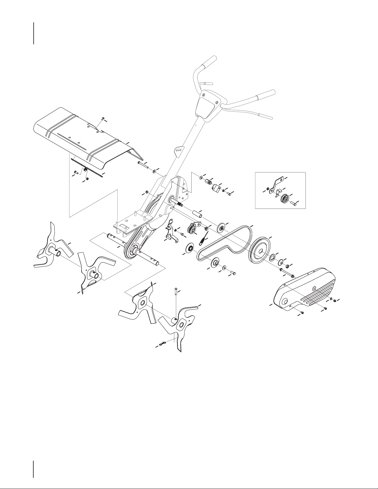
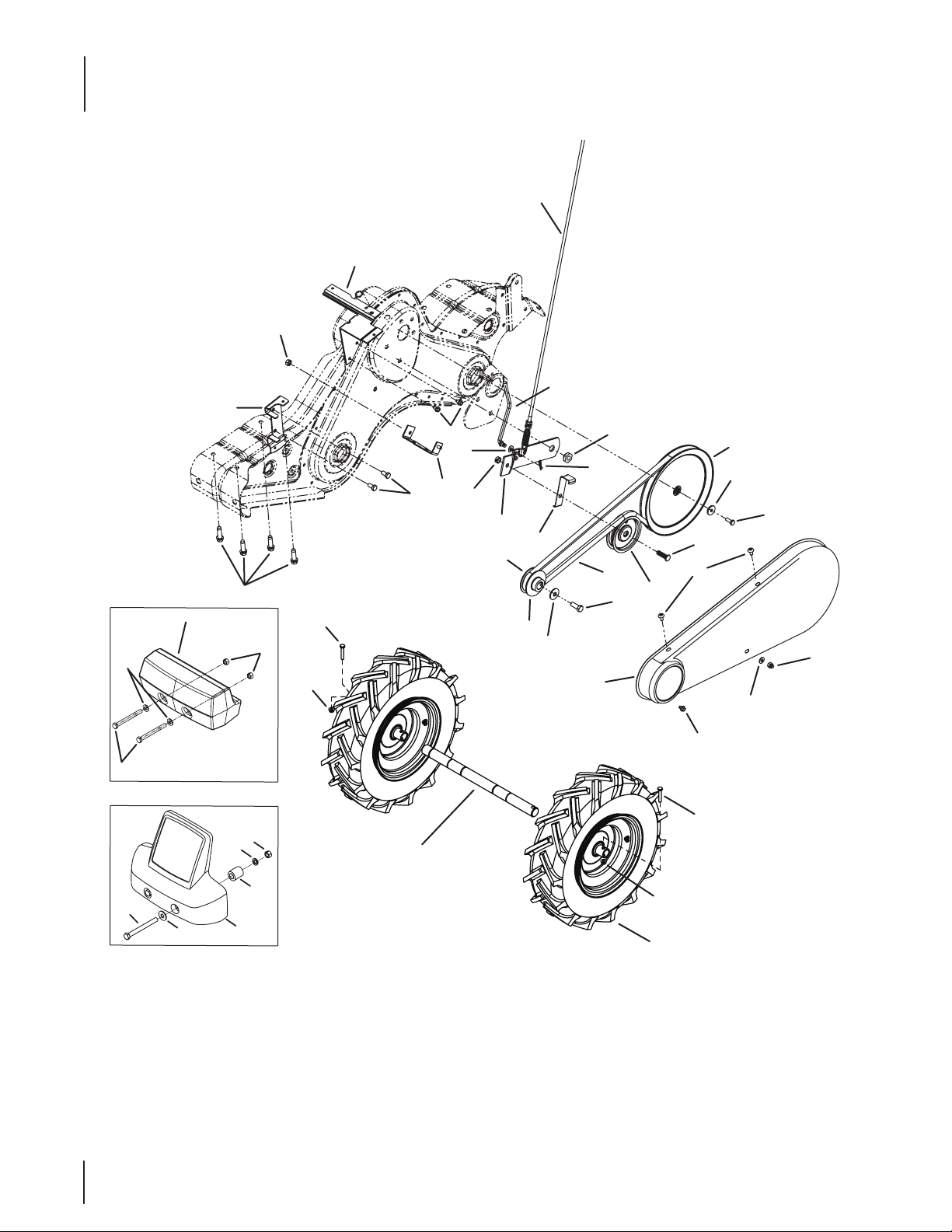
Model Series 390
23
42
24
22
22
25
21
37
38
12
27
3
10
13
5
37
41
40
28
29
30
31
32
39
4
46
10
35
33
10
43
34
44
26
36
7
20
6
9
45
8
7
6
11
2
1
14
19
16
66
17
3
18
15
Page 7
Model Series 390
Ref. Part Number Description
1. 712-0392 Hex L-Stop Nut, ⁄-28
2. 936-3020 Flat Washer, 266” x .625”
3. 710 -0599 Hex Washer TT-Tap Screw, ⁄-20 x .5”
4. 711- 092 0 Belt Cover Bolt
5. 712- 04063 Hex Flange Top L-Nut, ⁄-18
6. 710-30 05 Hex Head Screw, ⁄-16 x 1.25”
7. 756-0313 Flat Idler Pulley, 2.12”
8. 786-0149 Idler Belt Keeper
9. 786- 0144 Idler Bracket
10. 712-0266A Hex Center Jam Nut, ⁄-16
11. 786-0057 Belt Cover w/ rev.
12. 786- 0043A Tine Shield
13. 710-3008 Hex Head Cap Screw, ⁄-18 x .75”
14. 986-0091 Chain Case Assembly Complete
15. 686 -0106 Outer Disc Plate Assembly
16. 714-04043 Cotter Pin, Bow Tie
17. 911- 0415 Clevis Pin
18. 642-0023 Outer Tine Assembly, LH,
— 642- 0024 Outer Tine Assembly, RH
19. 642-0003 Inner Tine Assembly, Left
— 642-0002 Inner Tine Assembly, Right
20. 94 6-0918 Forward Clutch Cable
21. 946-0953 Reverse Clutch Cable
22. 756-0585 Flat Pulley, 6”
Ref. Part Number Description
23. 950-0892 Spacer, .64” x 2.4”
24. 948-0350 Pulley Mounting Adapter
25. 736 - 0112 Bell Washer, 525” x 1.5”
26. 712-3029 Hex Jam Nut, ⁄-20
27. 732- 0697 Return Spring
28. 786-0040B Reverse Bracket
29. 9 3 6 -0119 Lock Washer, ⁄
30. 710-0237 Hex Bolt, ⁄-24 x .625”
31. 756 -0971 Engine Inner Pulley
32. 756- 0600 Reverse Engine Pulley
33. 936 -0452 Bell Washer, .396” x ⁄”
34. 710-1039 Hex Bolt, ⁄-24 x 1.00”
35. 6 86-0013 Reverse Arm Assembly
36. 786-0041 Reverse Belt Keeper
37. 710 -0502A Hex L-Washer TT-Tap, ⁄-16 x 1.25”
38. 786-0145A Engine Plate
39. 786- 0053 Tine Shield Bracket
40. 936 - 0171 L-Washer, ⁄”
41. 912- 0240 Hex Nut, ⁄-20
42. 954-0428 Forward Drive Belt, ⁄ x 41.9”
43. 954- 0429 Reverse Drive Belt, ⁄ x 45.68”
44. 938-0102 Shoulder Screw, .498 x 1.445
45. 738-0930 Shoulder Screw, .560 x.165
46. 712-3004A Flangelock Nut, 5/16 - 18
77
Page 8
Model Series 340
15
16
18
8
17
20
29
11
34
29
24
41
28
15
19
25
42
43
36
23
33
19
39
13
32
31
22
5
28
4
1
2
40
3
7
21
38
6
35
14
37
30
27
26
9
12
8
8
10
88
Page 9
Model Series 340
Ref. Part Number Description
1. 986- 0091 Chain Case Assembly
2. 642-0002 Inner Tine Assembly, RH
3. 642-0003 Inner Tine Assembly, LH
4. 642-0004 Outer Tine Assembly, RH
5. 642-0005 Outer Tine Assembly, LH
6. 911 - 0415 Clevis Pin, .375 x 1.75
7. 714-04043 Bow Tie Cotter Pin
8. 710-0599 Screw, 1⁄4-20 x 0.500
9. 7 11- 0919 Bolt, Belt Cover
10. 712-0392 Nut, 1/4-28, Lock
11. 712-3004A Nut, 5/16-18, Flange Lock
12. 936-3020 Flat Washer, .271 x .630 x .065
13. 738-0930 Shoulder Screw, .560 x .165 5/16-18
14. 786-0056 Belt Cover
15. 710-3008 Hex Head Screw, 5/16-18 x .75
16. 712-04063 Nut, 5/16-18, Flange Lock
17. 786-0043A Tine Shield
18. 786 -0053 Bracket, Tine Shield
19. 686-0088 Idler Bracket Assembly
20. 710-0189 Hex Head Screw, 5/16-18 x 3.00
21. 710-0237 Hex Head Screw, 5/16-24 x .625
22. 710-1039 Hex Head Screw, 3/8-24 x 1.00
Ref. Part Number Description
23. 710-30 05 Hex Head Screw, 3/8-16 x 1.25
24. 7 11-1036A Hex Nut, 5/16-18
25. 712-0266A Jamlock Nut, 3/8-16
26. 712-3029 Nut, 1/2-20, Jam
27. 7 3 6 -0112 Washer, .531 x 1.62 x .045
28. 93 6- 0119 Lock Washer, 5/16
29. 736-0242 Bell Washer, .340 x .872 x .060
30. 736 - 0312 Flat Washer, 1.26 x 1.87 x .150
31. 936-0452 Bell Washer, .396 x 1.140 x .095
32. 946-0 918 Forward Clutch Cable
33. 948- 0350 Pulley Adaptor
34. 950- 0892 Spacer, .64 ID x 2.4
35. 954- 0428 Belt, 4L x 41.9 LG
36. 756-0313 Pulley 1.88 OD
37. 756-0585 Pulley 6.00 OD
38. 756-0971 Inner Engine Pulley
39. 756- 0972 Outer Engine Pulley
40. 786- 0039B Belt Keeper Bracket
41. 786-0129 Cable Guide Bracket
42. 786 -014 4 Idler Bracket
43. 78 6 - 0149 Belt Keeper
99
Page 10
Model Series 400
34
53
33
46
31
52
32
39
38
28
47
31
48
45
4
6
43
41
30
3
44
42
35
4
37
23
29
49
3
11
12
6
36
51
40
17
20
16
24
11
1
9
19
1010
2
5
15
50
27
14
13
18
10
10
25
21
26
7
6
8
6
22
Page 11
Model Series 400
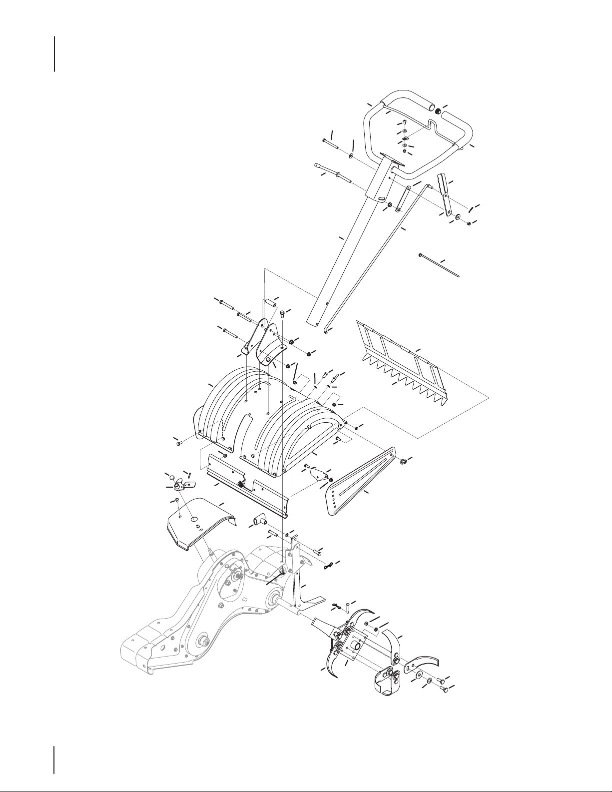
Ref. Part Number Description
1. 686-0044B End Cover Assembly
2. 710-0597 Hex Head Screw, ⁄-20 x 1
3. 710 -0604A Hex Head Screw, ⁄-18 x .625
4. 710-123 8 Hex Head Screw, ⁄-18 x .875
5. 710 -300 8 Hex Head Screw, ⁄-18 x .75
6. 712-0406 3 Nylon Hex Lock Nut, ⁄-18
7. 712-04064 Nylon Hex Lock Nut, ⁄-20
8. 712-0406 5 Flange Lock Nut, ⁄-16
9. 712- 0421 Wing Nut, ⁄-18
10. 715 - 0108 Spirol Pin
11. 926-0106 Cap Nut, ⁄ Rod
12. 731- 05512 Hole Plug
13. 732-04320 Torsion Spring
14. 738-04320 Shoulder Screw, .405 x .435 ⁄-18
15. 938-0533 Shoulder Screw, .498 x 1.635
16. 938-0849 Stop Screw
17. 747-0432 Tiller Flap Rod
18. 750 -05349 Spacer
19.. 786-0090A Side Shield
20. 786 - 0113 A Rear Tine Shield
21. 786 -04092 Reverse Stop Arm
22. 786-04104 Drag Bar
23. 786-04352A Tine Shield Mounting Bracket
24. 786- 04355A Tine Shield
25. 786-04356 Adjustable Depth Bar
26. 786-04363 Tail Bracket, LH
27. 786-04364 Tail Bracket, RH
Ref. Part Number Description
28. 649-04098 Upper Handle Assembly
29. 6 86- 04135 Reverse Handle Assembly
30. 710-0189 Hex Head Screw, ⁄-18 x 3.00
31. 710 - 059 9 Self-Tapping Screw, ⁄-20 x ⁄
32. 731-04735 Handle Select
33. 720-0278A Foam Handle Grip
34. 710-3288 Hex Head Screw, ⁄-20 x 1.62
35. 731-06253A Handle Cover
36. 735 -04105 Plug End
37. 736-0242 Bell Washer, .340 x .872 x .060
38. 946-04504 Reverse Cable
39. 946- 04506 Forward Cable
40. 747-04789 Clutch Bail
41. 750- 0885A Spacer, .322 x .625 x 2.00
42. 786-0340B Handle Crank
43. 786-04344 Handle Bracket, RH
44. 786-04345 Handle Bracket, LH
45. 786 -04358 Retainer Nut Bracket
46. 686-04144 Front Bumper
47. 731- 06529 Belt Cover
48. 736-0173 Flat Washer, .28 x .74 x .063
49. 738-0440 Spacer, .375 x .165
50. 710-04605 Hex Head Screw, ⁄-18 x 1.50
51. 720-04173 Reverse Handle Grip
52. 936 -0176 Flat Washer, .265 x .938 x .120
53. 936-0451 Saddle Washer, .320 x .930 x .060
1111
Page 12
Model Series 400
3
2
1
39
30
22
22
34
36
40
38
28
11
21
3
27
24
33
5
7
8
16
19
25
2
12
15
20
10
21
11
29
4
6
17
24
7
31
3
23
9
13
26
14
37
35
6
9
18
1212
Page 13
Model Series 400
Ref. Part Number Description
1. 634- 04736 Complete Whl. Ass., 13 x 5 x 6
634 -04735 Rim, 6.0 X 3.25
734-04163A Tire, 13 x 5 x 6
2. 714-0143A Klik Pin
3. 684-04168 Idler Pulley Assembly
4. 710 - 0331 Hex Head Screw, ⁄-24 x 2.25
5. 710 - 0170 Hex Head Screw, ⁄-24 x .625
6. 710-0599 Self Tapping Screw, ⁄-20 x .500
7. 710-0606 Hex Head Screw, ⁄-20 x 1.50
8. 710-0672 Hex Head Screw, ⁄-18 x 1.25
9. 710-1880 Hex Head Screw, ⁄-18 x .75, Patch
10. 73 6 - 0315 Washer, Flat, .760 x 1.50 x .120
11. 712- 04 064 Nylon Hex Lock Nut, ⁄-20
12. 712-0700 Nut, 9/16-18, Flange Lock
13. 718- 04407 Hub, ⁄ Spline
14. 732-04085 Extension Spring, .480 OD X 5.00 LG
15. 732-04276A Extension Spring, LT5 PTO
16. 936 -0 119 Lock Washer, ⁄
17. 736-0173 Washer, .28 x .74 x .063
18. 714-04043 Cotter Pin, Bow Tie
19. 736-0343 Flat Washer, .330 X 1.25 X .120
Ref. Part Number Description
20. 936-0452 Bell Washer, .396 x 1.140 x .095
21. 736-3092 Flat Washer, .265 x 1.0 x .030
22. 738-04425 Shoulder Screw, .342 x .335 ⁄-28
23. 748-04 087A Pivot Idler Spacer
24. 750- 04571 Shoulder Spacer, .260 x .785 x .538
25. 750-0 4907 Pivot Idler Spacer
26. 1916 657 V-Belt, 4L x 25.375 Long
27. 19166 58 V-Belt, 3L x 29.125 Long
28. 756-0419 8A Engine Pulley
29. 756- 04355 Transmission Pulley
30. 756-0625 Cable Roller
31. 786-04312 Idler Bracket, Forward
32. 786-04343 Cover Plate
33. 786-04346 Idler Bracket, Reverse
34. 786-04 416A Mounting Frame, RH
35. 786 -0 4 415B Mounting Frame, LH
36. 786-04357 Pulley Bracket
37. 786-0 4371 Pulley Shield
38. 642- 04071 Tine Assembly, LH
39. 642-04072 Tine Assembly, RH
40. 911- 0415 Clevis Pin, .375 x 1.75
1313
Page 14
Model Series 400
12
8
16
20
19
2
22
18
15
6
2
2
4
14
7
21
5
19
20
7
14
13
17
21
14
18
23
9
18
10
6
18
13
1
21
7
11
2
2
14
7
21
3
1414
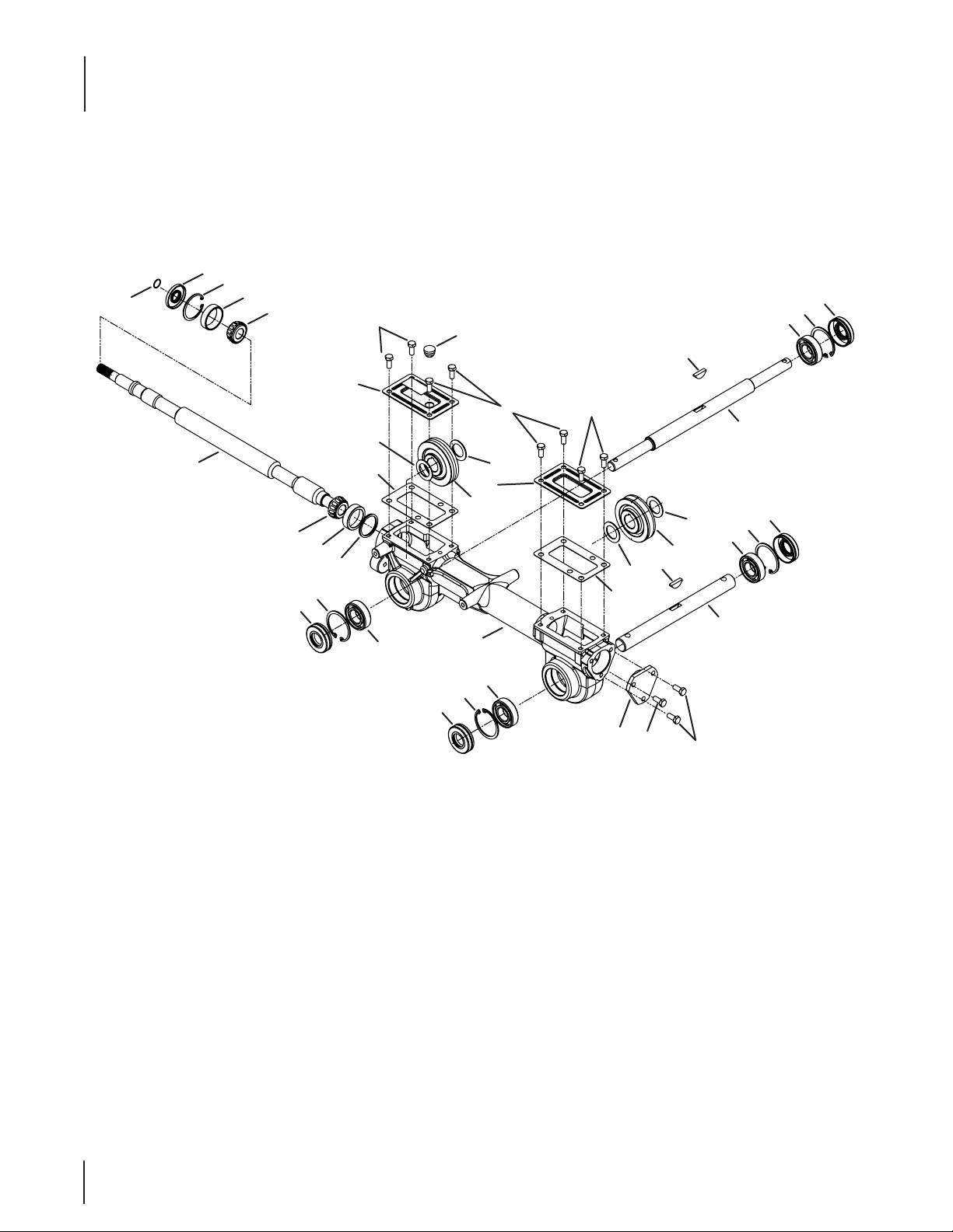
Page 15
Ref. Part Number Description
918 - 0 4815A Transmission Assembly
1. 919 - 0 4184A Housing, Transmission
2. 710-30 08 Hex Screw, 5/16-18, .75, Gr5
3. 911- 048 4 4 Shaft, Tiller
4. 911- 04854 Shaft, Wheel
5. 911-05028 Shaft, Worm
6. 714 -04059 Key, Hi Pro .25 x 1.062
7. 716-020 4 Retaining Ring
8. 716 - 0 4102 Retaining Ring, Int
9. 917-04380 Worm Gear, 61t, RH
10. 917-04381 Worm Gear, 30t, LH
11. 918- 04435 Bearing Cover
12. 921-04030 Seal, Oil, .750 Shaft x 1.783 Bore
13. 921-04229 Gasket, Gear Housing
14. 721-04232 Seal, Oil, 1.00 Shaft x 2.00 Bore
15. 721-04271 Rubber Plug, Oil
16. 732- 0614 Wire Ring
17. 736-04305 Washer, Flat, 1.50 x 1.75 x .062
— 736-04306 Washer, Flat, 1.50 x 1.75 x .005
— 736-04307 Washer, Flat, 1.50 x 1.75 x .03
— 736-04308 Washer, Flat, 1.50 x 1.75 x .010
18. 736 -074 5 Washer, Flat, 1.010 x 1.56 x .060
19. 9 41- 04298 Cone Bearing
20. 941-0429 9 Bearing Cup
21. 741- 3114 Ball Bearing
22. 786- 04366 Cover, Transmission
23. 786-04392 Cover, Transmission
* — The at washers listed are used as required to obtain .005 to
.015 in allowable end play on the drive shaft.
Model Series 400
1515
Page 16
Model Series 450
46
32
30
44
30
45
41
33
34
35
38
23
34
40
24
26
17
13
14
28
10
21
16
3
22
6
19
2
27
31
39
38
4
20
15
20
8
9
1
43
63
49
50
31
51
48
34
52
12
35
34
37
11
29
25
34
59
60
47
42
5
60
53
54
62
31
18
7
61
64
36
55
56
58
57
1616
Page 17
Model Series 450
Ref.
1. 747-1152 Shaft Rod
2. 649-0034 Lower Handle Tube Assembly
3. 649-0041 Upper Handle Assembly
4. 710- 0946 Screw, 1/4-20 x 0.625
5. 710-3005 Hex Head Screw, 3/8-16:1.25
6. 710-3056 Hex Head Screw, 5/16-18 x 3.25
7. 9 11- 0 415 Clevis Pin, .375 X 1.75
8. 712-0324 Hexlock Nut, 1/4-20
9. 712- 0379 Flangelock Nut, 3/8-24
10. 912- 042 9 Hexlock Nut, 5/16-18
11. 710-1307 Stud, 5/16-18 x .75
12. 720-0210A Small Tee Knob
13. 720 -0278A Foam Grip, .970 x 11.0
14. 720- 0313 Grip, .1875 x 1.00
15. 726-0273 Battery Clamp, 5/16
16. 7 26- 0317 Cable Tie, 8.5 LG
17. 735- 0246A End Plug
18. 9 36 -0117 Washer, Flat, .385 x .620 x .033
19. 736 -0242 Washer, Bell, .340 x .872 x .060
20. 736-3090 Washer, Flat, .260 x .720 x .060
21. 938-0958 Spacer, Shoulder, .50 x .190 x .360
22. 747-1219 Clutch Bail
23. 784- 0190 Handle Adjustment Crank
24. 78 4-0191 Hex Nut Retainer Bracket
25. 7 86- 0120 Tiller Depth Control
26. 786 -0181 Shaft Rod Lever
27. 735-0127 Washer, Rubber, .33 ID x .125
28. 914- 0104 Cotter Pin, .072 x 1.12 LG
29. 686-0044B End Cover Assembly
30. 710 -0176 Hex Head Screw, 5/16-18 x 2.75
31. 710-3008 Hex Head Screw, 5/16-18 x .75
32. 710-3022 Hex Head Screw, 3/8-16 x 2.75
Part Number Description
Ref.
33. 710-0 4482 Hex Head Flange, 3/8-16 x .875
34. 712- 04063 Flangelock Nut, 5/16-18
35. 712-040 65 Flangelock Nut, 3/8-16
36. 712- 0421 Wing Nut, 5/16-18 W/ Bell Washer
37. 926 - 0106 Speed Nut Cap, 1/4 ROD
38. 736-0204 Washer, Flat, .344 x .62 x .033
39. 938-0849 Screw, Hex, 5/16-18 x .75
40. 747-0432 Tiller Flap Rod
41. 750-0885A Spacer, .322 x .625 x 2.00
42. 786-0090A Side Shield
43. 78 6- 0113A Rear Tine Shield
44. 786-0176 RH Handle Mount Bracket
45. 786 - 0177 LH Handle Mount Bracket
46. 786-0178A Tine Shield
47. 786-0179 FRT Tine Shield Bracket
48. 786-0180 FRT Tine Shield Spacer Bracket
49. 686-0109A Shift Crank Assembly
50. 710-1652 Screw, ⁄-20 x .625
51. 715-0120 Spiral Pin, ⁄ x 1.0
52. 784-0208D Shift Cover
53. 911 - 0415 Clevis Pin
54. 712-30 54 Hex Nut, ⁄-24
55. 742-0305A 13” Articulating Tine
56. 938-0689 Shoulder Bolt
57. 936-0253 Bell Washer, .515” ID x 1.14” OD
58. 938-0688 Shoulder Bolt
59. 784-0160 Tine Adapter Assembly, 18”
60. 714-04043 Internal Cotter Pin
61. 936 -0169 Lock Washer
62. 784- 0161 Tine Adapter Plate
63. 731-07556 Cap
64. 936 -0208 Washer, Flat, .51 x 1.5 x .07
Part Number Description
1717
Page 18
Model Series 450
26
36
37
18
27
9
19
31
10
20
17
24
13
3
7
6
21
5
41
30
6
14
1
2
4
32
35
33
8
25
28
23
22
16
1818
34
42
38
12
40
11
15
39
32
Wheel shaft shown
for reference only.
33
29
Page 19

Model Series 450
Ref.
1. 6 86 -0111 Belt Cover Bracket Assembly
2. 710 -0170 Hex Bolt, ⁄-24 x .625
3. 710- 0513 Hex Bolt, ⁄-28 x .75”
4. 710- 0520 Hex Washer Screw, ⁄-16 x 1.50”
5. 710-1039 Hex Bolt, ⁄-24 x 1.0
6. 710-1652 Hex Washer Screw
7. 710 -3005 Hex Cap Screw, ⁄-16 x 1.25
8. 712-0266A Lock Jam Nut, ⁄-16
9. 712- 04063 Flangelock Nut, 5/16-18
10. 914 -010 4 Internal Cotter Pin
11. 912-3 066 Hex Nut, 1/2-20
12. 936-0 921 Washer, Lock, 1/2
13. 936 -0176 Flat Washer, .25 ID x .93 OD
14. 936-0271 Spring Washer, .317 ID x .625 OD
15. 750-0194 Hub, .636 ID x 1.00 OD x .94
16. 936-0452 Bell Washer, .396 ID x 1.14 OD
17. 738-0876A Shoulder Nut, ⁄-20
18. 9 46-1117 Clutch Cable
19. 747-1159 Idler Pulley Rod
20. 954-0434 V-Belt
21. 756- 0405 Flat Idler w/ Flange, 3.75 OD
Part Number Description
Ref.
22. 756-0971 Outer Engine Pulley Half
23. 756- 0972 Inner Engine Pulley Half
24. 75 6-116 2 Input Pulley
25. 786-0064A Idler Bracket
26. 786 -0185A Belt Keeper Bracket
27. 786-0187 Shift Cover Bracket
28. 786 -0193 Idler Belt Keeper
29. 934-04365A Wheel Assembly, 16.0 x 4.6 x 8
30. 936-3020 Flat Washer, .271 ID x .630 OD
31. 784-0158A Belt Cover
32. 710-0606 Hex Head Screw, ⁄-20
33. 712-0406 4 Flange Lock Nut, ⁄-20
34. 710-0382 Hex Bolt, ⁄-13 x 5.0
35. 712-04150 Flange Lock Nut, ⁄-13
36. 723- 0381† Counterweight, 40 lbs.
37. 936-0326 Flat Washer
38. 936-0179 Washer, Flat, 1/2 x 1.25 x .100
39. 710-0653 Hex Screw, ⁄-20 x .375
40. 731-1595† Counterweight
41. 712-0392 Lock Nut
42. 710-050 6 Hex Head Screw, 1/2-13 x 5.50
Part Number Description
† If Equipped
1919
Page 20
Model Series 450
20
3
16
28
11
11
10
34
35
29
16
16
37
37
36
47
41
38
38
45
27
15
38
38
48
19
14
21
49
32
1
33
46
31
37
29
13
16
42
30
37
12
17
28
12
16
46
5
33
51
2
6
7
23
44
40
50
38
24
9
38
25
39
18
43
26
8
47
4
36
22
2020
Page 21
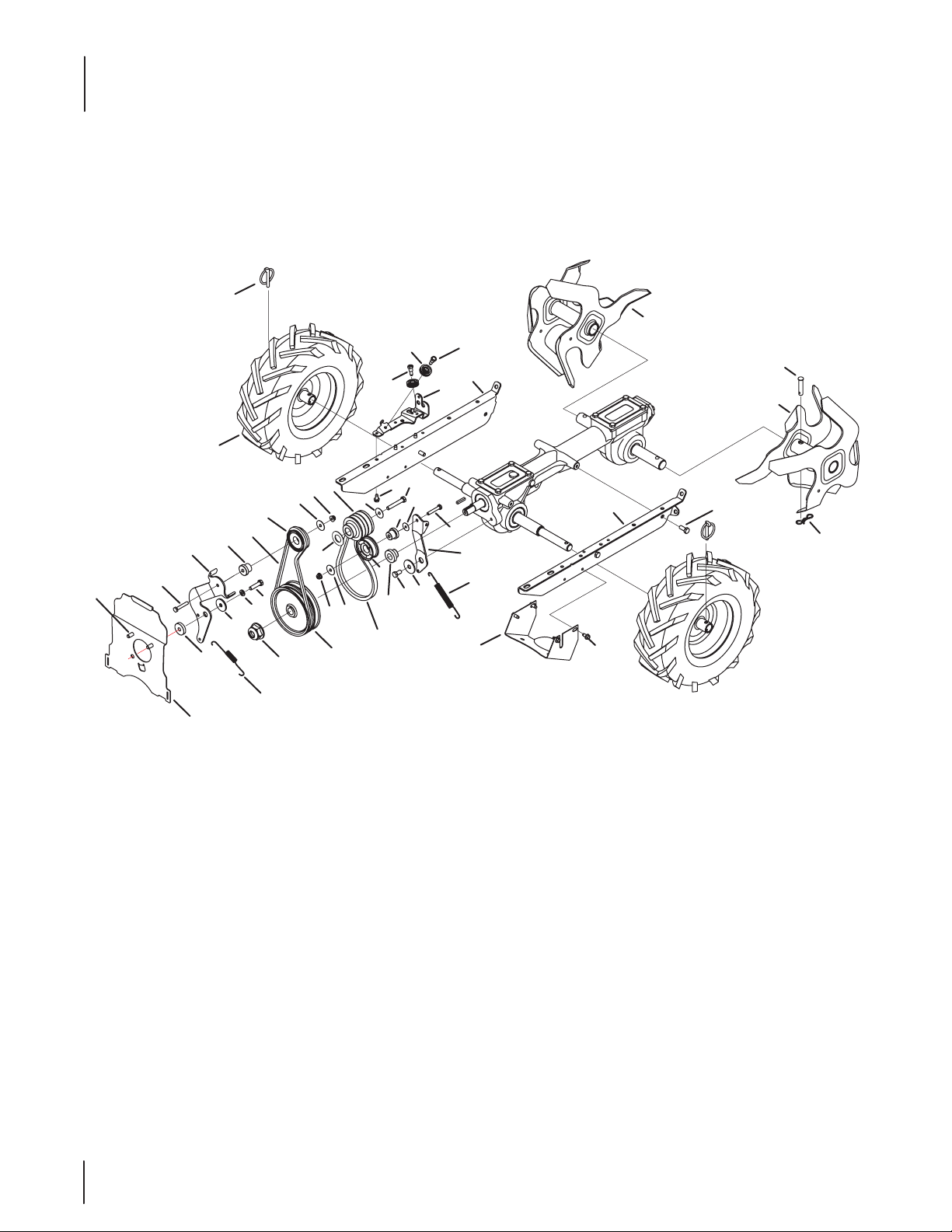
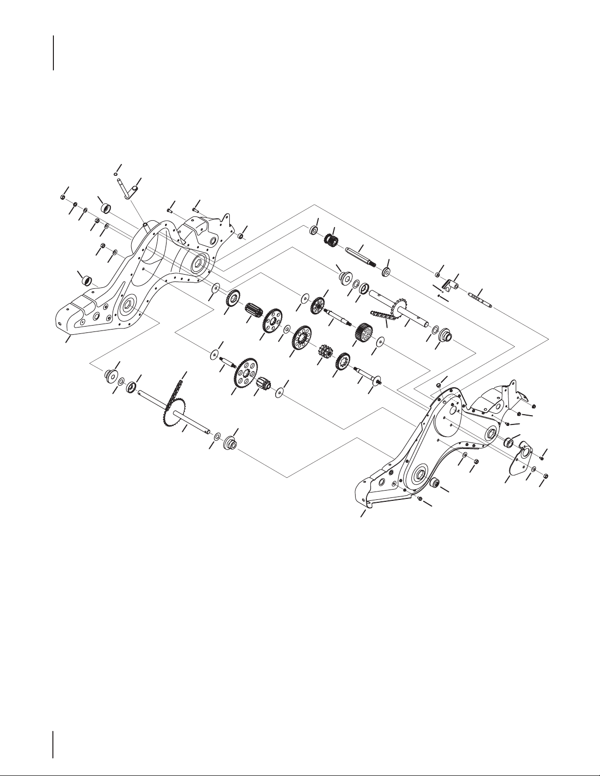
Model Series 450
Ref.
1. 611- 0021 Shaft Assembly, Tine, 18T
2. 611- 012 8 Shaft Assembly, Jack
3. 611-0129 Shaft Assembly, Shift Input
4. 611- 04 074 A Shaft Assembly, Wheel, 33T
5. 617-0058 Gear Assembly, 30T Reverse Idler
6. 617- 0 059 Gear Assembly, 30T Tine Idler
7. 617- 0 0 60 Sprocket Assembly, 9T Tine Input
8. 617- 0061 Sprocket Assembly, 10T Whl Input
9. 617-0062 Gear Assembly, 11T
10. 686-0108A RH Chain Case Housing Assembly
11. 710-0376 Hex Head Screw, 5/16-18 x 1.00
12. 710-1652 Screw, 1/4-20 x 0.625
13. 710 -04 484 Screw, :5/16-18 x 0.75
14. 750-0664 Spacer, .505 ID x .88 OD x .440
15. 711-13 4 9A Input Shaft, .75
16. 712- 0378 Nut, Hex, 7/16-20
17. 712-04063 Nut, Flangelock, 5/16-18
18. 913-0367 Endless Chain, #420 x 50 Links
19. 913-0484 Endless Chain, #50 x 54 Links
20. 716- 0865 Snap Ring, .500
21. 717- 0853A Clutch Collar
22. 717-15 82A Gear Spur, 44T
23. 717-15 83 Gear Spur, 30T
24. 717-1584 Gear Spur, 30T
25. 717-158 5 Gear Spur, 44T
26. 717-1587 Gear Spur, 44T
Part Number Description
Ref.
27. 717-159 4 Gear Spur, 16T
28. 921-0378 Shaft Seal, 1.0
29. 721- 0379 Shaft Seal, .75
30. 786-0238 Positioner Gear Bracket
31. 726- 0277 Tapered Cap Plug
32. 732- 04778 Compression Spring, .230 OD
33. 936 -0163 Washer, Flat, 1.03 x 1.62 x .03
34. 936 -0171 Washer, Lock, 7/16
35. 936- 0226 Washer, Flat,.474 x .879 x .064
36. 936-0351 Washer, Flat, .760 ID x 1.50 OD
37. 736-0407 Washer, Bell,.45 x 1.00 x .062
38. 736 -0518 Washer, Thrust, .445 x 1.92 x .060
39. 736-3088 Washer, Flat,1.595 x .635 x .062
40. 6 86- 0 4129 LH Chain Case Housing
41. 950 -0671 Spacer, .75 x 2.0 x .50
42. 738- 0645 Shaft Detent, .5 DIA
43. 738-0648 Shaft, Jack, .625 x 2.385
44. 738-04424A Shaft, Jack, .6250 x 5.0050
45. 941- 0600 Ball Bearing, 17 x 40 x 12:6203
46. 941- 0420 Flange Bearing, 1.0 x 2.5 x 1.38
47. 741- 0421 Flange Bearing, .75 x 2.5 x 1.38
48. 941-05 63 Ball Bearing, 17 x 40 x 12:6203
49. 741- 0862 Ball, Detent, .250
50. 750- 0258 Spacer, .315 x .750 x .375 LG
51. 950-0570 Spacer, 1.0 ID x 2.0 OD x.5 LG
— 9 86-04074B Gear Case Assembly Complete
Part Number Description
2121
Page 22
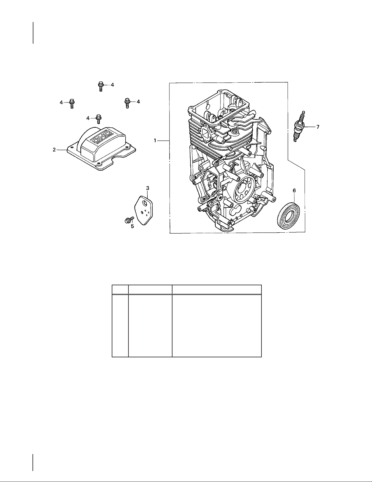
Honda GC190LA Cylinder
CYLINDER
22
22
Ref. Part Number Description
12000-Z1A-0000
1.
2. 12310-Z0J-000 Head Cover
3. 12355-ZL8-000 Breather Cover
4. 90013-883-000 Flange Bolt, 6 X 12
5. 90014-952-000 Flange Bolt, 6 X 14
6. 91201-Z L8- 003 Oil Seal, 25.4 X 62 X 6
7. 98079-56846 Spark Plug (BPR6ES NGK)
Cylinder Assembly
Page 23
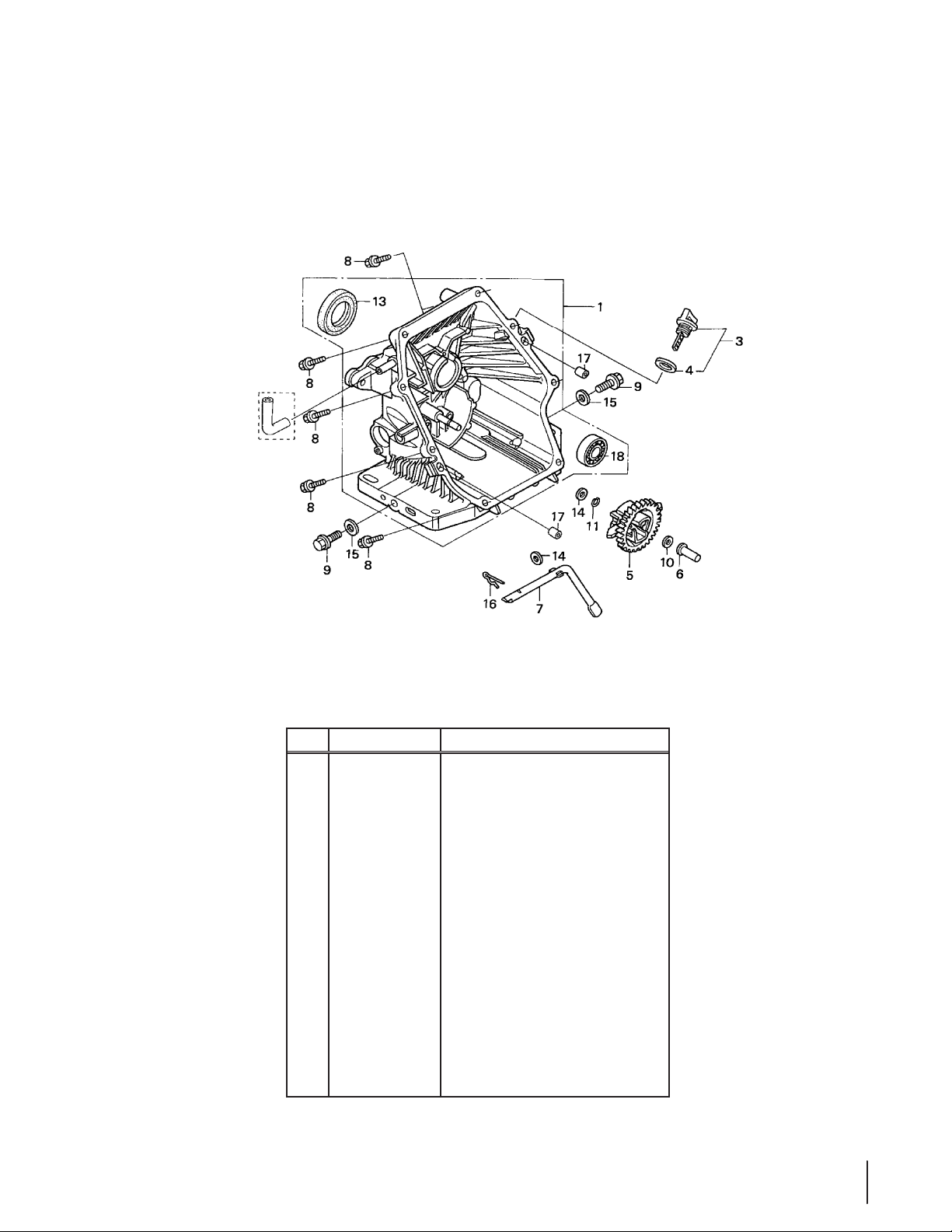
Honda GC190LA Crankcase Cover
OIL PAN
Ref. Part Number Description
1. 11300-Z1A-600 Crankcase Cover Assembly
3. 15600-ZF0-003 Oil Filler Cap Assembly
4. 1562 5-ZE1- 003 Oil Filler Cap Gasket
5. 16510-ZL8- 000 Governor Assembly
6. 16531-ZE1- 000 Governor Slider
7. 16541-ZL8-000 Governor Arm Shaft
8. 90121-952-000 Flange Bolt, 6 x 25
9. 90131- 896-650 Drain Plug Bolt
10. 90451-ZE1-000 Thrust Washer, 6mm
11. 90602-ZE1-000 Governor Holder Clip
13. 912 02 -Z L8- 003 Oil Seal, 28 x 41.25 x 6
14. 94101- 0680 0 Plain Washer, 6mm
15. 94109-12000 Drain Plug Washer, 12mm
16. 94251-08000 Lock Pin, 8mm
17. 94301-08200 Dowel Pin, 8 x 20
23
23
Page 24
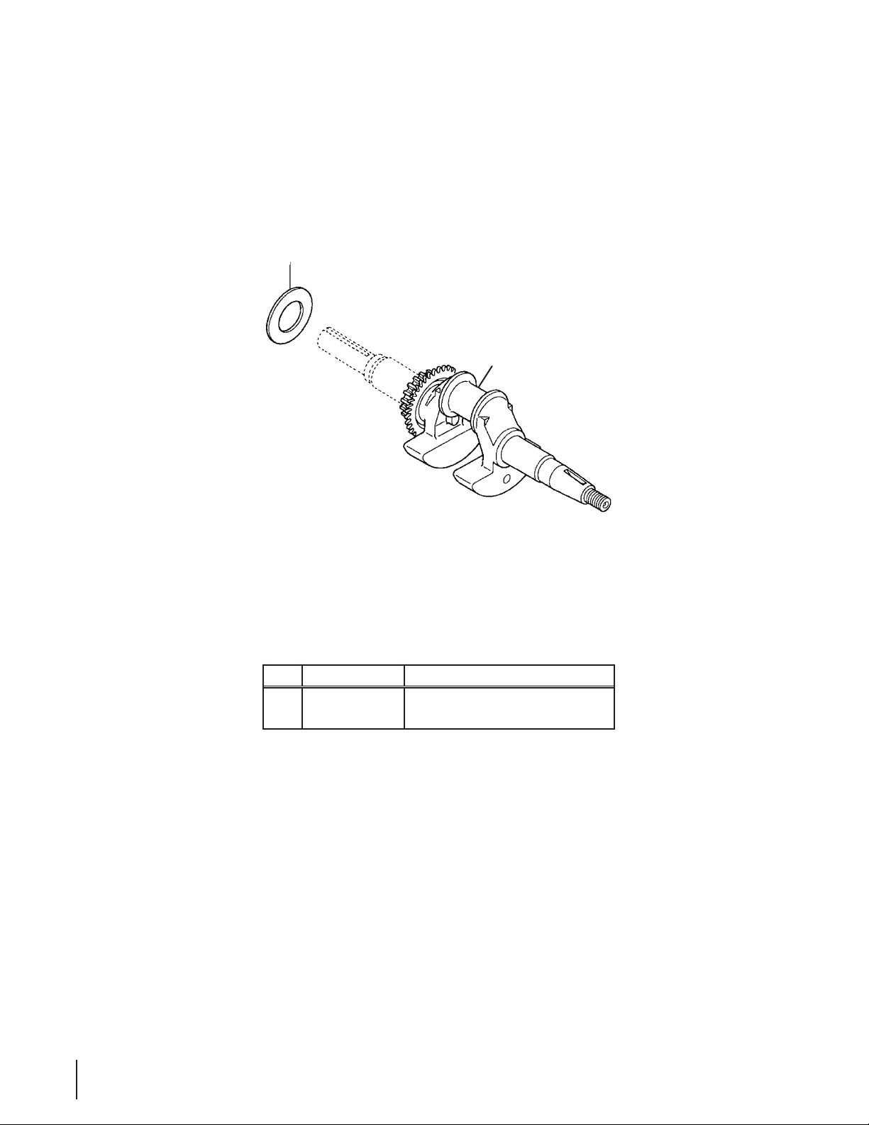
CRANKSHAFT
Honda GC190LA Crankshaft
2
1
24
24
Ref. Part Number Description
1. 13310-Z1A- 660 Crankshaft
2. 90402-ZL8-000 Thrust Washer
Page 25
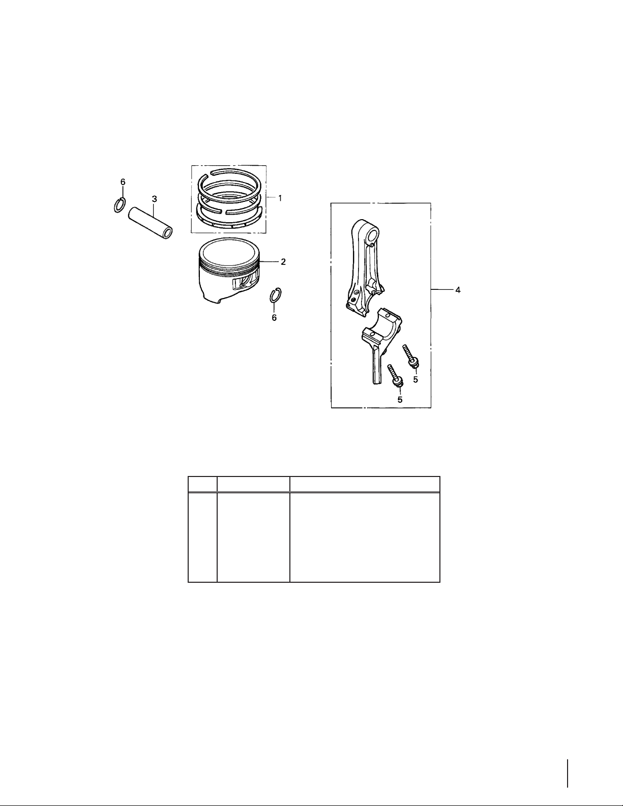
Honda GC190LA Piston
PISTON • CONNECTING ROD
Ref. Part Number Description
1. 13010-Z0Y- 014 Piston Ring Set (Teikoku)
2. 13101-Z0Y- 010 Piston
3. 13111- Z0Y- 000 Piston Pin
4. 13200-Z0Y-010 Connecting Rod Assembly
5. 90001-ZE1-000 Connecting Rod Bolt
6. 90551-ZE0-000 Piston Pin Clip, 13mm
25
25
Page 26
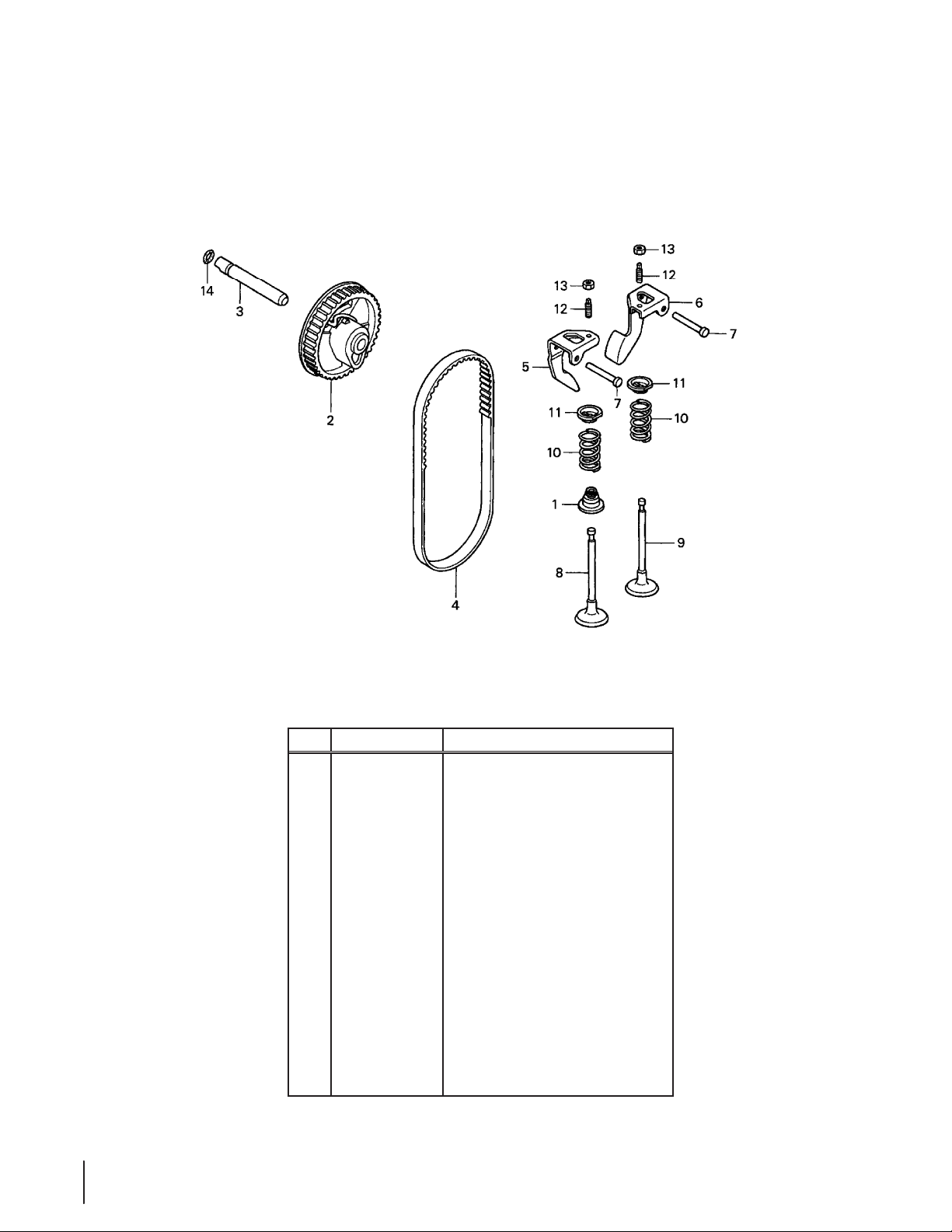
Honda GC190LA Camshaft
CAMSHAFT
26
26
Ref. Part Number Description
1. 12209 -Z M0- 003 Valve Stem Seal
2. 14320-Z0Y-000 Cam Pulley
3. 14324-ZL8- 000 Cam Pulley Shaft
4. 1440 0-Z0J - 014 Timing Belt, 84HU& G-200
5. 14431-Z0J-000 Internal Valve Rocker Arm
6. 14441-Z0J-000 External Valve Rocker Arm
7. 14461-ZL8-000 Rocker Arm Shaft
8. 14711-Z0J-000 Internal Valve
— 14711-Z0J-000 Internal Valve
9. 14721-ZL8-000 External Valve
10. 14751-ZL8-000 Valve Spring
11. 14771-Z0J-000 Internal Valve Spring Retainer
12. 90012-333-000 Tappet Adjustable Screw
13. 90206-001-000 Tappett Adjustble Nut
14. 91301-ZM0-V 31 O-Ring, 6.8 x 1.9
Page 27
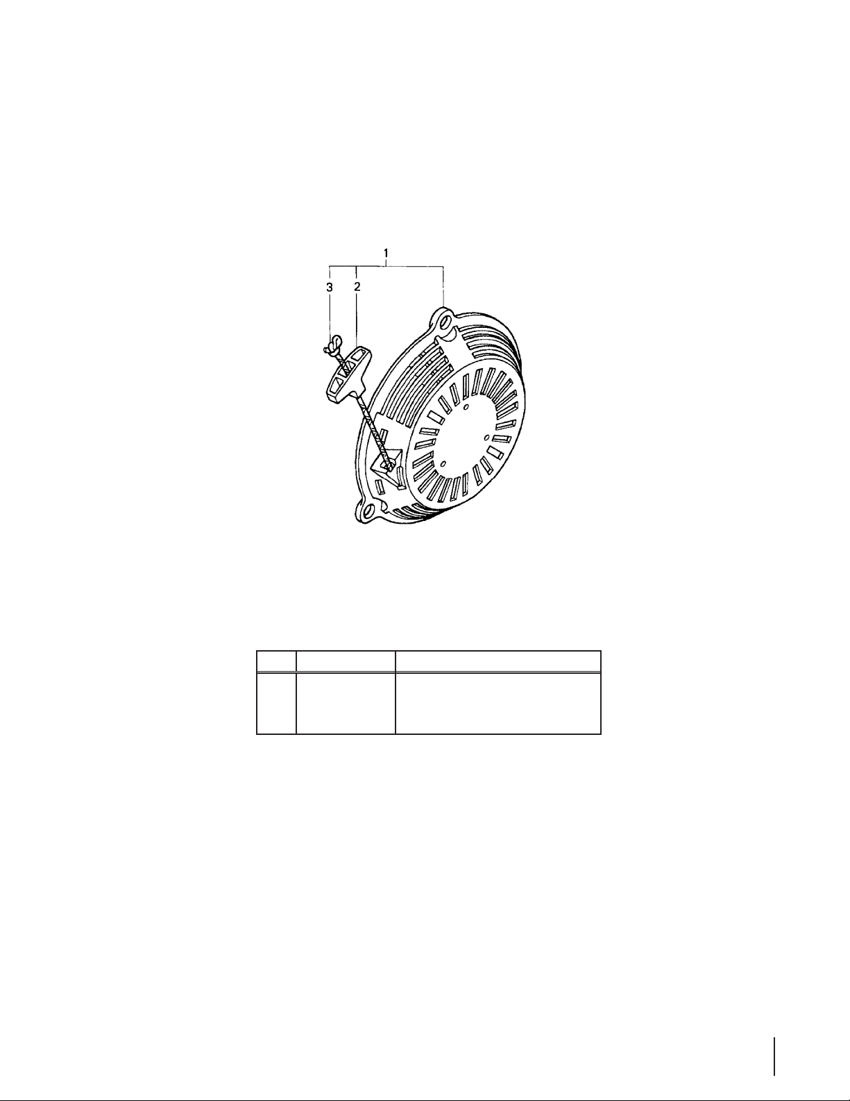
Honda GC190LA Recoil Starter
RECOIL STARTER
Ref. Part Number Description
28400-Z1A-013ZA
1.
2. 28461-ZL8-003 Recoil Starter Knob
3. 28462-ZL8-003 Recoil Starter Rope, #3.5 x 52”
Recoil Starter Assembly
27
27
Page 28
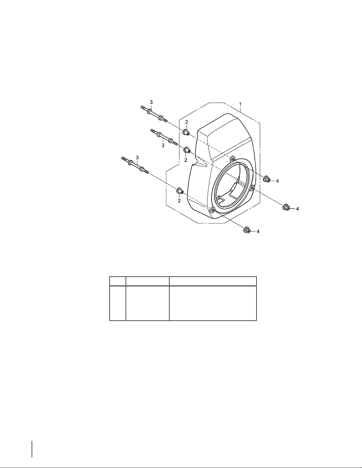
Honda GC190LA Fan Cover
28
28
Ref. Part Number Description
19611-Z1A-000ZA
1.
19619 -ZL8-30 0
2.
3. 90043-ZL8-000 Stud Bolt
4. 90201-ZM0-000 Flange Nut, 6mm
Fan Cover
Fan Cover Collar
Page 29

Honda GC190LA Carburetor
CARBURETOR
Ref. Part Number Description
1. 16010 -883- 015 Gasket Set
2. 16 013-ZL1- 00 3 Float Set
3. 16 015 -Z L8-003 Float Chamber Set
4. 16016-Z1A- 003 Screw Set
5. 16024 -124-760 Drain Screw Set
6. 16028-ZK7-591 Screw Set
7. 16029 -ZG 0-9 01 Screw Set
8. 16100-Z1A- 801 Carburetor Assembly, BB61K A
9. 16155 -ZL8-013 Float Valve
10. 16166 -Z1A-003 Main Nozzle
11. 16211-ZL8-000 Carburetor Insulator
Ref. Part Number Description
12. 16212-ZL8- 000 Insulator Gasket
13. 16221-887-800 Carburetor Gasket
14. 16228-ZL8-000 Carburetor Gasket (Choke Side)
15. 19650-ZL8-000 Air Guide
93500-05006-1H
16.
17. 95002-02650 Tube Clip, B6.5
95003-07008-60M
18.
19. 9 9101-124- 062 0 Main Jet, #62
— 99101-124-0650 Main Jet, #65
— 99101-124-0680 Main Jet, #68
Pan Screw, 5 x 6
Vinyl Bulk Hose (4X7X8000, 4X7X150)
29
29
Page 30

Honda GC190LA Air Filter
AIR CLEANER
30
30
Ref. Part Number Description
1. 15721-ZL8-000 Breather Tube
2. 17211 -ZL8 -0 2 3 Air Cleaner Element
3. 17220-ZL8-000 Air Cleaner Housing
4. 17228-ZL8-000 Air Cleaner Gasket
5. 17231-Z0 J -020 Air Cleaner Cover
6. 90003-ZL8-000 Flange Bolt, 6 x 112
Page 31

Honda GC190LA Muffler
MUFFLER
Ref. Part Number Description
1. 18310-Z0Y-000 Muer
2. 18321-Z0L-000 Muer Protector
4. 18381-ZL8-305 Muer Gasket
7. 90004-ZL8-000 Flange Bolt, 6 x 79
8. 90013-883-000 Flange Bolt, 6 x 12
10. 18350-ZL8-000 Spark Arrester
11. 18356-ZL8-000 Arrester Number Plate
12. 90055-ZE1-000 Tapping Screw, 4 x 6
13. 06180-Z0J-000 Spark Arrester Kit
31
31
Page 32

Honda GC190LA Fuel System
Ref. Part Number Description
1. 16700-Z0J-003 Fuel Pump Assembly
2. 16854-ZH8-000 Supporter Rubber, 107mm
3. 16882-ZL8-000 Tube, Diaphragm
4. 16910 -ZV4-015 Fuel Strainer
5. 16915-ZV4-000 Strainer, Suspension
6. 17511-Z0J -80 0 Fuel Tank
7. 17516-ZV0-000 Tank Mounting Rubber, B
8. 17519-Z L8-800 Fuel Tube
9. 17535-KE7-000 Collar
10. 17561-Z0J-000 Stay A, Fuel Tank
11. 1762 0 -Z0 J - 8 00 Fuel Cap Assembly
12. 17701-ZL8-800 Fuel Tank Tube
13. 17702-ZL8-800 Fuel Tube
14. 1770 3-Z L8-800 Fuel Return Tube
32
32
Ref. Part Number Description
15. 17 704-ZL8-800 Fuel Pump Tube
16. 80103-MG2-000 Rear Fender Cushion
90041-ZL8-000
17.
18. 90473-896-000 Washer, 6Mm
19. 90501-KA2-640 Collar, 14 X 6.1
20. 93404-06025-00 Bolt-Washer, 6 X 25
21. 93894-05014-00 Screw-Washer, 5 X 14
22. 94050-06000 Nut, Flange, 6mm
23. 95001-55033-40 Fuel Tube, 5.3 X 33
24. 95002-02080 Tube Clip, B8
25. 95002-02100 Tube Clip, B10
26. 95002-50000 Tube Clip, C9
27. 95002-70000 Tube Clip, C11
Fuel Tank Stud Bolt, 30mm
Page 33

Honda GC190LA Flywheel
FLYWHEEL
Ref. Part Number Description
1. 13331-357-000 Special Woodru Key, 25 x 18
2. 30500-Z0J-003 Ignition Coil Assembly
3. 31110 -Z 0J -0 13 Flywheel
5. 32195-Z0J-000 Stop Switch Wire
6. 36103-ZE1-000 Stop Switch Wire Holder
51125-Z0 L-0 0 3 Stop Switch Wire Holder
8. 90022-888-010 Flange Bolt, 6 x 20
9. 90213-S3Y-000 Flange Nut, 14mm
33
33
Page 34

Honda GC190LA Controls
CONTROL (1)
Ref. Part Number Description
1. 16500-ZL8-000 Control Assembly
2. 16551-ZL8 - 010 Governor Arm
3. 16555-ZL8-000 Governor Rod
4. 16561-Z0J-000 Governor Spring
5. 16562-ZL8-800 Throttle Return Spring
6. 16571-ZL8-000 Control Lever
7. 16574-ZE1-000 Lever Spring
8. 16575-ZL8-000 Control Lever Washer
9. 16578-ZE1-000 Control Lever Spacer
10. 16500-ZL8-000 Control Base
11. 16611-ZL8-000 Choke Control Rod
34
34
Ref. Part Number Description
12. 16613-893-000 Choke Rod Grommet
13. 19612-Z0L-000 Side Plate
14. 35120-ZL8-003 Engine Stop Switch Assembly
15. 90013-883-000 Flange Bolt, 6 x 12
16. 90014-952-000 Flange Bolt, 6 x 14
17. 90015-ZE5-010 Governor Arm Bolt
18. 90114-SA0-000 Self-lock Nut, 6mm
19. 93892-04012-00 Screw-Washer, 4 x 12
20. 94050-06000 Flange Nut, 6mm
21. 94103-04000 Plain Washer, 4mm
Page 35

35Notes
Page 36

170-T0B Air Cleaner & Muffler
36
Ref. Part Number Description
20 951-11285 Exhaust Pipe Gasket
21 712- 04214 Nut, M8
22 951-1215 6 Muer Assembly
23 710-05002 Bolt
30 951-108 06 Air Cleaner Housing
31 712-04213 Nut
32 710 -05102 Self-Tapping Bolt M4.2×16
34 9 51-12135 Silencer Plate
35 951-10794 Air Cleaner Assembly
36 951-10794 Air Cleaner Assembly
37 951-1213 6 Air Cleaner Cover
Page 37

170-T0B Carburetor
Ref.
Part Number Description
28 951-12124 Carburetor Assembly
29 9 51-11571 Carburetor Gasket Plate
a 951 -11177 Control Lever,Choke
b N/A Choke Shaft
c N/A Choke Plate
d N/A Throttle Shaft
e N/A Throttle Plate
f N/A Screw M3×5
g N/A Lock Washer
h N/A Idle Jet Assembly
i N/A Gasket, Throttle Plate
j N/A Idle Speed Adjusting Screw
k N/A Mixture Screw
l N/A Carburetor Body
Ref.
Part Number Description
m N/A Float Pin
n N/A Emulsion Tube
o N/A Needle Valve
p N/A Main Jet
q N/A Needle Valve Spring
r N /A Float
s 951-11589 Fuel Bowl Gasket
t N/A Fuel Bowl
u 9 51-113 4 8 Fuel Bowl Gasket
v 710-04945 Fuel Bowl Mounting Bolt
w 9 51-113 4 9 Fuel Drain Plug Gasket
x 710 -04938 Fuel Drain Plug
951-12119 Carburetor Kit - Major
(Incl Ref. l,m,n,o,p,q,r,s,u & w)
37
Page 38

170-T0B Crankcase
a
113
112
38
Page 39

170-T0B Crankcase
Ref.
Part Number Description
44 95 1-112 53 Piston Ring Set
45 9 51-116 32 Piston Pin Snap Ring
46 951-12007 Piston
47 951 -11633 Piston Pin
48 710 -0 4915 Bolt M6×12
49 9 51-11113 Air Shield
50 9 51-11573 Connecting Rod Assembly
51 951 -11356 Governor Arm Shaft
52 736- 04461 Washer 5.2×1.9
53 95 1-115 74 Governor Seal
54 714 -0 4074 Cotter Pin
55 951-1157 5 Camshaft Assy.
56 9 51-113 6 9 Radial Ball Bearing, 6205
57 951-1216 0 Crankshaft Assembly
58 951-10307 Woodru Key
59 951-1157 6 Governor Gear/Shaft Assembly
Ref.
Part Number Description
60 715 - 04092 Dowel Pin 7×14
61 715- 04089 Dowel Pin 9×14
62 9 51-11371 Crankcase Cover Gasket
63 9 51-12125 Cover Comp, Left Crankcase
64 710-04932 Bolt M8×32
65 9 51-11377 Oil Filler Plug Ass'y
65a 95 1-115 77 O-Ring
66 951 -11578 Oil Seal, 25×41.25×6
67 951-12155 Short Block
(Incl Ref. 4,20,25,26,38,
40,41,44-47,50-70
68 736-04440 Washer 10×16×1.5
69 710 -0490 6 Oil Drain Plug
112 951-10370 Oil Drain Plug & Washer Assembly
113 951 -11283 Oil Fill Plug Assembly
39
Page 40

170-T0B Fuel Tank
101a
Ref. Part Number Description
1 710-0 4968 Bolt M6×16
83 951-11067 Throttle Control Knob
84 951-12131 Primer Bracket
85 710-0 4928 Bolt M6×12
86 9 51-115 8 5 Governor Spring
87 951-10664 Throttle Linkage Spring
88 951-10665 Throttle Linkage
90 9 51-1110 6 Governor Arm
91 712- 04212 Nut M6
92 710-04908 Governor Arm Bolt
93 951-10650 Fuel Line Kit
94 951-117 00 Fuel Hose Clamp
95 710-04915 Bo lt M6×12
40
Ref. Part Number Description
96 951-10662 Dipstick Decoration Cover
97 710- 04905 Bolt
98 710 -0 4915 Bolt M6×12
100 951-11903 Oil Fill Tube O-Ring
101 951-10656 Oil Fill Tube
101a 951-11913 Oil Fill Tube Assembly
102 951-11904 Oil Fill Tube O-Ring
103 951-11912 Dipstick Assembly
104 951-10917 Fuel Cap Assembly
106 951-11933 Fuel Filter
107 951-12159 Fu el Ta nk
108 951-10651 Fuel Tank Nipple
Page 41

170-T0B Flywheel & Shroud
Ref.
Part Number Description
70 951-12126 Oil Seal 25×41.25×6
71 951-10792 Ignition Coil Assembly
72 710-04919 Bolt M6×25
73 951-10805 Flywheel
74 951-10909 Fan, Cooling
75 951-10911 Pulley, Starter
76 712- 04209 Nut, Special, M14×1.5
77 710-04915 Bo lt M 6×12
Ref.
Part Number Description
79 9 51-115 8 3 Blower Housing
80 736 -04455 Flat Washer
81 710 -0 4974 Bolt M6×10
82 9 51-12127 Recoil Starter
109 712- 04212 Nut, M6
110 710 -04918 Bolt M6×20
111 951 -1110 9 Blower Housing Shield
41
Page 42

170-T0B Cylinder Head
114
a
42
Page 43

170-T0B Cylinder Head
Ref.
Part Number Description
1 710-0 4968 Bo lt M6×16
2 951-11054 Valve Cover
3 731- 07059 Breather Hose
3a 726 -0 4101 Hose Clamp
4 95 1-115 65 Valve Cover Gasket
5 95 1-11892 Rocker Arm Assembly
6 751-11124 Nut, Pivot Locking
7 751-1112 3 Adjusting Nut ,Valve
8 95 1-11893 Rocker Arm
9 710-0 4902 Bolt, Pivot
10 951-11895 Push Rod Guide
11 951-12000 Retainer, In.Valve Spring
12 951-120 02 Adjuster, Exh Valve
13 9 51-120 03 Retainer, Ex.Valve Spring
14 951-120 0 4 Valve Spring
15 9 51-118 94 Intake Valve Seal
16 710 -04933 Bolt M8×55
17 951-10668A Cylinder Head Assembly
(Incl Ref. 4,6-15,17,20,
25,26,38,42 & 43)
18 951-10292 Spark Plug/F6Rtc
Ref.
Part Number Description
19 710 -05276 Muer Stud M8×36
19 951-10657 Muer Stud Assembly
24 710-05101 S t u d M 6×11 0
25 9 51-115 67 Carburetor Insulator Gasket
26 9 51-115 6 8 Carburetor Insulator
27 95 1-115 69 Carburetor Gasket
38 9 51-11572 Gasket, Cylinder Head
39 951-106 48 Push Rod
40 951-11899 Tap pet
41 715-04 090 Dowel Pin 10×16
42 951-10647A Valve Kit
43 951-106 47A Valve Kit
114 951-11063A Valve Cover Kit
951-10819 Cylinder Head Service Kit
(Incl Ref. 4,15,16 & 38)
951-1212 0 Gasket Kit, External
(Incl Ref. 4,20,25,26,27,29 & 68)
951-12121 Gasket Kit, Complete
(Incl Ref. 4,20,25,26,27,29,38,52,
53,62,66,68 & 70)
43
Page 44

170-V0B Air Cleaner & Muffler
44
Ref. Part Number Description
20 951-11285 Exhaust Pipe Gasket
21 712- 04214 Nut, M8
22 751-122 94 Muer Assembly
23 710-05002 Bolt
30 951-108 06 Air Cleaner Housing
31 712-04213 Nut
32 710 -05102 Self-Tapping Bolt M4.2×16
34 9 51-12135 Silencer Plate
35 951-10794 Air Cleaner Assembly
36 951-10794 Air Cleaner Assembly
37 951-1213 6 Air Cleaner Cover
Page 45

170-V0B Carburetor
Ref.
Part Number Description
28 951-10797 Carburetor Assembly
29 9 51-11571 Carburetor Gasket Plate
a 951 -11177 Control Lever,Choke
b N/A Choke Shaft
c N/A Choke Plate
d N/A Throttle Shaft
e N/A Throttle Plate
f N/A Screw M3×5
g N/A Lock Washer
h N/A Idle Jet Assembly
i N/A Gasket, Throttle Plate
j N/A Idle Speed Adjusting Screw
k N/A Mixture Screw
l N/A Carburetor Body
Ref.
Part Number Description
m N/A Float Pin
n N/A Emulsion Tube
o N/A Needle Valve
p N/A Main Jet
q N/A Needle Valve Spring
r N /A Float
s 951-11589 Fuel Bowl Gasket
t N/A Fuel Bowl
u 9 51-113 4 8 Fuel Bowl Gasket
v 710-04945 Fuel Bowl Mounting Bolt
w 9 51-113 4 9 Fuel Drain Plug Gasket
x 710 -04938 Fuel Drain Plug
951-12119 Carburetor Kit - Major
(Incl Ref. l,m,n,o,p,q,r,s,u & w)
45
Page 46

170-V0B Crankcase
a
113
112
46
Page 47

170-V0B Crankcase
Ref.
Part Number Description
44 95 1-112 53 Piston Ring Set
45 9 51-116 32 Piston Pin Snap Ring
46 951-12007 Piston
47 951 -11633 Piston Pin
48 710 -0 4915 Bolt M6×12
49 9 51-11113 Air Shield
50 9 51-11573 Connecting Rod Assembly
51 951 -11356 Governor Arm Shaft
52 736- 04461 Washer 5.2×1.9
53 95 1-115 74 Governor Seal
54 714 -0 4074 Cotter Pin
55 951-1157 5 Camshaft Assy.
56 9 51-113 6 9 Radial Ball Bearing, 6205
57 951-1216 0 Crankshaft Assembly
58 951-10307 Woodru Key
59 951-1157 6 Governor Gear/Shaft Assembly
Ref.
Part Number Description
60 715 - 04092 Dowel Pin 7×14
61 715- 04089 Dowel Pin 9×14
62 9 51-11371 Crankcase Cover Gasket
63 9 51-12125 Cover Comp, Left Crankcase
64 710-04932 Bolt M8×32
65 9 51-11377 Oil Filler Plug Ass'y
65a 95 1-115 77 O-Ring
66 951 -11578 Oil Seal, 25×41.25×6
67 951-12155 Short Block
(Incl Ref. 4,20,25,26,38,
40,41,44-47,50-70
68 736-04440 Washer 10×16×1.5
69 710 -0490 6 Oil Drain Plug
112 951-10370 Oil Drain Plug & Washer Assembly
113 951 -11283 Oil Fill Plug Assembly
47
Page 48

170-V0B Fuel Tank
101a
Ref. Part Number Description
1 710-0 4968 Bolt M6×16
83 951-11067 Throttle Control Knob
84 951-12131 Primer Bracket
85 710-0 4928 Bolt M6×12
86 9 51-115 8 5 Governor Spring
87 951-10664 Throttle Linkage Spring
88 951-10665 Throttle Linkage
90 9 51-1110 6 Governor Arm
91 712- 04212 Nut M6
92 710-04908 Governor Arm Bolt
93 951-10650 Fuel Line Kit
94 951-117 00 Fuel Hose Clamp
95 710-04915 Bo lt M6×12
48
Ref. Part Number Description
96 951-11914 Dipstick Decoration Cover
97 710- 04905 Bolt
98 710 -0 4915 Bolt M6×12
100 951-11903 Oil Fill Tube O-Ring
101 951-10656 Oil Fill Tube
101a 951-11913 Oil Fill Tube Assembly
102 951-11904 Oil Fill Tube O-Ring
103 951-11912 Dipstick Assembly
104 951-10917 Fuel Cap Assembly
106 951-11933 Fuel Filter
107 951-12159 Fu el Ta nk
108 951-10651 Fuel Tank Nipple
Page 49

170-V0B Flywheel & Shroud
Ref.
Part Number Description
70 951-12126 Oil Seal 25×41.25×6
71 951-10792 Ignition Coil Assembly
72 710-04919 Bolt M6×25
73 951-10805 Flywheel
74 951-10909 Fan, Cooling
75 951-10911 Pulley, Starter
76 712- 04209 Nut, Special, M14×1.5
77 710-04915 Bo lt M 6×12
Ref.
Part Number Description
79 9 51-115 8 3 Blower Housing
80 736 -04455 Flat Washer
81 710 -0 4974 Bolt M6×10
82 9 51-12127 Recoil Starter
109 712- 04212 Nut, M6
110 710 -04918 Bolt M6×20
111 951 -1110 9 Blower Housing Shield
49
Page 50

170-V0B Cylinder Head
114
a
50
Page 51

170-V0B Cylinder Head
Ref.
Part Number Description
1 710-0 4968 Bo lt M6×16
2 951-11054 Valve Cover
3 731- 07059 Breather Hose
3a 726 -0 4101 Hose Clamp
4 95 1-115 65 Valve Cover Gasket
5 95 1-11892 Rocker Arm Assembly
6 751-11124 Nut, Pivot Locking
7 751-1112 3 Adjusting Nut ,Valve
8 95 1-11893 Rocker Arm
9 710-0 4902 Bolt, Pivot
10 951-11895 Push Rod Guide
11 951-12000 Retainer, In.Valve Spring
12 951-120 02 Adjuster, Exh Valve
13 9 51-120 03 Retainer, Ex.Valve Spring
14 951-120 0 4 Valve Spring
15 9 51-118 94 Intake Valve Seal
16 710 -04933 Bolt M8×55
17 951-10668A Cylinder Head Assembly
(Incl Ref. 4,6-15,17,20,
25,26,38,42 & 43)
18 951-10292 Spark Plug/F6Rtc
Ref.
Part Number Description
19 710 -05276 Muer Stud M8×36
19 951-10657 Muer Stud Assembly
24 710-05101 S t u d M 6×11 0
25 9 51-115 67 Carburetor Insulator Gasket
26 9 51-115 6 8 Carburetor Insulator
27 95 1-115 69 Carburetor Gasket
38 9 51-11572 Gasket, Cylinder Head
39 951-106 48 Push Rod
40 951-11899 Tap pet
41 715-04 090 Dowel Pin 10×16
42 951-10647A Valve Kit
43 951-106 47A Valve Kit
114 951-11063A Valve Cover Kit
951-10819 Cylinder Head Service Kit
(Incl Ref. 4,15,16 & 38)
951-1212 0 Gasket Kit, External
(Incl Ref. 4,20,25,26,27,29 & 68)
951-12121 Gasket Kit, Complete
(Incl Ref. 4,20,25,26,27,29,38,52,
53,62,66,68 & 70)
51
Page 52

270-V0 Muffler
21
23
23
22
20
19
19
52
Ref. Part Number Description
19 71 0 -04911 Muer Stud M8×36
19 951-12027 Muer Stud Assembly
20 951-11285 Muer Gasket
21 712- 04214 Nut,M8
22 951-1229 4 Muer Assembly
23 710-05002 Bolt
Page 53

24
270-V0 Carburetor Assembly
24
25
26
27
Ref.
Part Number Description
24 710-05101 Carburetor Stud M6×110
25 9 51-115 67 Carburetor Insulator Gskt
26 9 51-115 6 8 Carburetor Insulator Plate
27 95 1-115 69 Carburetor Gasket
28 951-10797 Carburetor Assembly
29 9 51-11571 Carburetor Gasket Plate
a N/A Control Lever,Choke
b N/A Choke Shaft
c N/A Choke Plate
d N/A Throttle Shaft
e N/A Throttle Plate
f N/A Screw M3×5
g N/A Lock Washer
h N/A Idle Jet Assembly
i N/A Gasket, Throttle Plate
j N/A Idle Speed Adjusting Screw
28
29
Ref.
Part Number Description
k N/A Mixture Screw
l N/A Carburetor Body
m N/A Float Pin
n N/A Emulsion Tube
o N/A Needle Valve
p N/A Main Jet
q N/A Needle Valve Spring
r N /A Float
s 951-11589 Fuel Bowl Gasket
t N/A Fuel Bowl
u 9 51-113 4 8 Fuel Bowl Gasket
v 710-04945 Fuel Bowl Mounting Bolt
w 9 51-113 4 9 Fuel Drain Plug Gasket
x 710 -04938 Fuel Drain Plug
951-10800A Carburetor Kit - Major
(Incl. A,H-J,M-S.U,W)
53
Page 54

270-V0 Crankcase
66
64
64
64
65
64
64
64
64
56
63
62
44
61
45
60
54
53
55
46
47
52
50
45
59
57
58
56
67
51
70
68
69
48
48
69
68
119
49
54
Page 55

Ref.
Part Number Description
44 95 1-112 53 Piston Ring Set
45 9 51-116 32 Piston Pin Snap Ring
46 951-12007 Piston
47 951 -11633 Piston Pin
48 710 -0 4915 Bolt M6×12
49 9 51-11113 Air Shield
50 9 51-11573 Connecting Rod Assembly
51 951 -11356 Governor Arm Shaft
52 736- 04461 Washer 5.2×1.9
53 95 1-115 74 Governor Seal
54 714 -0 4074 Cotter Pin
55 951-1157 5 Camshaft Assy.
56 9 51-113 6 9 Radial Ball Bearing,6205
57 951-1216 0 Crankshaft Assembly
58 951-10307 Woodru Key
59 951-1157 6 Governor Gear/Shaft Asm
60 715 - 04092 Dowel Pin 7×14
61 715- 04089 Dowel Pin 9×14
62 9 51-11371 Crankcase Cover Gasket
63 9 51-12125 Cover Comp,Left Crankcase
64 710-04932 Bolt M8×32
65 9 51-11377 Dipstick Assembly
66 951 -11578 Oil Seal,25×41.25×6
67 951-10798A Short Block
(Incl. 4,20,25,26,29,38,40,44-47,50-70)
68 736-04440 Washer 10×16×1.5
69 710 -0490 6 Oil Drain Plug
70 951-12126 Oil Seal 25×41.25×6
119 951-10370 Oil Drain Plug & Washer Assembly
951-12121 Gasket Kit Complete
(Incl. 4,20,25-27,29,38,52,53,62,66,68,70)
951-1212 0 Gasket Kit - External
(Incl. 2,4,25-27,29,68)
270-V0 Crankcase
55
Page 56

270-V0 Fuel Tank
103
102
101
92
85
85
1
86
87
88
84
83
Ref. Part Number Description
1 710 -04968 B olt M6×16
83 951-11067 Throttle Control Knob
84 951-12131 Primer Bracket
85 710-04928 Bolt M6×12
86 9 51-11585 Governor Spring
87 951-10664 Throttle Linkage Spring
88 951-10665 Throttle Linkage
90 9 51-1110 6 Governor Arm Bracket
91 712- 04212 Nut M6
92 710 -04908 Governor Arm Bolt
93 951-10650 Fuel Line Kit
94 951-10650 Fuel Hose Clamp
94
91
90
98
97
100
97
96
95
93
107
94
Ref. Part Number Description
95 710 - 04915 Bol t M6×12
96 951-11914 Dipstick Decoration Cover
97 710-0 4905 Bolt
98 710-04915 B olt M 6×12
100 9 51-113 81 Oil Fill Tube O-Ring
101 951-11913 Oil Fill Tube Assembly (Incl. 100)
102 951-1190 4 Dipstick O-Ring
103 951-11912 Dipstick Assembly (Incl. 102)
104 951-10917A Fuel Cap Assembly
105 951-10653B Fuel Tank Assembly
106 951-11933 Fuel Filter
107 951-10651 Fuel Tank Nipple
104
106
105
56
Page 57

116
270-V0 Flywheel
71
72
73
72
75
76
74
Ref.
Part Number Description
117
77
77
79
77
80
77
81
82
81
80
81
80
71 951-10792 Ignition Coil Assembly
72 710-04919 Bolt M6×25
73 951-12416 Flywheel
74 951-10909 Fan,Cooling
75 951-10911 Pull ey, Star ter
76 712- 04209 Nut,Special,M14×1.5
77 710-04915 Bo lt M 6×12
79 9 51-12417 Blower Housing
80 736 -04455 Flat Washer
81 710 -0 4974 Bolt M6×10
82 9 51-12418 Recoil Starter Assembly
116 710 -04979 B olt M6×18
117 951 -1110 9 Blower Housing Shield
57
Page 58

270-V0 Cylinder Head
41
18
16
16
16
14
13
12
11
118
4
1
1
1
2
1
6
3a
3
15
16
14
9
8
7
9
6
8
7
5
17
10
38
42
41
43
39
40
40
39
58
Page 59

Ref.
Part Number Description
1 710-0 4968 Bo lt M6×16
2 951-11054 Valve Cover
3 731- 07059 Breather Hose
3a 726 -0 4101 Hose Clamp
4 95 1-115 65 Valve Cover Gasket
5 95 1-11892 Rocker Arm Assembly
6 751-11124 Nut,Pivot Locking
7 751-1112 3 Adjusting Nut ,Valve
8 95 1-11893 Rocker Arm
9 710-0 4902 Bolt,Pivot
10 951-11895 Push Rod Guide
11 951-12000 Retainer,In.Valve Spring
12 951-120 02 Adjuster,Exh Valve
13 9 51-120 03 Retainer,Ex.Valve Spring
14 951-120 0 4 Valve Spring
15 9 51-118 94 Intake Valve Seal
16 710 -04933 Bolt M8×55
17 951-10799 Cylinder Head Assembly
(Inc l. 4,6-10,12-17,20,25,26,3 8,41-43)
18 951-10292 Spark Plug
38 9 51-11572 Gasket,Cylinder Head
39 951-106 48 Push Rod Kit
40 951-11899 Tap pet
41 715-04 090 Dowel Pin 10×16
42 951-10647A Valve Kit
43 951-106 47A Valve Kit
118 951-11063 Valve Cover Kit
951-10819 Cylinder Head Service Kit
(Inc l. 4,15,16 ,38)
951-1212 0 Gasket Kit - - External
(Incl. 2,4,25-27,29,68)
951-12121 Gasket Kit Complete
(Incl. 4,20,25-27,29,38,52,53,
62,66,68,70)
270-V0 Cylinder Head
59
Page 60

270-V0 Air Cleaner
37
36
32
32
34
30
31
Ref. Part Number Description
30 951-108 06 Air Cleaner Housing
31 712-04213 Nut
32 710 -05102 Self-Tapping Bolt M4.2×16
34 9 51-12135 Silencer Plate
36 951-1079 4 Air Cleaner Filter Assembly
37 951-12136 Air Cleaner Cover
60
Page 61

270-V0 Starter Assembly
110
111
109
108
108
112
112
114
111
113
115
114
Ref.
Part Number Description
108 710-0 4914 B olt M6×10
109 9 51-116 80 Flexible Clamp
110 951 -11114 Switch Housing Mounting Brkt
111 712 - 0 4212 Nut,M6
112 710 -04965 Bolt M4×55
113 710 -05182 Bolt M6×32
114 715 -0408 8 Dowel Pin 8×8
115 951-10645A Startup Electromotor
61
Page 62

Briggs & Stratton Engine Model 12T102
1330R EPAIRM ANUAL48 SHORTB LOCK 1329 REPLACEMENTE NGINE1058 OPERATOR’S MANUAL
18
415
522
306
307
12
1
12
616
615
746
718
742
552
219
220
2
15A
3
1026
333
851
15
635
62
25
27
20
32
22
26
2829
27
21
46
24
16
146
741
332
Page 63

635
Briggs & Stratton Engine Model 12T102
1023
337
1022
5
40
868
155
993
33
34
238
36
40
35
238
122
51
1022
619
1034
1029
192
830
914
7
869
13
1026
45
63
Page 64

Briggs & Stratton Engine Model 12T102
125
971
98
127
97
51
987
95
975
130
692
133
109
137
633
105
276
104
108
163
365
122
51
972
117
957
187
601
190
64
Page 65

Briggs & Stratton Engine Model 12T102
227
356
663
281
632
334
562
333
851
505
635
209
222
773
271
427
668
209A
504
190
188
621
65
Page 66

Briggs & Stratton Engine Model 12T102
971
161
968
445
11
163
1395
836
832
66
300
613
883
Page 67

608
Briggs & Stratton Engine Model 12T102
23
1005
1070
455
332
597
456
689
459
304
305
1210
60
851121
65
55
37
78
65
1036E MISSIONS LABEL
67
Page 68

Briggs & Stratton Engine Model 12T102
121 CARBURETOR OVERHAUL KIT
163
883
276
105
633
987
1022
993
51
104
127
3
12
7
137
163
358 ENGINE GASKET SET
20
868
51
68
1095V ALVE GASKET SET
51
868
7
993
1022
Page 69

Briggs & Stratton Engine Model 12T102
Ref. Part No. Description
1 BS-699510 Cylinder Assembly
2 BS-796961 Kit-Bushing/Seal (Magneto Side)
3 BS-29 9819s Seal-Oil (Magneto Side)
5 BS-797439 Head-Cylinder
7 BS-698210 Gasket-Cylinder Head
11 BS-790632 Tube-Breather
12 BS-699485 Gasket-Crankcase
13 BS-699482 Screw (Cylinder Head)
15 BS -6916 86 Plug-Oil Drain
15A BS- 691682 Plug-Oil Drain
16 BS -797074 Crankshaft
18 BS-699696 Cover-Crankcase
20 BS-692550 Seal-Oil (PTO Side)
21 BS-281658s Cap-Oil Fill
22 BS-699478 Screw (Crankcase Cover/Sump)
23 BS-699488 Flywheel
24 BS-796335 Key-Flywheel (Steel)
— BS-222698s Key-Flywheel (Aluminum)
25 BS-795429 Piston Assembly (Standard)
— BS -795430 Piston Assembly (.020” Oversize)
26 BS-791969 Ring Set (Standard)
— BS -793001 Ring Set (.020” Oversize)
27 BS- 691866 Lock-Piston Pin
28 BS-499423 Pin-Piston
29 BS -798813 Rod-Connecting
32 BS-797437 Screw (Connecting Rod)
33 BS -499642 Valve-Exhaust
34 BS-795443 Valve-Intake
35 BS-69130 4 Spring-Valve (Intake)
36 BS -691304 Spring-Valve (Exhaust)
37 BS-6996 61 Guard-Flywheel
40 BS-692194 Retainer-Valve
45 BS-690977 Tappet-Valve
46 BS-693404 Camshaft
48 N/A Short Block
51 BS-692555 Gasket-Intake
55 BS-791848 Housing-Rewind Starter
58 BS- 693389 Rope-Starter
60 BS-490652 Grip-Starter Rope
65 BS-699228 Screw (Rewind Starter)
78 BS -7934 80 Screw (Flywheel Guard) (M5x14mm)
95 BS - 691636 Screw (Throttle Valve)
Ref. Part No. Description
97 BS-797628 Shaft-Throttle
98 BS -79715 6 Kit-Idle Speed
104 BS-797622 Pin-Float Hinge
105 B S -797139 Valve-Float Needle
108 BS- 692567 Valve-Choke
109 BS-790624 Shaft-Choke
117 BS-7986 61 Jet-Main (Standard)
118 N/A Jet-Main (High Altitude)
121 BS-797634 Kit-Carburetor Overhaul
122 BS-795208 Spacer-Carburetor
125 BS-798653 Carburetor
127 BS-797633 Plug-Welch
130 BS-797630 Valve-Throttle
133 B S-79713 6 Float-Carburetor
137 BS-797625 Gasket-Float Bowl
146 BS-690979 Key-Timing
155 BS-797442 Plate-Cylinder Head
161 BS -790631 Base-Air Cleaner
163 BS-696024 Gasket-Air Cleaner
187 BS -791874 Line-Fuel (Formed)
188 BS-699479 Screw (Control Bracket)
190 BS-699220 Screw (Fuel Tank)
192 BS-797440 Adjuster-Rocker Arm
209 BS - 691278 Spring-Governor (Platinum)
— BS-692571 Spring-Governor (# 6 Hole)
219 BS-693578 Gear-Governor
220 BS -691724 Washer (Governor Gear)
222 BS-793107 Bracket-Control
227 BS -79 4367 Lever-Governor Control
238 B S- 691300 Cap-Valve
271 BS-694256 Lever-Control
276 BS-797632 Washer-Sealing
281 B S-79312 2 Panel-Control
300 BS-693593 Muer
304 BS-699598 Housing-Blower
305 BS- 699481 Screw (Blower Housing)
306 BS-795334 Shield-Cylinder
307 BS-699483 Screw (Cylinder Shield)
332 BS -792723 Nut (Flywheel)
333 BS-796964 Armature-Magneto
334 BS-699477 Screw (Magneto Armature)
337 BS-491055s Plug-Spark
69
Page 70

Briggs & Stratton Engine Model 12T102
Ref. Part No. Description
356 BS-695814 Wire-Stop
358 BS-791797 Gasket Set-Engine
365 BS-699484 Screw (Carburetor)
415 BS-693463 Plug (Crankcase Cover)
445 BS-491588s Filter-Air Cleaner Cartridge
455 BS -692591 Cup-Flywheel
456 BS- 692299 Plate-Pawl Friction
459 BS-281505s Pawl-Ratchet
504 BS-695383 Washer Set-Friction (Control Bracket)
505 BS - 691251 Nut (Governor Control Lever)
522 BS -79 8503 Plug-Dipstick/Fill
535 BS -493537s Filter-Air Cleaner Foam
552 BS-692346 Bushing-Governor Crank
562 BS- 691119 Bolt (Governor Control Lever)
597 BS- 691696 Screw (Pawl Friction Plate)
601 BS-791850 Clamp-Hose (Green)
608 BS -795930 Starter-Rewind
613 BS-699209 Screw (Muer)
615 BS- 692576 Retainer-Governor Shaft
616 BS -692547 Crank-Governor
619 BS-699230 Screw (Cylinder Head Plate)
621 BS -692310 Switch-Stop (Brake)
632 BS-693408 Spring/Link-Mechanical Governor
633 BS-693867 Seal-Choke/Throttle Shaft (Choke Shaft)
635 BS-692076 Boot-Spark Plug
663 BS-699206 Screw (Control Panel)
741 BS-695087 Gear-Timing
668 BS-694257 Spacer (Control Bracket)
689 BS-691855 Spring-Friction
692 BS -797624 Spring-Detent
718 BS-690959 Pin-Locating
742 BS-692564 Retainer-E Ring
746 BS-790278 Gear-Idler
819 BS-699233 Screw (Muer Bracket)
830 BS-797441 Stud-Rocker Arm
832 BS-693583 Guard-Muer
836 BS-699632 Screw (Muer Guard)
851 BS-493880s Terminal-Spark Plug
868 BS -7954 40 Seal-Valve
883 BS-691893 Gasket-Exhaust
914 BS-699480 Screw (Rocker Cover) (M6x15.8mm)
— BS-797444 Screw (Rocker Cover) (M6x9.5mm)
Ref. Part No. Description
951 BS-790630 Lever-Choke
957 BS -799719 Cap-Fuel Tank
968 BS -791082 Cover-Air Cleaner
971 BS-798649 Screw (Air Cleaner Base to Carburetor)
972 BS -79 9863 Tank-Fuel
975 BS-797631 Bowl-Fuel
987 BS -797629 Seal-Throttle Shaft
993 BS-694088 Gasket-Cylinder Head Plate
1005 BS-692592 Fan-Flywheel
1022 BS -691890 Gasket-Rocker Cover
1023 BS-499924 Cover-Rocker
1026 BS -790287 Rod-Push
1029 BS-7974 43 Arm-Rocker
1034 BS- 6913 43 Guide-Push Rod
1036
1070 BS -699201 Screw (Flywheel Fan)
1095 BS-791798 Gasket Set-Valve
1137 BS-694258
1147 BS-798458 Nut (Control Bracket) (Friction)
1210 BS -791849 Pulley/Spring Assembly (Pulley)
1211 BS -791849 Pulley/Spring Assembly (Spring)
1329 N/A Replacement Engine
1395 BS-690370 Screw (Air Cleaner Base)
Label-Emissions (Available from a Briggs
& Stratton Authorized Dealer)
Screw (Control Bracket) (High Speed
Control)
70
Page 71

71Notes
Page 72

170-TU Air Cleaner
34
33
38
39
40
32
35
34
37
43
42
42
41
72
Ref. Part Number Description
32 951-1080 6 Air Cleaner Housing
33 712 - 0 4213 Nut
34 951-14 068 Self-Tapping Bolt M4.2×16
35 951-1406 9 Carbon Canister
37 951-14070 Silencer Plate
38 750 -05314 Rubber Shock Pad
39 951-10794 Air Filter Assembly
40 951-14071 Air Filter Cover
41 951-14 072 Primer Hose
42 951-14073 Clamp
43 951-14074 Exhaust Piping
Page 73

26
170-TU Carburetor
30
26
27
29
28
127 - Carburetor Kit - Major
Ref.
Part Number Description
26 710- 05101 Stud M6×110
27 95 1-115 67 Carburetor Insulator Gasket
28 9 51-1156 8 Carburetor Insulator
29 9 51-11569A Carburetor Gasket
30 951-12124 Carburetor Assembly
31 9 51-11571 Carburetor Gasket Plate
127 951-12119A Carburetor Kit - Major
a 951 -11177 Control Lever,Choke
b n/a Choke Shaft
c n/a Choke Plate
d n/a Throttle Shaft
e n/a Throttle Plate
f n/a Screw M3×5
g 736-04638 Lock Washer
h n/a Idle Jet Assembly
i n/a Gasket, Throttle Plate
30
31
Ref.
Part Number Description
j n/a Idle Speed Adjusting Screw
k n/a Mixture Screw
l n/a Carburetor Body
m n/a Float Pin
n n/a Emulsion Tube
o n/a Needle Valve
p n/a Main Jet
q n/a Needle Valve Spring
r n/a Float
s 951-11589 Fuel Bowl Gasket
t n/a Fuel Bowl
u 9 51-113 4 8 Fuel Bowl Gasket
v 710-04945 Fuel Bowl Mounting Bolt
w 9 51-113 4 9 Fuel Drain Plug Gasket
x 710 -04938 Fuel Drain Plug
73
Page 74

170-TU Crankshaft & Crankcase
70
70
72
70
70
70
70
71
62
66
65
63
70
69
125 - Gasket Kit - External
126 - Gasket Kit - Complete
130 - Complete Engine
51
50
52
53
68
51
67
61
56
59
57
58
60
74
54
64
62
73
77
74
55
74
54
Page 75

170-TU Crankshaft & Crankcase
Ref.
Part Number Description
50 9 51-12111 Piston Ring Set
51 951 -11 632 Piston Pin Snap Ring
52 951-12007 Piston
53 95 1-11633 Piston Pin
54 710-04915 B olt M 6×12
55 951-11113 Air Shield
56 9 51-11573 Connecting Rod Assembly
57 95 1-113 5 6 Governor Arm Shaft
58 736 -04461 Washer 5.2×1.9
59 951-11574 Governor Seal
60 714 -0 4074 Cotter Pin
61 9 51-11575 Camshaft Assy.
62 9 51-113 6 9 Radial Ball Bearing, 6205
63 9 51-1216 0 Crankshaft Assembly
64 951-10307 Woodru Key
65 9 51-11576 Governor Gear/Shaft Assembly
66 715 - 0 4092 Dowel Pin 7×14
Ref.
Part Number Description
67 715-0408 9 Dowel Pin 9×14
68 951 -1137 1 Crankcase Cover Gasket
69 951-12125 Cover Comp, Left Crankcase
70 710-0 4932 Bolt M8×32
71 951-112 83 Oil Plug
72 9 51-11578 Oil Seal, 25×41.25×6
73 951-12551 Short Block
(Incl.6,22,27,28,44,46,47,
50-53,56-70,72-75)
74 951-12514 Oil Drain Plug
77 951-12126 Oil Seal 25×41.25×6
125 951-12 573 Gasket Kit - External
(Incl.6,22,27-29,31)
126 951-12 572 Gasket Kit - Complete
(Incl.6,22,27-29,31,44,
58,59,68,72,75)
130 952Z170-TU Complete Engine
75
Page 76

170-TU Fuel Tank & Mounting
111
110
109
107
99
92
92
1
93
94
95
101
91
90
Ref. Part Number Description
1 710 -04968 B olt M6×16
3 726 - 04101 Breather Hose Clamp
90 951-11067 Throttle Control Knob
91 951-12131 Primer Bracket
92 710 -05103 B olt M 6×12
93 951-11585 Governor Spring
94 951-10664 Throttle Linkage Spring
95 951-10665 Throttle Linkage
97 951 -1110 6 Governor Arm
98 712- 04212 Nut M6
99 710 -04908 Governor Arm Bolt
100 951-10650 Fuel Line Kit
101 9 51-11700 Fuel Hose Clamp
102 710-04915 Bo lt M6×12
103 951-14075 Rollover Valve
98
97
106
102
100
105
105
104
103
108
113
119
118
101
Ref. Part Number Description
104 951-11914 Dipstick Decoration Cover
105 710 - 04905 Bolt
106 710-04915 Bo lt M6×12
107 951-12482 Dipstick Assembly
108 9 51-113 81 O-Ring
109 951-11913 Oil Fill Tube Assembly
110 951-1190 4 O-Ring
111 951-11912 Dipstick Guage
112 951-12 535 Cap Comp,Fuel
113 951-14076 Tether
114 751-14139 Primer Hose
118 951-14077 Fuel Tank Assembly
119 951-11933 Fuel Level Indicator
120 951-10651 Fuel Tank Nipple
121 712 - 0 4212 Nut, M6
120
121
121
112
3
114
76
Page 77

170-TU Flywheel & Blower Housing
122
78
79
80
79
75
81
76
82
83
123
84
84
86
84
87
88
89
88
87
88
87
84
Ref.
Part Number Description
75 951-11110 Air Flow Shield
76 710-04940 Bolt M6×10
78 951-10792 Ignition Coil Assembly
79 710 - 04919 Bolt M6×25
80 951-10805 Flywheel
81 951-10934 Fan, Cooling
82 951-10911 Pulley, Starter
83 712- 042 09 Nut, Special, M14×1.5
Ref.
Part Number Description
84 710 -0 4915 Bolt M6×12
86 951 -11583 Blower Housing
87 736-04455 Washer
88 710 -0 4974 Bolt M6×10
89 951-12418 Recoil Starter
122 710 -04918 Bolt M6×20
123 9 51-1110 9 Blower Housing Shield
77
Page 78

170-TU Cylinder Head
18
18
20
18
44
47
47
45
48
49
46
46
45
17
125 - Gasket Kit - External
126 - Gasket Kit - Complete
130 - Complete Engine
1
1
1
18
124
2
19
14
13
6
1
3
4
16
15
16
12
11
10
9
8
11
10
9
8
7
78
Page 79

170-TU Cylinder Head
Ref.
Part Number Description
1 710-0 4968 Bo lt M6×16
2 951-11054 Valve Cover
3 726-04101 Breather Hose Clamp
4 731- 07059 Exhaust Piping
6 95 1-115 65 Valve Cover Gasket
7 95 1-11892 Rocker Arm Assembly
8 751-11124 Nut, Pivot Locking
9 751-1112 3 Adjusting Nut ,Valve
10 951 -11 8 93 Rocker Arm
11 710-04902 Bolt, Pivot
12 951-11895 Push Rod Guide
13 951-12000 Retainer, In.Valve Spring
14 951-120 02 Adjuster, Exh Valve
15 9 51-120 03 Retainer, Ex.Valve Spring
16 951-12 0 04 Valve Spring
17 951-1189 4 Intake Valve Seal
18 710 -04933 Bolt M8×55
19 951-10 819 Cylinder Head Service Kit
Ref.
Part Number Description
In cl.4,15,16,38)
951-10722A Cylinder Head Assembly
(Inc l.6 ,8-17,19,22, 28,
29,44,48,49)
20 951-10292 Spark Plug/F6Rtc
44 95 1-115 72 Gasket, Cylinder Head
45 951-106 48 Push Rod Kit
46 951-11899 Ta ppet
47 715 - 04108 Dowel Pin 10×16
48 951-10647A Valve Kit
49 951-106 47A Valve Kit
124 951-11063A Valve Cover Kit
125 951-12 573 Gasket Kit - External
(Incl.6,22,27-29,31)
126 951-12 572 Gasket Kit - Complete
(Incl.6,22,27-29,31,44,
58,59,68,72,75)
130 952Z170-TU Complete Engine
79
Page 80

170-TU Muffler
24
23
22
25
Ref. Part Number Description
21 9 51-14 063 Stud M8×38
22 951-112 89 Exhaust Pipe Gasket
23 712-04214 Nut, M8
24 951-14067 Muer Assembly
25 951-1286 5 Secondary Air Valve
21
21
80
Page 81

81Notes
Page 82

170-VU Air Cleaner
36
40
35
41
34
42
37
36
39
45
44
44
43
82
Ref. Part Number Description
34 951-10806 Air Cleaner Housing
35 712 - 0 4213 Nut
36 951-140 68 Self-Tapping Bolt M4.2×16
37 951-14069 Carbon Canister
39 951-14070 Silencer Plate
40 750-05314 Rubber Shock Pad
41 951-1079 4 Air Filter Assembly
42 951-14071 Air Filter Cover
43 951-14 072 Primer Hose
44 951-14073 Clamp
45 9 51-14074 Exhaust Piping
Page 83

28
170-VU Carburetor
28
29
31
30
32
127 - Carburetor Kit - Major
Ref.
Part Number Description
28 710 -05101 St ud M6 ×110
29 9 51-11567 Carburetor Insulator Gasket
30 9 51-115 6 8 Carburetor Insulator
31 9 51-115 69A Carburetor Gasket
32 951-12124 Carburetor Assembly
33 95 1-115 71 Carburetor Gasket Plate
127 951-12119A Carburetor Kit - Major
(Incl.h,I,j,m,n,o,p,q,r,s,u,w)
a 951 -11177 Control Lever,Choke
b n/a Choke Shaft
c n/a Choke Plate
d n/a Throttle Shaft
e n/a Throttle Plate
f n/a Screw M3×5
g 736-04638 Lock Washer
h n/a Idle Jet Assembly
33
32
Ref.
Part Number Description
i n/a Gasket, Throttle Plate
j n/a Idle Speed Adjusting Screw
k n/a Mixture Screw
l n/a Carburetor Body
m n/a Float Pin
n n/a Emulsion Tube
o n/a Needle Valve
p n/a Main Jet
q n/a Needle Valve Spring
r n/a Float
s 951-11589 Fuel Bowl Gasket
t n/a Fuel Bowl
u 9 51-113 4 8 Fuel Bowl Gasket
v 710-04945 Fuel Bowl Mounting Bolt
w 9 51-113 4 9 Fuel Drain Plug Gasket
x 710 -04938 Fuel Drain Plug
83
Page 84

170-VU Crankshaft & Crankcase
72
74
72
72
72
73
72
72
64
68
67
72
71
129 - Gasket Kit - External
130 - Gasket Kit - Complete
131 - Complete Engine
53
52
70
54
63
58
69
55
53
65
66
64
75
62
61
60
59
77
76
76
56
84
57
56
Page 85

170-VU Crankshaft & Crankcase
Ref.
Part Number Description
52 95 1-12111 Piston Ring Set
53 95 1-11632 Piston Pin Snap Ring
54 951-12 007 Piston
55 951-11633 Piston Pin
56 710-04915 B olt M 6×12
57 95 1-11113 Air Shield
58 9 51-11573 Connecting Rod Assembly
59 951-1135 6 Governor Arm Shaft
60 736-044 61 Washer 5.2×1.9
61 9 51-11574 Governor Seal
62 714-04074 Cotter Pin
63 9 51-11575 Camshaft Assy.
64 951-11369 Radial Ball Bearing, 6205
65 9 51-1216 0 Crankshaft Assembly
66 951-10307 Woodru Key
67 951-1157 6 Governor Gear/Shaft Assembly
68 715 - 04092 Dowel Pin 7×14
Ref.
Part Number Description
69 715-04 089 Dowel Pin 9×14
70 95 1-113 71 Crankcase Cover Gasket
71 951-1212 5 Cover Comp, Left Crankcase
72 710 -04932 Bolt M8×32
73 9 51-11283 Oil Plug
74 9 51-11578 Oil Seal, 25×41.25×6
75 951-12551 Short Block
(Incl.6,22,29,30,46,48,49,
52,53,55,58-72,74-77)
76 951-12514 Oil Drain Plug
77 951-12126 Oil Seal 25×41.25×6
129 951-12 573 Gasket Kit - External
(Incl.6,22,29-31,33)
130 951-12 572 Gasket Kit - Complete
(Incl.6,22,29-31,33,46,
60,61,70,74,77)
131 952Z170-VU Complete Engine
85
Page 86

170-VU Fuel Tank & Mounting
113
109
112
111
108
107
110
107
114
115
106
3
105
100
104
101
92
95
96
97
94
94
1
93
99
103
103
122
123
102
121
123
116
120
Ref. Part Number Description
1 710 -04968 B olt M6×16
3 726 - 04101 Breather Hose Clamp
92 951-11067 Throttle Control Knob
93 951-12131 Primer Bracket
94 710 -05103 B olt M 6×12
95 95 1-115 85 Governor Spring
96 951-10664 Throttle Linkage Spring
97 951-10665 Throttle Linkage
99 9 51-1110 6 Governor Arm
100 712-04212 Nut M6
101 710 - 0490 8 Governor Arm Bolt
102 951-10650 Fuel Line Kit
103 9 51-11700 Fuel Hose Clamp
104 710-04915 Bo lt M6×12
105 951-14075 Rollover Valve
86
Ref. Part Number Description
106 951-11914 Dipstick Decoration Cover
107 710 - 04905 Bolt
108 710-04915 Bo lt M6×12
109 951-12482 Dipstick Assembly
110 951 -11381 Oil Fill Tube O-Ring
111 951-11913 Oil Fill Tube Assembly
112 951-1190 4 Oil Fill Tube O-Ring
113 951-11912 Dipstick Guage
114 951-12 535 Cap Comp,Fuel
115 951-14076 Tether
116 751-14139 Primer Line Kit
120 951-14077 Fuel Tank Assembly
121 951-11933 Fuel Level Indicator
122 951-10651 Fuel Tank Nipple
123 712 - 0 4212 Nut, M6
Page 87

170-VU Flywheel & Blower Housing
124
80
81
82
81
78
83
79
84
85
125
86
86
88
86
86
89
90
89
91
90
89
90
Ref.
Part Number Description
78 9 51-11110 Air Flow Shield
79 710- 04940 Bolt M6×10
80 951-10792 Ignition Coil Assembly
81 710 -04919 Bolt M6×25
82 951-10805 Flywheel
83 951-10934 Fan, Cooling
84 951-10911 Pulley, Starter
85 712- 042 09 Nut, Special, M14×1.5
Ref.
Part Number Description
86 710-04 915 B olt M 6×12
88 951 -11583 Blower Housing
89 736- 04455 Washer
90 710 -0 4974 Bolt M6×10
91 951-12418 Recoil Starter
124 710 -04918 Bolt M6×20
125 9 51-1110 9 Blower Housing Shield
87
Page 88

170-VU Cylinder Head
128 - Cylinder Head Service Kit
129 - Gasket Kit - External
130 - Gasket Kit - Complete
18
20
18
46
49
49
47
50
51
48
48
131 - Complete Engine
126
2
1
1
1
1
18
16
15
14
13
6
3
4
18
16
10
9
8
9
8
19
11
11
10
7
17
12
47
88
Page 89

170-VU Cylinder Head
Ref.
Part Number Description
1 710-0 4968 Bo lt M6×16
2 951-11054 Valve Cover
3 726-04101 Breather Hose Clamp
4 731- 07059 Exhaust Piping
6 95 1-115 65 Valve Cover Gasket
7 95 1-11892 Rocker Arm Assembly
8 751-11124 Nut, Pivot Locking
9 751-1112 3 Adjusting Nut ,Valve
10 951 -11 8 93 Rocker Arm
11 710-04902 Bolt, Pivot
12 951-11895 Push Rod Guide
13 951-12000 Retainer, In.Valve Spring
14 951-120 02 Adjuster, Exh Valve
15 9 51-120 03 Retainer, Ex.Valve Spring
16 951-12 0 04 Valve Spring
17 951-1189 4 Intake Valve Seal
18 710 -04933 Bolt M8×55
19 951-10722A Cylinder Head Assembly
Ref.
Part Number Description
(Inc l6, 8-17,19,2 2,29,
30,46,50,51)
20 951-10292 Spark Plug/F6Rtc
46 951-1157 2 Gasket, Cylinder Head
47 951-1064 8 Push Rod Kit
48 951-11899 Tap pet
49 715-04108 Dowel Pin 10×16
50 951-10647A Valve Kit
51 951-10647A Valve Kit
126 951-11063A Valve Cover Kit
128 951-10819 Cylinder Head Service Kit
(Inc l.6 ,17,18,46)
129 951-12 573 Gasket Kit - External
(Incl.6,22,29-31,33)
130 951-12 572 Gasket Kit - Complete
(Incl.6,22,29-31,33,46,
60,61,70,74,77)
131 952Z170-VU Complete Engine
89
Page 90

170-VU Muffler
26
24
25
23
22
27
Ref. Part Number Description
21 9 51-14 063 Stud M8×38
22 951-112 89 Exhaust Pipe Gasket
23 712-04214 Nut, M8
24 951-14067 Muer Assembly
25 951-14078 Exhaust Pipe Shield
26 951-14079 Duct Bolt
27 951-12 865 Secondary Air Valve
21
21
90
Page 91

Notes
91
Page 92

U
I
N
N
E
G
F
A
C
T
O
R
To order replacement parts, call a Customer Support Representative at (800) 965-4CUB.
Locate your nearest Cub Cadet dealer at (877) 282-8684
or visit www.cubcadet.com to find the nearest Cub Cadet dealer in your area.
E
S
T
R
A
P
Y
CUB CADET LLC, P.O. BOX 361131 CLEVELAND, OHIO 44136-0019
 Loading...