

Page 1
READ ALL INSTRUCTIONS BEFORE OPERATING
SAFETY BASICS
• Carefully read and understand the operator's manual of the battery that powers this unit.
• Be thoroughly familiar with the controls and the proper use of the unit. Know how to stop the unit and
disengage the controls quickly.
• Stay alert! Do not operate the unit when tired, ill or under the influence of alcohol, drugs or medication.
• Never allow children to operate the unit. Never allow adults to operate the unit without proper instruction.
• Do not allow the unit to be used as a toy.
• Make sure that all guards and safety attachments are properly installed before operating the unit.
• Keep these instructions. Refer to them often and use them to instruct other users. If loaning someone this
unit, also loan them these instructions.
PRELIMINARY SAFETY PRECAUTIONS
• DO NOT rely exclusively upon the safety devices built into the unit.
• Keep bystanders, especially children and pets, at least 50 feet (15 m) away. If anyone enters the
work area, stop the unit!
• Keep the work area clean. Cluttered areas invite injuries. Do not start cutting until the work area is clear
and free from obstructions, there is secure footing and a planned retreat path from falling branches.
• Always wear appropriate eye and ear protection when operating this unit. Wear safety goggles, or
safety glasses with side shields, that are marked as meeting ANSI Z87.1-1989 standards. Failure to
do so could result in serious eye injury caused by thrown or falling objects. If the operation is dusty,
wear a face mask or dust mask. When operating the unit over the head, use a hardhat or other type
of safety helmet.
• Dress appropriately, wear heavy, snug-fitting clothes (long pants and a long sleeve shirt), non-slip
protective gloves and steel-toed safety boots. Do not wear loose clothing, jewelry, short pants,
sandals or go barefoot. Secure hair above shoulder level to prevent entanglement in moving parts.
• Only use the unit in daylight or good artificial light.
• Only use the unit for the purpose intended.
UNDERSTANDING KICKBACK
• Rotational Kickback can happen when the upper tip of
the guide bar contacts an object while the chain is
moving (Fig. 1 & 2). This can cause the chain to dig into
the object and momentarily stop moving. The guide bar
is then kicked up and back toward the operator in a
lightning-fast reverse reaction.
• Pinch Kickback can happen when the wood on either
side of a cut closes in and pinches the moving saw chain
along the top of the guide bar. This can cause the chain
to instantly stop. The chain force is then reversed,
causing the saw to move in the opposite direction,
sending the saw straight back toward the operator.
• Pull-In can happen when the moving chain on the
bottom of the guide bar hits a foreign object inside
the wood. This can cause the chain to suddenly stop.
The saw is then pulled forward and away from the
operator, which could potentially result in the loss of
control of the saw.
KICKBACK SAFETY PRECAUTIONS
• DO NOT over reach.
• DO NOT make cuts with the tip of the guide bar.
• DO NOT let the tip of the guide bar contact any object,
such as a log, branch, ground or other obstruction.
Remove or avoid any obstructions that might impact the
tip of the guide bar while cutting.
• DO NOT cut more than one branch at a time.
• DO NOT twist the saw when removing the guide bar from an undercut.
• Never start the saw when the guide bar is inside an existing cut. Be extremely careful when re-entering
a cut.
• Grip the unit firmly with both hands when the motor is running. Keep the right hand on the handle and the
left hand on the pole shaft at a position that provides adequate support. Use a firm grip with thumbs and
fingers encircling the handle and pole shaft. Stand slightly to the left of the unit to avoid being in the direct
line of the saw chain. Follow all instructions in the Operating Instructions section.
• Keep proper footing and balance at all times.
• When starting the unit, always allow the motor to achieve full speed before beginning a cut. Fully squeeze
the switch trigger and maintain a steady cutting speed. Slower speeds increase the chance of kickback.
Keep the saw housing pressed firmly against the wood.
• Watch for shifting logs, branches, or other objects that might pinch, or fall onto, the chain while cutting.
769-06477 P02 06/11
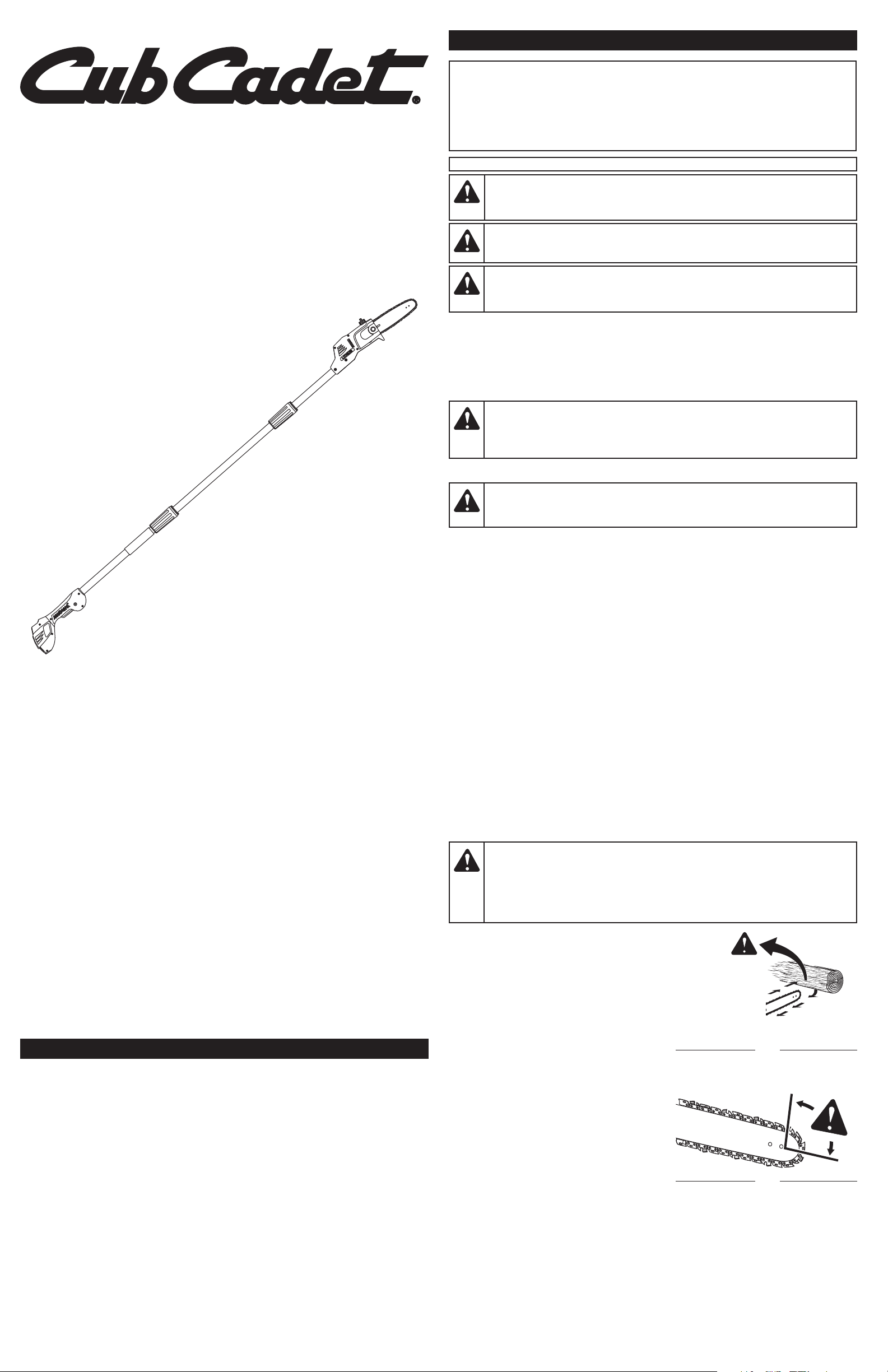
Operator’s Manual
20 Volt Lithium-Ion
Battery-Powered Pole Saw
PS59L
TABLE OF CONTENTS
Service Information . . . . . . . . . . . . . . . . . . . . . . . . . . . . . . . . . . . . . . . . . . . . . . . . . . . . . . . . . . . . . .1
Safety Information . . . . . . . . . . . . . . . . . . . . . . . . . . . . . . . . . . . . . . . . . . . . . . . . . . . . . . . . . . . . . . .1
Know Your Unit . . . . . . . . . . . . . . . . . . . . . . . . . . . . . . . . . . . . . . . . . . . . . . . . . . . . . . . . . . . . . . . . .3
Assembly Instructions . . . . . . . . . . . . . . . . . . . . . . . . . . . . . . . . . . . . . . . . . . . . . . . . . . . . . . . . . . . .3
Starting and Stopping Instructions . . . . . . . . . . . . . . . . . . . . . . . . . . . . . . . . . . . . . . . . . . . . . . . . . .3
Operating Instructions . . . . . . . . . . . . . . . . . . . . . . . . . . . . . . . . . . . . . . . . . . . . . . . . . . . . . . . . . . .3
Maintenance and Repair Instructions . . . . . . . . . . . . . . . . . . . . . . . . . . . . . . . . . . . . . . . . . . . . . . . .4
Cleaning and Storage . . . . . . . . . . . . . . . . . . . . . . . . . . . . . . . . . . . . . . . . . . . . . . . . . . . . . . . . . . . .5
Troubleshooting . . . . . . . . . . . . . . . . . . . . . . . . . . . . . . . . . . . . . . . . . . . . . . . . . . . . . . . . . . . . . . . .5
Specifications . . . . . . . . . . . . . . . . . . . . . . . . . . . . . . . . . . . . . . . . . . . . . . . . . . . . . . . . . . . . . . . . . .5
Warranty Information . . . . . . . . . . . . . . . . . . . . . . . . . . . . . . . . . . . . . . . . . . . . . . . . . . . . . . . . . . .20
DO NOT RETURN THIS UNIT TO THE RETAILER. PROOF OF PURCHASE WILL BE REQUIRED FOR
WARRANTY SERVICE.
For assistance regarding the assembly, controls, operation or maintenance of the unit, please call the
Customer Support Department: 1-877-282-8684 (U.S.) or 1-800-668-1238 (Canada).
Additional information about the unit can be found on our website: www.cubcadet.com (U.S.) or
www.cubcadet.ca (Canada).
Please call the Customer Support Department for replacement parts. When servicing, use only identical
replacement parts.
SAFETY INFORMATION
SAVE THESE INSTRUCTIONS
All information, illustrations and specifications in this manual are based on the latest product information
available at the time of printing. We reserve the right to make changes at any time without notice.
Copyright© 2011 MTD SOUTHWEST INC, All Rights Reserved.
SERVICE INFORMATION
Use 20V Lithium-Ion Battery A59 LBTY (sold separately)
Use 20V Lithium-Ion Battery Charger A59LCHGR (sold separately)
• IMPORTANT SAFETY INSTRUCTIONS •
WARNING:Please read the entire operator’s manual carefully before
attempting to assemble, operate or maintain the unit. Follow all safety instructions. Failure
to do so can result in property damage or serious injury to yourself and/or others.
DANGER:
Kickback may occur when the nose or tip of the guide bar touches an
object, or when the wood closes in and pinches the saw chain in the cut. In some cases, tip contact
may cause a lightening-fast reverse action, kicking the guide bar rapidly back towards the operator.
Pinching the saw chain along the top of the guide bar may push the guide bar rapidly back towards
the operator. Either of these reactions may cause a loss of control over the saw, which could result in
serious injury to the user. Contact with foreign objects within the wood can also induce a loss of chain
saw control.
Fig. 2
Kickback Danger Zone
Fig. 1
Rotational
Kickback
CALIFORNIA PROPOSITION 65
WARNING:Battery posts, terminals and certain finished components contain
lead, lead compounds and chemicals known to the State of California to cause cancer and
birth defects or other reproductive harm. Wash hands after handling.
DANGER:Signals an EXTREME hazard.
Failure to obey a safety DANGER signal WILL result in serious injury or death to yourself or
to others.
WARNING:
Signals a SERIOUS hazard.
Failure to obey a safety WARNING signal CAN result in serious injury to yourself or to others.
CAUTION:
Signals a MODERATE hazard.
Failure to obey a safety CAUTION signal MAY result in property damage or injury to
yourself or to others.
IMPORTANT! Signals special mechanical information.
NOTE: Signals additional important general information.
SYMBOL MEANING
• SAFETY ALERT SYMBOLS •
Safety alert symbols are used to draw your attention to possible dangers. These symbols, and their
explanations, deserve your careful attention and understanding. The safety warnings do not by
themselves eliminate any danger. The instructions or warnings they give are not substitutes for
proper accident prevention measures. These safety instructions are not meant to cover every
possible condition that may occur. If questions arise, please call the Customer Support
Department at 1-877-282-8684 (U.S.) or 1-800-668-1238 (Canada).
Page 2
SAFETY INFORMATION
2
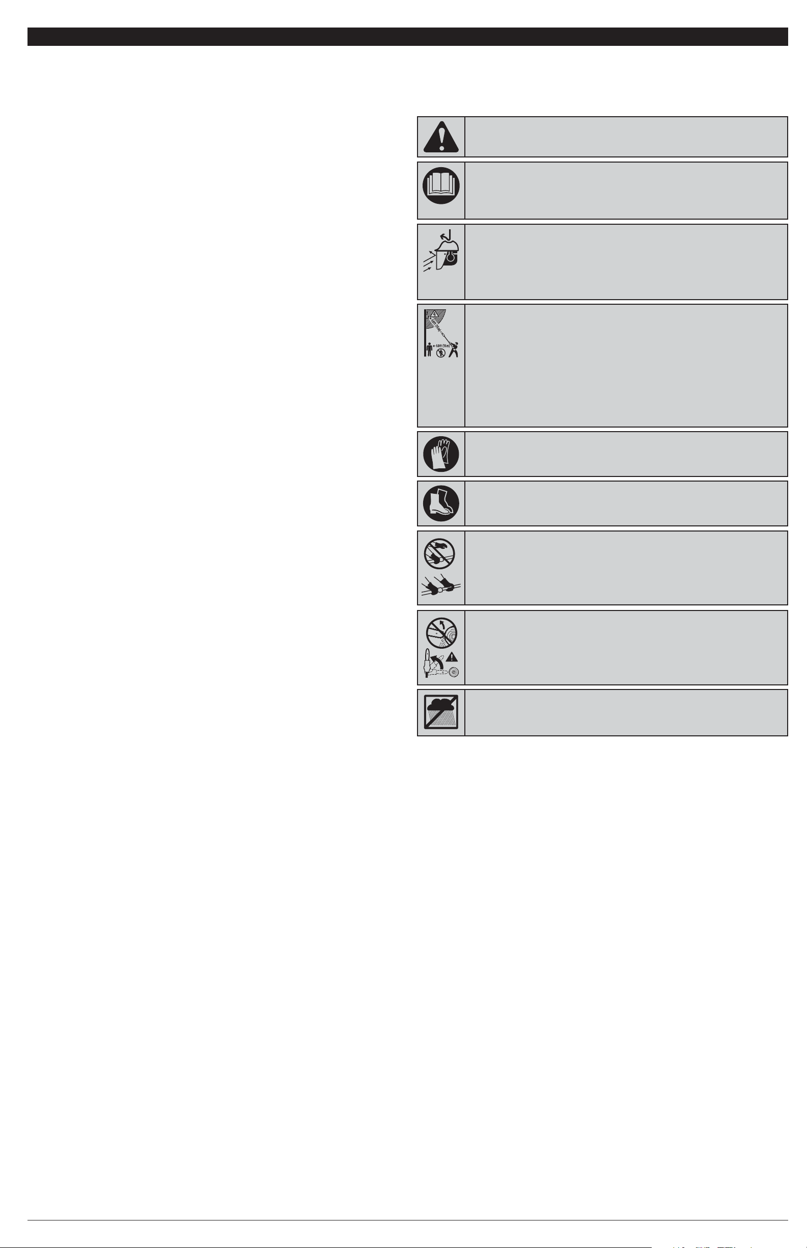
• SAFETY AND INTERNATIONAL SYMBOLS •
This operator's manual describes safety and international symbols and pictographs that
may appear on this product. Read the operator's manual for complete safety, assembly,
operating, maintenance and repair information.
• SAFETY ALERT SYMBOL
Indicates danger, warning or caution. May be used in conjunction with other
symbols or pictographs.
• READ OPERATOR'S MANUAL
WARNING:R
ead the operator’s manual(s) and follow all warnings
and safety instructions. Failure to do so can result in serious injury to the operator
and/or bystanders.
• WEAR HEAD, EYE AND HEARING PROTECTION
WARNING:Thrown objects and loud noise can cause severe eye
injury and hearing loss. Wear eye protection meeting ANSI Z87.1-1989
standards and ear protection when operating this unit. Wear head protection
when operating this unit; falling objects can cause severe head injury. Use a
full face shield when needed.
SYMBOL MEANING
• WEAR SAFETY FOOTWEAR
Wear non-slip safety footwear when using this equipment.
•
WEAR SAFETY GLOVES
Wear non-slip, heavy-duty protective gloves when handling the unit.
• DO NOT USE IN THE RAIN
WARNING:Avoid dangerous environments. Never operate your
unit in the rain, or in damp or wet conditions. Moisture is a shock hazard.
• KICKBACK WARNING
Contact of the guide bar tip with any object should be avoided. Tip contact
may cause the guide bar to move suddenly upward and backward, which
may cause serious injury.
• KEEP BYSTANDERS AWAY
WARNING:Keep all bystanders, especially children and pets, at
least 50 feet (15 m) from the operating area. If anyone enters the work area, stop
the unit!
• POWER LINES CAN CAUSE SEVERE INJURY
WARNING:Do not operate this unit near power lines. Contact
with a power line may cause serious injury or damage to the unit. Maintain a
clearance of at least 50 feet (15 m) between the pole saw (including any
branches it is contacting) and any electrical line.
• If using wedges, only use wedges made of plastic or wood. Do not use metal to hold a cut open.
• Follow the manufacturer’s sharpening and maintenance instructions for the saw chain.
• Use only replacement bars and chains specified by the manufacturer or the equivalent.
• Use devices, such as low-kickback chains, guide bar nose guards, chain brakes and special guide bars,
which reduce the risks associated with kickback. There are no other replacement components for
achieving kickback protection in accordance with CSA Z62.3.
•
Low-kickback saw chain is chain that has met the kickback performance requirements of ANSI B175.1-1991
and is in accordance with CSA Z62.3. Do not use other replacement chain unless it has met these
requirements for the specific model. As saw chains are sharpened, some of the low kickback qualities are
lost and extra caution should be used.
OTHER SAFETY PRECAUTIONS
• DO NOT operate the unit with one hand! Serious injury to the operator, helpers or bystanders may result
from one-handed operation. This unit is intended for two-handed use.
• DO NOT handle the unit with wet hands.
• DO NOT
operate a
pole
saw in a tree or on a ladder unless specifically trained to do so.
• DO NOT expose the unit to rain. Do not use the unit in damp or wet locations or conditions.
• DO NOT
operate the unit on wet surfaces.
• DO NOT use the unit in the presence of flammable liquids or gases.
• DO NOT operate a unit that is damaged, improperly adjusted or not completely and securely assembled.
Be sure that the unit stops when the trigger is released. Do not use the unit if the switch does not turn the
unit on and off properly or if the switch lock does not work.
• DO NOT attempt operations beyond the operator’s capacity or experience.
• DO NOT cut near electrical cables or power lines.
• DO NOT force the pole saw, especially near the end of a cut. It will do a better, safer job when used at
the intended rate.
• To reduce the risk of electric shock, avoid body contact with grounded conductors, such as metal pipes
or wire fences.
• Keep all body parts away from the saw chain when the motor is operating. Before starting the saw, make
sure the saw chain is not contacting anything.
• Always stop the motor when operation is delayed, before setting down the unit or when walking from one
location to another. Make sure the chain comes to a complete stop.
•
To avoid accidental starting, never carry the unit with fingers on the switch trigger.
•
Always carry the pole saw with the battery removed, finger off the switch trigger and the guide bar and saw
chain sheathed in the scabbard and positioned to the rear.
•
Always make sure the lock-off button is in the locked or OFF position before installing or removing the battery.
• Cut wood only. Do not use the pole saw for purposes for which it was not intended.
•
When cutting a limb that is under tension, be alert for spring back, which may cause the operator to
be struck when the tension of the wood fibers is released.
• Use extreme caution when cutting small-sized brush and saplings, as slender material may catch the
saw chain and be whipped toward the operator or pull the operator off balance.
•
This unit is intended for infrequent use by homeowners, cottagers and campers, and for general
applications such as limbing, pruning, etc. It is not intended for prolonged use. If the intended use
involves prolonged periods of operation, this may cause circulatory problems in the user’s hands due
to vibration. It may be appropriate to use a saw having an anti-vibration feature.
MAINTENANCE AND STORAGE SAFETY
• DO NOT perform
maintenance
procedures other than those described in this manual. Do not
attempt to repair; there are no user serviceable parts inside.
• Follow all maintenance instructions in this manual.
• Before inspecting, servicing, cleaning, storing, transporting or replacing any parts on the unit:
1.
Make sure all moving parts have stopped.
2. Allow the unit to cool.
3. Make sure the lock-off button is in the locked or OFF position.
4. Remove the battery.
• Never remove, modify or make inoperative any safety device furnished with the unit.
• For safer, more effective performance, make sure the bar and chain are properly cleaned, lubricated,
tightened and sharpened. Check the bar and chain at frequent intervals for proper adjustment.
• Frequently inspect the unit for damage.
Before further use, any damaged part should be carefully checked
to determine that it will operate properly and perform its intended function. Check for alignment of moving
parts, binding of moving parts, breakage of parts and any other conditions that may affect its operation.
Damaged parts should be properly repaired or replaced.
• Use only original manufacturer replacement parts and accessories, which are designed specifically to
enhance the performance and maximize the safe operation of the product. Failure to do so may cause
poor performance and possible injury. Use only the chain and guide bar supplied with this product.
• Remove the battery from the unit when not in use.
• Be sure to secure the unit while transporting.
• Always use the scabbard on the bar and chain during transportation and storage.
• When not in use, store the unit in a locked-up and dry, or high and dry, place to prevent unauthorized use
or damage. Keep out of the reach of children.
• Keep the handle and grip dry, clean and free from debris, oil and grease. Clean the unit after each use.
Never douse or squirt the unit with water or any other liquid. Do not use solvents or strong detergents.
• If dropped in water, do not use the unit.
• USE BOTH HANDS
Always use both hands while operating the pole saw. Never use only one
hand to operate the unit.
SAVE THESE INSTRUCTIONS
Page 3
This unit requires assembly. The saw chain may be loose on the guide bar; refer to Adjusting the Chain Tension in the Maintenance and
Repair Instructions section.
UNPACKING
• Carefully remove the product and any accessories from the box.
• Inspect the product carefully to make sure no breakage or damage occurred during shipping.
• Do not discard the packing material until you have carefully inspected and satisfactorily operated the product.
• If any parts are damaged or missing, please call 1-877-282-8684
(U.S.) or 1-800-668-1238 (Canada) for assistance.
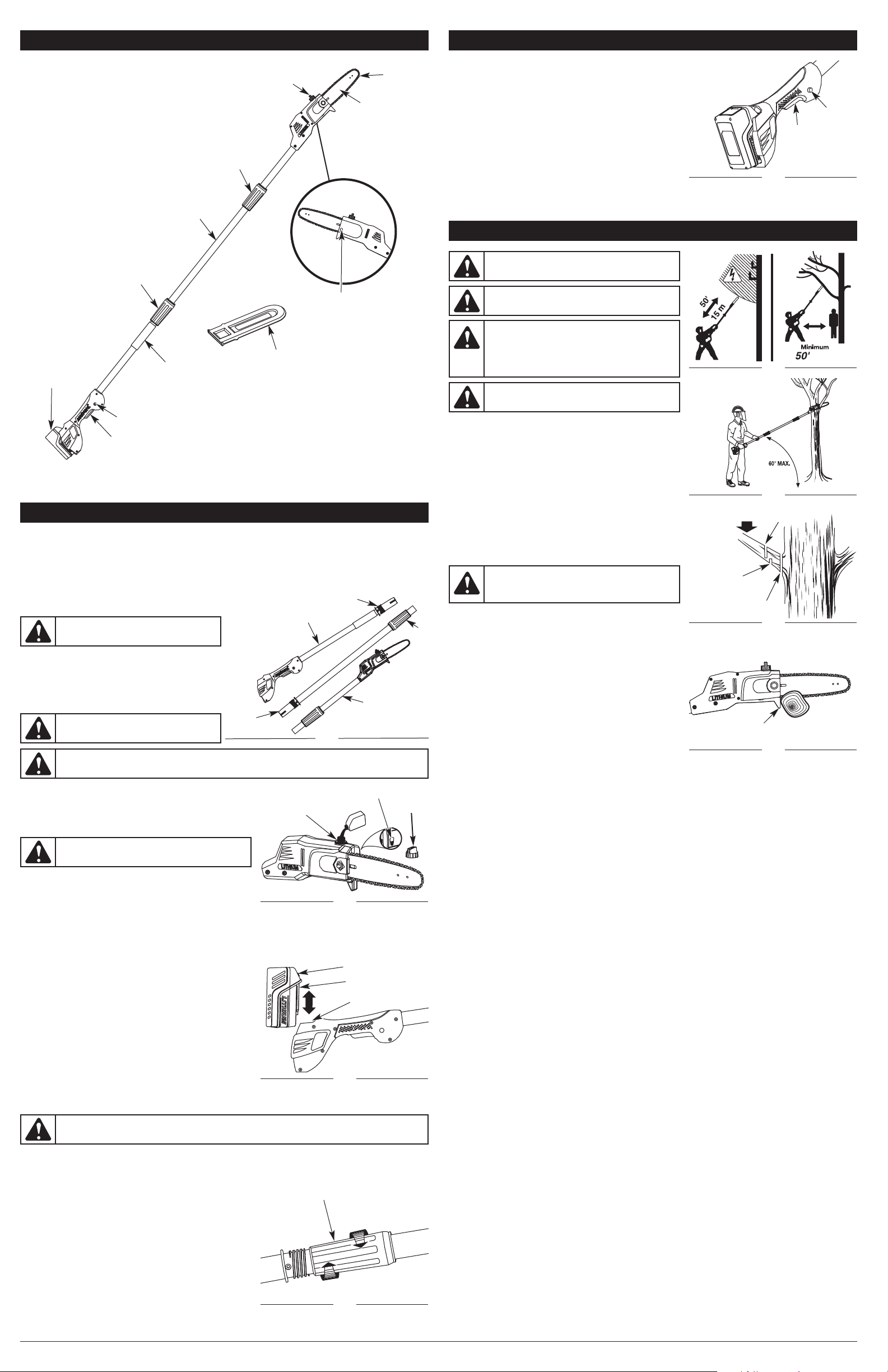
ASSEMBLING THE POLES
There should be three poles (Fig. 3).
1. Insert the extension pole into the handle pole and slide them
together. The tubes are egg-shaped and will only install one way.
2. Lower the collar on the extension pole to the threaded base on the
handle pole and rotate the collar to the right to tighten (Fig. 6).
3. Repeat this process to attach the extension pole to the
powerhead pole.
ADDING BAR AND CHAIN LUBRICANT
Only use bar and chain oil that is formulated to perform over a wide range of
temperatures with no diluting required in the oil reservoir. Do not use motor oil or
any other petroleum-based oil.
NOTE: This pole saw comes from the factory with the bar lube reservoir empty. Use
the bottle of bar and chain oil that is included with the unit.
1. Remove the bar lube reservoir cap (Fig. 4).
2. Carefully pour the bar and chain oil into the bar lube reservoir.
3. Replace the oil cap and tighten securely.
4. Wipe off excess oil.
5. The unit is ready for use.
NOTE: Because bar lube reservoirs are designed to keep oil slowly flowing onto the chain, be sure to check the oil level after every 15
minutes of operation and refill the bar lube reservoir as needed.
NOTE: Do not use dirty, used or otherwise contaminated oils. Damage may occur to the guide bar or chain.
IMPORTANT! Please dispose of oil properly. Consult your local waste authority for information regarding available disposal options.
INSTALLING AND REMOVING THE BATTERY
Follow these instructions in order to avoid injury and to reduce the risk of electric
shock or fire:
• Verify that the lock-off button is in the locked or OFF position before installing
or removing the battery. Refer to Starting and Stopping Instructions.
• Verify that the battery is removed and the lock-off button is in the locked or
OFF position before inspecting, adjusting or performing maintenance on any
part of the unit.
Installing the Battery
1. Align the tongue of the battery with the handle cavity (Fig. 5).
2. Grasp the pole saw firmly.
3. Push the battery into the handle cavity until the latch locks into place.
4.
Do not use force when inserting the battery. It should slide into position and “click.”
Removing the Battery
1. Press the latch button on the battery down and hold (Fig. 5).
2. Grasp the pole saw firmly and pull the battery out of the handle cavity.
NOTE: The battery fits into the handle cavity snugly in order to prevent accidental dislodging. It may require a strong pull to remove it.
IMPORTANT! The battery is equipped with an internal circuit breaker that will automatically shut off power to the unit if the battery is
overloaded during heavy use. Once cooled, the battery will reset itself. Follow these steps if an overload occurs:
1. Release the switch trigger and then restart the unit. Refer to Starting and Stopping Instructions.
2. The battery may need to be removed for approximately 1 minute, allowed to cool and then reinstalled.
ADJUSTING THE POLE LENGTH
1. Remove the battery from the handle cavity (Fig. 5).
2. Rotate the collar(s) to the left to loosen (Fig. 6).
3. Remove the extension pole to shorten the pole, or add the extension pole to
lengthen the pole.
4. When the desired length is achieved, rotate the collar to the right to tighten.
NOTE: Extend the pole only to the length required to reach the limb being cut.
NOTE: Adjust hand placement on the shaft of the pole saw to keep proper
balance. Do not attempt to use the pole saw at a length that does not allow
for proper footing and balance at all times.
3
KNOW YOUR UNIT
ASSEMBLY INSTRUCTIONS
Scabbard
Lock-off Button
Extension Pole
Quick-view Oil Indicator
Powerhead Pole
Handle Pole
Threaded Base
Collar
Extension
Pole
Fig. 3
APPLICATIONS
This unit may be used for the purposes listed below:
• Cutting Small Limbs
• General Tree Pruning
Bar Lube
Reservoir Cap
Collar
Collar
Battery
(Sold Separately)
WARNING:
Do not install the battery until the
assembly is complete. Failure to comply could result in
accidental starting and possible serious personal injury.
WARNING:
Failure to lock the powerhead pole
as directed could result in serious injury or death.
WARNING:
Do not use any attachments or accessories not recommended by the manufacturer of this product. The
use of attachments or accessories not recommended can result in serious personal injury.
Bar Lube
Reservoir
Fig. 4
Quick View Oil Indicator
Bar Lube
Reservoir
Cap
WARNING:
Make sure the bar lube reservoir is always
filled. Failure to fill the bar lube reservoir will cause irreparable
damage to the unit.
Latch Button
Fig. 5
Tongue
Handle Cavity
Loosen
Fig. 6
Collar
Tighten
OPERATING INSTRUCTIONS
STARTING AND STOPPING INSTRUCTIONS
STARTING THE MOTOR
To help prevent accidental start-ups, this unit has a lock-off button and a switch
trigger that must be used together to start the unit.
1. Fit the battery into the handle cavity (Fig. 5). Refer to Installing the Battery.
2. Place your thumb on the lock-off button and push it completely in (Fig. 7).
3. While holding the lock-off button in, press and hold the switch trigger.
4. Release the lock-off button and continue to squeeze the switch trigger for
continued operation.
STOPPING THE MOTOR
1. Release the switch trigger.
NOTE: It is normal for the chain to coast to a stop once the switch trigger is released.
NOTE: Upon release of the switch trigger, the lock-off button will automatically reset
to the locked position.
PREPARATION FOR CUTTING
• To prevent electrocution, do not operate within 50 feet (15 m) of overhead
electrical lines (Fig. 8).
• Keep everyone – helpers, bystanders, children and animals – at least 50 feet
(15 m) away from the work area (Fig. 8). If anyone enters the work area, stop
the unit!
• Wear non-slip gloves for maximum grip and protection.
• Be certain the collars are fully tightened before operating the unit; check them
periodically for tightness during use to avoid serious injury.
• Maintain a proper grip on the unit whenever the motor is running. Hold the
unit firmly with both hands. Firmly grip the handle with the right hand and the
pole shaft with the left hand (Fig. 9).
• The operator should be to the left of the chain line. Never use a left-handed
(cross-handed) grip, or any stance that places any body part across the chain
line (Fig. 9).
• Never stand directly under the limb being cut.
PRUNING
This unit is designed for trimming small branches and limbs up to 6 inches (15.2 cm)
in diameter. For best results, observe the following precautions.
• Do not use the pole saw for cutting down trees.
• Plan the cut carefully. Be aware of the direction in which the branch will fall.
• Branches may fall in unexpected directions. Do not stand directly under the
branch being cut (Fig. 9).
• The most typical cutting application is to position the unit at an angle of 60°
or less, depending on the specific situation (Fig. 9). As the angle of the pole
saw shaft to the ground increases, the difficulty of making the first cut (from
the underside of the limb) increases.
• Remove long branches in several stages.
• Cut lower branches first to allow the top branches more room to fall.
• Work slowly, keeping both hands on the unit with a firm grip. Maintain secure
footing and balance
• Do not cut from a ladder; this is extremely dangerous. Leave this operation for
professionals.
• Do not make the flush cut next to the main limb or trunk until the limb has
been cut further out to reduce the weight.
BASIC CUTTING PROCEDURE
Follow the steps below to prevent stripping the bark from the main member of the tree or shrub. Do not use a back-and-forth sawing motion.
1. Make a shallow first cut (1/4 of the limb’s diameter) on the underside of the limb close to the main limb or trunk (Fig. 10).
2. Make a second cut from the top side of the limb outboard from the first cut. Continue the cut through the limb until the limb separates
from the tree. Be prepared to balance the weight of the tool when the limb falls.
3. Make a final cut close to main limb or trunk.
NOTE: For second and final cuts (from the top of the limb or branch), hold the front cutting guide against the limb being cut (Fig. 11). This will
help steady the limb and make it easier to cut. Allow the chain to do the cutting; only exert light downward pressure. If the cut is forced,
damage to the bar, chain or motor may result.
4. Release the trigger as soon as the cut is completed. Failure to follow proper cutting procedures will result in the bar and chain binding
and becoming pinched or trapped in the limb. If this should happen:
• Stop the motor and remove the battery from the pole saw.
• If the limb can be reached from the ground, lift the limb while holding the saw. This should release the “pinch” and free the saw.
• If the saw is still trapped, call a professional for assistance.
WARNING:
If any parts are damaged or missing, do not
operate the unit until the parts are replaced. Failure to heed this
warning could result in serious personal injury.
Switch
Trigger
Fig. 7
Lock-off
Button
Load
Fig. 10
Second Cut
Cutting
Guide
Fig. 11
Fig. 9
Fig. 8
First Cut
1/4 Diameter
Final Cut
WARNING:
Do not allow familiarity with this unit to
promote carelessness. Remember that a careless fraction of a
second is enough to inflict serious injury.
Switch Trigger
Guide Bar
Chain
CAUTION:
When the battery is not installed in the unit, keep it away from paper clips, coins, keys, nails, screws or
other metal objects that could make a connection from one terminal to another. Shorting the battery terminals together
may cause sparks, burns or a fire.
WARNING:
Always wear appropriate eye and ear
protection when operating this unit. Wear safety goggles, or
safety glasses with side shields, that are marked as meeting
ANSI Z87.1-1989 standards. Failure to do so could result in
serious eye injury caused by thrown objects. If the operation is
dusty, wear a face mask or dust mask. When operating the unit
over the head, use a hardhat or other type of safety helmet.
Foam Grip
WARNING:
Use caution when pruning heavy branches.
Falling branches can cause serious injury. Always wear head
protection, plan a safe exit from the path of falling limbs and
stay alert.
WARNING:
Wear non-slip gloves for maximum grip and
protection. Refer to the Safety Information section for
appropriate safety equipment.
NO TOOLS REQUIRED!
(15 m)
Page 4
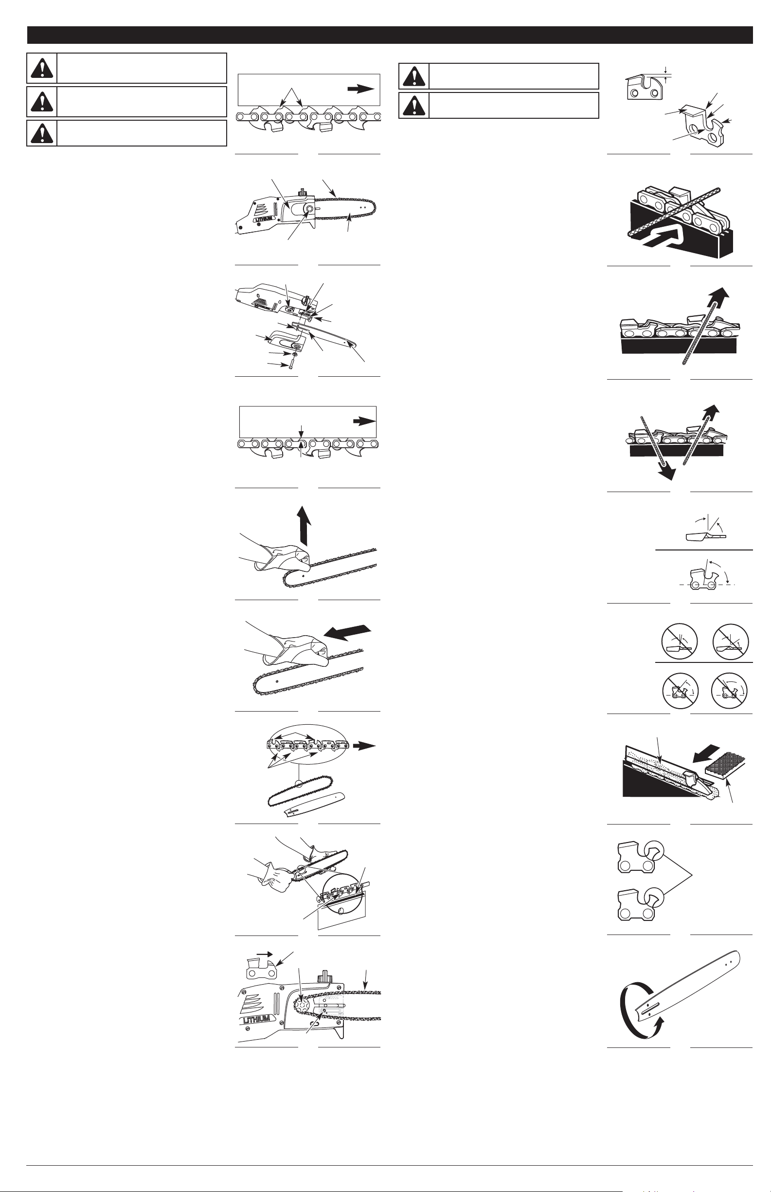
CHAIN MAINTENANCE
For smooth and fast cutting, the chain needs to be maintained properly. The
following conditions indicate that the chain requires sharpening:
• Wood chips are small and powdery.
• The chain must be forced through the wood during cutting.
• The chain cuts to one side.
During maintenance of the chain, consider the following:
• The depth gauge (or raker clearance) setting determines the height at which the
cutter enters the wood and the size of the wood chip that is removed (Fig. 21).
Too much clearance increases the potential for kickback. Too little clearance
decreases the size of the wood chip, thus decreasing the chain's cutting ability.
• If the cutter teeth have hit hard objects, such as nails and stones, or were
abraded by mud or sand on the wood, have a service dealer sharpen the chain.
NOTE: Inspect the drive sprocket for wear or damage when replacing the chain.
If signs of wear or damage are present, do not use the unit.
NOTE: If you do not fully understand the correct procedure for sharpening the
cutters after reading the instructions that follow, have the saw chain
sharpened by an authorized service center or replace the chain with a
recommended low-kickback chain.
SHARPENING THE CUTTERS
Be careful to file all cutters to the specified angles and to the same length. Fast
cutting can be obtained only when all cutters are uniform.
• Tighten the chain tension enough so that the chain does not wobble. Do all of
the filing at the midpoint of the guide bar. Wear gloves for protection.
• Use a round file and holder.
• Keep the file level with the top plate of the tooth (Fig. 22). Do not let the file
dip or rock.
• Using light but firm pressure, stroke towards the front corner of the tooth (Fig. 23).
Lift the file away from the cutter before returning the file to the beginning of the
sharpening stroke.
• Put a few firm strokes on every tooth. File all left hand cutters in one direction
(Fig. 24). Then move to the other side and file the right hand cutters in the
opposite direction. Occasionally remove filings from the file with a wire brush.
Top Plate Filing Angle
• CORRECT (30°) – File holders are marked with guide marks to align the file
properly and produce the correct top plate angle (Fig. 25).
• INCORRECT (LESS THAN 30°) – For cross cutting (Fig. 26).
• INCORRECT (MORE THAN 30°) – This creates a feathered edge that dulls quickly.
Side Plate Filing Angle
• CORRECT (80°) – This is produced automatically if the correct diameter file is
used in the file holder (Fig. 25).
• INCORRECT (HOOK) – This causes the chain to “grab” and dull quickly,
increasing the potential for kickback. A hook is caused by using a file with too
small a diameter or a file held too low (Fig. 26).
• INCORRECT (BACKWARD SLOPE) – This causes a need for too much feed
pressure, producing excessive wear to the bar and chain. A backward slope
is caused by using a file with too large a diameter or a file held too high.
MAINTAINING DEPTH GAUGE CLEARANCE
• Maintain the depth gauge at a clearance of 1/32 inch (0.6 mm) (Fig. 21). Use a
depth gauge tool for checking the depth gauge clearances.
• Every time the chain is filed, check the depth gauge clearance.
• Use a flat file and a depth gauge jointer to lower all gauges uniformly (Fig. 27).
Use a 1/32 inch (0.6 mm) depth gauge jointer. After lowering each depth
gauge, restore the original shape by rounding the front (Fig. 28). Be careful
not to damage adjoining drive links with the edge of the file.
• Depth gauges must be adjusted with the flat file in the same direction the
adjoining cutter was filed with the round file.
• Use care not to contact the cutter face with the flat file when adjusting depth
gauges.
MAINTAINING THE GUIDE BAR
After every week of use, rotate the guide bar on the saw to distribute the wear for
maximum guide bar life (Fig. 29). Frequently check the guide bar for damage.
Feathering and burring of the guide bar rails (the ridges on either side of the bar
groove) is a normal process of guide bar wear. Such faults should be smoothed
with a file as soon as they occur.
A guide bar with the following faults should be replaced:
• Wear inside the guide bar rails that permits the chain to lay sideways.
• Bent guide bar.
• Cracked or broken rails.
• Spread rails.
4
ADJUSTING THE CHAIN TENSION
The chain must be tensioned whenever the flats on the drive links hang out of the
bar groove (Fig. 12). Check for proper chain tension before starting the unit and
periodically during operation.
NOTE: A new chain tends to stretch. Check the chain tension frequently and
tighten as required.
1. Stop the motor, make sure the lock-off button is in the locked or OFF
position and remove the battery from the unit. Refer to Removing the Battery
in the Assembly Instructions section.
2. Slightly loosen the bar cover bolt (Fig. 13).
3. Rotate the chain-tensioning bolt (Fig. 14) clockwise with a hex wrench (Allen
wrench) to tension the chain. The desired tension depends on the
temperature of the chain:
• Cold Chain Tensioning - A cold chain is correctly tensioned when there is
no sag on the underside of the guide bar and the chain seats snugly
against the guide bar with the drive links in the bar groove.
• Warm Chain Tensioning - During normal operation, the temperature of the
chain will increase. The drive links of a correctly tensioned warm chain will
hang approximately 1/16 inch (1.3 mm) out of the bar groove (Fig. 15).
4. Once adjusted, lift the tip of the guide bar up to check for proper tension
(Fig. 16). If the chain is still too loose, release the tip of the guide bar and turn
the chain-tensioning bolt 1/2 turn clockwise. Repeat this process until the
desired tension is achieved.
NOTE: If the chain is too tight, it will not rotate. To loosen the chain, turn the
chain-tensioning bolt 1/4 turn counterclockwise. Ensure that the chain can be
turned by hand without binding (Fig. 17).
5. Hold the tip of the guide bar up and rotate the bar cover bolt clockwise to secure.
REMOVING/REPLACING THE GUIDE BAR AND CHAIN
Use only a low-kickback chain on this saw. This fast-cutting chain provides
kickback reduction when properly maintained.
NOTE: When replacing the guide bar and chain, use only manufacturer
suggested replacement parts. The use of any other parts may create a hazard
or cause product damage and will VOID the warranty.
Removing the Old Guide Bar and Chain
1. Make sure the lock-off button is in the locked or OFF position and remove
the battery from the unit.
2. Rotate the bar cover bolt counterclockwise and remove the bar cover bolt,
sleeve and bar cover (Fig. 14).
3. Remove the guide bar and chain from the mounting surface.
4. Remove the old chain from the guide bar.
Installing the New Guide Bar and Chain
1. Lay out the new saw chain in a loop and straighten any kinks. The cutters on
the top of the guide bar should face toward the guide bar tip in the direction
of chain rotation (Fig. 18). If they face backward, turn the loop over.
2. Place the chain drive links into the bar groove as shown (Fig. 19).
NOTE: Make sure the chain is correctly installed and the cutters are facing in the
correct direction (Fig. 18).
3. Position the chain so there is a loop at the back of the guide bar.
4. Hold the chain in position on the guide bar and place the loop around the
drive sprocket.
5. Fit the guide bar flush against the mounting surface so that the bar stud is in
the
bar stud slot
.
NOTE: When placing the guide bar on the bar stud, ensure that the chain-
tensioning pin is in the chain tension pin hole (Fig. 20).
6. Replace the bar cover, sleeve and bar cover bolt. To tighten, rotate the bar
cover bolt clockwise with a hex wrench (Allen wrench).
NOTE: Tighten the bar cover bolt to finger tightness only. The guide bar should
still be free to move for chain tension adjustment.
7. Adjust the chain tension. Refer to the Adjusting the Chain Tension
instructions above.
MAINTENANCE AND REPAIR INSTRUCTIONS
Chain Rotation
Fig. 20
Drive Sprocket
Chain
WARNING:
A dull or improperly sharpened chain can
cause excessive motor speed during cutting, which may result
in severe motor damage.
WARNING:
Improper chain sharpening increases the
potential of kickback. Failure to replace or repair a damaged
chain can cause serious injury.
Top Plate
Fig. 21
Cutting Corner
Gullet
Fig. 22
Fig. 23
Left Hand
Cutters
Fig. 24
Right Hand
Cutters
Chain Tensioning Pin
Depth
Gauge
Raker Clearance
1/32” (0.6 mm)
Side Plate
Fig. 27
Fig. 28
Fig. 29
Flat File
Depth Gauge Jointer
Restore Original
Shape by Rounding
the Front
Filing Height
Filing Angle
Fig. 25
Fig. 26
Top Plate
Less than 30˚
More than 30˚
30˚
Incorrect
Filing Angles
Hook
Backward Slope
80˚
Correct
Filing Angles
Top Plate
Side Plate
Side Plate
Fig. 18
Chain Drive
Links
Chain
Rotation
Cutters
Approx. 1/16”
(1.3 mm)
Fig. 15
Bar Tip
WARNING:
Before inspecting, cleaning or servicing the
unit, stop the motor, wait for all moving parts to stop and
remove the battery. Failure to follow these instructions can
result in serious personal injury or property damage.
Flats
Fig. 12
Bar Cover Bolt
Fig. 13
WARNING:
To avoid possible serious injury, never touch or
adjust the chain while the motor is running. The saw chain is
very sharp; always wear protective gloves when performing
maintenance on the chain.
CAUTION:
A chain tensioned while warm, may be too tight
upon cooling. Check the “cold tension” before the next use.
Bar Tip
Drive Sprocket
Fig. 14
Chain-tensioning
Pin
Bar Stud
Bar Cover
Chain
Guide Bar
Bar Stud Slot
Bar Groove
Bar Cover
Bolt
Bar
Cover
Chain-tensioning
Pin Hole
Chain-tensioning
Bolt
Sleeve
Fig. 19
Fig. 16
Fig. 17
Bar Groove
Chain Drive
Links
Page 5

CAUSE SOLUTION
The battery lacks sufficient charge Charge the battery
5
CLEANING INSTRUCTIONS
NOTE: It is normal for oil to seep from the unit when it is not in use. Please take this into consideration when storing the unit.
• Remove the battery from the unit.
• Slacken the chain if it was retensioned at operating temperature during cutting work. The chain contracts as it cools down. If it is not
slackened, it may damage the gearbox and bearings.
• Wipe the unit down with a damp cloth. Do not douse the unit with water. Do not use solvents or strong detergents. If preparing the unit
for long-term storage (three months or more), remove the chain and guide bar, then clean the unit thoroughly with a damp cloth. A firmbristled, non-wire, brush can be used to remove debris from the bar groove and assembly. When finished, reassemble the unit. Refer to
Removing/Replacing the Guide Bar and Chain.
• Spray the guide bar and chain with corrosion inhibiting oil.
STORAGE INSTRUCTIONS
• Follow the Cleaning Instructions listed above.
• Attach the scabbard to the guide bar and chain.
• Store the unit in a dry, high and/or locked location, out of the reach of children and other unauthorized persons.
WARNING:
Do not let brake fluids, gasoline, petroleum-based products, penetrating oils, etc., come in contact with plastic
parts. These chemicals may damage, weaken and destroy plastic, which may result in serious personal injury.
SPECIFICATIONS*
* All specifications are based on the latest product information available at the time of printing. We reserve the right to make changes at
any time without notice.
Type . . . . . . . . . . . . . . . . . . . . . . . . . . . . . . . . . . . . . . . . . . . . . . . . . . . . . . . . . . . . . . . . . . . . . . . . . . . . . . . . . . . . . Cordless, Battery-powered
Motor. . . . . . . . . . . . . . . . . . . . . . . . . . . . . . . . . . . . . . . . . . . . . . . . . . . . . . . . . . . . . . . . . . . . . . . . . . . . . . . . . . . . . . . . . . . . . . . . . . . . . . . 20 V
Motor Speed. . . . . . . . . . . . . . . . . . . . . . . . . . . . . . . . . . . . . . . . . . . . . . . . . . . . . . . . . . . . . . . . . . . . . . . . . . . . . . . . . . . . . . . . . . . . . 3000 rpm
Bar Length . . . . . . . . . . . . . . . . . . . . . . . . . . . . . . . . . . . . . . . . . . . . . . . . . . . . . . . . . . . . . . . . . . . . . . . . . . . . . . . . . . . . . . . 8 inches (20.3 cm)
Chain Pitch. . . . . . . . . . . . . . . . . . . . . . . . . . . . . . . . . . . . . . . . . . . . . . . . . . . . . . . . . . . . . . . . . . . . . . . . . . . . . . . . . . . . . . . . 3/8 inch (9.5 mm)
Chain Type. . . . . . . . . . . . . . . . . . . . . . . . . . . . . . . . . . . . . . . . . . . . . . . . . . . . . . . . . . . . . . . . . . . . . . . . . . . . . . . . . . . . . . . . . . . . 8-inch Chain
Guide Bar Type . . . . . . . . . . . . . . . . . . . . . . . . . . . . . . . . . . . . . . . . . . . . . . . . . . . . . . . . . . . . . . . . . . . . . . . . . . . . . . . . . . . . . . . . . . 8-inch Bar
Chain speed. . . . . . . . . . . . . . . . . . . . . . . . . . . . . . . . . . . . . . . . . . . . . . . . . . . . . . . . . . . . . . . . . . . . . . . . . . . . . . . . . . . . . . . 19.68 ft./s (6 m/s)
Bar Lube Reservoir Capacity . . . . . . . . . . . . . . . . . . . . . . . . . . . . . . . . . . . . . . . . . . . . . . . . . . . . . . . . . . . . . . . . . . . . . . . . . . . . . 1.5 oz (45 ml)
Weight (with Battery) . . . . . . . . . . . . . . . . . . . . . . . . . . . . . . . . . . . . . . . . . . . . . . . . . . . . . . . . . . . . . . . . . . . . . . . . . . . . . . . . . . . . . 11 lb (5 kg)
CLEANING AND STORAGE
The chain is dull Sharpen the chain
The chain is on backwards Reverse the direction of the chain
TROUBLESHOOTING
NOTE: For maintenance beyond the minor adjustments listed above, or for replacement parts, please call the Customer Support
Department at 1-877-282-8684 (U.S.) or 1-800-668-1238 (Canada).
The chain tension is too tight Adjust the chain tension
The bar lube reservoir is empty Refill the bar lube reservoir
The chain tension is too tight Adjust the chain tension
The guide bar and chain are assembled incorrectly Refer to Removing/Replacing the Guide Bar and Chain
The guide bar and chain are damaged Inspect the guide bar and chain for damage
The drive assembly is damaged Refer to Service Information
THE CHAIN DOES NOT ROTATE WHILE THE MOTOR IS RUNNING
THE CHAIN ROTATES, BUT DOES NOT CUT
ACCESSORIES (SOLD SEPARATELY)
Model #
A59 LBTY . . . . . . . . . . . . .
A59LCHGR . . . . . . . . . . . .
Description
20V Lithium-ion Battery
20V Lithium-ion Battery Charger
Part #
753-06579 . . . . . . .
753-06580 . . . . . . .
THE MOTOR OPERATES SLOWLY OR WILL NOT OPERATE
NOTES
REPLACEMENT PARTS
Description
8-inch Chain
8-inch Bar
Part #
753-06628. . . . . . . . . . . . . . . . . . . . . . . . . . . . . . . . . . . . . .
753-06630. . . . . . . . . . . . . . . . . . . . . . . . . . . . . . . . . . . . . .
THE BAR AND CHAIN ARE RUNNING HOT AND SMOKING OR STUCK
Page 6

6
NOTES
Page 7

LIRE TOUTES LES INSTRUCTIONS AVANT UTILISATION
PRÉCAUTIONS DE SECURITÉ ÉLEMENTAIRES
• Lisez attentivement et assurez-vous de bien comprendre le manuel de l’utilisateur de la batterie qui
alimente cet appareil.
• Familiarisez-vous avec les commandes et la marche à suivre pour une utilisation correcte de cet appareil.
Apprenez à rapidement couper le moteur de l’appareil et à mettre les commandes en position neutre.
• Restez attentif. N’utilisez pas cet appareil lorsque vous êtes fatigué, malade, ou sous l’influence de
l’alcool, de drogues, ou de médicaments.
• Ne laissez jamais les enfants utiliser cet appareil. Ne laissez jamais des adultes utiliser cet appareil
sans qu’ils aient reçu une formation appropriée.
• Ne pas laisser l'unité à être utilisé comme un jouet.
• Assurez-vous que toutes les protections et tous les dispositifs de sécurité ont été correctement
installés avant d’utiliser l’appareil.
• Conservez ces instructions. Consultez-les régulièrement et utilisez-les pour donner des consignes
aux autres utilisateurs. Si vous prêtez cet appareil à quelqu’un, prêtez-lui également ces instructions.
PRÉCAUTIONS DE SECURITÉ AVANT L’UTILISATION
• NE vous fiez PAS exclusivement aux protections de sécurité incorporées dans l’appareil.
• Faites reculer les personnes se trouvant à proximité, en particulier les enfants et les animaux, d’au
moins 50 pieds (15 m). Si quelqu’un s’approche de la zone de travail, arrêtez l’appareil !
• Veillez à ce que la zone de travail soit dégagée. Les zones encombrées favorisent les accidents. Ne
commencez pas à couper avant d’avoir nettoyé la zone de tous débris, d’avoir une position parfaitement
stable, et de vous être assuré qu’il y a suffisamment d’espace pour reculer en cas de chute de branches.
• Portez toujours des protections oculaires et auditives lorsque vous utilisez cet appareil. Portez des
lunettes de sécurité ou une visière dotée de protections latérales conformes aux normes ANSI
Z87.1-1989. Le non-port de ces protections peut entraîner de graves lésions oculaires suite à la
projection ou la chute d’objets. Si la tâche est poussiéreuse, portez un masque anti-poussière.
Lorsque vous utilisez l'appareil au delà de votre tête, portez un casque de sécurité.
• Habillez-vous de manière adéquate, portez de vêtements épais et près du corps (pantalon et
chemise à manches longues), des gants et des bottes de travail antidérapants. Ne portez pas de
vêtements amples, de bijoux, de pantalons courts, de sandales et ne soyez pas pieds nus.
Attachez-vous les cheveux au dessus du niveau des épaules pour éviter qu’ils ne se prennent dans
les parties en mouvement de l’appareil.
• Utilisez l’appareil uniquement à la lumière du jour ou sous un éclairage artificiel satisfaisant.
• N’utilisez pas cet appareil pour des fonctions pour lesquelles il n’a pas été prévu.
COMPRENDRE L’EFFET DE REBOND
•Un rebond rotatif peut se produire lorsque la partie
supérieure de la pointe du guide heurte un objet alors
que la chaîne est en mouvement (Fig. 1 & 2). La
chaîne peut en conséquence s’enfoncer dans l'objet
et s’arrêter momentanément de tourner. Le guide est
alors propulsé vers le haut à toute vitesse et se
retourne vers l'utilisateur dans un mouvement inverse
ultra-rapide.
•Un effet de rebond par coincement peut se
produire lorsque le bois se referme de chaque côté
d'une coupe et coince la chaîne en mouvement au
niveau du haut du guide. Ceci peut caler la chaîne
net. La force de la chaîne est ainsi renversée, ce qui
provoque un retour instantané et soudain de la
tronçonneuse vers l’utilisateur.
•Un effet de calage peut se produire lorsque la chaîne
en mouvement sur la partie inférieure du guide heurte
un objet étranger dans le bois. Ceci peut caler la
chaîne net. La tronçonneuse est alors propulsée en
avant et s’écarte de l’utilisateur, qui pourrait
potentiellement en perdre le contrôle.
PRÉCAUTIONS DE SECURITÉ POUR ÉVITER L’EFFET
DE REBOND
• N’essayez PAS d’atteindre des espaces trop éloignés.
• N’effectuez PAS de coupes avec la pointe du guide.
• Veillez à ce que la pointe du guide n’heurte aucun
objet tel qu’une bûche, une branche, le sol ou tout autre élément gênant. Retirez ou évitez les
éléments gênants susceptibles de butter contre l'extrémité du guide lors de la coupe.
Manuel de l’utilisateur
Tronçonneuse sur perche
à batterie lithium-ion 20 Volts
PS59L
TABLE DES MATIÈRES
Informations sur l’entretien et le service après-vente . . . . . . . . . . . . . . . . . . . . . . . . . . . . . . . . . . . .7
Informations sur la sécurité . . . . . . . . . . . . . . . . . . . . . . . . . . . . . . . . . . . . . . . . . . . . . . . . . . . . . . . .7
Familiarisez-vous avec votre appareil . . . . . . . . . . . . . . . . . . . . . . . . . . . . . . . . . . . . . . . . . . . . . . . .9
Instructions d’assemblage . . . . . . . . . . . . . . . . . . . . . . . . . . . . . . . . . . . . . . . . . . . . . . . . . . . . . . . .9
Instructions de démarrage et d’arrêt . . . . . . . . . . . . . . . . . . . . . . . . . . . . . . . . . . . . . . . . . . . . . . . .9
Instructions d’utilisation . . . . . . . . . . . . . . . . . . . . . . . . . . . . . . . . . . . . . . . . . . . . . . . . . . . . . . . . . .9
Entretien et réparations . . . . . . . . . . . . . . . . . . . . . . . . . . . . . . . . . . . . . . . . . . . . . . . . . . . . . . . . . .10
Nettoyage et rangement . . . . . . . . . . . . . . . . . . . . . . . . . . . . . . . . . . . . . . . . . . . . . . . . . . . . . . . . .11
Résolution des problèmes . . . . . . . . . . . . . . . . . . . . . . . . . . . . . . . . . . . . . . . . . . . . . . . . . . . . . . .11
Spécifications . . . . . . . . . . . . . . . . . . . . . . . . . . . . . . . . . . . . . . . . . . . . . . . . . . . . . . . . . . . . . . . . .11
Garantie . . . . . . . . . . . . . . . . . . . . . . . . . . . . . . . . . . . . . . . . . . . . . . . . . . . . . . . . . . . . . . . . . . . . .20
INFORMATIONS SUR LA SECURITÉ
Utilisez une batterie lithium-ion 20V A59 LBTY (vendue séparément)
Utilisez un chargeur de batterie lithium-ion 20V A59LCHGR (vendu séparément)
• CONSIGNES DE SÉCURITÉ IMPORTANTES •
AVERTISSEMENT :Veuillez lire ce manuel de l’utilisateur
attentivement et dans sa totalité avant d’essayer de monter, d’utiliser ou d’entretenir
l’appareil. Conformez-vous à toutes les consignes de sécurité. Le non respect de ces
consignes peut entraîner des dégâts matériels ou des blessures graves pour vous-même
et/ou pour les autres.
DANGER :
Un effet de rebond peut se produire lorsque le nez ou la pointe du guide
touche un objet, ou lorsque le bois se referme et coince la chaîne lors de la coupe. Dans certains
cas, un contact avec l'extrémité de l’outil peut causer un effet de rebond extrêmement rapide,
retournant ainsi le guide instantanément vers l'utilisateur. Coincer la chaîne coupante sur le haut
du guide risque de retourner rapidement le guide vers l'utilisateur. L’une et l’autre de ces réactions
peuvent provoquer une perte de contrôle de la tronçonneuse, ce qui peut entraîner des blessures
graves pour l'utilisateur. Si la tronçonneuse heurte ou se prend dans un objet étranger dans le
bois, cela peut également provoquer une perte de contrôle de la chaîne coupante.
Fig. 1
Rebond
rotatif
769-06477 P02 06/11
NE RAMENEZ PAS CET APPAREIL CHEZ LE DÉTAILLANT. UNE PREUVE D’ACHAT SERA EXIGÉE
POUR TOUTE PRISE EN CHARGE DANS LE CADRE DE LA GARANTIE.
Si vous éprouvez des difficultés à assembler ce produit ou si vous avez des questions sur les commandes,
l’utilisation ou l’entretien de cet appareil, veuillez contacter le service à la clientèle : 1-877-282-8684 (aux
États Unis) ou 1-800-668-1238 (au Canada).
Des informations supplémentaires sont disponibles sur notre site web : www.cubcadet.com (aux États
Unis) ou www.cubcadet.ca (au Canada).
Veuillez appeler le service à la clientèle pour obtenir des renseignements sur les pièces de rechange. Lors
de l’entretien, utilisez uniquement des pièces de rechange identiques.
CONSERVEZ CES INSTRUCTIONS
L’ensemble des informations, illustrations et caractéristiques sont basées sur les toutes dernières
informations disponibles sur le produit à l’impression de ce guide. Nous nous réservons le droit
d’effectuer des modifications à tout moment sans notification préalable.
Copyright© 2011 MTD SOUTHWEST INC, Tous droits réservés.
INFORMATIONS SUR L’ENTRETIEN ET LE SERVICE APRES-VENTE
PROPOSITION DE LOI 65 DE CALIFORNIE
AVERTISSEMENT :
Les bornes de batterie, les cosses et certains
composants finis contiennent du plomb, des éléments à base de plomb et des produits
chimiques connus de l’État de Californie comme étant à l’origine de cancers, de
malformations congénitales ou autres anomalies de la reproduction. Lavez-vous les mains
après manipulation.
DANGER :Signale un risque EXTREME.
Le non respect d’une consigne de sécurité relative à un signal de DANGER entraînera des
blessures graves ou mortelles pour vous-même ou pour les autres.
AVERTISSEMENT :Signale un risque GRAVE.
Le non respect d’un AVERTISSEMENT de sécurité PEUT entraîner des blessures graves
pour vous-même ou pour les autres.
ATTENTION :Signale un risque MOYEN.
Le non respect d’une consigne de signal d’ATTENTION PEUT entraîner des dégâts
matériels ou des blessures graves pour vous-même ou pour les autres.
IMPORTANT ! Signale une information technique spécifique.
REMARQUE : Signale une information générale importante supplémentaire.
SYMBOLE SIGNIFICATION
• SYMBOLE D’ALERTE DE SECURITÉ •
L’objectif de ces symboles d’alerte de sécurité est d’attirer votre attention sur les dangers possibles.
Vous devez être attentifs aux symboles de sécurité, et à leurs explications. Les avertissements de
sécurité en eux-mêmes n’éliminent pas le danger. Les consignes ou avertissements de sécurité ne
se substituent pas aux mesures appropriées de prévention des accidents. Ces consignes de sécurité
ne sauraient couvrir toutes les éventualités susceptibles de se produire. Si vous avez des questions,
veuillez appeler le service à la clientèle au 1-877-282-8684 (E.U.) ou 1-800-668-1238 (Canada).
Fig. 2
Zone de danger présentant
un risque de rebond
Page 8

8
INFORMATIONS SUR LA SECURITÉ
• SYMBOLES INTERNATIONAUX ET DE SECURITÉ •
Ce manuel de l’utilisateur décrit les symboles et pictogrammes de sécurité et internationaux
qui peuvent apparaître sur ce produit. Lisez ce manuel de l’utilisateur pour obtenir une
information complète sur la sécurité, l’assemblage, l’utilisation l’entretien et les réparations.
• SYMBOLE D’ALERTE DE SECURITÉ
Indique le danger, l’avertissement ou la prudence. Peut être utilisé
conjointement avec d’autres symboles ou pictogrammes.
• LISEZ LE MANUEL DE L’UTILISATEUR
AVERTISSEMENT :Lisez le(s) manuel(s) de l’utilisateur
et suivez toutes les consignes de sécurité et de prévention. Tout
manquement peut entraîner des blessures graves pour les utilisateurs et/ou
pour les personnes à proximité de l’appareil.
• PORTEZ UN CASQUE, DES LUNETTES DE SECURITÉ ET DES
BOUCHONS ANTI-BRUITS
AVERTISSEMENT :Les objets projetés et le bruit peuvent
entraîner des lésions oculaires et des pertes auditives. Portez des
protections oculaires conformes aux normes ANSI Z87.1-1989 et des
protections auditives lorsque vous utilisez cet outil. Le port du casque est
obligatoire lors de l’utilisation de cet appareil ; la chute d'objets peut
entraîner de graves blessures à la tête. Utilisez une protection pour le visage
si nécessaire.
SYMBOLE SIGNIFICATION
• PORTEZ DES CHAUSSURES DE SECURITÉ
Portez des chaussures de sécurité antidérapantes lorsque vous utilisez cet
appareil.
•
PORTEZ DES GANTS DE PROTECTION
Portez des gants de protection antidérapants lorsque vous manipulez
l’appareil.
• N’UTILISEZ PAS CET APPAREIL SOUS LA PLUIE
AVERTISSEMENT :Évitez les environnements
dangereux. N’utilisez jamais cet appareil sous la pluie ou dans des conditions
atmosphériques humides. L’humidité est un risque d’électrocution.
• AVERTISSEMENT RELATIF A L’EFFET DE REBOND
Il faut absolument éviter que le bout du guide entre en contact avec tout
autre objet. Si le bout du guide heurte un objet, le guide peut brusquement
être propulsé vers le haut ou vers l'arrière et causer des blessures graves.
• ÉLOIGNEZ LES PERSONNES SE TROUVANT À PROXIMITÉ
AVERTISSEMENT :Faites reculer les personnes se
trouvant à proximité, en particulier les enfants et les animaux, d’au moins 50
pieds (15 m) de la zone de travail. Si quelqu’un s’approche de la zone de
travail, arrêtez l’appareil !
• LES LIGNES ÉLECTRIQUES PEUVENT CAUSER DES BLESSURES GRAVES
AVERTISSEMENT : N’utilisez pas cet appareil à
proximité de lignes électriques. Tout contact avec une ligne électrique peut
provoquer des blessures graves ou endommager l’appareil. Maintenez une
distance d'au moins 50 pieds (15 m) entre la tronçonneuse sur perche (y
compris les branches avec lesquelles l’outil est en contact) et toute ligne
électrique.
• NE coupez PAS plus d’une branche à la fois.
• NE tordez PAS la tronçonneuse lorsque vous retirez le guide d’une entaille.
• Ne démarrez jamais la tronçonneuse lorsque le guide se trouve dans une entaille. Soyez
extrêmement prudent lorsque vous recoupez dans une entaille.
• Tenez l’appareil fermement des deux mains lorsque le moteur tourne. Gardez la main droite sur la
poignée et la main gauche sur la perche de manière à ce que votre position procure un soutien
suffisant. Gardez une prise ferme avec les doigts et le pouce bien autour de la poignée et de la
perche. Tenez-vous un peu sur la gauche de l’appareil pour éviter d’être dans la ligne directe de la
chaîne coupante. Suivez toutes les instructions indiquées dans la section Instructions d'utilisation.
• Assurez-vous de garder constamment une position stable et un bon équilibre.
• Lorsque vous démarrez la tronçonneuse, attendez toujours que le moteur tourne à plein régime
avant de commencer la coupe. Enfoncez complètement l’interrupteur à gâchette et maintenez une
vitesse de coupe constante. Les vitesses réduites sont plus propices aux effets de rebond.
Maintenez le corps de la tronçonneuse fermement appuyé contre le bois
• Veillez à ce qu’aucune bûche, branche instables, ou autre objet ne se coince ou heurte la chaîne
lors de la coupe.
• Si vous utilisez des coins d’abattage, utilisez uniquement des modèles en plastique ou en bois.
N’utilisez jamais d’objet métallique pour maintenir une coupe ouverte.
• Suivez les instructions du fabriquant concernant l’affûtage et l’entretien de la chaîne coupante.
• N’utilisez que des guides et chaînes de remplacement recommandés par le fabricant ou de qualité
équivalente.
• Utilisez des dispositifs tels que des chaînes à faible rebond, des protections pour nez de guide, des
freins de chaîne et des guides spécifiques, qui permettent de réduire les risques associés aux
effets de rebond. Il n'existe pas d'autres composants de remplacement conformes à la norme CSA
Z62.3 permettant de se prémunir des rebonds.
• Une chaîne coupante à faible rebond est une chaîne qui répond aux exigences de performance de
la norme ANSI B175.1-1991 et qui est conforme à la norme CSA Z62.3. N’utilisez pas de chaîne de
remplacement d’un autre type, sauf si celle-ci répond aux exigences du modèle spécifique.
Certaines des qualités de faible rebond pouvant disparaître avec l’affûtage des chaînes, il est
recommandé de redoubler de prudence.
AUTRES PRÉCAUTIONS DE SÉCURITÉ
• N’utilisez PAS l’appareil d’une seule main. Cela pourrait entraîner des blessures sérieuses pour
l’utilisateur, ses assistants, ou les personnes se trouvant à proximité. Cet appareil est conçu pour
être utilisé avec les deux mains.
• N’utilisez PAS l’appareil avec des mains mouillées.
• N’utilisez PAS une tronçonneuse sur perche dans un arbre ou sur une échelle à moins que vous
n’ayez été formé spécifiquement pour cela.
• NE laissez PAS l’appareil sous la pluie. N’utilisez pas l'appareil dans des conditions ou des
endroits humides ou mouillés.
• N’utilisez PAS l'appareil sur des surfaces mouillées.
• N’utilisez PAS l'appareil en présence de liquides inflammables ou de gaz.
• N’utilisez PAS cet appareil lorsqu’il est endommagé, mal réglé, ou mal assemblé. Assurez-vous
que l’appareil s’arrête lorsque vous relâchez la gâchette. N’utilisez PAS l’appareil si l’interrupteur ne
parvient pas à démarrer ni à arrêter correctement l’appareil ou si l’interrupteur de sécurité ne
fonctionne pas.
• N’effectuez PAS de tâches qui vont au delà des capacités ou de l’expérience de l’utilisateur.
• NE coupez PAS à proximité de câbles électriques.
• NE forcez PAS la tronçonneuse sur perche, en particulier à la fin d’une coupe. L’outil sera plus
efficace et plus sûr si vous l’utilisez à la vitesse pour laquelle il a été conçu.
• Pour réduire le risque d’électrocution, évitez tout contact avec des conducteurs de mise à la terre,
tels que des tuyaux métalliques ou des grillages.
• Gardez la chaîne coupante bien éloignée de votre corps lorsque le moteur est en marche. Avant de
démarrer la tronçonneuse, assurez-vous que la chaîne coupante n’est en contact avec rien.
• Arrêtez toujours le moteur lorsque le fonctionnement est interrompu, avant de déposer l’appareil ou
lorsque vous vous déplacez vers une autre aire de coupe. Assurez-vous que la chaîne s’arrête
complètement.
• Pour éviter les démarrages accidentels ne portez jamais l’appareil avec vos doigts sur l’interrupteur
à gâchette.
• Portez toujours la tronçonneuse sur perche avec la batterie retirée, sans vos doigts sur l’interrupteur
à gâchette, avec le guide et la chaîne coupante rangés dans le fourreau et dirigés vers l’arrière.
• Assurez-vous toujours que le bouton de verrouillage est sur la position ARRÊT ou verrouillé avant
d’installer ou de retirer la batterie.
• Coupez uniquement du bois. N’utilisez pas la tronçonneuse sur perche pour des travaux pour
lesquels elle n’a pas été prévue.
• Lorsque vous coupez une branche maîtresse sous tension, faites attention au risque de rebond. La
branche peut en effet frapper l’utilisateur lorsque la tension des fibres du bois se relâche.
• Faites attention lorsque vous coupez des petits taillis ou de jeunes arbres car les branches fines
peuvent se prendre dans la chaîne coupante et se projeter vers l’utilisateur ou le déséquilibrer.
• Cet appareil est destiné à un usage domestique et peu fréquent pour l’entretien du jardin d’une
maison, d’un chalet ou d’un mobile-home, et pour l’élagage, la taille, etc. Il n'est pas conçu pour
une utilisation prolongée. En cas d'utilisation prolongée, des problèmes circulatoires peuvent
survenir au niveau des mains de l'utilisateur en raison des vibrations. Dans ce cas, il peut s’avérer
opportun d'utiliser une tronçonneuse munie d'une fonction anti-vibration.
PRÉCAUTIONS CONCERNANT L’ENTRETIEN ET LE RANGEMENT
• N’effectuez PAS de procédures d’entretien autres que celles décrites dans ce manuel. N’essayez
pas de réparer vous-même l’appareil ; il ne contient aucune pièce remplaçable par l’utilisateur.
• Suivez toutes les instructions d’entretien décrites dans ce manuel.
• Avant de vérifier, d’entretenir, de nettoyer, de ranger, de transporter ou de remplacer une
quelconque pièce dans l'appareil :
1. Assurez-vous que toutes les pièces mobiles se sont arrêtées.
2. Laissez refroidir l’appareil.
3. Assurez-vous que le bouton de verrouillage est sur la position ARRÊT ou verrouillé.
4. Retirez la batterie.
• N’enlevez, ne modifiez ou ne désactivez jamais un dispositif de sécurité qui est fourni avec l’appareil.
• Pour renforcer la sécurité et obtenir des performances optimales, assurez-vous que le guide et la
chaîne sont parfaitement propres, graissés, resserrés et affûtés. Vérifiez régulièrement que le guide
et la chaîne sont correctement ajustés.
• Inspectez régulièrement l’appareil pour vous assurer qu’il n’est pas endommagé. Avant d’utiliser
l’appareil, toute pièce endommagée devrait être inspectée pour déterminer si elle fonctionnera
correctement et remplira sa fonction comme il se doit. Vérifiez l’alignement et la fixation de toutes
les pièces mobiles, assurez-vous qu’aucune pièce n’est brisée et qu’aucun autre problème n’est
susceptible d'affecter le fonctionnement de l’appareil. Les pièces endommagées devraient être
correctement réparées ou remplacées.
• N’utilisez que des pièces de rechange et accessoires de la marque du fabriquant qui sont
spécifiquement conçus pour améliorer les performances et maximiser la sûreté de fonctionnement
de l’appar
eil. À défaut, l’appareil risque de produire des performances médiocres et même des
blessures. Utilisez exclusivement la chaîne et le guide fournis avec le produit.
• Retirez la batterie lorsque vous n’utilisez pas l’appareil.
• Assurez-vous que l’appareil est sécurisé pour les transports.
• Utilisez toujours le fourreau sur le guide et la chaîne pendant le transport et lors du rangement.
• Quand l’appareil n’est pas utilisé, rangez-le dans un endroit sec et sous clé ou sec et en hauteur
pour éviter un usage non autorisé ou des dommages. Gardez toujours l’appareil hors de la portée
des enfants.
• Veillez à ce que la poignée reste sèche, propre et dépourvue d’huile et de graisse. Nettoyez
l’appareil après chaque utilisation. Ne trempez ou humidifiez jamais l’appareil avec de l’eau ou tout
autre liquide. N’utilisez pas de solvants ou de détergents agressifs.
• Si l’appareil est tombé à l’eau, ne l’utilisez pas.
• UTILISEZ VOS DEUX MAINS
Utilisez toujours vos deux mains pour travailler avec la tronçonneuse sur
perche. N’utilisez jamais l’appareil d’une seule main.
CONSERVEZ CES INSTRUCTIONS
Page 9

9
Cet appareil doit être assemblé. Il se peut que la chaîne coupante soit détendue sur le guide ; consultez Réglage de la tension de la chaîne
dans la section Entretien et réparations.
DÉBALLER
• Retirez soigneusement l’appareil et ses accessoires de la boîte.
• Inspectez attentivement l’appareil pour vous assurer qu’il n’a pas été endommagé pendant le transport.
• Ne jetez pas l’emballage tant que vous n’avez pas inspecté et testé l’appareil de façon satisfaisante.
• Si des pièces sont endommagées ou manquantes, veuillez appeler le 1-877-282-8684 (E.U.) ou le 1-800-668-1238 (Canada) pour obtenir
de l’aide.
ASSEMBLAGE DES PERCHES
L’outil est composé de trois perches (Fig. 3).
1. Insérez la perche extensible dans la perche à poignée et
assemblez-les en les faisant coulisser. Les tubes ont une forme
ovoïdale et ne peuvent s’installer que dans un sens.
2. Abaissez le collier sur la perche extensible vers la base à visser
sur la perche à poignée et tournez le collier vers la droite pour le
resserrer (Fig. 6).
3. Répétez cette procédure pour fixer la perche extensible à la
perche à tête motrice.
RAJOUTER DU LUBRIFIANT POUR LA CHAÎNE ET LE GUIDE
N’utilisez que de l’huile pour la chaîne et le guide qui résiste à une large plage de
températures et qu’il ne faut pas diluer dans le réservoir d’huile. N’utilisez pas
d'huile pour moteur ou toute autre huile à base de pétrole.
REMARQUE : Cette tronçonneuse sur perche est vendue avec le réservoir de
lubrifiant vide. Utilisez le flacon d’huile de lubrification pour la chaîne qui est livré
avec l’appareil.
1. Retirez le bouchon du réservoir de lubrifiant (Fig. 4).
2. Versez soigneusement l’huile pour chaîne dans le réservoir de lubrifiant.
3. Remettez le bouchon d'huile en place et serrez fermement.
4. Essuyez l'excès d'huile.
5. L’appareil est prêt à être utilisé.
REMARQUE : Le réservoir d’huile de lubrifiant pour chaîne est conçu de façon à ce que l’huile coule lentement mais continuellement sur la
chaîne, il est donc important de vérifier le niveau d’huile toutes les 15 minutes d’utilisation et de remplir le réservoir si nécessaire.
REMARQUE : N’utilisez jamais d’huile sale, usagée ou contaminée de quelque sorte que ce soit. Cela risque d’endommager le guide ou la chaîne.
IMPORTANT ! Jetez votre huile usagée conformément à la réglementation. Consultez l’organisme local chargé des déchets pour obtenir
des informations sur les options d'élimination disponibles.
INSTALLER ET RETIRER LA BATTERIE
Observez ces instructions pour éviter des blessures et réduire le risque
d’électrocution ou d’incendie :
• Assurez-vous que le bouton de verrouillage est sur la position ARRÊT ou
verrouillé avant d’installer ou de retirer la batterie. Consultez les instructions
de démarrage et d’arrêt.
• Assurez-vous que la batterie est retirée et que le bouton de verrouillage est
sur la position ARRÊT ou verrouillé avant de vérifier, d’ajuster ou d’entretenir
une quelconque partie de l’appareil.
Installer la batterie
1. Alignez la languette de la batterie avec la cavité de la poignée (Fig. 5).
2. Saisissez fermement la tronçonneuse à perche.
3. Poussez la batterie dans la cavité de la poignée jusqu’à ce que la glissière
soit correctement insérée.
4.
Ne forcez pas quand vous insérez la batterie. Vous devez la faire coulisser pour la mettre en place et entendre un “clic” une fois
parfaitement insérée.
Retirer la batterie
1. Faites glisser le bouton de la glissière de la batterie vers le bas et tenez-le (Fig. 5).
2. Saisissez fermement la tronçonneuse à perche et tirez la batterie hors de la cavité de la poignée.
REMARQUE : La batterie s’encastre parfaitement dans la cavité de la poignée pour éviter qu’elle ne se détache accidentellement. Vous
devrez peut-être tirer avec force pour la déloger.
IMPORTANT ! La batterie est équipée d’un disjoncteur interne qui coupera automatiquement le courant de l’appareil en cas de surcharge suite
à une utilisation intense. Une fois refroidie, la batterie se réinitialisera elle-même. Suivez les étapes ci-après lors d’une surcharge :
1. Relâchez l’interrupteur à gâchette, puis redémarrez l’appareil. Consultez les instructions de démarrage et d’arrêt.
2. Il est possible qu’il faille retirer la batterie pendant environ 1 minute pour la laisser se refroidir avant de la réinstaller.
FAMILIARISEZ-VOUS AVEC VOTRE OUTIL
INSTRUCTIONS D’ASSEMBLAGE
Fourreau
Bouton de verrouillage
Perche
extensible
Témoin rapide du
niveau d’huile
Perche à tête
motrice
Perche à poignée
Base à visser
Collier
Perche
extensible
Fig. 3
APPLICATIONS
Cet appareil peut être utilisé pour les tâches suivantes :
• Coupe de branches maîtresses de petite taille
• Taille et élagage général des arbres
Bouchon du réservoir
de lubrifiant pour chaîne
Collier
Collier
Batterie
(vendue séparément)
AVERTISSEMENT :
N’installez pas la batterie
avant d’avoir terminé l’assemblage. Dans le cas
contraire, vous risquez de provoquer un démarrage
accidentel et des blessures graves.
AVERTISSEMENT :
Le non respect du
verrouillage de la perche à tête motrice tel qu’indiqué
peut entraîner des blessures graves voire mortelles.
AVERTISSEMENT :
N’utilisez jamais de pièces ou d’accessoires non recommandés par le fabricant de ce produit,
au risque d’entraîner des blessures graves.
Réservoir de
lubrifiant
Fig. 4
Témoin rapide du niveau d’huile
Bouchon du
réservoir
d’huile pour la
lubrification
de la chaîne
AVERTISSEMENT :
Assurez-vous que le réservoir
d’huile de lubrification pour la chaîne est toujours bien rempli.
À défaut de remplir le réservoir de lubrifiant, vous risquez de
causer des dommages irréparables sur l’appareil.
Bouton de la glissière
Fig. 5
Languette
Cavité de la poignée
INSTRUCTIONS D’UTILISATION
INSTRUCTIONS DE DÉMARRAGE ET D’ARRÊT
DÉMARRER LE MOTEUR
Pour éviter les démarrages accidentels, cet appareil est muni d’un bouton de
verrouillage et d’un interrupteur à gâchette qui doivent être utilisés conjointement
pour démarrer l’appareil.
1. Insérez la batterie dans la cavité de la poignée (Fig. 5). Consultez la section
Installer la batterie.
2. Placez votre pouce sur le bouton de verrouillage et enfoncez-le
complètement (Fig. 7).
3. Tout en maintenant enfoncé le bouton de verrouillage, appuyez sur
l’interrupteur à gâchette et maintenez-le aussi enfoncé.
4. Relâchez le bouton de verrouillage et maintenez enfoncé l’interrupteur à
gâchette pour une utilisation continue.
ARRÊTER LE MOTEUR
1. Relâchez l’interrupteur à gâchette.
REMARQUE : Il est normal que la chaîne s’arrête dès que l’interrupteur à
gâchette est relâché.
REMARQUE : Lorsque vous relâchez l’interrupteur à gâchette, le bouton de verrouillage se verrouille automatiquement.
PRÉPARATION DE LA COUPE
• Pour éviter l'électrocution, n’utilisez pas l’outil à moins de 50 pieds (15 m) de
lignes électriques aériennes (Fig. 8).
• Faites reculer toutes les personnes se trouvant à proximité (assistants,
enfants, animaux ou autres) d’au moins 50 pieds (15 m) de la zone de travail
(Fig. 8). Si quelqu’un s’approche de la zone de travail, arrêtez l’appareil !
• Portez des gants antidérapants pour garantir une prise parfaite et votre sécurité.
• Assurez-vous que les colliers sont bien resserrés avant d'utiliser l'appareil ;
effectuez cette vérification régulièrement lors de l'utilisation pour éviter de
graves blessures.
• Tenez toujours fermement l’appareil lorsque le moteur tourne. Tenez
fermement l’appareil des deux mains. Saisissez fermement la poignée avec la
main droite et le manche de la perche avec la main gauche (Fig. 9).
• L’utilisateur doit se tenir à gauche de la ligne de coupe de la chaîne. Ne
jamais tenir la poignée de la main gauche (en traverse) ou adopter une autre
position susceptible de mettre une quelconque partie du corps à travers la
ligne de coupe de la chaîne (Fig. 9).
• Ne vous tenez jamais directement sous la branche que vous coupez.
ÉLAGAGE
Cette tronçonneuse est conçue pour la coupe de petites branches et branches
maîtresses de moins de 6 pouces (15,2 cm) de diamètre. Pour un résultat optimal,
observez les précautions suivantes :
• N’utilisez pas la tronçonneuse sur perche pour abattre des arbres.
• Préparez soigneusement la coupe avant de l’effectuer. Soyez attentif à la
direction vers laquelle la branche va tomber.
• Les branches peuvent chuter dans des directions inattendues. Ne vous tenez
jamais directement sous la branche que vous coupez (Fig. 9).
• La méthode de coupe la plus courante consiste à positionner l’appareil à un
angle de 60° ou moins, en fonction de la situation spécifique (Fig. 9). Plus
l'angle du manche de la tronçonneuse sur perche par rapport au sol augmente,
plus la première coupe est difficile (à partir du dessous de la branche).
• Coupez les grandes branches en plusieurs étapes.
• Coupez d’abord les branches basses pour laisser davantage d’espace pour la chute des branches supérieures.
• Travaillez lentement, en tenant l’appareil fermement avec les deux mains. Gardez une position stable et un bon équilibre.
• Ne coupez pas à partir d’une échelle, c’est très dangereux. Laissez cette tâche aux professionnels.
• Ne faites pas de coupe à ras à proximité de la branche maîtresse ou du tronc avant d’avoir coupé davantage la branche pour en
réduire le poids.
PROCÉDURE DE COUPE DE BASE
Suivez les étapes ci-dessous pour éviter de retirer l'écorce du membre principal de l'arbre ou de l’arbuste. Ne sciez pas en effectuant un
mouvement de va-et-vient.
1. Faites une première entaille peu profonde (1/4 du diamètre de la branche) sur le dessous de la branche à proximité de la branche
maîtresse ou du tronc (fig. 10).
2. Effectuez une deuxième entaille sur le dessus de la branche à l’extérieur de la première coupe. Poursuivez la coupe à travers la branche,
jusqu'à ce qu’elle se détache de l'arbre. Soyez prêt à compenser le poids de l'outil lorsque la branche tombe.
3. Faites une dernière entaille à proximité de la branche maîtresse ou du tronc.
REMARQUE : Pour la première entaille et l’entaille finale (sur le dessus de la branche), dirigez le guide coupe avant contre la branche à couper
(Fig. 11). Cela permettra de stabiliser la branche et d’en faciliter la coupe. Laissez la chaîne effectuer la coupe ; exercez seulement une
légère pression vers le bas. Si la coupe est forcée, le guide, la chaîne ou le moteur peuvent être endommagés.
4. Relâchez la gâchette aussitôt que la coupe est terminée. Le non respect de ces procédures de coupe risque de gripper le guide et la
chaîne qui peuvent se coincer ou rester bloqués dans la branche. Si cela se produit :
• Arrêtez le moteur et retirez la batterie de la tronçonneuse sur perche.
• Si vous pouvez atteindre la branche du sol, soulevez-la tout en tenant la tronçonneuse. Cela devrait relâcher la branche qui coince
la scie et la libérer.
• Si la tronçonneuse est toujours bloquée, faites appel à un professionnel pour obtenir de l’aide.
AVERTISSEMENT :
ISi des pièces sont endommagées
ou manquantes, n’utilisez pas l’appareil avant de les avoir
remplacées. Le non respect de cet avertissement peut entraîner
des blessures graves.
Interrupte
ur à
gâchette
Fig. 7
Bouton de
verrouillage
Charge
Fig. 10
Deuxième entaille
Guide de
coupe
Fig. 11
Fig. 9
Fig. 8
Première
entaille d’1/4 de
diamètre
Entaille
finale
AVERTISSEMENT :
Restez vigilent et concentré même
lorsque vous êtes parfaitement familiarisé avec l’appareil.
N’oubliez pas qu’une fraction de seconde d’inattention suffit
pour causer une blessure importante.
Interrupteur à gâchette
Guide
Chaîne
ATTENTION :
Lorsque la batterie n’est pas dans l’appareil, gardez-la à l’écart de trombones, de pièces de monnaie,
de clés, de clous, de vis ou d’autres petits objets métalliques susceptibles de connecter les deux pôles. Court-circuiter les
pôles de la batterie peut causer des étincelles, des brûlures ou un incendie.
AVERTISSEMENT :
Portez toujours des protections
oculaires et auditives adaptées lorsque vous utilisez cet
appareil. Portez des lunettes de sécurité ou une visière dotée
de protections latérales conformes aux normes ANSI Z87.1-
1989. Le non-port de ces protections peut entraîner de graves
lésions oculaires suite à la projection d’objets ou de débris. Si
la tâche est poussiéreuse, portez un masque anti-poussière.
Lorsque vous utilisez l'appareil au delà de votre tête, portez un
casque de sécurité.
Poignée en mousse
de caoutchouc
AVERTISSEMENT :
Soyez prudent lors de l'élagage des
branches lourdes. La chute de branches peut entraîner de
graves blessures. Portez toujours un casque, prévoyez une
voie de repli pour évacuer l'aire de chute des branches et
restez vigilent.
AVERTISSEMENT :
Portez des gants antidérapants pour
assurer une prise parfaite et votre sécurité. Consultez la
section Informations sur la sécurité pour en savoir plus sur les
équipements de sécurité adéquats.
INSTRUCTIONS D’ASSEMBLAGE
AJUSTER LA LONGUEUR DE LA PERCHE
1. Retirez la batterie de la cavité de la poignée (Fig. 5).
2. Tournez le(s) collier(s) vers la gauche pour les desserrer (Fig. 6).
3. Pour raccourcir la perche, retirez la perche extensible ; pour la rallonger,
rajoutez-la.
4. Lorsque la longueur désirée est obtenue, tournez le collier vers la droite pour
resserrer.
REMARQUE : Étendez la perche uniquement de la longueur nécessaire pour
atteindre la branche à couper.
REMARQUE : Ajustez la position de votre main sur le manche de la perche de
sorte à maintenir votre équilibre. N’essayez pas d'utiliser la tronçonneuse sur
perche à une longueur qui ne permet pas de garder une position stable et un
bon équilibre en permanence.
Desserrez
Fig. 6
Collier
Resserrez
AUCUN OUTIL NÉCESSAIRE !
(15 m)
Page 10
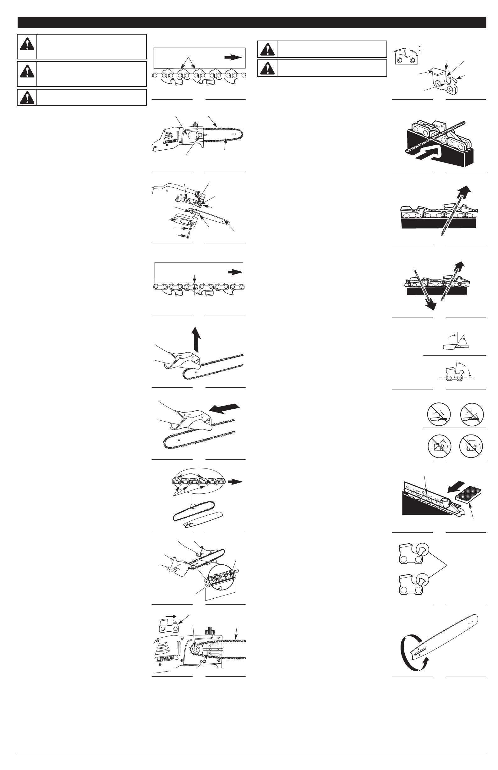
10
ENTRETIEN DE LA CHAÎNE
Pour une coupe rapide et homogène, il est essential d’entretenir la chaîne
correctement. Les conditions suivantes indiquent que la chaîne a besoin d’être
affûtée :
• Les copeaux de bois sont petits et poudreux.
• Il faut pousser sur la tronçonneuse pour traverser le bois lors de la coupe.
• La chaîne ne coupe que d’un côté.
Lors de l’entretien de la chaîne, tenez compte de ce qui suit :
• Le réglage du limiteur de profondeur (ou épaisseur du copeau) détermine la
hauteur à laquelle les gouges pénètrent le bois et la taille des copeaux de
bois découpés (Fig. 21). Une épaisseur de copeaux trop importante accroît le
risque de rebond. Une épaisseur de copeaux trop faible diminue la taille des
copeaux, et par conséquent la capacité de coupe de la chaîne.
• Si les dents de la chaîne ont heurté des objets durs, tels que des clous ou
des pierres, ou qu’elles ont été abrasées par de la boue ou du sable
recouvrant le bois, confiez l’affûtage de la chaîne à un concessionnaire agréé.
REMARQUE : Vérifiez l’usure ou les dommages éventuels du pignon
d'entraînement lors du remplacement de la chaîne. Si l'appareil présente des
signes d'usure ou de dommages, ne l’utilisez pas.
REMARQUE : Si vous n'avez pas bien compris la procédure à suivre pour
l'affûtage des gouges après avoir lu les instructions ci-dessous, confiez
l’affûtage de la chaîne à un concessionnaire agréé ou remplacez la chaîne par
une chaîne à faible rebond.
AFFÛTER LES GOUGES
Prenez soin de limer toutes les gouges aux angles spécifiés et à la même
longueur. Une coupe rapide ne peut être obtenue que lorsque toutes les gouges
sont uniformes.
• La chaîne doit être suffisamment tendue pour ne pas avoir de jeu. Limez
toujours au milieu du guide. Portez des gants pour votre sécurité.
• Utilisez une lime ronde et un porte-lime.
• Maintenez le niveau de la lime à celui de la plaque supérieure de la dent (fig.
22). Ne laissez pas la lime plonger ou se balancer.
• Avec une pression légère mais ferme, limez vers le coin avant de la dent (Fig.
23). Enlevez la lime de la gouge avant de revenir au début du limage d’affûtage.
• Donnez quelques coups de lime vifs sur chaque dent. Limez toutes les gouges
de gauche dans un sens (Fig. 24). Puis déplacez-vous de l’autre côté et limez
les gouges de droite dans le sens opposé (Fig. 36). Nettoyez régulièrement
votre lime avec une brosse métallique pour en retirer les limailles.
Angle de limage de la plaque supérieure
• CORRECT (30°) – Les porte-limes sont munis de repères pour aligner
correctement la lime et produire l’angle parfait pour la plaque supérieure (Fig. 25).
• INCORRECT (MOINS DE 30°) – Pour couper en biais (Fig. 26).
• INCORRECT (PLUS DE 30°) – Ceci créé un bord plumeté que émousse
rapidement.
Angle de limage de la plaque latérale
• CORRECT (80°) – Cela se produit automatiquement lorsque le diamètre
correct de lime est utilisé dans le porte-lime (Fig. 25).
• INCORRECT (CROCHET) – Ceci provoque « l’accrochage » de la chaîne, qui
émousse alors rapidement, ce qui augmente le risque de rebond. Un crochet
se forme lorsqu'une lime de trop faible diamètre est utilisée ou si la lime est
tenue trop bas (Fig. 26).
• INCORRECT (INCLINAISON ARRIÈRE) – Ceci provoque un effort
d’avancement trop important, dont résulte une usure excessive de la chaîne
et du guide. Une inclinaison arrière est causée par l’utilisation d’une lime d'un
trop gros diamètre ou qui est tenue trop haute.
MAINTENIR UNE PROFONDEUR DE JAUGE UNIFORME
• Maintenez la profondeur de jauges à 1/32 pouce (0,6 mm) (Fig. 21). Utilisez un
gabarit d’affûtage pour vérifier la profondeur des jauges.
• Vérifiez la profondeur de jauges à chaque affûtage.
• Utilisez une lime plate et une rainureuse pour diminuer l’épaisseur
uniformément (Fig. 27). Utilisez une rainureuse de 1/32 pouce (0,6 mm). Après
avoir diminué chaque profondeur de jauge, rétablissez la forme d’origine en
arrondissant l'avant (Fig. 28). Faites attention de ne pas endommager les
maillon-guides adjacents avec le bord de la lime.
• Les limiteurs de profondeur doivent être ajustés avec la lime plate dans la
même direction que celle dans laquelle la gouge adjacente a été limée avec la
lime ronde.
• Faites attention de ne pas toucher la face de la gouge avec la lime plate
lorsque vous ajustez les limiteurs de profondeur.
ENTRETENIR LE GUIDE
Après chaque semaine d’utilisation, retournez le guide sur la tronçonneuse pour
répartir l’usure et assurer une durée de vie maximale (Fig. 29). Vérifiez régulièrement
que le guide n’est pas endommagé. L’amincissement et l’ébarbage des rails du
guide (les rebords de chaque côté de la rainure du guide) font partie de l’usure
normale du guide. Ces défauts devraient être limés aussitôt qu’ils apparaissent.
Un guide présentant les défauts suivants devrait être remplacé :
• Une usure à l’intérieur des rails du guide qui laisse la chaîne s’écarter sur les côtés.
• Un guide tordu.
• Des rails fissurés ou cassés.
• Des rails écartés.
AJUSTER LA TENSION DE LA CHAINE
La chaîne doit être retendue chaque fois que les faces des maillon-guides
retombent de la rainure du guide (fig. 12). Vérifiez la tension de la chaîne avant
chaque utilisation et régulièrement en cours d’utilisation.
REMARQUE : Les chaînes neuves ont tendance à s'étirer. Vérifiez régulièrement la
tension de la chaîne et resserrez-la si nécessaire.
1. Coupez le moteur, assurez-vous que le bouton de verrouillage est dans la
position ARRÊT ou verrouillé, puis retirez la batterie. Consultez Retirer la
batterie dans la section Instructions de montage.
2. Desserrez légèrement le boulon du cache du guide (Fig. 13).
3. Tournez le boulon de réglage de tension de la chaîne (Fig. 14) dans le sens
des aiguilles d’une montre à l’aide d’une clé Allen pour tendre la chaîne. La
tension souhaitée dépend de la température de la chaîne:
• Tension d’une chaîne froide - Une chaîne froide est correctement tendue
lorsqu'il n’y a pas de fléchissement sur le dessous du guide et qu’elle est
parfaitement ajustée contre le guide avec les maillon-guides insérés dans
la rainure du guide.
• Tension d’une chaîne chaude - Lors d’une utilisation normale, la
température de la chaîne augmente. Les maillon-guides d’une chaîne
chaude correctement tendue retombent de la rainure du guide d’environ
1/16 pouce (1,3 mm) (Fig. 15).
4. Une fois la chaîne ajustée, soulevez l’extrémité du guide pour vérifier qu’elle
est correctement tendue (Fig. 16). Si la chaîne est toujours trop détendue,
relâchez l’extrémité du guide et tournez le boulon de réglage de tension de la
chaîne d’1/2 tour dans le sens des aiguilles d’une montre. Répétez ce
processus jusqu'à ce que la tension souhaitée soit obtenue.
REMARQUE : Si la chaîne est trop tendue, elle ne tournera pas. Pour détendre la
chaîne, tournez le boulon de réglage de tension de la chaîne d’1/4 de tour
dans le sens inverse des aiguilles d’une montre. Assurez-vous que la chaîne
peut être tournée à la main sans accrocs (Fig. 17).
5. Tenez l’extrémité du guide et vissez le boulon du cache du guide dans le
sens des aiguilles d’une montre pour le fixer.
RETRAIT/REMPLACEMENT DU GUIDE ET DE LA CHAINE
Utilisez uniquement une chaîne à faible rebond sur cette tronçonneuse. Cette
chaîne à coupe rapide réduit le risque d’effet de rebond lorsqu'elle est
correctement entretenue.
REMARQUE : Lorsque vous remplacez le guide et la chaîne, n'utilisez que des
pièces de rechange recommandées par le fabricant. L'utilisation d’autres
pièces peut se révéler dangereuse ou endommager le produit et ANNULERA
la garantie.
Retrait du guide et de la chaîne usagés
1. Assurez-vous que le bouton de verrouillage est dans la position ARRÊT ou
verrouillé, puis retirez la batterie.
2. Tournez le boulon du cache du guide dans le sens inverse des aiguilles d’une
montre et retirez-le, ainsi que le manchon et le cache du guide (Fig. 14).
3. Retirez le guide et la chaîne de la surface de montage.
4. Retirez la chaîne usagée du guide.
Installer le nouveau guide et la chaîne
1. Étalez la nouvelle chaîne coupante en la disposant en boucle et redressez les
éventuels nœuds. Les gouges sur le dessus du guide doivent faire face à
l’extrémité du guide, dans le sens de la rotation de la chaîne (Fig. 18). S’ils
sont dirigés dans le sens inverse, retournez la boucle.
2. Placez les maillon-guides de la chaîne dans la rainure du guide tel qu’indiqué
(Fig. 19).
REMARQUE : Assurez-vous que la chaîne est correctement installée et que les
gouges sont orientées dans la bonne direction (Fig. 18).
3. Positionnez la chaîne de sorte qu’une boucle se forme à l’arrière du guide.
4. Maintenez la chaîne en position sur le guide et placez la boucle autour du
pignon d'entraînement.
5. Ajustez le guide au ras de la surface de montage de sorte que le goujon du
guide s’insère dans la fente correspondante.
REMARQUE : Lorsque vous placez le guide sur le goujon du guide, assurez-
vous que la broche de réglage de tension de la chaîne s’insère dans l’orifice
correspondant (Fig. 20).
6. Remettez en place le cache du guide, le manchon et le boulon du cache du
guide. Pour serrer, tournez le boulon du cache du guide dans le sens des
aiguilles d’une montre à l’aide d’une clé Allen.
REMARQUE : Resserrez le boulon du cache du guide uniquement à la main. Le
guide doit être suffisamment lâche pour pouvoir ajuster la tension de la chaîne.
7. Ajustez la tension de la chaîne. Consultez les instructions Réglage de la
tension de la chaîne ci-dessus.
ENTRETIEN ET RÉPARATIONS
Rotation de la chaîne
Fig. 20
Pignon d’entraînement
Chaîne
AVERTISSEMENT :
Une chaîne émoussée ou mal
affûtée peut provoquer une vitesse excessive du moteur lors
de la coupe, ce qui peut l’endommager sérieusement.
AVERTISSEMENT :
Une chaîne mal affûtée accroît le
risque de rebond. Une chaîne endommagée qui n’est pas
remplacée ou réparée peut causer de graves blessures.
Plaque
supérieure
Fig. 21
Coin de coupe
Entaille
Fig. 22
Fig. 23
Gouges
de gauche
Fig. 24
Gouges de
droite
Broche de réglage de tension de la chaîne
Limiteur de
profondeur
Profondeur de jauge
1/32 pouce (0,6 mm)
Plaque
latérale
Fig. 27
Fig. 28
Fig. 29
Lime plate
Rainureuse
Rétablissez la
forme d’origine en
arrondissant l'avant
Hauteur de limage
Angle de limage
Fig. 25
Fig. 26
Plaque
supérieure
Moins de 30˚
Plus de 30˚
30˚
Angles de limage
incorrects
Crochet
Inclinaison arrière
80˚
Angles de
limage corrects
Plaque
supérieure
Plaque
latérale
Plaque latérale
Fig. 18
Maillon-guides
de la chaîne
Rotation de
la chaîne
Gouges
Environ 1/16
pouce (1,3 mm)
Fig. 15
Extrémité
du guide
AVERTISSEMENT :
Avant de vérifier, de nettoyer ou
d'entretenir l’appareil, arrêtez le moteur, attendez que toutes
les parties en mouvement se soient arrêtées et retirez la
batterie. Le non respect de ces instructions peut entraîner des
dégâts matériels ou des blessures graves.
Faces
Fig. 12
Boulon du cache
du guide
Fig. 13
AVERTISSEMENT :
Pour éviter des blessures
éventuelles, ne touchez ou n’ajustez jamais la chaîne de coupe
quand le moteur tourne. La chaîne de coupe est extrêmement
tranchante ; portez toujours des gants de protection quand
vous entretenez la chaîne.
ATTENTION :
Une chaîne tendue lorsqu’elle est chaude
peut s’avérer trop tendue une fois refroidie. Vérifiez la “tension
à froid” avant la prochaine utilisation.
Extrémité
du guide
Pignon d’entraînement
Fig. 14
Broche de réglage
de tension de la
chaîne
Goujon du guide
Cache du
guide
Chaîne
Guide
Fente du
goujon du
guide
Rainure du
guide
Boulon du
cache du guide
Cache
du guide
Orifice de la
broche de
réglage de
tension de
la chaîne
Boulon de réglage
de tension de la
chaîne
Manchon
Fig. 19
Fig. 16
Fig. 17
Rainure du
guide
Maillon-guides
de la chaîne
Page 11

CAUSE SOLUTION
11
La batterie n’est pas assez chargée Chargez la batterie
INSTRUCTIONS DE NETTOYAGE
REMARQUE : Il est normal que l'huile s'écoule de l'appareil quand il n'est pas en service. Tenez-en compte lors du rangement de l’appareil.
• Retirez la batterie de l’appareil.
• Desserrez la chaîne si elle a été retendue à la température de fonctionnement au cours des travaux de coupe. La chaîne se contracte
en refroidissant. Si elle n'est pas desserrée, elle peut endommager la transmission et les roulements.
• Frottez l’extérieur de l’appareil avec un linge humide. N’éclaboussez pas l’appareil avec de l’eau. N’utilisez pas de solvants ou de
détergents agressifs. Si vous préparez l'appareil pour un stockage à long terme (trois mois ou plus), retirez la chaîne et le guide, puis
nettoyez soigneusement l'appareil avec un chiffon humide. Utilisez une brosse à poils durs, non métallique, pour enlever les débris de
la rainure du guide et de la chaîne. Lorsque vous avez terminé, remontez l’appareil. Consultez la section Retrait/Remplacement du
guide et de la chaîne.
• Vaporisez le guide et la chaîne avec une huile antirouille.
INSTRUCTIONS POUR LE RANGEMENT
• Suivez les instructions de nettoyage mentionnées ci-dessus.
• Placez le fourreau sur le guide et la chaîne.
• Rangez l’appareil dans un endroit sec et en hauteur et/ou sous clé, hors de la portée des enfants et des personnes non autorisées.
AVERTISSEMENT :
Ne laissez pas du liquide de frein, de l’essence, des produits à base de pétrole, de l’huile
pénétrante, etc. entrer en contact avec des pièces en plastique. Ces produits chimiques peuvent endommager, affaiblir ou
détruire le plastique, ce qui peut entraîner des blessures graves.
SPÉCIFICATIONS*
* L’ensemble des caractéristiques sont basées sur les toutes dernières informations disponibles sur le produit à l’impression de ce
guide. Nous nous réservons le droit d’effectuer des modifications à tout moment sans notification préalable.
Type . . . . . . . . . . . . . . . . . . . . . . . . . . . . . . . . . . . . . . . . . . . . . . . . . . . . . . . . . . . . . . . . . . . . . . . . . . . . . . . . . . . . . . . . . . . Sans fil, sur batterie
Moteur. . . . . . . . . . . . . . . . . . . . . . . . . . . . . . . . . . . . . . . . . . . . . . . . . . . . . . . . . . . . . . . . . . . . . . . . . . . . . . . . . . . . . . . . . . . . . . . . . . . . . . 20 V
Vitesse du moteur. . . . . . . . . . . . . . . . . . . . . . . . . . . . . . . . . . . . . . . . . . . . . . . . . . . . . . . . . . . . . . . . . . . . . . . . . . . . . . . . . . . . . . . . 3000 t/min
Longueur du guide . . . . . . . . . . . . . . . . . . . . . . . . . . . . . . . . . . . . . . . . . . . . . . . . . . . . . . . . . . . . . . . . . . . . . . . . . . . . . . . 8 pouces (20,32 cm)
Pas de chaîne . . . . . . . . . . . . . . . . . . . . . . . . . . . . . . . . . . . . . . . . . . . . . . . . . . . . . . . . . . . . . . . . . . . . . . . . . . . . . . . . . . . . 3/8 pouce (9,5 mm)
Type de chaîne. . . . . . . . . . . . . . . . . . . . . . . . . . . . . . . . . . . . . . . . . . . . . . . . . . . . . . . . . . . . . . . . . . . . . . . . . . Chaîne de 8 pouces (20,32 cm)
Type de guide . . . . . . . . . . . . . . . . . . . . . . . . . . . . . . . . . . . . . . . . . . . . . . . . . . . . . . . . . . . . . . . . . . . . . . . . . . . Guide de 8 pouces (20,32 cm)
Vitesse de la chaîne . . . . . . . . . . . . . . . . . . . . . . . . . . . . . . . . . . . . . . . . . . . . . . . . . . . . . . . . . . . . . . . . . . . . . . . . . . . . . . 6 m/s (19,68 pieds/s)
Capacité du réservoir de lubrifiant . . . . . . . . . . . . . . . . . . . . . . . . . . . . . . . . . . . . . . . . . . . . . . . . . . . . . . . . . . . . . . . . . . . . . . . . . 1,5 oz (45 ml)
Poids (avec batterie). . . . . . . . . . . . . . . . . . . . . . . . . . . . . . . . . . . . . . . . . . . . . . . . . . . . . . . . . . . . . . . . . . . . . . . . . . . . . . . . . . . . . . 11 lb (5 kg)
NETTOYAGE ET RANGEMENT
La chaîne est émoussée Affûtez la chaîne
La chaîne est montée à l’envers Inversez le sens de la chaîne
RÉSOLUTION DES PROBLÈMES
REMARQUE : Pour un entretien au-delà des petits réglages mentionnés ci-dessus, ou pour obtenir des informations sur les pièces de
rechange, veuillez appeler le service à la clientèle au 1-877-282-8684 (E.U.) ou 1-800-668-1238 (Canada).
La chaîne est trop tendue Ajustez la tension de la chaîne
Le réservoir de lubrifiant est vide Remplissez le réservoir de lubrifiant
La chaîne est trop tendue Ajustez la tension de la chaîne
Le guide et la chaîne sont mal assemblés Consultez la section Retrait/Remplacement du guide et de la chaîne
Le guide et la chaîne sont endommagés Examinez le guide et la chaîne pour voir s’ils sont endommagés
Le mécanisme d'entraînement est endommagé Consultez la section Information sur l’entretien et le service
après-vente
LA CHAINE NE TOURNE PAS ALORS QUE LE MOTEUR EST EN MARCHE
LA CHAÎNE TOURNE MAIS NE COUPE PAS
ACCESSOIRES (VENDUS SÉPARÉMENT)
Modèle
A59 LBTY . . . . . . . . . . . . .
A59LCHGR . . . . . . . . . . . .
Description
Batterie lithium-ion 20V
Chargeur de batterie lithium-ion 20V
Nº de pièce
753-06579 . . . . . . .
753-06580 . . . . . . .
LE MOTEUR MARCHE AU RALENTI OU NE MARCHE PAS DU TOUT
REMARQUES
LE GUIDE ET LA CHAÎNE CHAUFFENT ET ÉMETTENT DE LA FUMÉE OU SONT COINCÉS
PIÈCES DE RECHANGE
Description
Chaîne de 8 pouces (20,32 cm)
Guide de 8 pouces (20,32 cm)
Nº de pièce
753-06628. . . . . . . . . . . . . . . . . . . . . . . . . . . . . . . . . . . . . .
753-06630. . . . . . . . . . . . . . . . . . . . . . . . . . . . . . . . . . . . . .
Page 12

12
REMARQUES
Page 13
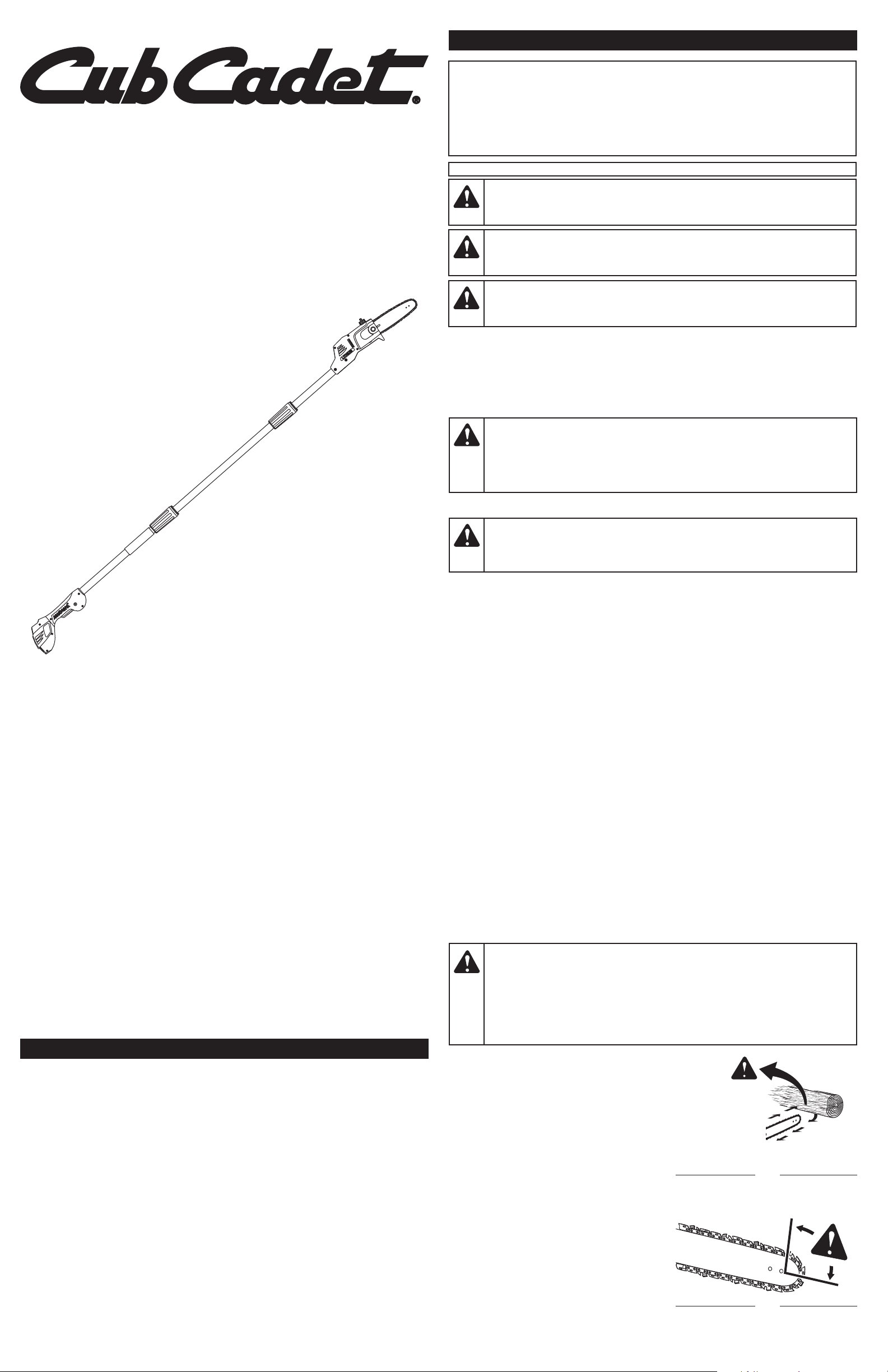
LEA TODAS LAS INSTRUCCIONES ANTES DE OPERAR LA UNIDAD
FUNDAMENTOS DE SEGURIDAD
• Lea con cuidado y comprenda el manual del operador de la batería que propulsa esta unidad.
• Familiarícese completamente con los controles y el uso apropiado de la unidad. Sepa cómo apagar
la unidad y desactivar los controles con rapidez.
• ¡Manténgase alerta! No opere esta unidad si está cansado, enfermo, o bajo los efectos del alcohol,
drogas o medicamentos.
• No permita nunca que los niños operen la unidad. No permita nunca que operen la unidad adultos
sin los debidos conocimientos.
• No permita que la unidad para ser utilizado como un juguete.
• Asegúrese de que todos los accesorios de protección y seguridad estén adecuadamente
instalados antes de comenzar a operar la unidad.
• Conserve estas instrucciones. Consúltelas con frecuencia y utilícelas para enseñar a otros
usuarios. Si le presta esta unidad a alguna otra persona, préstele también estas instrucciones.
PRECAUCIONES DE SEGURIDAD PRELIMINARES
• NO se confíe exclusivamente en los dispositivos de seguridad incorporados en la unidad.
• Mantenga a los espectadores, especialmente a los niños y animales domésticos, a una distancia
de al menos 50 pies (15 m). Si alguien entra al área en la que se está trabajando, ¡apague la unidad!
• Mantenga limpia el área de trabajo. Las áreas de trabajo desorganizadas atraen los accidentes. No
comience a cortar hasta que el área de trabajo esté despejada y libre de obstrucciones, haya una
pisada firme y tenga una senda prevista para apartarse de las ramas caídas.
• Utilice la debida protección de los ojos y oídos siempre que opere la unidad. Lleve puestas gafas o
lentes de seguridad protegidas a ambos lados que estén marcados como que cumplen con las
normas ANSI Z87.1-1989. Si no lo hace así, los objetos despedidos o caídos podrían ocasionarle
lesiones graves en los ojos. Si la operación levanta polvo, lleve puesta una máscara facial o para
protegerse contra el polvo. Cuando opere la unidad a una altura por encima de la cabeza, póngase
un casco protector u otro tipo prenda para la protección de la cabeza.
• Vístase correctamente, lleve puesta ropa gruesa, cómodamente ajustada al cuerpo (pantalones largos
y camisa de mangas largas), guantes protectores antideslizantes y botas de seguridad con punta de
acero. No use ropa holgada, alhajas, pantalones cortos, sandalias ni esté descalzo. Asegure su cabello
por encima de los hombros para evitar que se enrede con las piezas en movimiento.
• Use la unidad únicamente con la luz del día o con buena luz artificial.
• Use la unidad solamente con el propósito para el que fue diseñada.
COMPRENDER EL CONTRAGOLPE
• El contragolpe de giro puede ocurrir cuando la punta
superior de la barra guía se pone en contacto con un
objeto mientras la cadena se está moviendo (Fig. 1 y 2).
Esto puede hacer que la cadena perfore el objeto y se
detenga momentáneamente. La barra guía entonces
salta y se da vuelta, veloz como un rayo, retrocediendo
en dirección al operador.
• El contragolpe de pellizco puede ocurrir cuando el leño
a cualquier lado de un corte cerca y pellizca la cadena
de la sierra que se mueve a lo largo de la parte superior
de la barra guía. Esto puede provocar el paro
instantáneo de la cadena. La fuerza que actúa sobre la
cadena se invierte e induce en la sierra un movimiento
contrario que la lanza directamente hacia el operador.
• La succión puede ocurrir cuando la cadena que se
mueve por debajo de la barra guía hala un objeto
extraño y lo introduce dentro del leño. Esto puede hacer
que la cadena se pare de repente. La fuerza contraria
hala entonces la sierra y la aleja del operador, lo que
puede dar lugar a la pérdida del control sobre la sierra.
PRECAUCIONES DE SEGURIDAD PARA EVITAR EL
CONTRAGOLPE
• NO intente alcanzar demasiado lejos.
• NO haga cortes con la punta de la barra guía.
• NO deje nunca que la punta de la barra guía se
ponga en contacto con ningún objeto como un
tronco, rama, el terreno ni cualquier otra obstrucción. Al cortar, quite o evada cualquier obstrucción
que pudiera impactar la punta de la barra guía.
Manual del Operador
Sierra de Pértiga con batería
de ión de litio de 20 Voltios
PS59L
TABLA DE CONTENIDO
Información sobre servicio . . . . . . . . . . . . . . . . . . . . . . . . . . . . . . . . . . . . . . . . . . . . . . . . . . . . . . .13
Información de seguridad . . . . . . . . . . . . . . . . . . . . . . . . . . . . . . . . . . . . . . . . . . . . . . . . . . . . . . . .13
Conozca su unidad . . . . . . . . . . . . . . . . . . . . . . . . . . . . . . . . . . . . . . . . . . . . . . . . . . . . . . . . . . . . .15
Instrucciones de ensamblaje . . . . . . . . . . . . . . . . . . . . . . . . . . . . . . . . . . . . . . . . . . . . . . . . . . . . .15
Instrucciones de Arranque y Parada . . . . . . . . . . . . . . . . . . . . . . . . . . . . . . . . . . . . . . . . . . . . . . .15
Instrucciones de operación . . . . . . . . . . . . . . . . . . . . . . . . . . . . . . . . . . . . . . . . . . . . . . . . . . . . . .15
Instrucciones de mantenimiento y reparación . . . . . . . . . . . . . . . . . . . . . . . . . . . . . . . . . . . . . . . .16
Limpieza y almacenamiento . . . . . . . . . . . . . . . . . . . . . . . . . . . . . . . . . . . . . . . . . . . . . . . . . . . . . .17
Localización y solución de problemas . . . . . . . . . . . . . . . . . . . . . . . . . . . . . . . . . . . . . . . . . . . . . .17
Especificaciones . . . . . . . . . . . . . . . . . . . . . . . . . . . . . . . . . . . . . . . . . . . . . . . . . . . . . . . . . . . . . . .17
Información sobre garantía . . . . . . . . . . . . . . . . . . . . . . . . . . . . . . . . . . . . . . . . . . . . . . . . . . . . . . .20
INFORMACIÓN DE SEGURIDAD
Utiliza batería de ión de litio de 20V A59 LBTY (se vende por separado)
Utiliza cargador de baterías de ión de litio de 20V A59LCHGR (se vende por separado)
• INSTRUCCIONES DE SEGURIDAD IMPORTANTES •
ADVERTENCIA:Lea cuidadosamente el manual del operador
completo antes de intentar ensamblar, operar o dar mantenimiento a la unidad. Siga todas
las instrucciones de seguridad. No hacerlo puede ocasionar daños a la propiedad o a que
usted y/u otras personas sufran lesiones de gravedad.
PELIGRO:
El contragolpe se puede producir cuando la nariz o punta de la barra
guía toca un objeto o cuando el leño cerca y pellizca la cadena de la sierra durante el corte. En
algunos casos, el contacto de la punta puede producir una reacción de retroceso veloz como un
rayo y empujar aceleradamente la barra guía hacia atrás, en dirección al operador. El pellizco de la
cadena de la sierra a lo largo de la parte superior de la barra guía puede empujar aceleradamente
esta última hacia atrás, en dirección al operador. Cualquiera de estas reacciones puede dar lugar a
la pérdida del control sobre la sierra, lo que podría traer como consecuencia graves lesiones al
operador. El contacto con objetos extraños en el interior del leño también puede provocar una
pérdida del control sobre la sierra de cadena.
Fig. 1
Contragolpe
de giro
769-06477 P02 06/11
NO DEVUELVA ESTA UNIDAD AL VENDEDOR. PARA SOLICITAR SERVICIO POR LA GARANTÍA,
DEBERÁ PRESENTAR PRUEBA DE SU COMPRA.
Para solicitar asistencia en relación con el ensamblaje, los controles, la operación o el mantenimiento de la
unidad, llame al Departamento de Atención al Cliente: 1-877-282-8684 (EE.UU.) o 1-800-668-1238 (Canadá).
Puede encontrar más información sobre la unidad en nuestro sitio Web: www.cubcadet.com (EE.UU.)
o www.cubcadet.ca (Canadá).
Llame al Departamento de Atención al Cliente para solicitar piezas de repuesto. Al dar mantenimiento,
utilice sólo piezas de repuesto idénticas.
GUARDE ESTAS INSTRUCCIONES
Toda la información, ilustraciones y especificaciones que contiene este manual se basan en la
información más reciente disponible en el momento de impresión del manual. Nos reservamos el
derecho de hacer cambios en cualquier momento sin previo aviso.
Copyright© 2011 MTD SOUTHWEST INC. Todos los derechos reservados.
INFORMACIÓN SOBRE SERVICIO
PROPOSICIÓN 65 DEL ESTADO DE CALIFORNIA
ADVERTENCIA:Los bornes y terminales de las baterías, así como
determinados productos terminados contienen plomo, compuestos de plomo y otros
productos químicos de los que el estado de California tiene conocimiento provocan cáncer,
malformaciones congénitas u otros daños al sistema reproductor. Lávese las manos
después de manipularlo.
PELIGRO:
Indica un peligro EXTREMO.
El no obedecer una señal de seguridad de PELIGRO RESULTARÁ en que usted u otras
personas puedan sufrir lesiones graves o la muerte.
ADVERTENCIA:Indica un peligro GRAVE.
El no obedecer una señal de ADVERTENCIA de seguridad PUEDE conducir a que usted u
otras personas sufran graves lesiones.
PRECAUCIÓN:
Indica un peligro MODERADO.
El no obedecer una señal de PRECAUCIÓN de seguridad PUEDE conducir a daños a la
propiedad o a que usted u otras personas se lesionen.
¡IMPORTANTE! Indica información mecánica especial.
NOTA: Indica información general importante adicional.
SÍMBOLO SIGNIFICADO
• SÍMBOLOS DE ALERTA DE SEGURIDAD •
Los símbolos de alerta de seguridad se utilizan para llamar su atención sobre posibles peligros.
Estos símbolos y sus explicaciones merecen toda su atención y comprensión. Las advertencias de
seguridad no eliminan ningún peligro por sí mismas. Las instrucciones o advertencias que ofrecen
no sustituyen a las medidas adecuadas de prevención de accidentes. El objetivo de estas
instrucciones de seguridad no consiste en abarcar cada una de las posibles situaciones que pueden
ocurrir. Si surgen preguntas, llame al Departamento de Atención al Cliente al 1-877-282-8684
(EE.UU.) o al 1-800-668-1238 (Canadá).
Fig. 2
Zona peligrosa de
contragolpe
Page 14
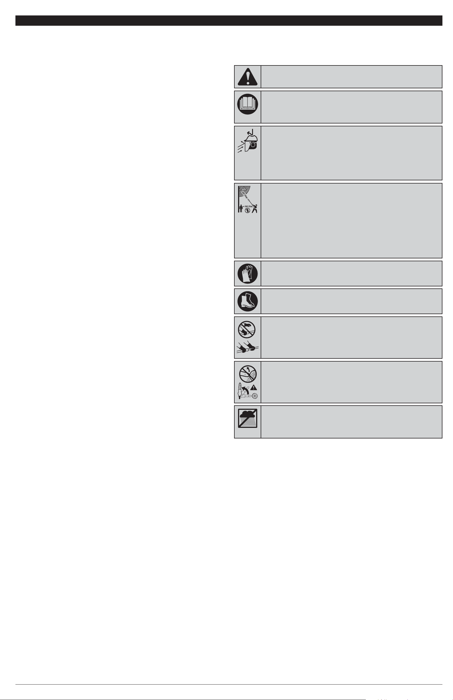
14
INFORMACIÓN DE SEGURIDAD
• SÍMBOLOS INTERNACIONALES Y DE SEGURIDAD •
Este manual del operador describe símbolos y figuras internacionales y de seguridad que
pueden aparecer en este producto. Lea el manual del operador para obtener información
completa acerca de la seguridad, el ensamblaje, la operación, el mantenimiento y la reparación.
• SÍMBOLO DE ALERTA DE SEGURIDAD
Indica peligro, advertencia o precaución. Puede ser utilizado junto con otros
símbolos o pictografías.
• LEA EL MANUAL DEL OPERADOR
ADVERTENCIA:Lea el(los) manual(es) del operador y siga
todas las advertencias e instrucciones de seguridad. No hacerlo puede
ocasionar lesiones graves al operador y/o a los espectadores.
• USE PROTECCIÓN PARA LA CABEZA, OJOS Y OÍDOS
ADVERTENCIA:Los objetos que salen despedidos y el
ruido fuerte pueden ocasionar lesiones oculares severas y pérdida de la
audición. Póngase gafas o lentes de protección que cumplan las normas
ANSI Z87.1-1989 y protección de los oídos cuando opere esta unidad.
Protéjase la cabeza al operar la unidad; los objetos caídos pueden ocasionar
lesiones graves en la cabeza. Use una pantalla que le cubra el rostro por
completo cuando sea necesario.
SÍMBOLO SIGNIFICADO
• LLEVE PUESTOS ZAPATOS DE SEGURIDAD
Póngase zapatos de seguridad antideslizantes al utilizar este equipo.
•
PÓNGASE GUANTES DE SEGURIDAD
Póngase guantes protectores antideslizantes para trabajo pesado al
manipular la unidad.
• NO LA USE CUANDO LLUEVA
ADVERTENCIA:Evite ambientes peligrosos. No opere nunca
la unidad bajo la lluvia ni en lugares húmedos ni mojados. La humedad es un
peligro de descarga eléctrica.
• ADVERTENCIA DE CONTRAGOLPE
Se deberá evitar el contacto de la punta de la barra guía con cualquier
objeto. Este contacto puede dar lugar a que la barra guía se eleve de
repente y se mueva para atrás, lo que podría provocar lesiones graves.
• MANTENGA ALEJADOS A LOS ESPECTADORES
ADVERTENCIA:Mantenga a todos los espectadores,
especialmente a los niños y animales domésticos, a una distancia de al
menos 50 pies (15 m). Si alguien entra al área en la que se está trabajando,
¡apague la unidad!
• LAS LÍNEAS DE ALTA TENSIÓN PUEDEN OCASIONAR LESIONES GRAVES
ADVERTENCIA:Do not operate this unit near power lines.
Contact with a power line may cause serious injury or damage to the unit.
Maintain a clearance of at least 50 feet (15 m) between the pole saw
(including any branches it is contacting) and any electrical line.
• NO corte más de una rama a la vez.
• NO retuerza la sierra al retirar la barra guía de un corte bajo.
• No arranque nunca la sierra cuando la barra guía esté dentro de un corte ya hecho. Sea
extremadamente cuidadoso cuando vuelva a entrar la sierra en un corte.
• Agarre firmemente la unidad cuando el motor esté funcionando. Mantenga la mano derecha sobre la
empuñadura y la izquierda encima del eje de la pértiga, en una posición que le dé un soporte
adecuado. Sujete firmemente con el pulgar y los dedos rodeando la empuñadura y el eje de la
pértiga. Párese ligeramente a la izquierda de la unidad para evitar estar en línea recta con la cadena
de la sierra. Siga todas las instrucciones que se describen en la sección Instrucciones de Operación.
• Mantenga una posición y un equilibrio adecuados en todo momento.
• Al arrancar la unidad, deje siempre que el motor alcance su velocidad máxima antes de empezar a
cortar. Oprima completamente el gatillo del interruptor y mantenga una velocidad de corte estable.
Las velocidades más lentas aumentan el chance de contragolpe. Sostenga el chasis de la sierra
firme contra el leño o madero.
• Esté pendiente de los troncos, ramas u otros objetos que cambian de lugar y pudieran pellizcar la
cadena, o caerle encima, durante el corte.
• Si usa calzos, use solo cuñas de plástico o madera. No use ningún metal para mantener abierto un corte.
• Siga las instrucciones del fabricante para afilar y dar mantenimiento a la cadena de la sierra.
• Utilice solamente guías y cadenas de repuesto especificadas por el fabricante o sus equivalentes.
• Utilice dispositivos como cadenas de bajo contragolpe, protectores de la punta de la barra guía, frenos de
cadena y barras guía especiales, los que reducen los riesgos relacionados con el contragolpe. Conforme
a la CSA Z62.3, no hay otros componentes de repuesto para lograr protección para el contragolpe.
• La cadena de sierra de bajo contragolpe es la que satisface los requisitos de funcionamiento ANSI
B175.1-1991 y está de acuerdo con la CSA Z62.3. No utilice ninguna otra cadena de repuesto, excepto
que reúna estos mismos requisitos para el modelo en específico. A medida que las cadenas de sierra
se afilan, se pierde parte de la calidad de contragolpe y es recomendable poner más cuidado.
OTRAS PRECAUCIONES DE SEGURIDAD
• ¡NO utilice nunca la unidad con una sola mano! Si la unidad se opera con una sola mano, pueden
ocurrir lesiones graves al operador, los ayudantes o espectadores. Esta unidad está diseñada para
ser operada con ambas manos.
• NO manipule la unidad con las manos mojadas.
• NO opere nunca una sierra de pértiga subido a un árbol ni en una escalera a menos que esté
específicamente entrenado para hacerlo.
• NO exponga la unidad a la lluvia. No utilice la unidad en lugares húmedos ni mojados ni en esas
condiciones.
• NO haga funcionar la unidad sobre superficies mojadas.
• NO utilice la unidad en presencia de líquidos o gases inflamables.
• NO ponga a funcionar una unidad que esté dañada, incorrectamente ajustada o que no esté
completamente ensamblada con seguridad. Asegúrese de que la unidad se detiene al soltar el
gatillo. No use la unidad si el interruptor no enciende y apaga la unidad adecuadamente o si el
engatillado del interruptor no funciona.
• NO intente NUNCA realizar operaciones más allá de la capacidad o experiencia del operador.
• NO corte NUNCA cerca de cables eléctricos ni líneas de alta tensión.
• NO fuerce la sierra de pértiga, en particular, cuando está próximo a finalizar un corte. Hará un
trabajo mejor y más seguro a la velocidad para la que fue diseñada.
• Para disminuir el riesgo de descarga eléctrica, evite el contacto con conductores conectados a
tierra, por ejemplo, tuberías de metal o cercas de alambre.
• Cuando el motor esté funcionando, mantenga todas las partes del cuerpo alejadas de la cadena de
la sierra. Antes de arrancar la sierra, asegúrese de que la cadena de la sierra no haga contacto con
ningún objeto.
• Apague siempre el motor cuando la operación se demore, al colocar la unidad en el piso o al
caminar de un lugar a otro. Esté seguro que la cadena se detenga por completo.
• Para evitar un arranque accidental, no transporte nunca la unidad con los dedos colocados sobre
el gatillo del interruptor.
• Mueva siempre la sierra de pértiga sin la batería y con el dedo fuera del gatillo del interruptor, así
como con la barra guía y la cadena de la sierra, enfundadas en la vaina y colocadas para atrás.
• Cerciórese siempre de que el botón del seguro esté bloqueado o en posición APAGADO antes de
instalar o quitar la batería.
• Corte madera solamente. No use nunca la sierra de pértiga para fines para los que no fue diseñada.
• Al cortar una rama que está bajo tensión, manténgase alerta del retorno elástico ya que, al liberarse
la tensión de las fibras de la madera, el operador podría ser golpeado.
• Ponga cuidado extremo al cortar matorrales de menor tamaño y retoños de árboles, ya que los
tallos y ramas más finos pueden engancharse en la cadena de la sierra y golpear al operador o
hacerle perder el equilibrio.
• Esta unidad está diseñada para que los propietarios de viviendas, labradores y campistas la usen
con poca frecuencia, así como para aplicaciones generales como trozar, podar, etc. No está
diseñada para uso prolongado. Si se piensa utilizar durante prolongados períodos de operación,
puede ocasionar problemas circulatorios en las manos del usuario debido a la vibración. Es posible
que sea conveniente utilizar una sierra con características antivibratorias.
SEGURIDAD DEL MANTENIMIENTO Y ALMACENAJE
• NO realice NUNCA trabajos de mantenimiento que no sean los descritos en este manual. No trate
de repararla; la unidad no tiene piezas dentro que puedan ser reparadas por el usuario.
• Siga todas las instrucciones de mantenimiento de este manual.
• Antes de inspeccionar, dar mantenimiento, limpiar, guardar, transportar o reemplazar cualquier
pieza de la unidad:
1. Asegúrese de que todas las partes en movimiento se hayan detenido.
2. Deje que el motor se enfríe.
3. Cerciórese de que el botón del seguro esté bloqueado o en posición APAGADO.
4. Quite la batería.
• Nunca quite, modifique ni haga que no funcione ningún dispositivo provisto con la unidad.
• Para un trabajo más efectivo y seguro, cerciórese de que la barra guía y la cadena estén
adecuadamente limpias, lubricadas, apretadas y afiladas. Compruebe frecuentemente la
adecuación del ajuste de la barra guía y la cadena.
• Inspeccione frecuentemente la unidad para ver si ha sufrido daños. Antes de volverla a utilizar, se
revisará cuidadosamente cualquier pieza dañada para determinar que trabajará adecuadamente y
que realizará la función debida. Compruebe la alineación de las partes en movimiento, el atasco de
las partes en movimiento, la rotura de piezas y cualquier otra condición que pueda afectar su
operación. Las piezas que estén dañadas deben ser debidamente reparadas o reemplazadas.
• Utilice solamente piezas de repuesto y accesorios del fabricante original, las que están
específicamente diseñadas para mejorar el rendimiento y maximizar la operación segura del
producto. No hacerlo puede ocasionar un mal funcionamiento y posibles lesiones. Utilice
solamente la cadena y la barra guía que se suministran con el producto.
• Saque la batería de la unidad cuando no la esté utilizando.
• Cerciórese de proteger la unidad al transportarla.
• Póngale siempre la funda a la barra guía y a la cadena durante el transporte y el almacenamiento.
• Cuando no la esté utilizando, guarde la unida bajo llave, o en alto, en un lugar adecuado y seco,
para evitar que sea usada por personas no autorizadas o que se dañe. Manténgala fuera del
alcance de los niños.
• Mantenga la empuñadura y el mango de agarre, seco, limpio y libre de residuos, aceites y grasas.
Limpie la unidad después de usarla. No moje nunca ni rocíe la unidad con agua ni con ningún otro
líquido. No utilice solventes ni detergentes fuertes.
• No utilice la unidad si se cayó al agua.
• USE AMBAS MANOS
Siempre use ambas manos al operar la sierra de pértiga. Nunca opere nunca
la unidad con una sola mano.
GUARDE ESTAS INSTRUCCIONES
Page 15

15
Esta unidad necesita ensamblaje. La cadena de la sierra sobre la barra guía podría aflojarse; remítase a Ajustar la Tensión de la Cadena de
la sección Instrucciones de Mantenimiento y Reparación.
DESEMPAQUE
• Saque con cuidado el producto y los accesorios de la caja.
• Inspeccione minuciosamente el producto para tener la seguridad de que no se rompió ni dañó nada durante el envío.
• No deseche los materiales de envase y embalaje hasta tanto no haya inspeccionado minuciosamente y operado satisfactoriamente el producto.
• Si hay alguna pieza dañada o que falta, llame al 1-877-282-8684 (EE.UU.) o al 1-800-668-1238 (Canadá) para solicitar ayuda.
ENSAMBLAJE DE PÉRTIGAS
Debe haber tres pértigas (Fig. 3).
1. Inserte la pértiga de extensión en la pértiga de soporte y deslícelas
a la vez. Los tubos son ovoides y asentarán en sentido único.
2. Baje el collarín de la pértiga de extensión hasta la base de rosca
de la pértiga de soporte y déle vueltas a la derecha, para
apretarlo (Fig. 6).
3. Repita este proceso para fijar la pértiga de extensión al cabezal
motorizado.
LUBRICAR LA BARRA GUÍA Y LA CADENA
Utilice solo aceite fabricado para trabajar dentro de un amplio rango de
temperaturas sin que se necesite dilución en el depósito de aceite. No utilice
aceite de motor ni ningún otro aceite a base de petróleo.
NOTA: Esta sierra de pértiga viene de fábrica con el depósito de aceite de la barra
guía vacío. Utilice la botella de aceite que viene con la unidad para la lubricación
de la barra guía y la cadena.
1. Quite la tapa del depósito de aceite de la barra guía (Fig. 4).
2. Vierta con cuidado el aceite en el depósito de aceite de la barra guía.
3. Reponga la tapa y apriete bien.
4. Limpie el exceso de aceite.
5. La unidad está lista para el uso.
NOTA: Debido a que los depósitos de aceite de las guías están diseñados para que el aceite fluya lentamente sobre la cadena, cuente con
la seguridad de comprobar el nivel de aceite cada 15 minutos de operación y rellene el depósito según sea necesario.
NOTA: No utilice aceites sucios, recuperados ni contaminados de alguna otra manera. Podrían dañar la barra guía o la cadena.
¡IMPORTANTE! Deseche el aceite de manera adecuada. Consulte a la autoridad
local de desechos para informarse respecto a las opciones de eliminación
disponibles.
INSTALAR Y QUITAR LA BATERÍA
Siga estas instrucciones a fin de evitar lesiones y reducir el riesgo de descarga
eléctrica o incendio:
• Antes de instalar o quitar la batería, compruebe que el botón del seguro esté
bloqueado o en posición APAGADO. Remítase a las Instrucciones de
Arranque y Parada.
• Antes de inspeccionar, ajustar o realizar el mantenimiento de cualquier parte
de la unidad, cerciórese de sacar la batería y de que el botón del seguro esté
bloqueado o en posición APAGADO.
Instalación de la batería
1. Alinee la lengüeta de la batería con la cavidad en la empuñadura (Fig. 5).
2. Sujete firmemente la sierra de pértiga.
3. Empuje la batería hacia dentro de la cavidad hasta que el seguro de cierre trabe en su lugar.
4.
No haga fuerza al insertar la batería. Ella debe encajar en su posición y hacer “clic”.
Sacar la batería
1. Presione el botón de cierre de la batería y manténgalo oprimido (Fig. 5).
2. Sujete firmemente la sierra de pértiga y hale la batería para sacarla de la cavidad.
NOTA: La batería queda bien ajustada en la cavidad de la empuñadura para evitar que se salga por accidente. Para sacarla, es posible
que se necesite halarla firmemente.
¡IMPORTANTE! La batería está equipada con un disyuntor interno que
desconectará automáticamente la alimentación de la unidad en caso de
sobrecarga de la batería por esfuerzo excesivo. Una vez se enfríe, la batería
se restablecerá por sí misma. En caso de sobrecarga, siga estos pasos:
1. Suelte el gatillo del interruptor y, después, vuelva a arrancar la unidad.
Remítase a las Instrucciones de Arranque y Parada.
2. Es posible que sea necesario sacar la batería durante 1 minuto
aproximadamente, dejarla enfriar y luego volverla a instalar.
AJUSTAR LA LONGITUD DE LA PÉRTIGA
1. Saque la batería de la cavidad de la empuñadura (Fig. 5).
2. Gire el o los collarines a la izquierda para aflojar (Fig. 6).
3. Para acortar la pértiga, saque la pértiga de extensión o, para alargarla,
póngale la pértiga de extensión.
4. Cuando logre la longitud deseada, gire el collarín a la derecha para apretarlo.
NOTA: Extienda la pértiga solo hasta la longitu de necesaria para llegar a la rama a
cortar.
NOTA: Rectifique el lugar de la mano en el eje de la pértiga para lograr el equilibrio adecuado. No intente utilizar la sierra de pértiga a una
longitud que impida una posición y un equilibrio adecuados en todo momento.
CONOZCA SU UNIDAD
INSTRUCCIONES DE ENSAMBLAJE
Funda
Botón del seguro
Pértiga de
extensión
Mirilla del nivel de aceite
Cabezal
motorizado
Pértiga de soporte
Base de rosca
Collarín
Pértiga de
extensión
Fig. 3
APLICACIONES
Esta unidad se puede utilizar con los fines que se enumeran a
continuación:
• Cortar troncos pequeños.
• Poda general de árboles.
Tapa del depósito de
aceite de la barra guía
Collarín
Collarín
Batería
(se vende por
separado)
ADVERTENCIA:
No instale la batería hasta que
no termine el ensamblaje. No hacerlo, podría traer
como consecuencia un arranque accidental y una
posible lesión personal grave.
ADVERTENCIA:
No bloquear el cabezal
motorizado como se indicó puede producir lesiones
graves o la muerte.
ADVERTENCIA:
No utilice ningún otro accesorio ni dispositivo que no sean los que recomienda el fabricante de este
producto. El uso de accesorios o dispositivos no recomendados puede dar lugar a lesiones personales graves.
Depósito de aceite
de la barra guía
Fig. 4
Mirilla del nivel de aceite
Tapa del
depósito de
aceite de la
barra guía
ADVERTENCIA:
Compruebe que el depósito de aceite de
la barra guía esté siempre lleno. No llenar el depósito de aceite
de la barra guía ocasionará daños irreparables a la unidad.
Botón de cierre
Fig. 5
Lengüeta
Cavidad de la empuñadura
Aflojar
Fig. 6
Collarín
Apretar
INSTRUCCIONES DE OPERACIÓN
INSTRUCCIONES DE ARRANQUE Y PARADA
ARRANQUE DEL MOTOR
Para prevenir arranques accidentales, esta unidad tiene un botón de seguro y un
gatillo en el interruptor que deben usarse juntos para arrancar la unidad.
1. Ajuste la batería en la cavidad de la empuñadura (Fig. 5). Remítase a
Instalación de la batería.
2. Coloque el pulgar sobre el botón del seguro y presiónelo del todo (Fig. 7).
3. Sin soltar el botón del seguro, oprima y sostenga el gatillo del interruptor
presionado.
4. Suelte el botón del seguro, pero mantenga el gatillo oprimido para que siga
el arranque.
PARADA DEL MOTOR
1. Suelte el gatillo del interruptor.
NOTA: Es normal que, al soltar el gatillo, la cadena siga avanzando hasta que se
detenga.
NOTA: Al soltar el gatillo, el engatillado del interruptor vuelve automáticamente a la posición de traba.
PREPARACIÓN PARA EL CORTE
• Para prevenir electrocutarse, no utilice nunca la unidad a una distancia
inferior a 50 pies (15m) de cualquier línea de alta tensión que esté por encima
de su cabeza (Fig. 8).
• Mantenga a todos alejados del área de trabajo, los ayudantes, espectadores,
niños y animales domésticos, a una distancia de al menos 50 pies (15 m) (Fig.
8). Si alguien entra al área en la que se está trabajando, ¡apague la unidad!
• Póngase guantes antideslizantes a fin de lograr el máximo agarre y protección.
• Antes de utilizar la unidad, compruebe que los collarines estén bien apretados;
compruébelos con frecuencia durante el uso para evitar lesiones graves.
• Siempre que el motor esté en marcha, mantenga el agarre adecuado de la
unidad. Sujete la unidad firmemente con ambas manos. Agarre firmemente la
empuñadura con la mano derecha y el eje de la pértiga con la izquierda (Fig. 9).
• El operador debe estar a la izquierda para no quedar en línea recta con la cadena.
No adopte nunca un agarre zurdo (cambio de manos) ni ninguna otra postura que
ponga cualquier parte del cuerpo en línea recta con la cadena (Fig. 9).
• No se pare nunca directamente debajo de la rama que está cortando.
PODA
Esta unidad está destinada al corte de ramas y troncos pequeños de hasta 6
pulgadas (15,2 cm.) de diámetro. Para conseguir mejores resultados, observe las
siguientes precauciones.
• No utilice la sierra de pértiga para talar árboles.
• Planee minuciosamente el corte. Tenga en cuenta la dirección en que caerá la
rama.
• Las ramas pueden caer en direcciones inesperadas. No se pare directamente
debajo de la rama que esté cortando (Fig. 9).
• La forma típica de corte consiste en colocar la unidad a un ángulo de 60° o
menos, según la situación específica (Fig. 9). A medida que aumenta el
ángulo entre el eje de la sierra de pértiga y el terreno, es mayor la dificultad
para hacer el primer corte (desde la parte inferior del tronco).
• Elimine las ramas mayores en varias etapas.
• Corte primero las ramas de abajo para darle a las de arriba más espacio para caer.
• Trabaje despacio, sosteniendo firmemente la unidad con ambas manos. Mantenga la pisada firme y un buen equilibrio.
• No corte nunca subido en una escalera; es extremadamente peligroso. Déjeles esta operación a los profesionales.
• No haga el corte a ras junto a la rama o tronco principal, hasta que no rebaje del todo la rama para reducir su peso.
PROCEDIMIENTO BÁSICO DE CORTE
Siga los pasos a continuación para evitar desfibrar la corteza del elemento principal del árbol o arbusto. No utilice movimientos alternos
hacia atrás y adelante.
1. Haga un primer corte poco profundo (1/4 del diámetro de la rama) en la parte de abajo de la rama, no muy lejos del tronco o rama
principal (Fig. 10).
2. Haga un segundo corte desde la parte de arriba de la rama, retirado del primer corte. Atraviese la rama completa, hasta separarla del
árbol. Esté listo para compensar el peso de la herramienta cuando caiga la rama.
3. Haga un corte final lo más cerca posible del tronco o rama principal.
NOTA: Para hacer los cortes segundo y final (desde la parte de arriba de la rama), sujete la guía de corte delantera frente a la rama que va a
cortar (Fig. 11). Esto ayudará a estabilizar la rama y facilitará el corte. Deje que la cadena haga el corte; solo presione ligeramente hacia
abajo. Si fuerza el corte, es posible que se dañe la barra guía, la cadena o el motor.
4. Suelte el gatillo tan pronto como termine el corte. No seguir los procedimientos de corte adecuados ocasionará el atasco de la barra
guía y la cadena, e incluso que los mismos pellizquen o se enganchen en la rama. Si esto sucediera:
• Apague el motor y quítele la batería a la sierra de cadena.
• Si puede alcanzar la rama desde el piso, levántela mientras sujeta la sierra. Este movimiento soltaría el “pellizco” y desengancharía
la sierra.
• Si la sierra sigue enganchada, busque la ayuda de un profesional.
ADVERTENCIA:
Si hay alguna pieza dañada o que falta, no
opere la unidad hasta que no se reemplace la pieza. No acatar
esta advertencia puede ocasionar lesiones personales graves.
Gatillo del
interruptor
Fig. 7
Botón del
seguro
Carga
Fig. 10
Segundo corte
Guía de
corte
Fig. 11
Fig. 9
Fig. 8
Primer corte de
1/4 del diámetro
de la rama
Corte final
ADVERTENCIA:
No deje que la familiaridad con esta unidad
propicie el descuido. Recuerde que un descuido de fracción de
segundos es suficiente para producir una lesión grave.
Gatillo del
interruptor
Barra guía
Cadena
PRECAUCIÓN:
Cuando la batería no esté instalada en la unidad, manténgala alejada de presillas para papel,
monedas, llaves, clavos, tornillos u otros objetos pequeños de metal que pudieran hacer conexión entre los terminales.
Un cortocircuito entre los terminales de la batería puede ocasionar chispas, quemaduras o un incendio.
ADVERTENCIA:
Utilice protección adecuada para los
ojos y oídos siempre que opere la unidad. Lleve puestas gafas
o lentes de seguridad protegidas a ambos lados que estén
marcados como que cumplen con las normas ANSI Z87.1-
1989. Si no lo hace así, los objetos despedidos podrían
ocasionar lesiones graves a los ojos. Si la operación levanta
polvo, lleve puesta una máscara facial o para protegerse
contra el polvo. Cuando opere la unidad a una altura por
encima de la cabeza, póngase un casco protector u otro tipo
prenda para la protección de la cabeza.
Mango de espuma
ADVERTENCIA:
Sea precavido al podar ramas grandes y
pesadas. Estas ramas pueden ocasionar graves lesiones al
caer. Utilice siempre alguna prenda para la protección de la
cabeza, tenga una salida segura prevista para apartarse de las
ramas caídas y manténgase alerta.
ADVERTENCIA:
Póngase guantes antideslizantes a fin de
lograr el máximo agarre y protección. Vea en la sección
Información de Seguridad los medios de protección individual
adecuados.
¡NO SE NECESITAN HERRAMIENTAS!
(15 m)
Page 16

16
MANTENIMIENTO DE LA CADENA
Para un corte rápido y sin complicaciones es necesario mantener adecuadamente
la cadena. Las siguientes condiciones indican que la cadena necesita afilarse:
• Las virutas son pequeñas y pulverulentas.
• Hay que forzar la cadena para introducirla en la madera durante el corte.
• La cadena corta a un lado.
Al dar mantenimiento a la cadena, considere lo siguiente:
• La medida del calibre de profundidad (o espacio del ángulo de inclinación)
determina la profundidad con que penetran los dientes de corte en la madera
y el tamaño de las virutas que se desprenden (Fig. 21). Demasiado espacio
aumenta la posibilidad del contragolpe. Un espacio muy reducido disminuye
el tamaño de las virutas, mermando así la capacidad de corte de la cadena.
• Si los dientes de corte golpearon objetos duros como clavos y piedras o
fueron carcomidos por el fango o la arena que estaba en la madera, solicite el
afilado a un agente de servicios.
NOTA: Al reemplazar la cadena, inspeccione el piñón impulsor en busca de
desgaste o daño. Si presenta signos de desgaste o daño, no use la unidad.
NOTA: Si después de leer las siguientes instrucciones, no comprende a
cabalidad el procedimiento correcto para afilar los dientes de corte, solicite el
afilado a un centro de servicios autorizados o reemplácela por una de las
cadenas recomendadas de bajo contragolpe.
AFILADO DE LOS DIENTES DE CORTE
Tenga cuidado de afilar todos los dientes de corte en los ángulos indicados y a la
misma medida. El corte rápido solo es posible cuando los dientes de corte son
uniformes.
• Ajuste la tensión de la cadena lo suficiente como para que la cadena no
cabecee. Lime siempre en el centro de la barra guía. Póngase guantes de
protección.
• Utilice una escofina redonda y una guía de escofina.
• Sostenga la escofina a ras con la placa superior del diente (Fig. 22). No deje
que la escofina se hunda ni se meza.
• Con una presión ligera, pero firme, haga una pasada hacia la esquina
delantera del diente (Fig. 23). Levante y aleje la escofina del diente de corte
antes de regresarla al principio de la pasada afilada.
• Aplique una cuantas pasadas firmes en cada diente. Lime todos los dientes
de corte a mano izquierda en una dirección (Fig. 24). Muévase al otro lado
entonces y lime los dientes de corte a la derecha, en dirección contraria. De
vez en cuando, quite las limallas de la escofina con un cepillo de alambre.
Ángulo de limado de la placa superior
• CORRECTO (30°) – Las guías de escofina tienen marcas para alinear
adecuadamente la escofina y darle el ángulo correcto a la placa superior (Fig. 25).
• INCORRECTO (MENOS DE 30°) – Para rozadora (Fig. 26).
• INCORRECTO (MAS DE 30°) – Esto crea un bisel que se desgasta rápidamente.
Ángulo de limado de la placa lateral
• CORRECTO (80°) – Se produce automáticamente si se usa el diámetro
correcto de escofina sobre la guía de escofina (Fig. 25).
• INCORRECTO (GANCHO) – Esto da lugar a que la cadena se “agarre” y
desgaste rápidamente, aumentando la posibilidad del contragolpe. El gancho
se produce al usar una escofina de diámetro demasiado pequeño o sostener
la escofina muy abajo (Fig. 26).
• INCORRECTO (INCLINACIÓN ATRÁS) – Esto provoca la necesidad de
demasiada presión de alimentación, produciendo un desgaste excesivo de la
barra guía y la cadena. La causa de la inclinación atrás es el uso de una
escofina con un diámetro demasiado grande o el sostener la escofina
demasiado alto.
MANTENER EL ESPACIO DEL CALIBRE DE PROFUNDIDAD
• Mantenga el calibre de profundidad a una medida de 1/32 pulgada (0.6 mm)
(Fig. 21). Use un calibrador para controlar la medida del calibre de profundidad.
• Compruebe el espacio del calibre de profundidad cada vez que lime la cadena.
• Use una escofina plana y un calibrador de medida de profundidad para
rebajar uniformemente todos los calibres (Fig. 27). Use un calibrador de
medida de profundidad de 1/32 pulgada (0.6 mm). Después de rebajar cada
calibre de profundidad, restaure la forma original redondeando el frente (Fig.
28). Tenga cuidado de no dañar los eslabones impulsores colindantes con el
borde de la escofina.
• Los calibres de profundidad deben ajustarse con la escofina plana, en el mismo
sentido en que se limó el diente de corte colindante con la escofina redonda.
• Ponga atención a no tocar el frente del diente de corte con la lima plana al
ajustar los calibres de profundidad.
MANTENIMIENTO DE LA BARRA GUÍA
Cada semana de uso hay que rotar la barra guía de la sierra para distribuir el
desgaste y extender al máximo la vida de la barra guía (Fig. 29). Compruebe con
frecuencia la barra guía en busca de daño. El biselado y la formación de
rebordes en los rieles de la barra guía (las aristas a los lados de la ranura de la
guía) son procesos normales de su desgaste. Estos defectos deberán aplanarse
con ayuda de una escofina tan pronto como aparezcan.
Es conveniente reemplazar una barra guía que presente los siguientes defectos:
• Desgaste interior de los rieles de la barra guía que permita que la cadena se
extienda a los lados.
• Curvatura.
• Rieles rajados o rotos.
• Rieles esparcidos.
AJUSTAR LA TENSIÓN DE LA CADENA
La cadena se debe tensar siempre que los planos de los dientes articulados
hagan juego en la ranura de la guía (Fig. 12). Antes de arrancar la unidad y,
periódicamente, durante la operación, compruebe la tensión de la cadena.
NOTA: Una cadena nueva tiende a estirarse. Compruebe la tensión de la cadena
con frecuencia y regúlela según sea necesario.
1. Apague el motor, cerciórese de que el botón del seguro esté bloqueado o en
posición APAGADO y saque la batería de la unidad. Remítase a Sacar la
batería en la sección Instrucciones de ensamblaje.
2. Zafe parcialmente el perno de la cubierta de la guía (Fig. 13).
3. Para estirar la cadena, dé vueltas al tornillo de regulación de la cadena (Fig.
14) a favor de las manecillas del reloj con ayuda de una llave hexagonal (llave
Allen). La tensión deseada depende de la temperatura de la cadena:
• Ajustar la tensión de la cadena fría - una cadena fría está correctamente
regulada cuando no hay holgura con la guía inferior y la cadena se asienta
cómodamente sobre ella con los dientes articulados encajados en la ranura.
• Ajustar la tensión de la cadena caliente - durante la operación normal, la
temperatura de la cadena aumentará. Los dientes articulados de una cadena
caliente que esté correctamente regulada tendrán una holgura en la ranura de
la guía de aproximadamente 1/16 de pulgada (1.3 mm) (Fig. 15).
4. Al terminar el ajuste, levante la punta de la guía para comprobar si la tensión es
la adecuada (Fig. 16). Si la cadena todavía está demasiado floja, suelte la punta
de la guía y dé 1/2 vuelta al tornillo de regulación a favor de las manecillas del
reloj. Repita esta operación hasta que consiga la tensión deseada.
NOTA: Si la cadena está demasiado tensa, no se moverá. Para aflojar la cadena,
gire el tornillo de regulación 1/4 de vuelta, en contra de las manecillas del
reloj. Mueva la cadena con la mano para cerciorarse de que se mueve
libremente (Fig. 17).
5. Sostenga la punta de la guía y dé vuelta al perno de la cubierta de la guía a favor
de las manecillas del reloj, para asegurarla.
QUITAR/REEMPLAZAR LA BARRA GUÍA Y LA CADENA
Utilice solamente una cadena de bajo contragolpe en esta sierra. Si se le da el
mantenimiento adecuado, esta cadena de corte rápido logra reducir el contragolpe.
NOTA: Al reemplazar la barra guía y la cadena utilice solo piezas de repuesto
recomendadas por el fabricante. El uso de cualquier otra pieza de repuesto
puede provocar un peligro o dañar el producto y ANULARÁ la garantía.
Sacar la barra guía y la cadena gastadas
1. Cerciórese de que el botón del seguro esté bloqueado o en posición
APAGADO y saque la batería de la unidad.
2. Gire el perno de la cubierta de la guía en sentido contrario a las manecillas
del reloj y sáquelo, quite el manguito y la cubierta de la guía (Fig. 14).
3. Saque la barra guía y la cadena de la placa de soporte.
4. Saque la cadena gastada de la barra guía.
Instalar la barra guía y la cadena nuevas
1. Extienda la nueva cadena en forma plana en un anillo y enderece cualquier
deformidad. Los dientes de corte encima de la barra guía deben estar
orientados hacia la punta de la guía, en la dirección de rotación de la cadena
(Fig. 18). Si se orientan hacia atrás, invierta la cadena.
2. Coloque los eslabones impulsores de la cadena en la ranura de la guía como
se muestra (Fig. 19).
NOTA: Verifique que la cadena esté correctamente instalada y que los dientes de
corte estén orientados en la dirección correcta (Fig. 18).
3. Coloque la cadena de modo que haya un anillo detrás de la barra guía.
4. Sujete la cadena en la barra guía en esta posición y coloque el anillo
alrededor del piñón impulsor.
5. Ajuste el enrase de la barra guía contra el plano de soporte, de modo que la
espiga entre en su ranura.
NOTA: Al colocar la barra guía en la espiga, compruebe que la clavija reguladora
de la cadena esté en el orificio correspondiente (Fig. 20).
6. Restituya la cubierta, el manguito y el perno de la cubierta de la barra guía.
Para apretar el perno, déle vueltas a favor de las manecillas del reloj con
ayuda de una llave hexagonal (llave Allen).
NOTA: Apriete el perno de la cubierta de la barra guía a lo que da la mano
solamente. La barra guía deberá moverse libremente para ajustar la tensión
de la cadena.
7. Ajustar la tensión de la cadena. Para Ajustar la Tensión de la Cadena,
remítase a las instrucciones anteriores.
INSTRUCCIONES DE MANTENIMIENTO Y REPARACIÓN
Rotación de la cadena
Fig. 20
Piñón impulsor
Cadena
ADVERTENCIA:
Una cadena desgastada o mal afilada
puede producir una aceleración excesiva del motor durante el
corte, lo que pudiera conducir a un severo daño del motor.
ADVERTENCIA:
Un afilado incorrecto aumenta la
posibilidad del contragolpe. No reemplazar o reparar una
cadena dañada puede ocasionar graves lesiones.
Placa
superior
Fig. 21
Esquina de
corte
Garganta
Fig. 22
Fig. 23
Dientes de
corte a la
izquierda
Fig. 24
Dientes de
corte a la
derecha
Clavija de regulación de la cadena
Calibre de
profundidad
Espacio del ángulo de
inclinación 1/32” (0.6 mm)
Placa lateral
Fig. 27
Fig. 28
Fig. 29
Escofina plana
Calibrador de medida de profundidad
Restaure la
forma original
redondeando
el frente
Altura de limado
Ángulo de limado
Fig. 25
Fig. 26
de placa
superior
Menos de 30˚
Más de 30˚
30˚
Ángulos de
limado
incorrectos
Gancho
Inclinación atrás
80˚
Ángulos de
limado correctos
Placa
superior
Placa
lateral
de placa
lateral
Fig. 18
Dientes
articulados
de la cadena
Rotación de
la cadena
Dientes de corte
1/16” (1.3 mm)
aproximadamente
Fig. 15
Punta de
la barra
guía
ADVERTENCIA:
Antes de inspeccionar, limpiar o dar
mantenimiento a la unidad, apague el motor, espere que todas
las partes en movimiento se detengan y saque la batería. No
seguir estas instrucciones puede traer como consecuencia
lesiones personales graves o daños a la propiedad.
Planos
Fig. 12
Perno de la cubierta
de la barra guía
Fig. 13
ADVERTENCIA:
Para evitar posibles lesiones graves,
nunca toque ni ajuste la cadena de la sierra mientras el motor
esté funcionando. La cadena de la sierra es muy afilada;
póngase siempre guantes protectores cuando le dé
mantenimiento a la cadena.
PRECAUCIÓN:
Una cadena tensada cuando está
caliente es posible que quede demasiado apretada al enfriarse.
Compruebe la “tensión en frío” antes del próximo uso.
Punta de la
barra guía
Piñón impulsor
Fig. 14
Clavija de
regulación de la
cadena
Espiga
Cubierta de
la barra guía
Cadena
Barra guía
Ranura de
la espiga
Ranura de
la barra guía
Perno de la
cubierta de la
barra guía
Cubierta
de la
barra guía
Orificio de la
clavija
reguladora
de la cadena
Tornillo de
regulación de la
cadena
Manguito
Fig. 19
Fig. 16
Fig. 17
Ranura de
la barra
guía
Dientes articulados
de la cadena
Page 17

CAUSA SOLUCIÓN
17
La batería no tiene suficiente carga Cargue la batería
INSTRUCCIONES DE LIMPIEZA
NOTA: Es normal que la unidad filtre aceite cuando no esté en uso. Tenga esto presente al guardar la unidad.
• Saque la batería de la unidad.
• Afloje la cadena si la tensó a la temperatura de operación durante el trabajo de corte. La cadena se contrae a medida que se enfría. Si
no se afloja, pudiera dañar la caja de engranajes y los cojinetes.
• Limpie toda la unidad con un paño seco. No la riegue con una manguera ni lave con agua. No utilice solventes ni detergentes fuertes.
Si se va a preparar la unidad para un almacenamiento prolongado (tres meses o más), quite la cadena y la barra guía y, entonces,
limpie toda la unidad con un paño seco. Utilice un cepillo de cerdas duras, no de alambre, para limpiar la suciedad acumulada en la
ranura de la barra guía y el ensamble. Cuando termine, reensamble la unidad. Consulte Quitar/Reemplazar la Barra Guía y la Cadena.
• Rocíe la barra guía y la cadena con aceite inhibidor de corrosión.
INSTRUCCIONES DE ALMACENAMIENTO
• Siga las Instrucciones de limpieza antes mencionadas.
• Póngale la funda a la barra guía y la cadena.
• Almacene la unidad en un lugar seco, alto y/o cerrado, lejos del alcance de niños y otras personas no autorizadas.
ADVERTENCIA:
No permita que las piezas plásticas se pongan en contacto con líquido de frenos, gasolina, productos a
base de petróleo, lubricantes penetrantes, etc. Estos productos químicos pueden dañar, debilitar y destruir el plástico y esto, a
su vez, puede provocar lesiones personales graves.
ESPECIFICACIONES*
* Todas las especificaciones se basan en la información del producto más reciente disponible en el momento de la impresión. Nos
reservamos el derecho de hacer cambios en cualquier momento sin previo aviso.
Tipo . . . . . . . . . . . . . . . . . . . . . . . . . . . . . . . . . . . . . . . . . . . . . . . . . . . . . . . . . . . . . . . . . . . . . . . . . . . . . . . . . Sin cable, alimentado por batería
Motor. . . . . . . . . . . . . . . . . . . . . . . . . . . . . . . . . . . . . . . . . . . . . . . . . . . . . . . . . . . . . . . . . . . . . . . . . . . . . . . . . . . . . . . . . . . . . . . . . . . . . . . 20 V
Velocidad del motor . . . . . . . . . . . . . . . . . . . . . . . . . . . . . . . . . . . . . . . . . . . . . . . . . . . . . . . . . . . . . . . . . . . . . . . . . . . . . . . . . . . . . . . 3000 rpm
Longitud de la barra guía . . . . . . . . . . . . . . . . . . . . . . . . . . . . . . . . . . . . . . . . . . . . . . . . . . . . . . . . . . . . . . . . . . . . . . . . . . 8 pulgadas (20.3 cm)
Paso de la cadena . . . . . . . . . . . . . . . . . . . . . . . . . . . . . . . . . . . . . . . . . . . . . . . . . . . . . . . . . . . . . . . . . . . . . . . . . . . . . . . 3/8 pulgada (9.5 mm)
Tipo de cadena . . . . . . . . . . . . . . . . . . . . . . . . . . . . . . . . . . . . . . . . . . . . . . . . . . . . . . . . . . . . . . . . . . . . . . . . . . . . . . . . cadena de 8 pulgadas
Tipo de barra guía . . . . . . . . . . . . . . . . . . . . . . . . . . . . . . . . . . . . . . . . . . . . . . . . . . . . . . . . . . . . . . . . . . . . . . . . . . . . barra guía de 8 pulgadas
Velocidad de la cadena . . . . . . . . . . . . . . . . . . . . . . . . . . . . . . . . . . . . . . . . . . . . . . . . . . . . . . . . . . . . . . . . . . . . . . . . . . . . 19.68 pies/s (6 m/s)
Capacidad del depósito de aceite de la barra guía . . . . . . . . . . . . . . . . . . . . . . . . . . . . . . . . . . . . . . . . . . . . . . . . . . . . . . . . . 1.5 onzas (45 ml)
Peso (con la batería). . . . . . . . . . . . . . . . . . . . . . . . . . . . . . . . . . . . . . . . . . . . . . . . . . . . . . . . . . . . . . . . . . . . . . . . . . . . . . . . . . . . . . 11 lb (5 kg)
LIMPIEZA Y ALMACENAMIENTO
La cadena está desgastada Afile la cadena
La cadena está en reversa Invierta la dirección de la cadena
LOCALIZACIÓN Y SOLUCIÓN DE PROBLEMAS
NOTA: Para mantenimientos más allá de los ajustes menores mencionados anteriormente o para piezas de repuesto, llame al
Departamento de Atención al Cliente al 1-877-282-8684 (EE.UU.) o al 1-800-668-1238 (Canadá).
La cadena está demasiado tensa. Ajuste la tensión de la cadena
El depósito de aceite de la barra guía está vacío. Rellene el depósito de aceite
La cadena está demasiado tensa. Ajuste la tensión de la cadena.
La barra guía y la cadena están mal ensambladas Consulte Quitar/Reemplazar la Barra Guía y la Cadena
La barra guía, y la cadena, están dañadas Inspeccione la barra guía y la cadena en busca de daño
El engranaje impulsor está dañado Consulte Información sobre servicio
LA CADENA NO DA VUELTAS CON EL MOTOR FUNCIONANDO
LA CADENA DA VUELTA, PERO NO CORTA
ACCESORIOS (SE VENDEN POR SEPARADO)
Número de Modelo
A59 LBTY . . . . . . . . . . . . .
A59LCHGR . . . . . . . . . . . .
Descripción
Batería de ión de litio de 20 V
Cargador de batería de ión de litio de 20 V
Número de pieza
753-06579 . . . . . . .
753-06580 . . . . . . .
EL MOTOR FUNCIONA LENTAMENTE O NO FUNCIONA
NOTAS
LA BARRA Y LA CADENA SE CALIENTAN Y HUMEAN O ATASCAN
PIEZAS DE REPUESTO
Descripción
Cadena de 8 pulgadas
Barra guía de 8 pulgadas
Número de pieza
753-06628. . . . . . . . . . . . . . . . . . . . . . . . . . . . . . . . . . . . . .
753-06630. . . . . . . . . . . . . . . . . . . . . . . . . . . . . . . . . . . . . .
Page 18

18
NOTES
Page 19

19
NOTES
Page 20

MANUFACTURER’S LIMITED WARRANTY FOR:
GARANTIE LIMITÉE DU FABRICANT POUR:
GARANTÍA LIMITADA DEL FABRICANTE PARA:
Cub Cadet LLC concede la garantía limitada establecida debajo para mercancías nuevas que sean compradas y usadas en los Estados Unidos, sus posesiones y territorios.
Cub Cadet LLC garantiza este producto contra defectos en el material y la mano de obra durante un período de tres (3) años a partir de la fecha de compra original y a su entera discreción, arreglará o substituirá sin costo alguno cualquier pieza cuyo material o mano de obra se
considere defectuoso. Esta garantía limitada se deberá aplicar únicamente si este producto ha sido manejado y mantenido de acuerdo al Manual del Operario incluido con el producto y, si no ha sido sometido a mal uso, abuso, uso comercial, negligencia, accidente, mantenimiento
inapropiado, alteración, vandalismo, hurto, fuego, agua o daños debidos a otros riesgos o desastre natural. Los daños ocasionados por la instalación o el uso de cualquier accesorio o aditamento que no esté aprobado por Cub Cadet y que sea usado con el (los) producto(s)
contemplados en este manual, anularán la garantía con respecto a cualquier daño resultante.
CÓMO OBTENER SERVICIO: El servicio de garantía está disponible A TRAVÉS DE SU DISTRIBUIDOR DE SERVICIO LOCAL AUTORIZADO, AL PRESENTAR EL COMPROBANTE DE COMPRA. Para localizar al distribuidor en su área, visite nuestro sitio en Internet en
www.cubcadet.com o www.cubcadet.ca, busque el aviso clasificado en las Páginas Amarillas, llame al 1-877-282-8684 en EE.UU. o al 1-800-668-1238 en Canada, o escriba a Cub Cadet LLC, PO Box 361131, Cleveland, OH 44136-0019. No se aceptará ningún producto que sea
enviado directamente a la fábrica, a menos que haya recibido autorización previa por escrito por parte del Departamento de Servicio al Consumidor de Cub Cadet.
Esta garantía limitada no ofrece cobertura en los siguientes casos:
A. Sincronizaciones - bujías, ajustes de carburadores, filtros.
B. Artículos de desgaste, perillas percusivas, carretes externos, línea de corte, carretes internos, polea de arranque, cuerdas de arranque, correas motoras, vio cadenas, guía bares, dientes de cultivadora.
C. Cub Cadet no le ofrece ninguna garantía a los productos que sean vendidos o exportados fuera de los Estados Unidos de América, sus posesiones y territorios, excepto aquellos que se vendan a través de los canales de distribución para exportación autorizados por Cub Cadet.
Cub Cadet se reserva el derecho a cambiar o mejorar el diseño de cualquier producto Cub Cadet, sin adoptar ninguna obligación para modificar cualquier producto fabricado con anterioridad.
Ninguna garantía implícita es aplicable después del período de aplicabilidad de la garantía expresa escrita con anterioridad, incluyendo cualquier garantía implícita de comerciabilidad o idoneidad para un propósito particular con respecto a las piezas identificadas.
Exceptuando lo mencionado anteriormente, ninguna otra garantía expresa bien sea escrita o verbal con respecto a cualquier producto que sea concedida por cualquier persona o entidad, incluyendo al distribuidor o minorista, deberá comprometer a Cub Cadet LLC
durante el período de la Garantía, el remedio exclusivo es el arreglo o la sustitución del producto según lo establecido anteriormente. (Algunos estados no permiten limitaciones en cuanto al período de duración de una garantía implícita, de manera que puede que la
limitación anterior no sea aplicable en su caso.)
Las estipulaciones establecidas en esta Garantía ofrecen la solución única y exclusiva que resulte de las ventas. Cub Cadet no deberá ser responsable de pérdidas o daños incidentales o consecuentes que incluyan, sin limitación, gastos incurridos debido a la
sustitución de servicios de mantenimiento de prados, transporte o gastos relacionados, o gastos de alquiler para reemplazar temporalmente un producto bajo garantía. (Algunos estados no permiten limitaciones en cuanto al período de duración de una garantía implícita,
de manera que puede que la limitación anterior no sea aplicable en su caso.)
Ningún tipo de recuperación deberá ser superior al precio de compra del producto vendido, en ningún caso. La alteración de las características de seguridad del producto deberá anular esta Garantía. Usted adopta el riesgo y la obligación de la pérdida, daño o lesión en su persona o
a su propiedad y/o la de otras personas y sus propiedades, que se origine a raíz del uso o mal uso, o la incompetencia para usar el producto.
Esta garantía limitada no deberá cubrir a ninguna otra persona distinta al comprador original, arrendatario original, o la persona para la cual se compró en calidad de regalo.
Relación de las leyes estatales con esta Garantía: Esta garantía le confiere derechos legales específicos, y puede que usted también tenga otros derechos, los cuales varían en cada estado.
Para localizar al distribuidor de servicio local más cercano, marque el número 1-877-282-8684 en EE.UU. o al 1-800-668-1238 en Canada.
CUB CADET LLC
P.O. Box 361131
Cleveland, OH 44136-0019
The limited warranty set forth below is given by Cub Cadet LLC with respect to new merchandise purchased and used in the United States, its possessions and territories.
Cub Cadet LLC warrants this product against defects in material and workmanship for a period of three (3) years commencing on the date of original purchase and will, at its option, repair or replace, free of charge, any part found to be defective in material or workmanship. This limited
warranty shall only apply if this product has been operated and maintained in accordance with the Operator’s Manual furnished with the product, and has not been subject to misuse, abuse, commercial use, neglect, accident, improper maintenance, alteration, vandalism, theft, fire,
water or damage because of other peril or natural disaster. Damage resulting from the installation or use of any accessory or attachment not approved by Cub Cadet LLC for use with the product(s) covered by this manual will void your warranty as to any resulting damage.
HOW TO OBTAIN SERVICE: Warranty service is available, WITH PROOF OF PURCHASE THROUGH YOUR LOCAL AUTHORIZED SERVICE DEALER. To locate the dealer in your area, visit our website at www.cubcadet.com or www.cubcadet.ca, check for a listing in the Yellow
Pages, call 1-877-282-8684 in the United States or 1-800-668-1238 in Canada, or write to P.O. Box 361131, Cleveland, OH 44136-0019. No product returned directly to the factory will be accepted unless prior written permission has been extended by the Customer Service
Department of Cub Cadet.
This limited warranty does not provide coverage in the following cases:
A. Tune-ups - Spark Plugs, Carburetor Adjustments, Filters
B. Wear items - Bump Knobs, Outer Spools, Cutting Line, Inner Reels, Starter Pulley, Starter Ropes, Drive Belts , Saw Chains, Guide Bars, Cultivator Tines.
C. Cub Cadet LLC does not extend any warranty for products sold or exported outside of the United States of America, its possessions and territories, except those sold through Cub Cadet’s authorized channels of export distribution.
Cub Cadet LLC reserves the right to change or improve the design of any Cub Cadet Product without assuming any obligation to modify any product previously manufactured.
No implied warranty, including any implied warranty of merchantability or fitness for a particular purpose, applies after the applicable period of express written warranty above as to the parts as identified. No other express warranty or guaranty, whether written or
oral, except as mentioned above, given by any person or entity, including a dealer or retailer, with respect to any product shall bind Cub Cadet LLC. During the period of the Warranty, the exclusive remedy is repair or replacement of the product as set forth above.
(Some states do not allow limitations on how long an implied warranty lasts, so the above limitation may not apply to you.)
The provisions as set forth in this Warranty provide the sole and exclusive remedy arising from the sales. Cub Cadet LLC shall not be liable for incidental or consequential loss or damages including, without limitation, expenses incurred for substitute or replacement
lawn care services, for transportation or for related expenses, or for rental expenses to temporarily replace a warranted product. (Some states do not allow limitations on how long an implied warranty lasts, so the above limitation may not apply to you.)
In no event shall recovery of any kind be greater than the amount of the purchase price of the product sold. Alteration of the safety features of the product shall void this Warranty. You assume the risk and liability for loss, damage, or injury to you and your property and/or to others and
their property arising out of the use or misuse or inability to use the product.
This limited warranty shall not extend to anyone other than the original purchaser, original lessee or the person for whom it was purchased as a gift.
How State Law Relates to this Warranty: This warranty gives you specific legal rights, and you may also have other rights which vary from state to state.
To locate your nearest service dealer dial 1-877-282-8684 in the United States or 1-800-668-1238 in Canada.
La garantie limitée énoncée ci-après est accordée par Cub Cadet LLC et concerne les marchandises neuves achetées et utilisées aux États-Unis, ses possessions et territoires.
Cub Cadet LLC garantit ce produit contre tout vice de matière ou de façon pendant une période de trois (3) les années à compter de la date d’achat initiale et elle se réserve le choix de réparer ou de remplacer, à titre gratuit, toute pièce présentant un vice de matière ou de façon.
Cette garantie limitée ne s’appliquera que dans la mesure où le produit aura été utilisé et entretenu conformément au Manuel de l’utilisateur fourni avec le produit et n’aura pas fait l’objet d’un usage inadéquat, abusif, commercial ou négligent, d’un accident, d’un entretien inadéquat,
d’une modification, de vandalisme, d’un vol, d’un incendie, de dégâts d’eau ou d’un endommagement résultant d’un autre péril ou d’un désastre naturel. Les dommages résultats de l’installation ou de l’utilisation de tout accessoire ou équipement non approuvé par Cub Cadet pour
une utilisation avec le(s) produit(s) couvert(s) par le présent manuel annuleront la garantie en ce qui concerne les dommages qui en résulteraient éventuellement.
POUR L’OBTENTION DU SERVICE DE GARANTIE: le service au titre de la garantie est disponible, SUR PRÉSENTATION D’UNE PREUVE D’ACHAT, AUPRÈS DU DISTRIBUTEUR AGRÉÉ LOCAL. Pour trouver un distributeur dans votre région, visitez notre site Web
www.cubcadet.com ou www.cubcadet.ca, consultez les Pages Jaunes, appelez le 1-877-282-8684 aux États-Unis ou 1-800-668-1238 au Canada, ou écrivez à l’adresse Cub Cadet LLC, PO Box 361131, Cleveland, OH 44136-0019. Aucun produit retourné à l’usine sans permission
écrite préalable du service après-vente de Cub Cadet ne sera accepté.
La garantie limitée n’offre aucune couverture dans les cas suivants:
A. Mises au point: bougies, réglages de carburateur, filtres
B. Éléments pouvant s’user : boutons de butée, bobines extérieures, fil de coupe, moulinets intérieurs, poulie du démarreur, cordons de démarrage, courroies d’entraînement, chaînes de scie, guide barres, couteaux de motobineuse.
C. Cub Cadet LLC n’accorde aucune garantie pour les produits vendus ou exportés des États-Unis d’Amérique, de leurs possessions et territoires, exception faite en ce qui concerne les produits vendus par l’intermédiaire de ses canaux agréés de distribution à l’exportation.
Cub Cadet LLC se réserve le droit de modifier ou d’améliorer la conception de ses produits sans pour autant assumer l’obligation de modifier tout produit d’une fabrication plus ancienne.
Aucune garantie implicite, y compris toute garantie de valeur marchande ou d’adaptation à une fin particulière, ne s’applique après la période applicable de garantie expresse écrite ci-dessus concernant les pièces qui sont identifiées. Aucune autre garantie ou
caution expresse, écrite ou orale, à l’exception de celle mentionnée ci-dessus, accordée par toute personne ou entité, y compris tout distributeur ou détaillant, concernant tout produit n’engagera la responsabilité de Cub Cadet LLC. Pendant la période de garantie, le
recours exclusif est la réparation ou le remplacement du produit dans les conditions énoncées ci-dessus. (Certains états ne permettent pas la limitation de la garantie implicite, il est donc possible que la limitation ci-dessus ne s’applique pas à vous.)
Les clauses énoncées dans la présente Garantie constituent le recours unique et exclusif inhérent aux ventes. Cub Cadet LLC ne sera en aucun cas tenue pour responsable de tout dommage indirect ou consécutif ou de dommages comprenant, entre autres, les
dépenses encourues du fait du recours à des services de remplacement ou de substitution pour l’entretien des pelouses, le transport ou des frais connexes, ou les frais entraînés par une location destinée à r
emplacer provisoirement un produit sous garantie. (Certains
états ne permettent pas la limitation de la garantie implicite, il est donc possible que la limitation ci-dessus ne s’applique pas à vous.)
Aucun recouvrement, quel qu’il soit, ne sera d’un montant supérieur au prix du produit vendu. Toute modification des dispositifs de sécurité du produit annulera la présente Garantie. Vous assumez tout risque et toute responsabilité résultant de la perte, de l’endommagement ou du
préjudice que vous et votre propriété et/ou d’autres et leur propriété pourront encourir d’un fait de l’utilisation normale, de la mauvaise utilisation ou de l’incapacité d’utiliser le produit.
La présente garantie limitée n’est accordée qu’à l’acheteur initial, au preneur initial ou à la personne à laquelle le produit a été offert.
Le Droit des États vis à vis de la présente garantie: la présente garantie vous confère certains droits juridiques et vous pouvez bénéficier d’autres droits lesquels varient d’un état à l’autre.
Pour obtenir l’adresse du distributeur réparateur le plus proche, composez le : 1-877-282-8684 aux États-Unis ou 1-800-668-1238 au Canada.
 Loading...