

Page 1

Owner’s Man ual
¨SET-UP ¨OP ER A TION ¨MAIN TE NANCE
IMPORTANT: Read Safety Rules and In struc tions Care fully
PRINTED IN CANADA OGST-3305
Page 2
CALLING CUS TOMER SUP PORT
XXX-XXXXXX
XXXXXXXXXXX
CUB CADET CANADA
KITCHENER, ON N2G 4J1
Model Number
Numéro de modèle
Serial Number
Numéro de série
• LO CATE YOUR MODEL NUMBER AND SE RIAL NUMBER which ap pears on your unit
and re cord the in for ma tion in the space pro vided be low.
IM POR TANT: You must have these num bers, along with the date and proof of
pur chase to re ceive war ranty or ser vice.
• If you are hav ing dif fi culty as sem bling this prod uct or if you have any ques tions re gard ing
the con trols, op er a tion or main te nance of this unit, please call an au tho rized dealer.
• Please have your model num ber and se rial num ber ready when you call.
NOTE: Al though both num bers are im por tant, you will be asked to en ter only
your se rial num ber be fore your call can be pro cessed.
This is where your model num ber will be,
re cord Model Num ber here:
This is where your se rial num ber will be,
re cord Se rial Num ber here:
This unit has been in spected against the man u fac tur ers qual ity check list. In case of
a dis crep ancy, please call us. We will make ev ery ef fort to ship the part(s) by cou rier
within one work ing day of your call.
IM POR TANT SAFE OP ER A TION PRAC TICES
WARNING: This sym bol points out im por tant safety in struc tions which, if not
fol lowed, could en dan ger the per sonal safety and/or prop erty of your self and
oth ers. Read and fol low all in struc tions in this man ual be fore at tempt ing to
op er ate this ma chine. Fail ure to com ply with these in struc tions may re sult in
per sonal in jury. When you see this sym bol—heed its warn ing.
DANGER: This ma chine was built to be op er ated ac cord ing to the rules for safe
op er a tion in this man ual. As with any type of power equip ment, care less ness or
er ror on the part of the op er a tor can re sult in se ri ous in jury. This ma chine is ca pa ble of am pu tat ing hands and feet and throw ing ob jects. Fail ure to ob serve the
fol low ing safety in struc tions could re sult in se ri ous in jury or death.
TRAINING
1. Read, un der stand, and fol low all in struc tions on the ma chine and in the
man ual(s) be fore at tempt ing to as sem ble and op er ate. Keep this man ual in a
safe place for fu ture and reg u lar ref er ence and for or der ing re place ment
parts.
2. Be fa mil iar with all con trols and their
proper op er a tion. Know how to stop
the ma chine and dis en gage them
quickly.
3. Never al low chil dren un der 14 years old
to op er ate this ma chine. Children 14
years old and over should read and un der stand the op er a tion in struc tions and
safety rules in this man ual and should
be trained and su per vised by a par ent.
4. Never al low adults to op er ate this ma chine with out proper in struc tion.
5. Thrown ob jects can cause se ri ous per sonal in jury. Plan your snow throw ing
pat tern to avoid dis charge of ma te rial
to ward roads, by stand ers and the like.
2
Page 3

6. Keep by stand ers, help ers, pets and chil dren at least 75 feet from the ma chine
while it is in op er a tion. Stop ma chine if
any one en ters the area.
7. Ex er cise cau tion to avoid slip ping or
fall ing, es pe cially when op er at ing in re verse.
PREP A RA TION
1. Thor oughly in spect the area where the
equip ment is to be used. Re move all
door mats, news pa pers, sleds, boards,
wires and other for eign ob jects which
could be trip ped over or thrown by the
au ger/im pel ler.
2. Al ways wear safety glasses or eye
shields dur ing op er a tion and while
per form ing an ad just ment or re pair to
pro tect your eyes. Thrown ob jects
which ric o chet can cause se ri ous in jury
to the eyes.
3. Do not op er ate with out wear ing ad e quate win ter outer gar ments. Do not
wear jew elry, long scarves or other
loose cloth ing which could be come en tan gled in mov ing parts. Wear foot wear
which will im prove foot ing on slip pery
sur faces.
4. Use a grounded three wire ex ten sion
cord and re cep ta cle for all units with
elec tric start en gines.
5. Ad just col lec tor hous ing height to clear
gravel or crushed rock sur faces.
6. Dis en gage all clutch le vers be fore start ing the en gine.
7. Never at tempt to make any ad just ments
while en gine is run ning, ex cept where
spe cif i cally rec om mended in the op er a tor’s man ual.
8. Let en gine and ma chine ad just to out door tem per a ture be fore start ing to
clear snow.
9. To avoid per sonal in jury or prop erty
dam age use ex treme care in han dling
gas o line. Gas o line is ex tremely flam ma ble and the va pors are ex plo sive.
Se ri ous per sonal in jury can oc cur when
gas o line is spilled on your self or your
clothes which can ig nite. Wash your
skin and change clothes im me di ately.
a. Use only an ap proved gas o line con -
tainer.
b. Ex tin guish all cig a rettes, ci gars,
pipes and other sources of ig ni tion.
c. Never fuel ma chine in doors.
d. Never re move gas cap or add fuel
while the en gine is hot or run ning.
e. Al low en gine to cool at least two min -
utes be fore re fu el ing.
f. Never over fill fuel tank. Fill tank to no
more than ½ inch be low bot tom of
filler neck to pro vide space for fuel
ex pan sion.
g. Re place gas o line cap and tighten se -
curely.
h. If gas o line is spilled, wipe it off the
en gine and equip ment. Move ma chine to an other area. Wait 5
min utes be fore start ing the en gine.
I. Never store the ma chine or fuel con -
tainer in side where there is an open
flame, spark or pi lot light (e.g. fur nace, wa ter heater, space heater,
clothes dryer etc.).
j. Al low ma chine to cool at least 5 min -
utes be fore stor ing.
OP ER A TION
1. Do not put hands or feet near ro tat ing
parts, in the au ger/ im pel ler hous ing or
dis charge chute. Con tact with the ro tat ing parts can am pu tate hands and feet.
2. The au ger/im pel ler clutch le ver is a
safety de vice. Never by pass its op er a tion. Doing so, makes the ma chine
un safe and may cause per sonal in jury.
3. The clutch le vers must op er ate eas ily in
both di rec tions and au to mat i cally re turn
to the dis en gaged po si tion when re leased.
4. Never op er ate with a miss ing or dam aged dis charge chute. Keep all safety
de vices in place and work ing.
5. Never run an en gine in doors or in a
poorly ven ti lated area. En gine ex haust
con tains car bon mon ox ide, an odor less
and deadly gas.
6. Do not op er ate ma chine while un der the
in flu ence of al co hol or drugs.
7. Muf fler and en gine be come hot and can
cause a burn. Do not touch.
8. Ex er cise ex treme cau tion when op er at ing on or cross ing gravel sur faces. Stay
alert for hid den haz ards or traf fic.
9. Ex er cise cau tion when chang ing di rec tion and while op er at ing on slopes.
3
Page 4

10. Plan your snow throw ing pat tern to avoid
dis charge to wards win dows, walls, cars
etc. To avoid prop erty dam age or per sonal in jury caused by a ric o chet.
11. Never di rect dis charge at chil dren, by stand ers and pets or al low any one in front
of the ma chine.
12. Do not over load ma chine ca pac ity by at tempt ing to clear snow at too fast of a
rate.
13. Never op er ate this ma chine with out good
vis i bil ity or light. Al ways be sure of your
foot ing and keep a firm hold on the han dles. Walk, never run.
14. Dis en gage power to the au ger/im pel ler
when trans port ing or not in use.
15. Never op er ate ma chine at high trans port
speeds on slip pery sur faces. Look down
and be hind and use care when in re verse.
16. If the ma chine should start to vi brate ab nor mally, stop the en gine, dis con nect the
spark plug and ground it against the en gine. In spect thor oughly for dam age.
Re pair any dam age be fore start ing and
op er at ing.
17. Dis en gage all clutch le vers and stop en gine be fore you leave the op er at ing
po si tion (be hind the han dles). Wait un til
the au ger/im pel ler co mes to a com plete
stop be fore un clog ging the dis charge
chute, mak ing any ad just ments, or in spec tions.
18. Never put your hand in the dis charge or
col lec tor open ings. Al ways use the
clean-out tool pro vided to un clog the dis charge open ing. Do not un clog
dis charge chute while en gine is run ning.
19. Use only at tach ments and ac ces so ries ap proved by the man u fac turer (e.g. wheel
weights, tire chains, cabs etc.).
20. If sit u a tions oc cur which are not cov ered
in this man ual, use care and good judg ment. Con tact the cus tomer sup port
de part ment.
MAIN TE NANCE AND STOR AGE
1. Never tam per with safety de vices. Check
their proper op er a tion reg u larly. Re fer to
the main te nance and ad just ment sec tions
of this man ual.
2. Be fore clean ing, re pair ing, or in spect ing
ma chine dis en gage all clutch le vers and
stop en gine. Wait un til the au ger/im pel ler
come to a com plete stop. Dis con nect
the spark plug wire and ground against
the en gine to pre vent un in tended start ing.
3. Check bolts, and screws for proper tight ness at fre quent in ter vals to keep the
ma chine in safe work ing con di tion. Also,
vi su ally in spect ma chine for any dam age.
4. Do not change the en gine gov er nor set ting or over-speed the en gine. The
gov er nor con trols the max i mum safe op er at ing speed of the en gine.
5. Snowthrower shave plates and slide shoes
are sub ject to wear and dam age. For
your safety pro tec tion, fre quently check
all com po nents and re place with orig i nal
equip ment man u fac turer’s (OEM) parts
only. “Use of parts which do not meet
the orig i nal equip ment spec i fi ca tions may
lead to im proper per for mance and com pro mise safety!”
6. Check clutch con trols pe ri od i cally to ver ify
they en gage and dis en gage prop erly and
ad just, if nec es sary. Re fer to the ad just ment sec tion in this op er a tor’s man ual for
in struc tions.
7. Main tain or re place safety and in struc tion
la bels, as nec es sary.
8. Ob serve proper dis posal laws and reg u la tions for gas, oil, etc. to pro tect the
en vi ron ment.
9. Prior to stor ing, run ma chine a few min utes to clear snow from ma chine and
pre vent freeze up of au ger/im pel ler.
10. Never store the ma chine or fuel con tainer
in side where there is an open flame,
spark or pi lot light such as a wa ter heater,
fur nace, clothes dryer etc.
11. Al ways re fer to the op er a tor’s man ual for
proper in struc tions on off-sea son stor age.
OWNER'S
MAN UAL
SAFETY LA BEL
WARNING - Your Re spon si bil ity:
Re strict the use of this power ma chine to per sons who
read, un der stand and fol low the warn ings and in struc tions in this man ual and on the ma chine.
4
Page 5
ASSEMBLY INSTRUCTIONS
NOTE: The snowthrower is
shipped with oil and WITH OUT
GAS O LINE. Af ter as sem bly, re fer to
sep a rate en gine man ual for proper
fuel and en gine oil rec om men da tions.
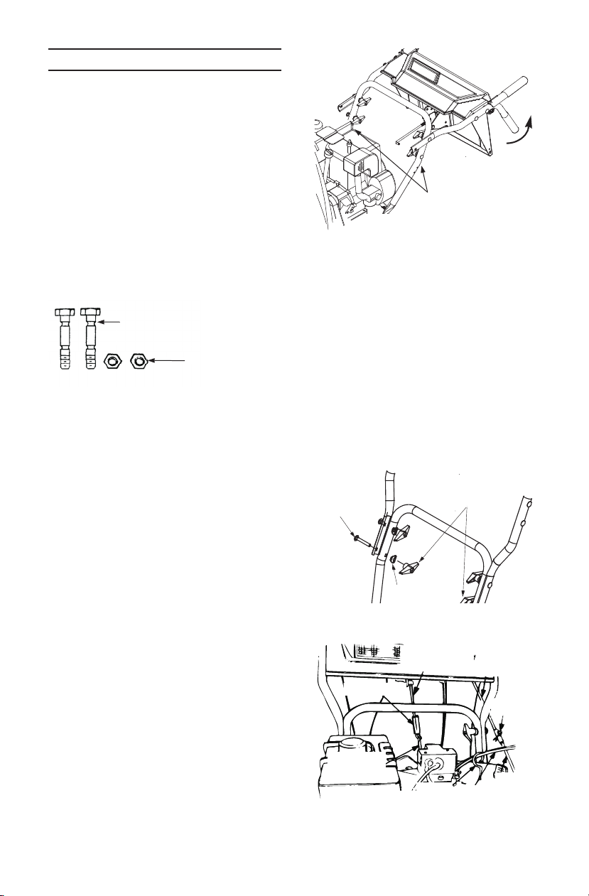
AUGER SHEAR BOLTS
The au gers are se cured to the spi ral
shaft with two shear bolts and hex
flange locknuts. Two re place ment hex
bolts and hex flange locknuts have
been pro vided for your con ve nience.
Store in a safe place un til needed.
Shear Bolts
5/16-18 x 1.75" Lg.
(710-0891)
Hex Flange
Locknuts
5/16-18 Thread
FIG URE 1
NOTE: Ref er ence to right hand or
left hand side of ma chine are ob served from the op er at ing po si tion.
IM POR TANT: Check the ad just ments
as in structed on page 10, and make
any fi nal ad just ments nec es sary
be fore op er at ing your snow thrower.
Fail ure to fol low the in struc tions may
cause dam age to the snow thrower.
• Re move sta ples or break glue on the
top flaps of the car ton. Re move any
loose parts in cluded with unit (i.e.,
owner’s man ual, etc.).
• Cut along dot ted lines and lay end of
car ton down flat. Re move pack ing ma te rial.
• Roll unit out of car ton. Check car ton
thor oughly for loose parts or lit er a ture.
• Re move the lower two plas tic wing
nuts, cupped wash ers and car riage
bolts from each side of the lower han dle. See Fig ure 2.
• Raise the up per han dle as sem bly un til it
locks over the lower han dle. See Fig ure
2 and 3.
(712-04063)
Wing Nuts,
Washers
and Bolts
FIG URE 2
• Se cure the up per han dle and lower
han dle with the two plas tic wing nuts,
cupped wash ers and car riage bolts pre vi ously re moved. See Fig ure 3.
• Slide the shift rod con nec tor down over
the end of the lower shift rod. See Fig ure 4. Tap the con nec tor un til it locks
on the lower shift rod.
NOTE: If the con nec tor is not prop erly as sem bled, the shift rod will
pivot and you will not be able to
shift gears or change di rec tions.
Carriage
Bolt
Wing Nuts
Washer
FIG URE 3
Upper Shift
Rod
Connector
Upper
Chute
Crank
Hairpin
Clip
Lower
Shift Rod
Cable
Guide
Chute
Cable
Lower
Chute
Crank
FIG URE 4
5
Page 6
• Re move the hair pin clip from the end of
the up per chute crank. Slide the up per
chute crank into the lower chute crank.
Align the holes, and se cure with hair pin
clip. See Fig ure 4.
• The ca ble ties nor mally are loosely in -
stalled on each side of the lower han dle
at the fac tory. Pull the ca ble ties tight to
se cure. Trim ex cess from the ends of
ca ble ties.
• If not al ready at tached, slip the ca bles
that run from the han dle panel to the
chute into the ca ble guide lo cated on
top of the en gine. See Fig ure 4.
FINAL ASSEMBLY AND ADJUSTMENTS
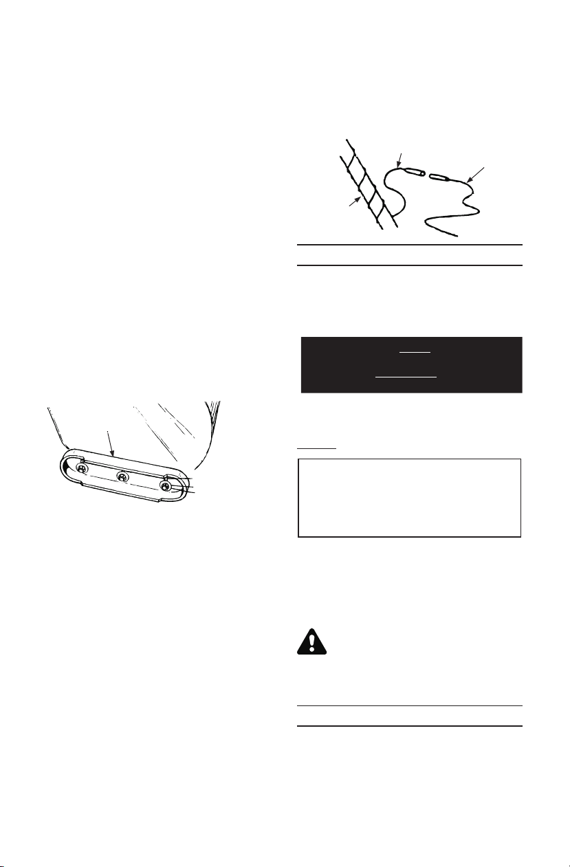
Slide Shoe Adjustment
The space be tween the shave plate and
the ground can be ad justed. For close
snow re moval, place slide shoes in the
low po si tion. Use mid dle or high po si tion when area to be cleared is un even.
See Fig ure 5.
LAMP WIRING CONNECTION
(optional)
• Wrap the wire from the lamp down the
right han dle un til the wire can be
plugged into the al ter na tor lead wire un der the fuel tank.
Lamp Wire
Al ter na tor
Lead
Right
Han dle
BE FORE STARTING
NOTE: The crank case has been
filled with oil and fac tory tested.
Paint on the muf fler may have burnt
due to test ing.
AT TEN TION: YOU MUST CHECK OIL
LEVEL BE FORE OP ER A TION. LEVEL
MUST BE AT FULL MARK ON DIP STICK
BE FORE ENGINE IS STARTED.
Slide
Shoe
High
Middle
Low
FIG URE 5
• Ad just slide shoes by loos en ing the hex
nuts, wash ers and car riage bolts and
mov ing slide shoes to de sired po si tion.
Make cer tain the en tire bot tom sur face
of slide shoe is against the ground to
avoid un even wear on the slide shoes.
Tighten bolts se curely.
CHUTE CLEAN-OUT TOOL
The chute clean-out tool is con ve niently
fas tened to the rear of the au ger hous ing with a mount ing clip. Use the
clean-out tool to clear snow and ice
which may lodge in the dis charge chute
dur ing op er a tion. Re fer to the Op er a tion
sec tion for more de tailed in for ma tion re gard ing the chute clean-out tool.
Fail ure to fol low this pro ce dure may re sult in se ri ous en gine dam age which
will not be cov ered by war ranty.
Your unit may be equipped with a
plas tic fuel plug at the open ing of the
fuel tank. Please re move and dis card
the plug be fore fill ing your unit with
gas or be fore putt ing the unit into
op er a tion.
GAS AND OIL FILL-UP
Ser vice the en gine with gas o line and oil
as in structed in the sep a rate en gine
man ual packed with your snowthrower.
Read in struc tions care fully.
WARNING: Never fill fuel tank
in doors. Never fill fuel tank with
en gine run ning or while en gine
is hot. Do not smoke when fill ing fuel tank.
OP ER A TION
TO START ENGINE
• Make cer tain the metal loop on the end
of the spark plug wire (in side the boot)
is fas tened se curely over the metal tip
on the spark plug. See Fig ure 6.
6
Page 7

• Make cer tain the au -
Disengaged
ger and drive clutch
le vers are in the dis en gaged (re leased)
po si tion.
• Move throt tle con trol
up to FAST po si tion. In sert ig ni tion
key into slot. See Fig ure 7. Be cer tain it
snaps into place. Do not turn key.
Elec tric Starter (Op tional)
WARNING: The op tional elec tric
starter is equipped with a
three-wire power cord and plug,
and is de signed to op er ate on
120 volt AC House hold cur rent.
It must be prop erly grounded at
all times to avoid the pos si bil ity
of elec tric shock which may be
in ju ri ous to the op er a tor.
Fol low all in struc tions care fully. De ter mine
that your house wir ing is a three wire
grounded sys tem. Ask a li censed elec tri cian if you are not cer tain. If your house
wir ing sys tem is not a three-wire grounded
sys tem, do not use this elec tric starter un der any con di tions. If your sys tem is
grounded and a three hole re cep ta cle is
not avail able at the point your starter will
nor mally be used, one should be in stalled
by a li censed elec tri cian.
When con nect ing the power cord, al ways con nect cord to starter on en gine
first, then plug the other end into a
three-hole grounded re cep ta cle.
When dis con nect ing the power cord, al ways un plug the end from the
three-hole grounded re cep ta cle first.
• Ro tate choke knob to FULL choke po si tion.
• Push primer but ton two or three times
as in structed in the sep a rate en gine
man ual. See Fig ure 7.
NOTE: Al ways cover vent hole in
primer but ton when push ing. Ad di tional prim ing may be nec es sary
for first start if tem per a ture is be low
15oF (-9oC).
• Con nect power cord to switch box on
en gine. Plug the other end of power
cord into a three-hole, grounded 120
volt AC re cep ta cle.
Metal
Loop on
Spark
Plug Wire
Rubber Boot
FIG URE 6
ENGINE WILL NOT START
UN LESS IG NI TION KEY IS
IN SERTED INTO IG NI TION
SLOT IN CAR BU RE TOR
COVER. DO NOT TURN
IG NI TION KEY.
Spark Plug
Switch Box
Starter
Button
Rope
Starter
Handle
Muffler
Primer
Ignition
Key
Choke
Throttle
Control
FIGURE 7 - Your engine may be slightly
different from the engine shown .
CHOKE OFF
• Push starter but ton to crank en gine. See
FULL CHOKE
Fig ure 7.
• When en gine starts, re lease starter but -
ton, and move choke grad u ally to OFF. If
en gine fal ters, move choke im me di ately
to FULL and then grad u ally to OFF.
Re coil Starter:
• Ro tate choke knob to FULL choke po si -
tion (cold en gine start).
If en gine is warm, place choke in OFF
po si tion in stead of FULL.
• Push primer but ton two or three times
as in structed in the sep a rate en gine
man ual. See Fig ure 7.
If en gine is warm, push primer but ton
once only.
7
Page 8

NOTE: Al ways cover vent hole in
primer but ton when push ing. Ad di tional prim ing may be nec es sary for
first start if tem per a ture is be low 15°F.
• Grasp starter han dle (see Fig ure 7) and
pull rope out slowly, un til it pulls slightly
harder. Let rope re wind slowly.
• Pull starter han dle rap idly. Do not al low
han dle to snap back. Al low it to re wind
slowly while keep ing a firm hold on the
starter han dle. Re peat un til en gine
starts.
• As en gine warms up and be gins to op -
er ate evenly, ro tate choke knob slowly
to OFF po si tion. If en gine fal ters, re turn
to FULL choke, then slowly move to
OFF po si tion.
TO STOP ENGINE
• Run en gine for a few min utes be fore
stop ping to help dry off any mois ture on
the en gine.
• To help pre vent pos si ble freeze-up of
starter, pro ceed as fol lows:
Op tional Elec tric Starter: Con nect
power cord to switch box on en gine,
then to 120 volt AC re cep ta cle. With the
en gine run ning, push starter but ton and
spin the starter for sev eral sec onds. The
un usual sound made by spin ning the
starter will not harm en gine or starter.
Dis con nect the power cord from re cep ta cle first, and then from switch box.
Re coil Starter: With en gine run ning,
pull starter rope with a rapid, con tin u ous full arm stroke three or four times.
Pulling the starter rope will pro duce a
loud clat ter ing sound, which is not
harm ful to the en gine or starter.
• To stop en gine, re move the ig ni tion key.
Do not turn key. Dis con nect the spark
plug wire from the spark plug to pre vent ac ci den tal start ing while equip ment
is un at tended.
NOTE: Do not lose ig ni tion key.
Keep it in a safe place. En gine will
not start with out the ig ni tion key.
• Wipe all snow and mois ture from the
car bu re tor cover in the area of the con trol le vers. Also, move con trol le vers
back and forth sev eral times.
CONTROLS
Con trol po si tions and in for ma tion mark ings, on your ma chine are in
in ter na tional sym bols, as ex plained.
Calls your at ten tion to in struc tions con cern ing per sonal safety.
AUGER CLUTCH GRIP
Lo cated on left hand han dle.
Squeeze to en gage. Re lease
to stop.
DRIVE CLUTCH GRIP
Located on right hand han dle. Squeeze to en gage. Re lease to stop.
Keep by stand ers, help ers,
pets and chil dren at least 75
feet from the ma chine while
it is in op er a tion.
Avoid in jury from ro tat ing au ger – keep hands, feet and
cloth ing away.
Never put hand in chute.
Contact with ro tat ing parts
can am pu tate fin gers and
hands. Use clean-out tool to
un clog dis charge chute.
TO ENGAGE DRIVE
• With the en gine run ning near top
speed, move shift le ver into one of the
pos si ble FOR WARD or RE VERSE po si tions. Se lect a speed ap pro pri ate for the
snow con di tions that ex ist. Use the
slower speeds un til you are fa mil iar with
the op er a tion of the snowthrower.
• Squeeze the left hand au ger clutch grip
and en gage it.
• While the left hand au ger clutch grip is
en gaged, en gage the right hand drive
clutch grip.
8
Page 9

• Re lease the left hand au ger clutch grip
only. The in ter lock mech a nism should
keep the left hand clutch en gaged un til
the right hand clutch is re leased.
NOTE: Never move shift le ver with out first re leas ing the drive clutch.
CHUTE CLEAN-OUT TOOL
WARNING: Stop the en gine by
re mov ing the ig ni tion key and
wait for ALL mov ing parts to
stop, be fore us ing the clean-out
tool.
The chute clean-out tool is con ve niently
fas tened to the rear of the au ger hous ing with a mount ing clip. Should snow
and ice lodge it self in the dis charge
chute dur ing op er a tion, pro ceed as fol lows to safely clean the chute and
chute open ing:
• Re lease both au ger and drive clutch
grips.
• Stop the en gine by re mov ing the ig ni -
tion key.
• Re move the clean-out tool from the clip
which se cures it to the rear of the au ger
hous ing.
• Use the shovel-shaped end of the
clean-out tool to dis lodge and scoop
any snow and ice which has formed in
and near the dis charge chute.
WARNING: Never use your
hands to clean snow and ice
from the dis charge chute or au ger hous ing.
• Refasten the clean-out tool to the
mount ing clip on the rear of the au ger
hous ing, re in sert the ig ni tion key and
start the snow thrower’s en gine.
• While stand ing in the op er a tor’s po si -
tion (be hind the snow thrower), en gage
the au ger clutch le ver for a few sec onds
to clear any re main ing snow and ice
from the dis charge chute.
TRIGGER LEVERS (optional)
The trig ger le vers are lo cated on the
un der side of the han dles and used to
steer your snowthrower. See Fig ure 8.
To turn right, squeeze the right trig ger
le ver and guide the snowthrower to the
Trigger Assembly
FIGURE 8
right. Squeeze and guide the left le ver
to turn left. These con trols should be
used while op er at ing your snowthrower
in open ar eas un til you be come fa mil iar
with their op er a tion.
Squeeze both trig gers to free wheel or
to trans port unit.
TIRE PRESSURE
Pneu matic tires only. Tires are over-in flated for ship ping pur poses. Cor rect
tire pres sure is 10-15 psi.
OPERATING TIPS
NOTE: Al low the en gine to warm
up for a few min utes as the en gine
will not de velop full power un til it
reaches op er at ing tem per a ture.
WARNING: Tem per a ture of muf fler and sur round ing ar eas may
ex ceed 150°F. Avoid these ar eas.
• For most ef fi cient snow re moval, re -
move snow im me di ately af ter it falls.
• Dis charge snow down wind when ever
pos si ble. The dis tance snow is thrown
can be ad justed by ad just ing the an gle
of the chute as sem bly. The sharper the
an gle, the shorter the dis tance snow is
thrown. Slightly over lap each pre vi ous
swath.
• Set the slide shoes 1/4" be low the
scraper bar for nor mal us age. The slide
shoes may be ad justed up ward for
hard-packed snow. Ad just down ward
when us ing on gravel or crushed rock.
• Be cer tain to fol low the pre cau tions
listed un der pre vi ous sec tion, “To Stop
En gine” to pre vent pos si ble freeze up.
• Clean the snowthrower thor oughly af ter
each use.
9
Page 10

ADJUSTMENTS
WARNING: NEVER at tempt to
clean chute or make any ad just ments while en gine is run ning.
REMOTE CHUTE ASSEMBLY
ADJUSTMENT
The re mote chute con trol ca bles have
been pre-ad justed at the fac tory. Move
the re mote chute le ver on the con trol
panel back and for ward to ad just an gle
of the chute as sem bly.
CARBURETOR ADJUSTMENT
Mi nor car bu re tor ad just ment may be
re quired to com pen sate for dif fer ences in fuel, tem per a ture, al ti tude
and load.
Re fer to the sep a rate en gine man ual
packed with your unit for car bu re tor ad just ment in for ma tion.
NOTE: Fail ure to com ply with sug gested main te nance and lu bri ca tion
spec i fi ca tions will void war ranty.
CHECK ADJUSTMENT OF CLUTCH
CABLES
Proper ad just ment is achieved by slid ing
the spring up the ca ble and thread ing
the nut in or out. Cor rect ad just ment on
ca bles is min i mal slack but not tight.
AUGER BELT ADJUSTMENT
Pe ri odic ad just ment of the belt ten sion
may be re quired due to nor mal stretch
and wear on the belt. In crease belt ten sion if the au gers hes i tate while the
au gers are en gaged or de crease ten sion
if the the au gers con tinue to turn when
the au gers are dis en gaged. To ad just,
dis con nect fer rule from the brake
bracket as sem bly (Fig ure 16) and thread
fer rule in (to wards idler) to in crease ten sion on belt, out to de crease ten sion.
SHIFT ROD ADJUSTMENT
• To ad just the shift rod, re move the cot ter
pin which se cures the fer rule to the shift
le ver.
• Place the shift le ver in the fast est for -
ward po si tion. Push the shift rod down
Ferrule
Flat Washer
Cot ter Pin
Upper
Shift Rod
FIGURE 9
sharply, as far as it will go, to put the
drive into the fast est for ward po si tion.
Thread the fer rule in or out on the shift
rod as nec es sary un til the fer rule lines
up with the up per hole in the shift le ver.
In sert fer rule from the right side of the
snowthrower into up per hole in shift le ver and se cure with flat washer and
in ter nal cot ter pin. See Fig ure 9.
SLIDE SHOE ADJUSTMENT
The space be tween the shave plate and
the ground can be ad justed. Re fer to
“Fi nal As sem bly and Ad just ment".
LUBRICATION
WHEELS
Oil or spray lu bri cant into bear ings at
wheels at least once a sea son. Re move
wheels, clean and coat ax les with a
multi-pur pose au to mo tive grease.
CHAINS AND SHIFTING MECHANISM
Re move rear cover. Oil all chains.
sprock ets, bear ings, the hex ag o nal
shaft, round shaft and shift ing mech a nism at least once a sea son. Use
en gine oil or a spray lu bri cant. Avoid
get ting oil on rub ber fric tion wheel and
alu mi num drive plate.
CHUTE CRANK WORM
The worm gear on the chute di rec tion
crank should be greased with multi-pur pose au to mo tive grease.
AUGER SHAFT
Re move au ger bolts on au ger shaft, see
See Fig ure 11. Oil or spray lu bri cant in side shaft.
10
Page 11

ENGINE
Re fer to en gine man ual for en gine lu bri ca tion in struc tions.
WARNING: When fol low ing in struc tions in sep a rate en gine
man ual for drain ing oil, be sure
to pro tect frame to avoid oil
drip ping onto trans mis sion
parts.
HEX SHAFT
Lu bri cate the gear (hex) shaft with a light
weight cold weather lu bri cant at lease
once a sea son or af ter ev ery 25 hours of
op er a tion.
IM POR TANT: Keep all grease and oil off
of the rub ber fric tion wheel and alu mi num
drive plate.
If for any rea son your trans mis sion was
dis as sem bled and the au ger ca ble dis con nected, re as sem ble rout ing the ca ble
so it does not in ter fere with any mov ing
parts when pulled tight.
MAIN TE NANCE and
LU BRI CA TION
CHECK LIST
Check en gine oil level • •
Change en gine oil • •
Tighten all screws and nuts •
Check spark plug •
Lu bri cate chute open ing •
Lu bri cate wheel axle •
Lu bri cate wheel bear ings •
Lu bri cate chains, bear ings, • •
and hex shaft
Check wear on fric tion wheel
rub ber •
Check au ger pul ley(s) and
au ger drive belts •
no saeS hcaE gni nni geB
sruoH 2 tsriF re tfA
sruoH 5 re tfA
yltneu qerF
eg arotS ero feB
MAINTENANCE
WARNING: Dis con nect the
spark plug wire and ground
against the en gine be fore per form ing any re pairs or main te nance
AUGERS
The au gers are se cured to the spi ral shaft
with two shear bolts and hex locknuts.
See Fig ure 11. If you hit a for eign ob ject
or ice jam, the snowthrower is de signed
so that the shear bolts will shear.
If the au gers will not turn, check to see if
the hex bolts have sheared. Two re place ment hex bolts and hex lock nuts have
been pro vided with the snowthrower.
When re plac ing bolts, spray an oil lu bri cant into shaft be fore in sert ing new bolts.
SHAVE PLATE AND SLIDE SHOES
The shave plate and slide shoes on the
bot tom of the snowthrower are sub ject to
wear. They should be checked pe ri od i cally and re placed when nec es sary.
Shift Arm
Au ger
Bracket
As sem bly
Drive
Bracket
Hex Bolt
and
Cupped
Washer
Hex
Shaft
Fric tion
Wheel
FIG URE 10
NOTE: Some mod els are equipped
with re vers ible slide shoes.
To re move slide shoes, re move the
car riage bolts, cupped wash ers and hex
nuts which at tach them to the
snowthrower. Re as sem ble new slide
shoes with the car riage bolts, cupped
wash ers (cupped side goes against
slide shoes) and hex nuts.
11
Page 12

Au ger
Shaft
Hex Shear
Bolt
Dis charge
Chute
As sem bly
Hex Cap
Screw
Shave Plate
Hex Centre Locknut
FIGURE 11
To re move shave plate, re move slide
shoes as pre vi ously in structed, re move
the car riage bolts, cupped wash ers
and hex nuts which at tach it to the
snowthrower hous ing. Re as sem ble new
shave plate, mak ing sure heads of the
car riage bolts are to the in side of the
hous ing. Tighten se curely.
BELT RE MOVAL AND RE PLACE MENT
WARNING: Re move the spark
plug wire from the spark plug
and ground. Drain gas o line
from the fuel tank, or place a
piece of plas tic film un der neath
the gas cap to pre vent gas o line
from leak ing.
Auger Drive Belt
To re move and re place ei ther the au ger
drive belt or the drive belt, pro ceed with
the fol low ing in struc tions.
• Dis con nect chute crank as sem bly at the
dis charge chute by re mov ing the cot ter
pin and flat washer. See Fig ure 12.
Flat Washer
Chute
Crank
Plastic
Bushing
Hex
Locknut
Chute Flange
FIG URE 13
Keeper
Belt
Cover
Self-Tapping Screw
Flat Washer
FIG URE 14
• Re move the chute as sem bly by
removing the hex cap screws, chute
flange keep ers and hex locknuts. See
Fig ure 13.
• Re move the plas tic belt cover on the
front of the en gine by re mov ing three
self-tap ping screws and flat wash ers.
See Fig ure 14.
En gine
Pul ley
Large
Shoul der
Bolt
Cotter Pin
Chute Crank
Bracket
FIGURE 12
Hex Nuts
FIG URE 15
12
Page 13

• Re move the large shoul der bolt and
washer on the left hand side of the en gine pul ley with an ad just able wrench.
See Fig ure 15.
NOTE: Ref er ence to right hand or
left hand side of ma chine are ob served from the op er at ing po si tion.
• Re move the cot ter pin and washer from
the fer rule in or der to dis con nect the
au ger idler rod from the brake bracket
as sem bly as shown in Fig ure 16.
FIG URE 17
Frame
As sem bly
Au ger
Housing
Re move
Screw
and Lock
Washer
Au ger
Idler
Rod
Fer rule
Cotter
Pin and
Brake
Washer
Bracket
As sem bly
“Z”
Fitting
Ca ble Roller Guide
FIG URE 16
• Slip the au ger drive belt (the front belt)
off the en gine pul ley. See Fig ure 18.
• Pull the brake bracket as sem bly to -
wards the ca ble guide roller and
un hook the au ger ca ble “Z” fit ting. See
Fig ure 16.
• Re move the top screws and
lockwashers which at tach the au ger
hous ing as sem bly to the frame as sem bly. A 9/16" wrench is re quired. See
Fig ure 17.
• Sep a rate the au ger hous ing from the
frame as sem bly by tilt ing the hous ing
for ward and pull ing up the han dles.
• Rest the han dle as sem bly on the
ground and tip the re main ing half for ward to rest on the hous ing.
Brake Bracket
As sem bly
Au ger Drive
Belt
Pul ley
Auger Pulley
Mounting
Bolt
Belt Keeper (5)
Lockwasher (5)
FIG URE 18
To Re move the Au ger Drive Belt:
a. Using a 9/16" wrench re move the five
belt keep ers and lockwashers from
around the au ger pul ley. See Fig ure 18.
b. Re move and re place au ger drive
belt.
c. Re place lockwashers and belt keep ers.
NOTE: The au ger pul ley mount ing
bolt has chem i cal patch which sets
af ter bolt is as sem bled. If the bolt
is re moved for any rea son it must
be re placed.
NOTE: The brake puck in the brake
bracket as sem bly must al ways be
firmly seated in the pul ley groove
when the au ger clutch le ver is in
the dis en gaged po si tion.
13
Page 14

Belt Cover
1
2
3
4
Support
Bracket
Idler
Pulley
Drive
Belt
FIG URE 19
NOTE: See Ad just ment sec tion for
"Au ger Belt Ad just ment".
To Remove the Drive Belt:
a. Pull idler pul ley away from belt. See
Fig ure 19.
b. Re move drive belt from the en gine
pul ley and bot tom drive pul ley.
c. Re place belt and re as sem ble in re -
verse or der.
• Re as sem ble the two halves of the unit
hook ing the lower por tion of the au ger
hous ing over the sta tion ary shoul der
bolts in the frame as sem bly.
• Se cure the two halves with the two
screws and lockwashers.
• At tach the “Z” fit ting of the ca ble into
the brake bracket as sem bly. See Fig ure
16.
• Slip the au ger drive belt over en gine
pul ley.
• In sert fer rule on au ger idler rod into
bracket bracket as sem bly and se cure with
flat washer and cot ter pin.
• Re as sem ble the large shoul der bolt and
lockwasher as shown in Fig ure 15.
• Re as sem ble belt cover, chute as sem bly
and chute crank.
Changing the Friction Wheel
The rub ber on the fric tion wheel is sub ject to wear and should be checked
af ter 25 hours of op er a tion, and pe ri od i cally there af ter. Re place the fric tion
wheel rub ber if any signs of wear or
crack ing are found.
Bonded fric tion
wheel rub ber
Hex
self-tap ping
screws
FIG URE 20
Pin
Shift Rod
As sem bly
Fric tion
Spacer
Sprocket
Wheel
Shaft
Sup port Bracket
FIG URE 21
• Drain the gas o line from the
snowthrower, or place a piece of plas tic
un der the gas cap.
• Tip the snowthrower up and for ward, so
that it rests on the hous ing.
• Re move six self-tap ping screws from
the frame cover un der neath the
snowthrower and re move cover.
• Re move the wheels from the axle.
• Using a 7/8" wrench hold the hex shaft
and re move the hex bolt and cupped
washer and bear ing from left side of the
frame. See Fig ure 10. Hold the fric tion
wheel as sem bly, and slide the hex shaft
out of the unit to ward the right hand
side.
• Re move the four screws from the fric -
tion wheel as sem bly and re move the
bonded fric tion wheel.
• Re as sem ble new bonded fric tion wheel
rub ber to the fric tion wheel as sem bly,
turn each screw ap prox i mately 2 turns
in or der shown in Figure 20 un til screws
are tight. It is im por tant for the rub ber
to be as sem bled sym met ri cally.
14
Page 15

• Po si tion the fric tion wheel as sem bly up
onto the pin of the shift rod as sem bly
and slide the shaft through the fric tion
wheel. See Fig ure 21.
• Slide the hex shaft into the hex I.D. of
the sprocket, the spacer and the left
ball bear ing and se cure with the
cupped washer and hex bolt.
• Re move plas tic film from gas cap.
NOTE: Make sure the pin from the
shift arm as sem bly is as sem bled to
the new fric tion wheel as sem bly.
CAUTION: Check engine and
snowthrower frequently for loose
nuts, bolts, etc. and keep these items
tightened.
STORAGE INSTRUCTIONS
NEVER STORE ENGINE WITH
FUEL IN TANK IN DOORS OR IN
EN CLOSED, POORLY VEN TI LATED EN CLO SURES, WHERE
FUEL FUMES MAY REACH AN
OPEN FLAME OR SPARK.
If unit is to be stored over 30 days, pre pare for stor age as in structed in the
sep a rate en gine man ual packed with
your unit.
NOTE: Fail ure to com ply with sug gested main te nance and
lu bri ca tion spec i fi ca tions will void
war ranty.
15
Page 16

TROU BLE SHOOTING
PROB LEM POS SI BLE CAUSE(S) COR REC TIVE AC TION
En gine fails to start 1. Fuel tank empty, or stale fuel.
2. Blocked fuel line.
3. Choke not in the FULL po si tion.
4. Faulty spark plug.
5. Safety key not in ig ni tion switch
on en gine.
6. Spark plug wire dis con nected.
7. Primer but ton not be ing used
prop erly.
8. Fuel shut-off valve closed.
En gine runs er ratic 1. Unit run ning on CHOKE.
2. Blocked fuel line or stale fuel.
3. Wa ter or dirt in the fuel sys tem.
Loss of power 1. Spark plug wire loose.
2. Gas cap vent hole plugged.
Ex ces sive vi bra tion 1. Loose parts or dam aged au ger. 1. Stop the en gine im me di ately and dis -
Unit fails to drive prop erly 1. Drive con trol ca ble in need of
Unit fails to
dis charge snow
Heated grips are not
cre at ing heat
ad just ment.
2. Drive belt loose or dam aged.
1. Dis charge chute clogged.
2. Shear bolt sheared.
3. For eign ob ject lodged in au ger.
4. Au ger con trol ca ble in need of
ad just ment.
5. Au ger belt loose or dam aged.
1. Unit is not run ning.
2. Loosen elec tri cal con nec tions.
3. Blown Fuse.
4. Faulty grip. If one heated grip
fails, both grips will not func tion.
1. Fill tank with clean, fresh gas o line.
Fuel be comes stale af ter thirty days.
2. Clean the fuel line.
3. Move switch to the FULL po si tion.
4. Clean, ad just gap or re place.
5. In sert the key fully into the switch.
6. Con nect spark plug wire.
7. Re fer to the en gine man ual.
8. Open fuel shut-off valve.
1. Move the choke le ver to OFF po si tion.
2. Clean the fuel line; fill the tank with
clean, fresh gas o line.
3. Drain the fuel tank and car bu re tor.
Re fill with fresh fuel.
1. Con nect and tighten spark plug wire.
2. Re move ice and snow from gas cap.
Be cer tain vent hole is clear.
con nect the spark plug wire. Tighten
all bolts and nuts. If vi bra tion con tin ues, have the unit ser viced by an
au tho rized ser vice dealer.
1. Ad just drive con trol ca ble. Re fer to
Ad just ment Sec tion of this man ual.
2. Re place drive belt. Re fer to Belt Re moval and Re place ment.
1. Stop en gine and dis con nect spark
plug wire. Clean dis charge chute and
in side of au ger hous ing with tool pro vided.
2. Re place shear bolt.
3. Stop en gine im me di ately and dis con nect spark plug wire. Re move ob ject
from au ger.
4. Ad just au ger con trol ca ble. Re fer to
Ad just ment sec tion of this man ual.
5. Re fer to Belt Re moval and Re place ment.
1. Start the unit
2. Un der the han dle panel, check con nec tions from the han dles to the
wir ing har ness.
3. Re place 5A fuse un der the han dle
panel near crank switch con nec tor.
4. Have the grips checked at an au tho rized ser vice dealer.
16
Page 17

THREE (3) YEAR LIMITED WAR RANTY
For three (3) years from the date of orig i nal pur chase of our prod ucts, we will ei ther re pair or
re place, at its op tion, free of charge, F.O.B. Fac tory or au tho rized ser vice firm, any part found to
be DE FEC TIVE IN MA TE RIAL and WORK MAN SHIP for the orig i nal pur chaser. all trans por ta tion
charges on parts sub mit ted for re place ment un der this war ranty must be paid by the pur chaser
un less re turn is re quested by the man u fac turer.
This war ranty DOES NOT ap ply to any part which has be come in op er a tive through mis use, ex ces sive use, ac ci dent, ne glect, im proper main te nance or al ter ations by un au tho rized per sons.
The lim ited war ranty does not ex tend to the re place ment of parts which are not de fec tive, but
where reg u lar us age has ex hausted the life of the part.
EN GINES, ELEC TRIC START KITS, PEER LESS TRANS MIS SIONS AND PEER LESS
TRANSAXLES ARE WAR RANTED BY THEIR RE SPEC TIVE MAN U FAC TURER. ALL CLAIMS
AGAINST THESE COM PO NENTS MUST BE HAN DLED THROUGH THE RE SPEC TIVE MAN U FAC TURER’S SER VICE DEAL ERS.
Belts, light bulbs, clutch parts (fric tion wheels), grass bags, tires, seats, rider deck wheels and
cut ting blades are cov ered by a 60 day lim ited war ranty.
Bat ter ies are cov ered by a 90 day lim ited war ranty.
Fuses, shear bolts and blade adapt ers are con sid ered con sum able items and as such are not
war ranted.
NOTE: Reg u lar main te nance re place ment parts and re lated in spec tions and ad just ments are
ex cluded from cov er age when made as part of nor mal main te nance ser vice.
TRAC TOR AT TACH MENT WAR RANTY
Mower decks in cluded with your prod uct, or sold sep a rately, as an at tach ment for your gar den
trac tors will be war ranted ac cord ing to the above terms of the man u fac turer three (3) year lim ited con sumer war ranty.
ALL OTHER AT TACH MENTS will be sold un der the same con di tion as above ex cept the war ranty will be ONE YEAR FROM DATE OF ORIG I NAL PUR CHASE.
PER SONAL USE
THE FORE GO ING PARA GRAPHS CON STI TUTE THE MAN U FAC TURER’S EN TIRE WAR RANTY WITH RE SPECT TO ANY PROD UCT PUR CHASED AND USED FOR PER SONAL
FAM ILY, HOUSE HOLD/RES I DEN TIAL PUR POSES, AS DIS TIN GUISHED FROM COM MER CIAL US AGE.
COM MER CIAL USE
ALL AP PLI CA TIONS OTHER THAN PER SONAL USE AS OUT LINED ABOVE, ARE CON SID ERED COM MER CIAL US AGE.
New prod ucts pur chased for com mer cial us age are war ranted in the same man ner and
to the same ex tend EX CEPT the term of war ranty will be 60 DAYS from date of pur chase,
90 days if your unit is equipped with an OHV en gine. “
WAR RANTY SER VICE CAN ONLY BE PER FORMED BY AN AU THO RIZED SER VICE
DEALER. ANY NON-ORIG I NAL EQUIP MENT RE PLACE MENT PART USED ON OR IN A
PROD UCT UN DER WAR RANTY WILL BE EX CLUDED FROM THAT WAR RANTY COV ER AGE,
AS WILL BE ANY RE LATED DAM AGED COM PO NENTS RE SULT ING FROM THE IN STAL LA TION OF A RE PLACE MENT PART FROM AN OTHER SOURCE OTHER THAN THE
MAN U FAC TURER.
17
Page 18

SUP PLE MENT SUP PLÉ MENT
IN STRUC TIONS FOR AT TACH ING
THE CHUTE AS SEM BLY
• Place chute as sem bly over chute
open ing, with the open ing in the
chute as sem bly fac ing the front of the
unit. Place chute flange keep ers be neath lip of chute as sem bly, with the
flat side of chute flange keeper fac ing
down ward.
• In sert hex cap screws up through
chute flange keeper and chute as sem bly as shown in Fig ure 1. Se cure
with hex flange locknuts. Tighten with
two 7/16" wrenches. Do not over
tighten.
• With the hex nuts loos ened on the
lower chute crank bracket (see Fig ure
2) ad just the bracket so that the spi ral
on the chute crank fully en gages the
teeth on the chute as sem bly. Tighten
the nuts on the lower chute crank
bracket se curely.
FIG URE 1
Flat Washer
Cotter Pin
Chute Crank
Bracket
FIGURE 2
Dis charge Chute
As sem bly
Hex Cap
Screw
(710-3015)
Hex Flange
Locknut
(712-3027)
Chute Flange
Keeper (731-0851A)
Chute
Crank
Plastic
Bushing
Hex Nuts
MONTAGE DE LA GOULOTTE
• Disposez la goulotte au-dessus de
l’ouverture en plaçant l’ouverture
d’éjection de la goulotte face à l’avant
de la ma chine. Positionnez les
garde-brides sous le rebord de la
goulotte, le côté plat des garde-brides
tourné vers le bas.
• Faites passer les vis à cha peau à tête
hex. à travers les garde-brides et la
goulotte, comme à la Fig ure 1.
Maintenez en place avec des
contre-écrous à embase. Serrez avec
deux clés de 7/16 po. Ne serrez pas
excessivement.
• Les écrous à six pans du sup port de
la manivelle de la goulotte étant
desserés, et ajustez celui-ci (voir la
Fig ure 2) de manière que la partie
hélicoïdale de la manivelle s’engrène
bien avec les dents de la goulotte.
Serrez les écrous sur les sup port de
la manivelle inférieure.
Garde-bride de la goulotte
(731-0851A)
FIGURE 1
Rondelle plate
Goupille
fendue
Support de la manivelle de
la goulotte
FIGURE 2
Assemblage de
la goulotte
Vis à chapeau
à tête hex.
(710-3015)
Contre-écrou à
embase
(712-3027)
Coussinet en
plastique
Manivelle de la
goulotte
Écrous à
six pans
OGST-3105A
6.25.04
1
Page 19

SUP PLE MENT
 Loading...