

Page 1

Professional Shop Manual
P71 Series Vertical Shaft Engines
NOTE: These materials are for use by trained technicians who are experi enced in the service and repair of outdo or power
equipment of the kind described in this publication, and are not intende d for use by untrained or in experienced indi viduals.
These materials are intended to provide supplemental information to assist the trained technician. Untrained or inexperienced individuals should seek the assistance of an experie nced and trained professio nal. Read, understand, and follow all
instructions and use common sense when working on powe r e quip ment. T his includes the contents of the product’s Operators Manual, supplied with the equipment. No liability can be accepted for any inaccuracies or omission in this publication,
although care has been taken to make it as complete and accura te as possible at the time of publ ication. However , due to
the variety of outdoor power equipment and continuing product changes that occur over time, updates will be made to these
instructions from time to time. Therefore, it may be necessary to obtain the latest materials before servicing or repairing a
product. The company reserves the right to make changes at any time to this publication without prior notice and without
incurring an obligation to make such changes to previously published versions. Instructions, photographs and illustrations
used in this publication are for reference use only and may not depict actual model and component parts.
© Copyright 2013 MTD Products Inc. All Rights Reserved
MTD Products Inc. - Product Training and Education Department
Page 2

Page 3

Table of Contents
Chapter 1: Introduction
Professional Service Manual Intent .................................................................. 1
Safety ................................................................................................................1
Fasteners ..........................................................................................................3
Assembly instructions....................................................................................... 3
Model and serial number ..................................................................................5
Maintenance .....................................................................................................5
Spark plugs....................................................................................................... 6
Air filter.............................................................................................................. 7
Oil type and capacity......................................................................................... 8
Changing the oil ..............................................................................................10
Fuel system ..................................................................................................... 12
Servicing the fuel system................................................................................ 12
Fuel filter .........................................................................................................12
Valve lash .......................................................................................................13
Exhaust system ............................................................................................... 15
Cleaning the engine ........................................................................................15
General torque specifications ......................................................................... 15
Chapter 2: Basic Troubleshooting
Definitions .......................................................................................................17
Introduction .....................................................................................................17
Steps to troubleshooting ................................................................................. 17
Define the problem .......................................................................................... 17
Identify factors that could cause the problem ................................................. 19
Repairing the problem ..................................................................................... 23
Prime test ........................................................................................................ 24
Leak-down test ................................................................................................ 24
Compression test ............................................................................................26
PCV testing .....................................................................................................27
Troubleshooting flow charts ............................................................................28
Chapter 3: Air Intake System
Air filter............................................................................................................ 33
Carburetor removal/replacement .................................................................... 34
Intake manifold ................................................................................................ 36
I
Page 4

Chapter 4: The Fuel System and Governor
Fuel Line .........................................................................................................37
Inspect the fuel lines ....................................................................................... 37
Inspecting the fuel ........................................................................................... 38
Test fuel for alcohol ......................................................................................... 38
Fuel filter .........................................................................................................39
The fuel tank ................................................................................................... 40
Evaporative (EVAP) emissions system ...........................................................41
Troubleshooting the EVAP system ................................................................. 42
Autochoke .......................................................................................................43
Temperature compensator .............................................................................. 44
Carburetors .....................................................................................................45
Inspecting the carburetor ................................................................................ 45
Disassembly and rebuilding the carburetor ..................................................... 46
Governor .........................................................................................................48
Governor shaft ................................................................................................ 51
Governor cup, gear and oil slinger.................................................................. 53
Chapter 5: Lubrication
Oil type and quantity ....................................................................................... 55
Oil dipstick ....................................................................................................... 56
Dip stick tube removal ..................................................................................... 56
Lubrication system.......................................................................................... 57
PCV ................................................................................................................. 58
Chapter 6: Starters
Engine shroud removal ...................................................................................61
Recoil starter removal/replacement ................................................................ 62
Starter Cup ...................................................................................................... 63
Starter Rope .................................................................................................... 64
Starter pulley and recoil spring ....................................................................... 66
Electric starter .................................................................................................68
Starter Interlock Switch ...................................................................................69
Schematic .......................................................................................................70
Chapter 7: Ignition System
Troubleshooting the ignition system ............................................................... 71
Troubleshooting the stop switch ..................................................................... 72
To test the stop switch.................................................................................... 72
Troubleshooting the flywheel .......................................................................... 73
Spark plug ....................................................................................................... 74
Cleaning the spark plug .................................................................................. 74
Inspection of the spark plug............................................................................ 74
Spark plug removal .........................................................................................74
Ignition module................................................................................................ 75
Module removal .............................................................................................. 75
Installing the module and setting the air gap .................................................. 75
Engine brake and stop switch (if equipped) .................................................... 76
Flywheel.......................................................................................................... 77
II
Page 5

Chapter 8: Exhaust
Muffler............................................................................................................. 79
Exhaust manifold ............................................................................................ 80
Chapter 9: Cylinder Head
Cylinder Head Removal...................................................................................81
Valves .............................................................................................................84
Push rod guides ..............................................................................................86
Chapter 10: Crankshaft, piston and Connecting Rod
Engine Dis-assembly ....................................................................................... 87
Crank shaft inspection ....................................................................................91
Piston Inspection ............................................................................................. 92
Connecting rod inspection .............................................................................. 94
Cylinder inspection.......................................................................................... 95
Bearings ..........................................................................................................96
Reassembly.................................................................................................... 97
Engine specifications chart ...........................................................................101
Engine torque values chart ........................................................................... 102
Chapter 11: Failure Analysis
Abrasive Ingestion ........................................................................................105
Insufficient lubrication ................................................................................... 108
Engine Over-speed .......................................................................................110
Overheated ...................................................................................................111
Mechanical Breakage/ Wear......................................................................... 112
Detonation/pre-ignition.................................................................................. 112
III
Page 6

IV
Page 7

Introduction
Caution is used to point out potential danger to the technician, operator, bystanders, or surrounding property.
! CA UTION! CA UTION
Warning indicates a potentially hazardous situation that, if not avoided, could result in death
or serious injury.
! WA RNI NG! WA RNI NG
! DANGER! DANGER
Danger indicates an imminently hazardous situation that, if not avoided, will result in death or
serious injury. This signal word is to be limited to the most extreme situations
CHAPTER 1: INTRODUCTION
Professional Service Manual Intent
This manual is intended to provide service dealers with an introduction to proven diagnostic and repair proce-
dures for MTD P71 series vertical shaft engines.
Disclaimer: The information contained in this manual is correct at the time of writin g. Both the prod u ct an d th e inf or -
mation about the product are subject to change without notice.
About the text format:
NOTE: Is used to point out information that is relevant to the procedure, but does not fit as a step in the proce-
dure.
• Bullet points: indicate sub-steps or points.
1. Numbered steps
1a. Sub-steps
the actions required to complete a step.
Disclaimer: This manual is intended for use by trained, professional technicians.
• Common sense in operation and safety is assumed.
• In no event shall MTD be liable for poor text interpretation or poor execution of the pro cedures described
in the text.
• If the person using this manual is uncomfortable with any procedures they encounter, they should seek
the help of a qualified technician or MTD Technical Support.
Safety
This Service Manual is meant to be used along with the Operator’s Manual. Read the Operator’s Manual and
familiarize yourself with the safety and operational instructions for the equipment being worked on. Keep a copy of
the Operator’s Manual for quick reference. Operator’s manuals may be viewed for free at the brand support website.
It will be necessary to have the complete model and serial number for the equipment.
indicate specific things that should be done, and the orde r in whic h th ey sh ou ld be do ne.
will be lettered and nested within steps. T wo or more sub-steps may be combined to describe
1
Page 8

P71 Series Vertical Shaft Engines
• Be prepared in case of emergency:
Keep a fire extinguisher nearby
Keep a first aid kit nearby
Keep emergency contact numbers handy
• Replace any missing or damaged safety labels on shop equipment.
• Replace any missing or damaged safety labels on equipment being serviced.
! CAUTION! CAUTION
• Grooming and attire:
Do not wear loose fitting clothing that may become entangled in equipment.
Long hair should be secured to prevent entanglement in equipment.
Jewelry is best removed.
• Protective gear: includes, but is not limited to
Clear eye protection ................................ while working around any machinery
Protective gloves ..................................... where necessary
Armored footwear.................................... when working around any machinery
Hearing protection ................................... in noisy environments
Chemically resistant gloves..................... when working with chemicals or solvents
Respirator................................................ when working with chemical or solvents
Appropriate tinted eye protection............. when cutting or welding
Flame resistant headgear, jacket, chaps. when cutting or welding
! WARNING! WARNING
! CAUTION! CAUTION
• Remember that some hazards have a cumulative effect. A single exposure may
cause little or no harm, but continual or repeated exposure may cause very serious
harm.
• Clean spills and fix obviously dangerous conditions as soon as they are noticed.
• Lift and support heavy objects safely and securely.
• Be aware of your surroundings and potential hazards that are inherent to all power
equipment. All the labels in the world cannot protect a technician from an instant of
carelessness.
• Exhaust fumes from running engines contain carbon monoxide (CO). Carbon
monoxide is a colorless odorless gas that is fatal if inhaled in sufficient quantity.
Only run engines in well ventilated areas. If running engines indoors, use an
exhaust evacuation system with adequate make-up air ventilated into the shop.
! DANGER! DANGER
2
Page 9

Introduction
Fasteners
• Most of the fasteners used on the MTD engine are metric. Some are fractional inches. For this reason,
wrench sizes are frequently identified in the text, and measurements are given in U.S. and metric scales.
• If a fastener has a locking feature that has worn, replace the fastener or apply a small amount of releasable thread locking compound such as Loctite® 242 (blue).
• Some fasteners, like cotter pins, are single-use items that are not to be reused. Other fasteners such as
lock washers, retaining rings, and internal cotter pins (hairpin clips) may be reused if they do not show
signs of wear or damage. This manual leaves that decision to the judgment of the technician.
Assembly instructions
• Torque specifications may be noted in the part of the text that covers assembly. They may be summa-
rized in tables along with special instructions regarding locking or lubrication. Whichever method is more
appropriate will be used. In many cases, both will be used so that the manual is handy as a quick-reference guide as well as a step-by-step procedure guide that does not require the user to hunt for information.
• Lubricant quantity and specification may be noted in the part of the text that covers maintenance, and
again in the section that covers assembly. They may also be summarized in tables along with special
instructions. Whichever method is more appropriate will be used. In many cases, the information will be
found in several places in the manual so that the manual is handy as a quick-r eference g uide as we ll as a
step-by-step procedure guide that does not require the user to hunt for information.
• The level of assembly instructions provided will be determined by the complexity of reassembly, and by
the potential for damage or unsafe conditions to arise from mistakes made in assembly.
• Some instructions may refer to other parts of the manual for subsidiary pr ocedures. Th is avoids repeating
the same procedure two or three times in the manual.
3
Page 10
P71 Series Vertical Shaft Engines
MTD Vertical Engine Model Designators
Starter/Alternators
1=Recoil start
2=Electric start (12V)
3=E. start/alt. 18W
4=E. start/alt. 3A/5A
5= AutoChoke/ Recoil
6= AutoChoke/Electric Start
7= AutoChoke/Electric Start/Alt
1 P 6 1 M U A
P= Vertical (1 cyl.)
Q= Vertical (2 cyl.)
T= Vertical (1 cyl.)
X= Vertical (1 cyl.)
Bore Dia. (mm)
End Product
rettilpsgoLL)relffum on( rediRA
B Mower (long shaft M0) R Mower (long shaft/no shroud)
)duorhs on/tfahs gnol( rewoMMredderhS/reppihCC
D Mower (long shaft M1) N Mower (short shaft M0)
E Mower (short shaft M1) P Mower (long shaft M0)
F Mower (short shaft/no shroud) Q Mower (short shaft M0)
G Garden Cart (Side Discharge) T Tiller
relliT dlroWW )relff
um/w( rediRJ
Compliance
U United States (50 State)
H Europe
C California
0 (Zero) 49 State
L 49 State - Special
G U.S.(49) and Europe
T Australia (S.A.)
Y China
W U.S.(50) and Europe
Major Revision
Change
MTD Engine Serial Numbers
Model number
1P65FH/0510271A0023
MonthYear
Producing Line# and Shift#:
1A=Line 1, 1
st
Shift
1B=Line 1, 2
nd
Shift
2A=Line 2, 1
st
Shift
2B=Line 2, 2
nd
Shift
3A=Line 3, 1
st
Shift
3B=Line 3, 2
nd
Shift
4A=Line 4, 1
st
Shift
4B=Line 4, 2nd Shift
Date
Engine
number
4
Page 11
Introduction
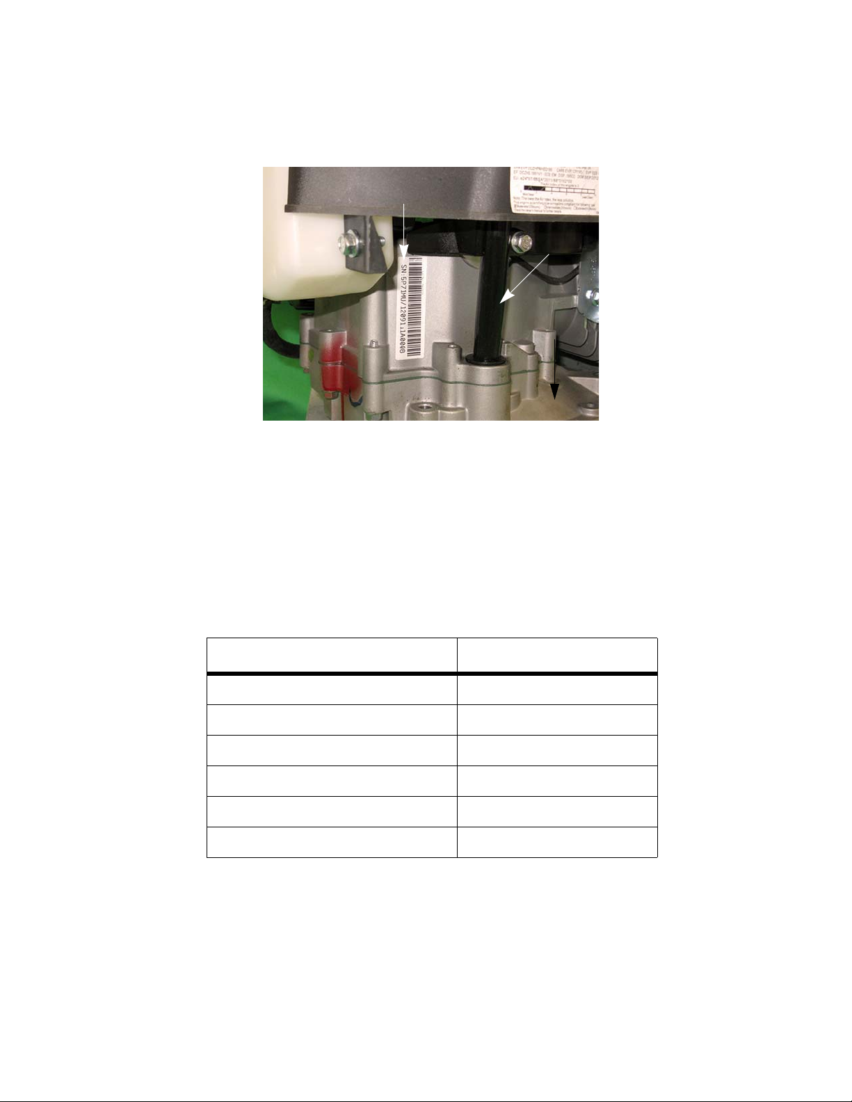
Figure 1.1
Model /serial number
Dipstick
Model and serial number
The model and serial number can be found on a white sticker with a bar code. The sticker is located behind the
dipstick. See Figure 1.1.
NOTE: The serial number will always start with the model number.
Maintenance
The recommended maintenance intervals listed in this manual are a guideline. They are ad justable for local con-
ditions.
Maintenance items Interval
Oil Change* 25 hrs
Clean/replace spark arrestor** 25 hrs
Replace the air filter 25 hrs
Spark plugs 50 hrs
Fuel filter 50 hrs
Clean the engine 25 hours
* First oil change at 5 hours
**If equipped
5
Page 12
P71 Series Vertical Shaft Engines
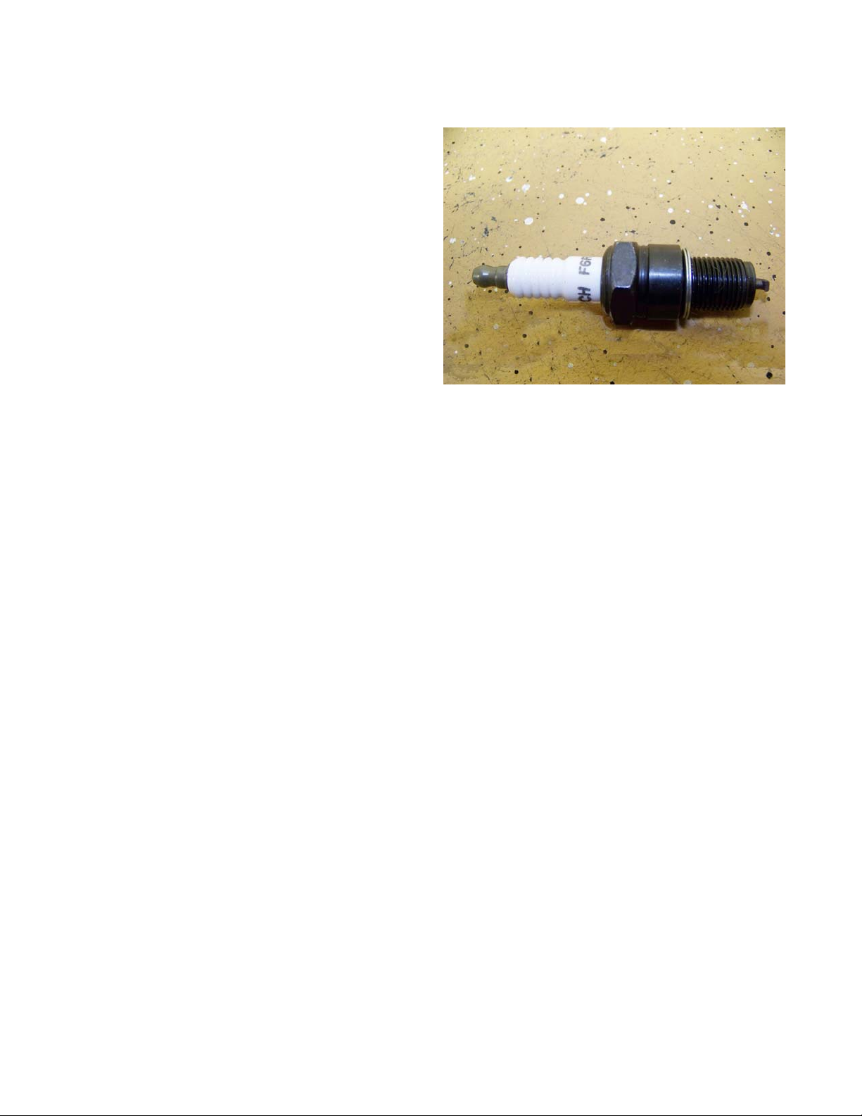
Figure 1.2
Spark plugs
The information in this manual applies to the MTD
engine. Some basic principles may apply to engines produced by other manufacturers.
As the saying goes “an ounce of prevention is worth a
pound of cure”. The same can be said about preventive
maintenance on outdoor power equipment. By changing
the spark plug and oil at recommended intervals many fai lures can be avoided.
NOTE: Please refer to Chapter 7: Ignition for the
complete service instructions on spark
plugs.
1. The spark plug used in the MTD engine is a F6RTC
(part # 951-10292) gapped to 0.024” - 0 .031” (0.60 -
0.80 mm). See Figure 1.2.
2. Wear rate will vary somewhat with severity of use. If
the edges of the center electrode are rounded-off,
or any other apparent wear / damage occurs, replace the spark plug before operating failure (no start) occurs.
3. Cleaning the spark plug:
NOTE: MTD does not recommend cleaning spark plugs. Use of a wire brush may leave metal deposits on the
insulator that causes the spark plug to short out and fail to spark. Use of abrasive blast for cleaning
may cause damage to ceramic insulator or leave blast media in the recesses of the spark plug. When
the media comes loose during engine operation, severe and non-unwarrantable engine damage may
result.
4. Inspection of the spark plug can provide indicati on s of th e op er a ting con d ition of th e en gine .
• Light tan colored deposits on insulator and electrode s is nor mal.
• Dry , black deposits on the insulator and electrodes indicate an over-rich fuel / air mixture (too much fuel or
not enough air)
• Wet, black deposits on the insulator and electrodes indicate the presence of oil in the combustion cham-
ber.
• Heat damaged (melted electrodes / cracked insulator / metal transfer deposits) may indicate detonation.
• A spark plug that is wet with fuel indicates that fuel is present in the combustion chamber, but it is not
being ignited.
6
Page 13
Air filter
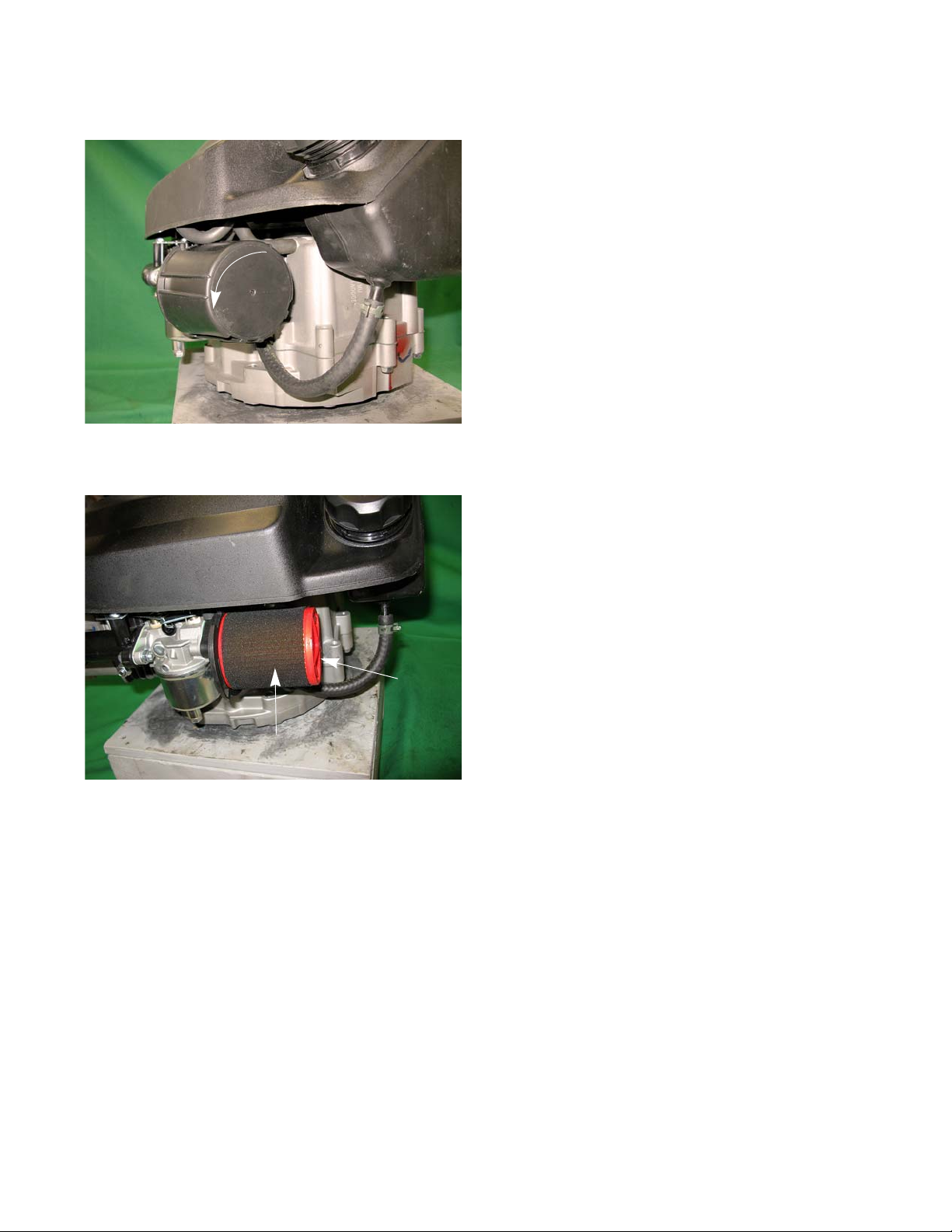
Figure 1.3
Figure 1.4
Air filter
Pre-cleaner
Introduction
To remove/replace the air filter:
1. Rotate the air filter housing counter clockwise,
approximately a quarter turn. See Figure 1.3.
2. Pull the housing off of the engine.
3. Remove the air filter and foam pre-cleaner. See
Figure 1.4.
4. Inspect the air filter and foam pre-cleaner.
NOTE: If a foam air pre-cleaner is dirty, but not in bad of
condition, it can be cleaned and reused. The paper
pleated filters can be shaken or lightly tapped to
free the debris from the filter.
NOTE: Never use compressed air on a paper air filter.
Compressed air will remove the tiny fibers that are
used to catch the dirt in the air. Without these
fibers the filter is useless.
5. Foam pre-cleaner can be washed in warm soapy
water.
NOTE: Before installing any foam filter, after it has been washed, it needs to be free of moisture.
NOTE: When drying a foam filter either squeeze it inside of a paper towel or let it air dry. DO NOT wring it
because the filter will tear.
NOTE: Always check with factory specification prior to servicing/replacing any engine components.
NOTE: Do not oil the foam pre-cleaner. The paper filer will absorb the oil and it will become plugged.
6. Install the pre-cleaner over the air filter.
7. Slide the air filter over the lip on the air filter base.
8. Install the air filter cover.
NOTE: When installing the air filter cover , the flat spot faces the engine block and the unhooked t ab should be
facing the bottom of the air filter base.
7
Page 14
P71 Series Vertical Shaft Engines
SAE 40
SAE 30
SAE 10W30/SAE 10W40
SAE 5W20
-4°F
14°F
32°F 50°F 68°F 86°F 104°F
-20°C
-10°C
0°C
10°C 20°C
30°C
40°C
Oil Chart
Oil type and capacity
The recommended oil for MTD engines is an SAE 30 oil with an SM API rating or better. The oil capacity is 17.0-
20.3 fl.oz (0.5-0.6 liters).
• Check the oil level daily and change the oil more frequently in severe operating conditions such as high
ambient temperature, dusty conditions, or high load use in exceptionally thick grass.
• Synthetic oil is a suitable alternative, but it does not extend service interva ls.
NOTE: MTD recommends the use of petroleum oil during the break in period to ensure the piston rings cor-
rectly break in.
• Synthetic vs. Petroleum based oil: To simply look at synthetic oil and to compare it with Petroleum based
oil there is very little difference. However, when you look at the two thro ugh a micro scope it is easy to see
the difference. Synthetic is made up of smaller molecules. This allows the oil to get int o area s th at pe troleum based oil cannot.
• No oil additives or viscosity modifiers are recommended. The performance of a good oil meeting the API
specifications will not be improved by oil additives.
NOTE: Some oil additives may cause severe and non-warrantable engine damage, constituting a lubrication
failure.
NOTE: If the oil is noticeably thin, or smells of gasoline, a carburetor repair may be needed before the engine
can be run safely.
8
Page 15

Introduction
Figure 1.5
Fully seat the
dip stick before
reading it
To check the oil:
1. Twist and remove the dipstick from the engine.
2. Clean the oil off of the tip of the dipstick.
3. Re-insert the dipstick and turn it until it is fully seated
to get the oil level reading. See Figure 1.5.
4. The oil level is determined by the highest point on the
dipstick that is completely covered with oil.
9
Page 16
P71 Series Vertical Shaft Engines
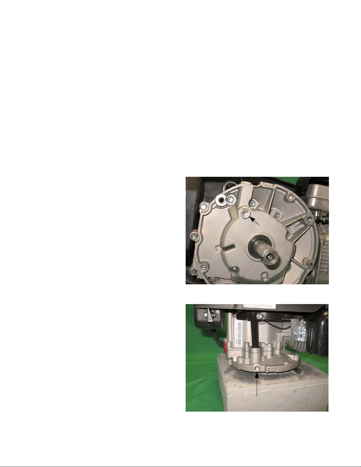
Figure 1.6
Drain plug
Figure 1.7
Drain plug
Changing the oil
NOTE: If the engine has been running, allow the engine to cool before doing any maintenance work.
NOTE: The oil should be changed after the first 5 hours of operation and every 50 hours there after.
There are three methods of changing the oil. The application the engine is mounted to will determine which
method to use:
NOTE: There are four ways to drain the oil out of the P 71 ser ies of eng ine s:
• Drain plug in the bottom of the sump.
• Drain plug at the base of the dip stick.
• Tip the engine and application over.
• Siphon the oil out through the dip stick tube.
NOTE: The method used would be determined by the application the engine is install on.
Drain Plug in the bottom of the sump
A. Access the bottom of the engine.
B. Place an approved oil drain pan under the engine
C. Remove the drain plug using a 1/4” extension.
D. Allow all of the oil to drain into the oil pan.
E. Apply a small amount of releasable thread sealing
compound such as Loctite® 565 to the threads of
the drain plug.
F. Install the drain plug, tightening it to a torque of 124
- 150 in lbs (14 - 17 Nm).
Drain Plug in the bottom of the sump
A. Place an approved oil drain pan next to the base of
the dip stick.
B. Remove the drain plug using a 1/4” extension.
C. Allow all of the oil to drain into the oil pan.
D. Apply a small amount of releasable thread sealing
compound such as Loctite® 565 to the threads of
the drain plug.
E. Install the drain plug, tightening it to a torque of 124
- 150 in lbs (14 - 17 Nm).
10
Page 17
Introduction
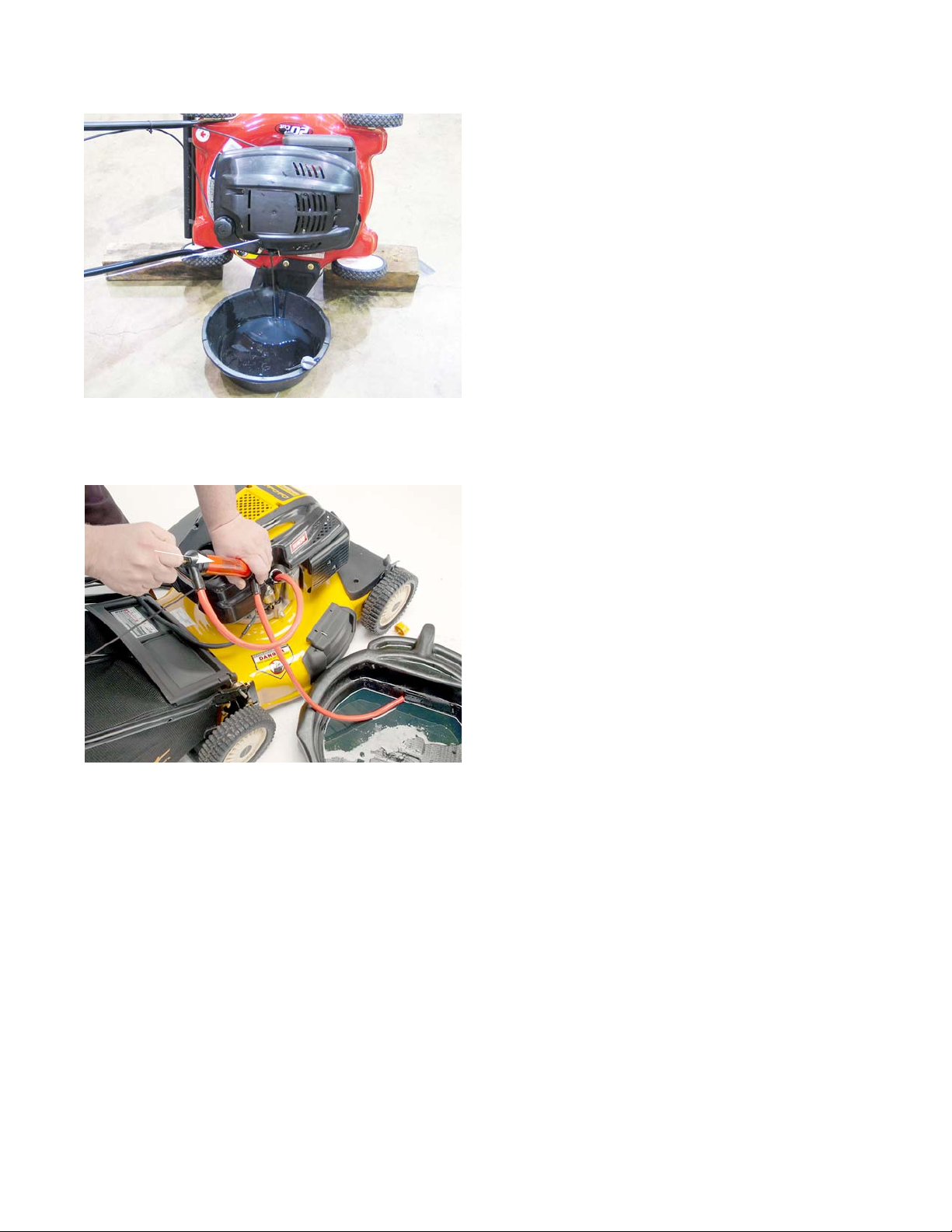
Figure 1.8
Figure 1.9
Siphon
Tip the engine and application over
A. Drain the fuel from the fuel tank into an approved
container
B. Remove the air filter.
NOTE: Any time the engine is tipped, the fuel inside the
carburetor will leak out into the air filter.
C. Place an approved oil drain pan on the ground.
D. Lean the application over on to the muffler side of the
engine.
E. Leave the application in this position until all of the oil
has drained out.
F. Tip the application back to its normal operating posi-
tion.
Siphon the oil out through the dip stick tube
A. Insert the siphon hose into the dip stick tube. See
Figure 1.9.
B. Siphon the oil out of the engine by following the pro-
cedures provided by the siphon manufacturer.
After draining the oil:
1. Fill engine with 20 oz (0.6 L) of SAE 10W-30 oil with a SM API rating or better.
2. Insert the dipstick and turn it until it is fully seated to get the oil level reading.
3. Check the dip stick to verify that the oil is at the proper level before returning to service.
11
Page 18
P71 Series Vertical Shaft Engines
! CAUTION! CAUTION
Gasoline and its vapors are extremely flammable. Use common sense when working around
the fuel system. Avoid sparks, open flames or heat sources that can ignite the fuel vapors.
Figure 1.10
Fuel filter
Fuel system
What you should know about fuel.
Most of the fuel presently available in North America is oxygenated to some extent. This is commonly done
through the addition of ethanol. Most engines offered for sale on outdoor power equipment in the North American
markets are designed to tolerate no more than 10% ethanol by volume
Ethanol is hygroscopic, meaning it absorbs water. If left exposed to air, it will draw water out of the air.
Ethanol is an oxygenator, which means that it will oxidize (corrode) metal that it comes into contac t with. Exposure to air causes fuel to go bad quickly, leaving gum and varnish deposits.
Fuel used in Cub Cadet outdoor power equipment should be no mo re than 30 days old. Becaus e it may a lready
have been stored at the refinery or gas station for a week or more, fuel should be purchased in small quantities and
stored in safety approved gas cans with the caps closed.
For storage, all fuel should be run out of the tank and engine. Anti-oxidation additives will help keep the fuel
fresher.
Servicing the fuel system
Inspect the fuel system every time the engine is operated. If dirty fu el is found in the fuel t ank or fuel tha t does not
smell “right”, drain the fuel tank and replace the fuel filter. Dispose of bad fuel in a safe and legal manner.
Refer to the units service manual for the procedures to drain the fuel tank.
Fuel filter
A dirty fuel filter can result in a lean run condition. The fuel filter should be replaced every 100 hours.
To replace the fuel filter:
NOTE: The fuel filter is located inside the fuel tank
nipple. See Figure 1.10.
1. Siphon the fuel out of the fuel tank and dispose of
the fuel in a safe and legal manner
2. Squeeze the tabs on the fuel line clamps and slide
them away from the filter.
3. Carefully slide the fuel line off of the fuel tank nipple.
If there are pieces of rubber on the barb of the fuel
tank nipple, replace the affected fuel line.
IMPORTANT: All MTD engines use low permeation
fuel line to meet EPA guidelines. When replacing the fuel lines, they must be replaced with
the same type of low permeation fuel line.
4. Pull the fuel filter out of the fuel tank nipple and dis-
card.
5. Install the new filter by following the above steps in reverse order.
6. Test run the engine and check for leaks before returning to service.
12
Page 19

Introduction
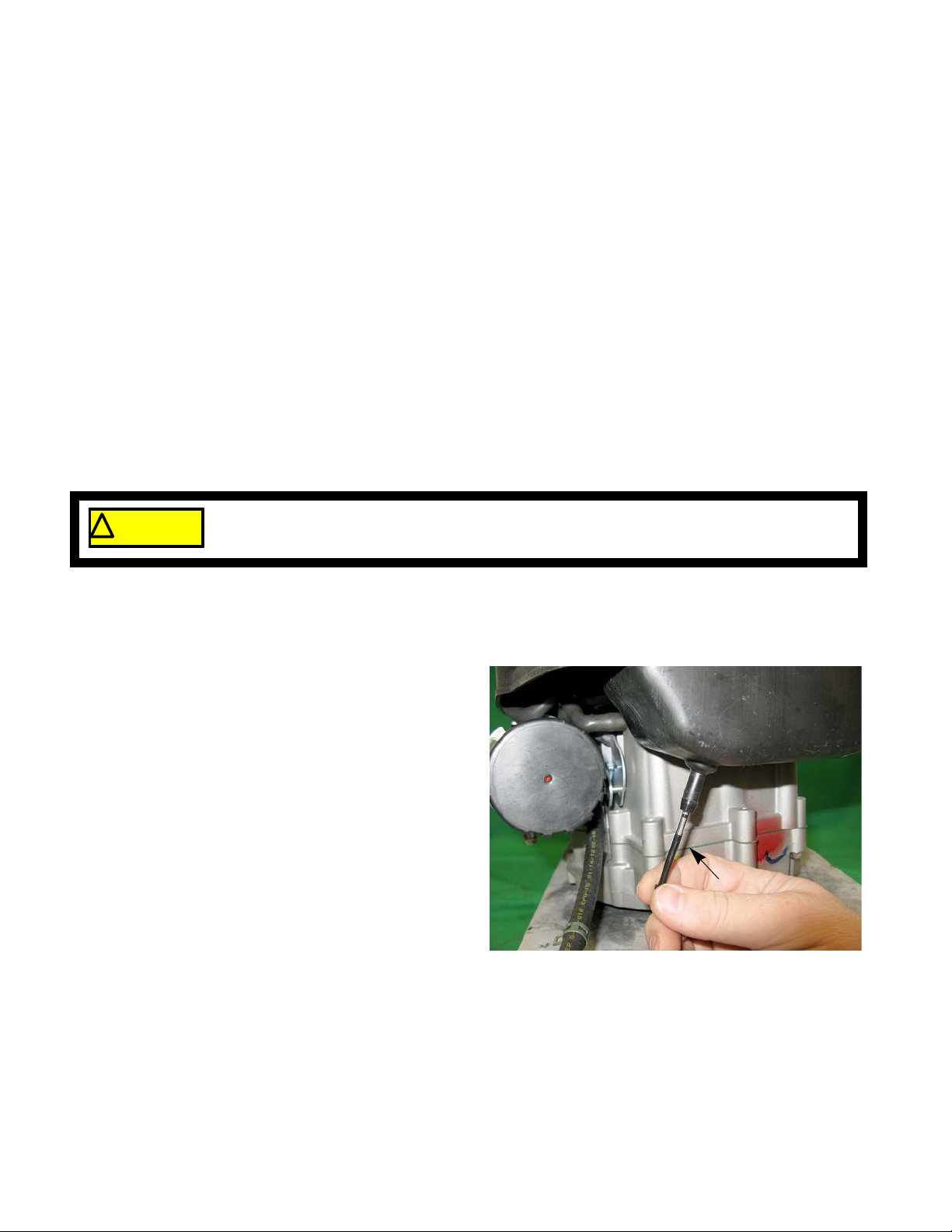
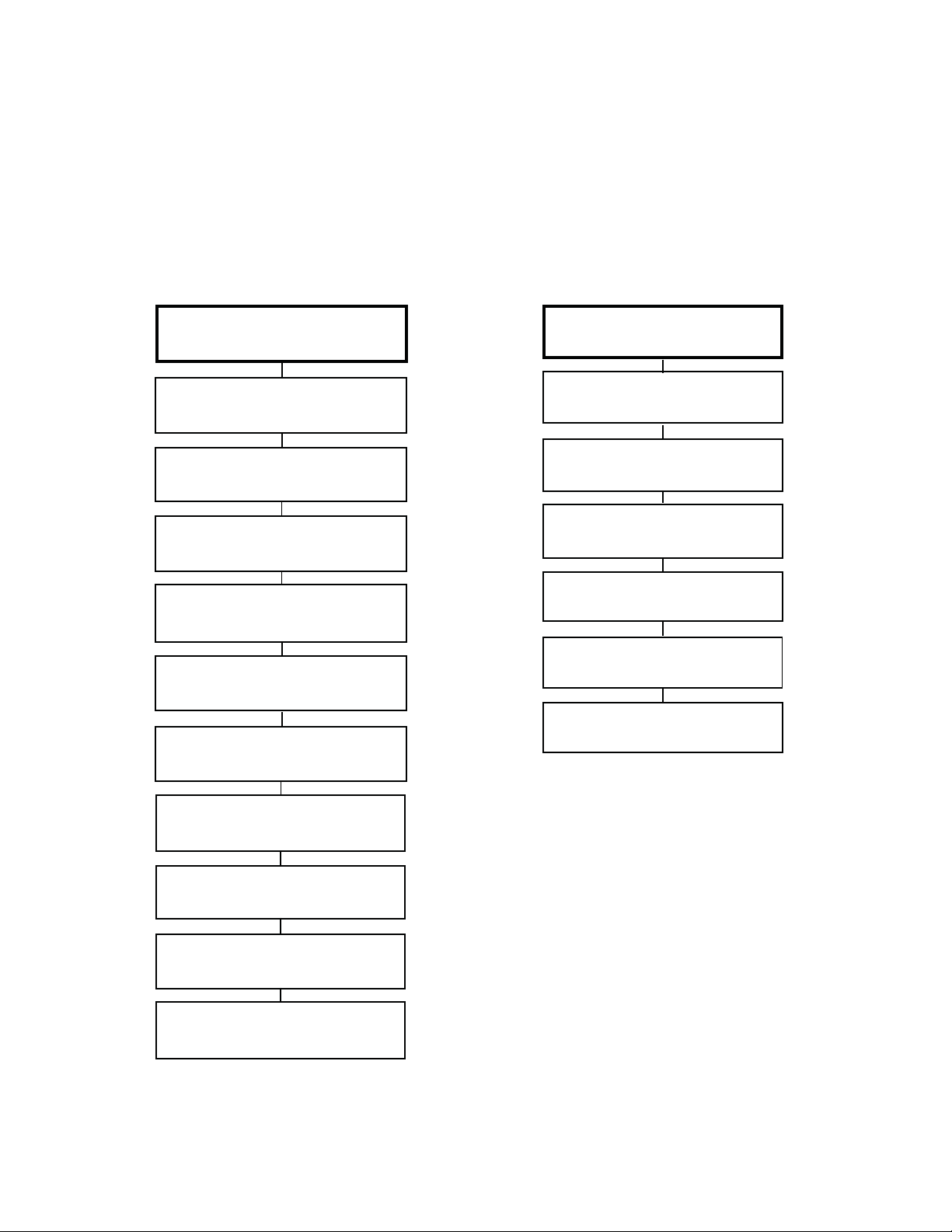
Figure 1.11
High tension lead
Muffler
Valve cover
Spark plug
Figure 1.12
Valves closed
(push rods slack)
Probe to confirm piston
is at top of travel
Old plastic dip stick
Valve lash
Valve lash is the clearance between the top of the valve stem and the rocker arm. The valve lash should be
checked after the first 25 hours of use and ever y 100 hour s a f ter th at. Valve lash can be checked and adjusted using
the following steps:.
1. If the engine has been run, allow it to cool thoroughly.
Position the mower for easy access to the cylinder
head.
2. Disconnect the high-tension lead from the spark plug
and ground it well away from the spark plug hole.
3. Remove the spark plug using a 13/16” spark plug
socket and ratchet. A flexible coupling or “wobbly”
extension may help. See Figure 1.11.
4. Remove the four bolts that secure the valve cover
using a 10mm wrench, and remove the valve cover
from the engine.
NOTE: If care is used not to damage the valve cover gas-
ket, it can be re-used.
5. Confirm that the piston is at T
compression stroke.
NOTE: An old plastic dip stick makes a nice probe that will
not damage the piston crown. See Figure 1.12.
• The compression stroke can be distinguished
from the overlap stroke by the presence of air
pressure at the spark plug hole and the fact that
neither of the valves should move significantly on
the compression stroke.
• There is an automatic compression release mech-
anism that “bumps” the exhaust valve as the piston
rises on the compression stroke. At TDC, the
exhaust valve should be fully closed.
op-Dead-Center on the
13
Page 20
P71 Series Vertical Shaft Engines
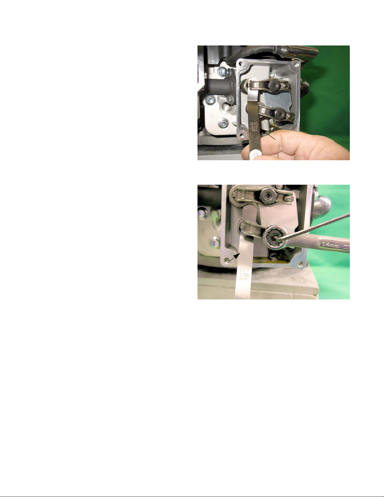
Figure 1.13
0.005” feeler
gauge
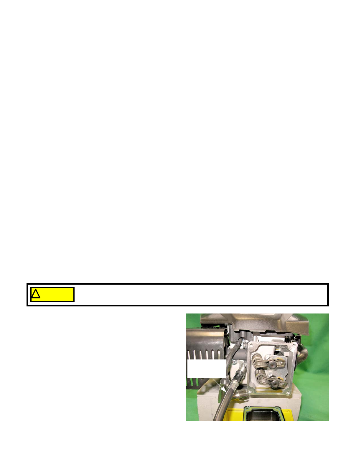
Figure 1.14
0.007” feeler
gauge
6. Check valve lash between each valve stem and
rocker arm using a feeler gauge.
7. Intake valve lash (top valve) should be 0.004” -
0.006” (0.10 - 0.15 mm). See Figure 1.13.
8. Exhaust valve lash (bottom valve) should be 0.006”
- 0.008” (0.15 - 0.20 mm). See Figure 1.14.
9. Use a 3 mm hex key to loosen the jam set screw ,
and a 14mm wrench to adjust the rocker arm fulcrum nut. See Figure 1.14.
• Tighten the rocker arm fulcrum nut to close-up
the clearance between the end of the valve
stem and the contact point on the rocker arm.
• Loosen the rocker arm fulcrum nut to open-up
the clearance between the end of the valve
stem and the contact point on the rocker arm.
10. Hold the fulcrum nut with a 14mm wrench, tighten
the jam set screw to a torque of 80 - 106 in lbs (9 12 Nm) using a 10 mm wrench.
11. Double-check the clearance after tightening the jam nut, to confirm that it did not shift. Re-adjust if necessary.
12. Rotate the engine through several compression cycles:
• Observe the movement of the valve gear.
• Return the piston to TDC compression stroke and re-check the valve lash to confirm consistent movement
of the valve gear, including the slight bump to the exhaust valve from the automatic compression release.
13. Clean-up any oil around the valve cover opening, clean the valve cover, replace the valve cover gasket if necessary.
14. Install the valve cover, tightening the valve cover screws to a torque of 62 - 80 in lbs (7 - 9 Nm).
15. Install the spark plug.
16. Test run the engine befo r e returning it to service.
14
IMPORTANT: Over tightening the valve cover will cause it to leak.
Page 21

Introduction
Exhaust system
The exhaust system is a frequently overlooked component of an engine. It is important to make sure the muffler
is in good condition and free of blockage.
NOTE: A blocked muffler will result in poor performance. If a muff ler is completely blocked, the engine may not
start.
Cleaning the engine
1. To maintain a proper operating temperature and to keep the equipment looking good, all debris should be
removed from the engine.
2. It is recommended to use compressed air to blow all of the debris off of the engine.
NOTE: A pressure washer may be used to clean outdoor power equipment but only after the unit has been
allowed to properly cool.
General torque specifications
Size M4 M5 M6 M8 Size M10 M12 M14
Grade 4.8in lbs11223893ft lbs162743
Nm 1.2 2.5 4.3 10.5 Nm 21.7 36.6 58
5.8in lbs152850120ft lbs203555
Nm 1.7 3.2 5.7 13.6 Nm 27.1 47.5 76
8.8in lbs265188216ft lbs356197
Nm 2.9 5.8 9.9 24.4 Nm 47.5 82.7 132
10.9 in lbs 36 72 124 300 ft lbs 49 86 136
Nm 4.1 8.1 14 33.9 Nm 66.4 116.6 184
12.9 in lbs 44 86 146 360 ft lbs 60 103 162
Nm 5 9.7 16.5 40.7 Nm 81.4 139.7 220
Noncritical
in lbs183560150ft lbs254570
fasteners in
aluminum
Nm 2 4 6.8 17 Nm 33.9 61 95
15
Page 22

P71 Series Vertical Shaft Engines
Useful Engine Specifications
Description SAE Metric
Engine displacement 11.9 cubic inch 195cc
Spark plug gap 0.024” - 0.031” 0.6 - 0.8 mm
Spark plug torque 177 - 221 in lbs 20 - 25 Nm
Ignition module air gap 0.004” - 0.020” 0.10 - 0.50 mm
Intake valve lash 0.004” - 0.006” 0.10 - 0.15 mm
Exhaust valve lash 0.006” - 0.008” 0.15 - 0.20 mm
Oil capacity 20 oz 0.6 L
16
Page 23

Definitions
! CA UTION! CA UTION
The first two rules in troubleshooting is to cause no further harm to the engine and prevent
injuries. Always make sure to check the oil for level and condition before starting an engin e.
Also check attachments for damage and make sure they are firmly mounted.
BASIC TROUBLESHOOTING
CHAPTER 2: BASIC TROUBLESHOOTING
Troubleshooting
Diagnosis
shooting.
Introduction
Diagnosing an engine is an art form that is built upon several factors. First and most importantly is a good understanding of how the engine works. The second is skills that have been honed by experience. Finally the use of visual
observations and a structured, systematic approach to troubleshooting a problem.
The first part of this chapter will outline the steps of troubleshooting an engine so a technician can form a proper
diagnosis. The second half of this chapter will describe specific procedures and tests to perform while troubleshooting.
Steps to troubleshooting
NOTE: The steps and the order of the steps that follow are a suggested approach to troubleshooting the MTD
Define the problem
The first step in troubleshooting is to define the problem:
- The act of gathering information by preforming tests and direct observations.
- Developing and testing theories of what the problem is, based on the information gathered in trouble-
engine. The technician does not necessarily have to follow them as described in this chapter.
• Crankshaft will not turn.
A. Starter not working
B. Engine in a bind (external - attachment jammed)
C. Engine in a bind (internal - engine seized)
• Crankshaft turns, no start
• Starts, runs poorly
A. St arts, then dies
B. Runs with low power output
C. Make s unusual smoke when running
I. Black smoke, usually heavy
II. White smoke, usually heavy
III. Blue smoke, usually light
D. Makes unusual sounds when running
I. Knock
II. Click
III. Chirp
17
Page 24

P71 Series Vertical Shaft Engines
IV. Unusual exhaust tone
There are tools that the technician can use in order to define the problem, such as:
1. Interview the customer.
1a. Get a good description of their complaint.
1b. If it is an intermittent problem, verify what conditions aggravate the problem as best as possible.
1c. Get an accurate service history of the equipment.
1d. Find out how the customer uses and stores the equipment.
2. Direct observation:
2a. Do not automatically accept that the customer is correct with their description of the problem. Try to
duplicate the problem.
2b. Check the general condition of the equipment (visually).
I. Cleanliness of the equipment will indicate the level of care the equipment has received.
II. Make sure the engine and attachments are securely fastened.
III. The tune-up factors.
NOTE: Most hard starting and poor running conditions can be solved by performing a tune-up.
a. Check the condition and amount of oil in the crankcase.
b. Check the level and condition of the fuel.
c. Check the ignition and “read” the spark plug.
d. Look for obvious signs of physical damage, exhaust system blockage or cooling system block-
age.
18
Page 25

Identify factors that could cause the problem
This is the second step in the troubleshooting process.
1. Crankshaft will not turn.
BASIC TROUBLESHOOTING
A. Starter not working
I. A dead battery.
II. A bad ground
III. A failure in the electrical circuit.
IV. A failure of the starter itself.
B. Engine in a bind (external - atta ch men t jamme d)
the engine either failed or has something jammed in it, locking up the system.
C. Engine in a bind (internal - engine seized)
likely suspects are:
I. Complete hydraulic lock (easy fix).
II. Bent crankshaft (unrepairable)
III. Interna l binding, crankshaft, connecting rod or piston (unrepairable)
2. Crankshaft turns, no start.
2a. Most gasoline engine diagnosis involves isolating problems in the four critical factors an engine needs to
run properly:
I. Ignition
II. Compression
needs sufficient sealing to generate the vacuum needed to draw in and atomize the next intake
charge.
- sufficient spark to start combustion in the cylinder, occurring at the right time.
. This can be an electrical failure or a mechanical failure. The likely suspects are:
. This usually indicates that the unit being powered by
. This is usually either a quick fix or a catastrophic failure. The
- enough pressure in the cylinder to convert combustion into kinetic motion. It also
III. Fuel
IV. Flow
2a. Isolate the ignition system and compression from the fuel system by preforming a prime test.
I. Burns prime and dies. This would indicate a fuel system issue.
II. Does not burn prime. Not a fuel system issue. Check for an ignition, compression or flow problem.
2c. Compression or ignition problem
I. Check the engine stop and safety switch.
II. Test the ignition system using a proper tester.
III. Replace the spark plug with a new one or a known good one.
IV. Check compression or leak down.
V. Check valve lash.
VI. Check valve timing/actuation.
VII. Check exhaust.
3. Starts, runs poorly
3a. Starts, then dies
- correct type and grade of fresh gasoline; in sufficient q uantity, atomized (tiny droplets) and in
correct fuel/air proportions.
- if all of the above conditions are met but the flow of air is constricted on the inlet or exhaust
side, it will cause the engine to run poorly or not at all. This also includes ensuring the valves are
timed to open at the proper time.
19
Page 26

P71 Series Vertical Shaft Engines
I. Run the engine with a spark tester in-line between the sp ark plug wire and the sp ark plug or use an
oscilloscope and see if the spark goes away at the same time the engine dies.
II. Check choke operation.
a. Black smoke?
b. Wet plug?
III. Prime test immediately after engine dies. If it restarts, this may indicate a problem with fuel flow to
the carburetor. Check the gas cap, fuel line, fuel filter, and the float in the carburetor.
3b. Runs with low power output.
I. Look for unusual exhaust color (smoke).
II. Unusually hot muffler (may glow red).
a. Retarded ignition
b. Exhaust valve opening early (lash too tight)
III. Mechanical bind
a. A slightly bent crankshaf t. In some cases the drag may increase and decrease as the crankshaf t
rotates. This produces a pulsing feeling that is different than a jerk back.
b. Parasitic external load. A bind in the equipment the engine is powering.
c. Internal drag from a scored piston or similar damage.
IV. Low governor setting or stuck governor.
a. Check RPMs using a tachometer.
b. RPMs should not droop under moderate to heavy loads.
V. Low compression
a. Check valve lash
b. Check compression
c. Check leak down to identify the source of the compression loss.
VI. Flow blockage
a. Exhaust blockage, usually accompanied by an unusual exhaust sound.
• Just as a throttle on the carburetor controls the engine RPMs by limiting the amount of air an
engine can breathe in, an exhaust blockage will limit engine performance by constricting the
other end of the system.
• The muffler itself my be blocked.
• The exhaust valve may not be opening fully, possibly because of extremely loose valve lash
settings.
• The exhaust valve seat may have come loose in the cylinder head. This may cause a loss of
compression, a flow blockage or it may randomly alternate between the two.
NOTE: The cause of an exhaust valve coming loose is usually over heating.
b. Intake blockage
• An intake blockage up-stream of the carburetor will cause a rich fuel/air mixture and constrict
the amount of air that the engine can dr aw in, limitin g pe rf or ma n ce .
• The intake valve not fully opening. A possible cause of this is loose valve lash.
20
Page 27

V. Makes unusual smoke when running
BASIC TROUBLESHOOTING
a. Black smoke
• Not enough air: air flow blockage or a partially closed choke.
• Too much fuel: carburetor float or float valve stuck or metering / emulsion issues with the carburetor.
b. White smoke
• Oil in muffler, usually the result of improper tipping. The engine will “fog” for a minute or so,
then clear-up on its own.
• Massive oil dilution with gasoline. It may be caused by improper tipping. It can also be caused
by leaky carburetor float valve, if there is a down-hill path from the carburetor to the intake port.
Check oil for gasoline smell, repair carburetor.
c. Blue smoke
PCV system
• May be blocked or unplugged.
• May be over-come by massive over-filling or oil dilution with gasoline.
• Will cause oil to exit the engine via any low-resistance paths.
Piston rings
• Confirm with leak-down test.
• Smoke will be more pronounced under load.
, usually heavy, usually indicates a rich air fuel mixture
, usually heavy
, usually light.
• Repair may not make economic sense.
Valve gu ide s (a nd intake valve stem sea l).
• Smoke will be more pronounced on over-run.
VI. Makes unusual noise when running
a. Knock
• Check for loose mounting of engine or driven implement
• Rotate crankshaft back-and-forth to check for loose connecting rod.
b. Click
• Clicks and pops on engine shut-down: Compression release coming into play as the engine
RPMs cross the activation threshold. This will have no ill effects on engine performance.
• Half-engine speed clatter: loose valve lash.
• Half-engine speed clatter, slightly heavier: wrist-pin.
• Rhythmic heavy-light engine speed click: piston slap
c. Spark-knock
• Advanced ignition timing
• Low octane fuel
• Over-heating engine (check for blocked cooling air flow)
• Carbon build-up in cylinder: glowing carbon chunks pre-igniting air fuel mix.
d. Chirp
• Compression, blowing-by the fire-ring of a damaged head gasket will sometimes produce a
21
Page 28

P71 Series Vertical Shaft Engines
chirping noise.
• Confirm with a compression test and leak-down test.
e. Unusual exhaust tone
Splashy or blatty
• Splashy idle usually indicates a slight rich condition.
• May indicate an exhaust blockage, usually slightly muffled.
Backfire
• On over-run: unburned fuel igniting pa st ex haust valve . Mixture no t bur ning com pletely in combustion chamber. It may be too rich or it may be spark-plug or ignition problem.
• Occasional, under load: engine momentarily runs lean, usually will cycle with float bowl level or
governor pull-in, sometimes sounds like a slight stumble. Ethanol content exceeding 10% will
make the engine run artificially lean.
Skip
• Usually ignition related.
• Run the engine with a spark tester in-line between the spark plug wire and the spark plug or
use an oscilloscope and see if the spark goes away at the same time the engine dies.
4. Engine over-speed
A. Continual over-speed
• Binding or damaged external governor linkage or carburetor throttle.
• Mis-adjusted governor arm.
• Internal governor failure.
B. Momentary over-speed
• Intermittent bind (very unusual).
• Interference: This is fairly common when debris can fall on the governo r linkage d uring n ormal
operations.
5. Engine RPMs surge (hunting)
A. Over-governed condition- Return spring replaced with wrong part or hooked into wrong hole.
NOTE: This is an extremely rare condition, usually created by tampering.
B. Lean Air-fuel mixture condition- When AFR (Air Fuel Ratio) is significantly below stoichiometric ratio
(14.7:1) engine RPMs sink until they reach a po int tha t can be su pp or te d by the availa b l e fuel . Th is
causes a momentary surge in power until the available fuel is consumed, then the RPMs fall again,
repeating the cycle.
• Too much air: look for an air leak in the intake tract
• Not enough fuel: look for fuel supply or carburetor problems
22
Page 29

BASIC TROUBLESHOOTING
Repairing the problem
The third step in the troubleshooting process is to repair the problem. This step consists of:
A. Form a diagnosis by using all of the information gathere d from the tro ub leshooting th at was p erforme d.
B. Physically perform the repair.
The fourth, and hopefully final, step in the troubleshooting process is the follow through. This step consists of:
A. Thoroughly test the repaired equipment: confirming that the initial diagnosis was correct. If it was
wrong, start the troubleshooting process over again.
NOTE: Sometimes the engine will have multiple problems at the same time. By performing one repair, other
issues may show up that are unrelated to the first repair.
B. Delivery to customer: We are not just repairing equipment, we are repairing customers.
• Inoculate against recurring problem with education, e.g.: if the problem was caused by stale
fuel, make sure the customer is aware that fuel go es bad ove r tim e.
• Make sure the customer understands the repair, preventing “superstitious” come-backs.
23
Page 30
P71 Series Vertical Shaft Engines
! CA UTION! CAUTION
If the engine is not centered at top dead center, the engine will rotate when compressed air is
introduce to the combustion chamber.
Figure 2.1
Tester Adapter
Leak-down
Prime test
To perform a prime test:
1. Prime the engine through the carburetor throat using a squirt bottle, filled with clean fresh gasoline.
2. Make sure the throttle is in the run position.
3. Attempt to start the engine.
4. If the engine starts and runs long enough to burn the prime, the problem is effectively isolated to the fuel system. Proceed to Chapter 4: The Fuel System and Governor.
5. If the engine did not start, check ignition system as described in Chapter 7: Ignition System.
6. If the ignition system is working, check the compression or perform a leak down test.
Leak-down test
A leak-down test is the preferred method to test the engine’s ability to compress the charge. It will also show
where pressure is leaking from.
To perform a leak-down test:
NOTE: A leak down test pressurizes the combustion chamber with an external air source and will allow the
technician to listen for air “leaking“ at the valves, piston rings and the head gasket.
NOTE: These are general instructions. Read and follow the instructions that came with the tester before
attempting to perform this test.
• If possible, run the engine for 3-5 minutes to warm up the engine.
• Remove the spark plug and air filter.
• Find top dead center of the compression stroke.
1. Remove the spark plug.
2. Remove the valve cover.
3. Rotate the engine to top dead center (compression
stroke)
NOTE: An old plastic dip stick makes a nice probe
that will not damage the piston crown.
4. Lock the engine to prevent it from rotating when
5. Thread the lead down tester adapter hose into the
24
pressurized.
engine. See Figure 2.1.
Page 31

6. Attach the leak down tester to an air supply of 90
Figure 2.2
Leak down tester
psi.
7. Adjust the tester until the gauge’s needle is pointin g
to the set position.
8. Connect the tester to the adapter.
NOTE: If the engine rotates it was not at top dead
center.
9. Check the reading on the gauge.
NOTE: If the reading is >15% pressure loss, investi-
gate for the cause of the leak by:
• Listen for air escaping through the ca rb ur et or
(intake valve leak)
• Listen for air escaping through the muffler
(exhaust valve leak)
• Listen for air escaping through the dipstick tube (blow by, head gasket leak)
NOTE: it is normal for a little leakage to be heard from the dipstick tube.
BASIC TROUBLESHOOTING
10. Disconnect the tester.
11. Rotate the engine to BDC.
12. Loosen the rockers to prevent them from opening the valves.
13. Re-attach the tester.
14. Compare the results.
NOTE: If the cylinder passes at TDC but fails at BDC, the bottom of the cylinder is scored. If it passes at BDC,
but not at TDC, the top of the cylinder is scored.
25
Page 32

P71 Series Vertical Shaft Engines
Figure 2.3
Compression gauge
Compression test
To perform a compression test:
NOTE: Compression should be in the range of 55 - 80 PSI (3.8 - 5.5 Bar).
• Disconnect the high-tension lead from the spark plug and ground it well away from the spark plug hole.
• Remove the spark plug using a 13/16” or 21mm wrench. A flexible coupling or “wobbly” extension may
help.
• Pull the starter rope several times to purge any fuel or oil from the combustion chamber.
NOTE: Air compresses readily, liquid does not. Liquid in the combustion chamber will result in an artificially
high compression reading.
1. Install a compression gauge in the spark plug hole.
2. Confirm that the gauge is “zeroed”, then pull the
starter rope repeatedly, until the needle on the
gauge stops rising. See Figure 2.3.
3. Interpreting compression readings.
Readings in
psi
<20
(1.4 Bar)
20 - 55
(1.4-3.8 Bar)
55 - 80
(3.8-5.5 Bar)
>80
(>5.5 Bar)
Compression Readings
Possible causes
Most likely a stuck valve or
too tight of a valve lash,
provided the starter rope
pulls with normal effort.
Valve seat damage or piston ring and/or cylinder
wear.
Normal readings
Excessive valve lash, a
partial hydraulic lock, a bad
cam or a bad automatic
compression relief.
26
Page 33

PCV testing
Figure 2.4
Breather hose
Figure 2.5
BASIC TROUBLESHOOTING
The PCV (Positive Crankcase Ventilation) valve is
located in the engine block and allows the crankcase pressure to escape.
Leakage and blockage are the two failure modes for a
PCV system. Either mode will cause crankcase pressure
to build-up, though the effects of a blocked PCV are gene rally more dramatic. Increased case pressure will result in
oil entering the combustion chamber.
NOTE: The PCV chamber is vented to the carburetor
throat through a molded rubber hose. See Figure
2.4.
To measure the crankcase pressure:
1. Remove the dipstick.
2. Attach a manometer to the dipstick tube.
3. Start the engine.
4. Read the measurement on the manometer. See
Figure 2.5.
NOTE: A typical reading, under no load, is around -10”
(-25.4cm) of water.
NOTE: Experimentation by MTD’s Training and Education
Department has revealed the following characteristics of MTD engines:
• A leaky PCV system will not build-up substantial
case pressure.
• A leaky PCV system will allow the engine to ingest
contaminants through the system, accelerating
engine wear.
• A blocked PCV system will allow crankcase pres-
sure to build very rapidly. Noticeable oil fumes will
be evident in the exhaust within several minutes of
normal operation.
27
Page 34

P71 Series Vertical Shaft Engines
Ignition Troubleshooting
Engine will
not start
Engine runs
erratically or shuts
off, restarts
Check for spark
Spark No Spark
Check for the correct spark
plug
Check flywheel and key for
damage or sheared key
Set proper air gap on
ignition module
Test ignition module
for intermittent or
weak spark
Check electric starter and
battery if applicable
Replace spark plug
Isolate engine from
equipment and repeat
test
Spark No Spark
Equipment problem,
check switches, wiring
and equipment controls
Engine problem, check
for shorts or grounds in
wiring
Disconnect ignition
ground-out wire at
the ignition module &
repeat test
Check for proper air gap
on ignition module
and repeat test
Check flywheel magnets
for strength
Test ignition module
Troubleshooting flow charts
28
Page 35

Engine Operation Problems
Excessive engine loading
OVERHEATS
Low oil level or wrong viscosity oil
Cooling air flow obstructed or
clogged cooling fins
Carburetor improperly adjusted or
improper RPM setting*
Ignition timing or
incorrect spark plug
Carbon in the combustion
chamber
ENGINE KNOCKS
Check for excessive carbon in
combustion chamber
Loose flywheel examine key, key way
and proper flywheel nut torque
Ignition timing or
incorrect spark plug
Loose or worn connecting rod
Worn cylinder
Associated equipment loose or
improperly adjusted
BASIC TROUBLESHOOTING
29
Page 36
P71 Series Vertical Shaft Engines
SURGES OR RUNS UNEVENLY
Fuel cap vent obstructed
Dirty carburetor or air filter
Carburetor improperly adjusted
Governor sticking, binding or
improper RPM setting
Carburetor linkage, shafts or
shutters sticking or binding
Intermittent spark, check ignition
or incorrect spark plug
Oil level above full
Wrong viscosity oil
Engine cooling fins dirty causing
overheating
Breather damaged, dirty or
improperly installed
Excessive engine speed
Damaged gaskets, seals or "O" rings
EXCESSIVE OIL CONSUMPTION
Valve guides worn excessively
Worn or glazed cylinder
Piston rings worn
Lean carb setting causing
overheating (adjustable carb)
Engine Operation Problems
30
Page 37
ENGINE MISFIRES
Improper Valve Lash
Weak valve spring
Excessive carbon build up
Carburetor improperly adjusted
Ignition timing or
incorrect spark plug
Valves sticking or not
seating properly
Wrong or fouled spark plug
Bent crankshaft
ENGINE VIBRATES
EXCESSIVELY
Attached equipment out
of balance
Loose mounting bolts
If applicable counter balance not
properly aligned
Engine Operation Problems
BASIC TROUBLESHOOTING
31
Page 38
P71 Series Vertical Shaft Engines
BREATHER PASSING OIL
Oil level too high
Breather damaged, dirty or
improperly installed
Damaged gaskets, seals
or "O" rings
Excessive RPM or improper
governor setting
Angle of operation too severe
Piston rings not properly seated
or ring end gaps are aligned
LACKS POWER
Air intake obstructed
Lack or lubrication or improper
lubrication
Carburetor improperly adjusted
Exhaust Obstructed
Improper valve lash
Loss of compression (worn rings,
blown head gasket)
Engine Operation Problems
32
Page 39

Figure 3.1
Figure 3.2
Air filter
CHAPTER 3: AIR INTAKE SYSTEM
Air filter
To remove/replace the air filter:
1. Rotate the air filter housing counter clockwise,
approximately a quarter turn. See Figure 3.1.
2. Pull the housing off of the engine.
AIR INTAKE SYSTEM
3. Remove the air filter and foam pre-cleaner. See
Figure 3.2.
4. Inspect the air filter and foam pre-cleaner.
NOTE: If a foam air pre-cleaner is dirty, but not in
bad condition, it can be cleaned and reused.
The paper pleated filters can be shaken or
lightly tapped to free the debris from the filter.
NOTE: Never use compressed air on a paper air fil-
ter. Compressed air will remove the tiny
fibers that are used to catch the dirt in the
air. Without these fibers the filter is useless.
5. Foam pre-cleaner can be washed in warm soapy
water.
NOTE: Before installing any foam filter, after it has been washed, it needs to be free of moisture.
NOTE: When drying a foam filter either squeeze it inside of a paper towel or let it air dry. DO NOT wring it
because the filter will tear.
NOTE: Always check with factory specification prior to servicing/replacing any engine components.
NOTE: Do not oil the foam pre-cleaner. The paper filer will absorb the oil and it will become plugged.
6. Install the pre-cleaner over the air filter.
7. Slide the air filter over the lip on the air filter base.
8. Install the air filter cover.
NOTE: When installing the air filter cover , the flat spot faces the engine block and the unhooked t ab should be
facing the bottom of the air filter base.
33
Page 40

P71 Series Vertical Shaft Engines
Figure 3.3
Air filter base
Figure 3.4
Breather hose
Figure 3.5
Hose pinching pliers
Carburetor removal/replacement
To remove/replace the carburetor:
1. Remove the shroud by following the procedures
described in Chapter 6: Starters.
NOTE: Replace the fuel cap to minimized fuel spill-
age.
2. Remove the air filter by following the procedures
described in the previous section of this chapter.
3. Remove the two screws that hold the air filter base
to the carburetor using a T-25 torx driver. See
Figure 3.3.
4. Remove and discard the air filter base gasket.
5. Disconnect the breather hose from the carburetor.
See Figure 3.4.
6. Clamp off the fuel line to prevent fuel from leaking
when the line is disconnected.
IMPORTANT: Take care that the fuel lines are not
damaged when clamping them off. Never
insert a screw or anything else into the fuel
line to prevent fuel from coming out. This will
damage the inside of the fuel line.
34
NOTE: There are commercially availa b le ho se
pinching pliers that will not damage the fuel
lines. See Figure 3.5.
Page 41

AIR INTAKE SYSTEM
Figure 3.6
Throttle linkage
Mounting nuts
Paint mark
Calibration code
Figure 3.7
Governor spring bracket
Rib
7. Mark the hole that the throttle linkage is inserted into
with a paint pen or marker. See Figure 3.6.
8. Remove the two mounting nuts and bolts that hold
the carburetor to the intake manifold. See Figure 3.6.
9. Disconnect the choke rod.
10. Disconnect the throttle linkage.
11. Disconnect the fuel line.
12. Drain the fuel into an approved container.
13. Remove the fuel line from the fuel t ank and discard it.
NOTE: MTD uses low permeation fuel lines to meet EPA
guidelines. Low permeation fuel lines are made
with a soft membrane that lines the inside of the
line. Any tear in this membrane will allow the fuel
to get in between the membrane and the hose,
choking off the fuel flow.
NOTE: Every time the fuel line is pulled off of a brass nip-
ple, the fuel line must be replaced with the same
type of low permeation fuel line.
14. Install the carburetor by following the previous steps
in reverse order.
NOTE: The carburetors are not inter -changeable from one
engine model to another. To help prevent carburetor mix-ups, the calibration number is stamped on
the carburetor by the fuel nipple. The calibration
code will be similar to or the same as the engine
model number.
NOTE: The slot in the governor spring bracket must fit
over the rib on the inboard carburetor mounting
flange. See Figure 3.7.
NOTE: Tighten the carburetor mounting nuts to a torque of
80 - 106 in lbs (9 - 12 Nm).
15. Test run the engine before returning to service.
35
Page 42

P71 Series Vertical Shaft Engines
To avoid personal injury or property damage, use extreme care in handling gasoline. Gasoline is extremely flammable and the vapors are explosive. Serious personal injury can occur
when gasoline is spilled on yourself and/or your clothes which can ignite. Wash your skin
and change clothes immediately
! WAR N IN G! WAR N IN G
Figure 3.8
Nut
Screws
Figure 3.9
Vane
Bracket
Intake manifold
To remove/replace the intake manifold:
1. Remove the carburetor by following the procedures
described in the previous section.
2. Remove the two screws that hold the intake manifold to the cylinder head using a 10 mm wrench.
See Figure 3.8.
3. Remove the nut that holds the intake manifold to the
support stud using a 10 mm wrench.
4. Slide the manifold off of the stud.
5. Remove and discard the gaskets.
NOTE: If the manifold is to be replaced, remove the
autochoke vane and bracket:
• Slide the vane off of the post on the bracket.
• Remove the two screws that hold the bracket to
the manifold using a 8 mm wrench. See Figure
3.9.
6. Install the manifold with new gaskets by following
the previous steps in reverse order.
NOTE: Tighten the two screws that hold the mani-
fold to the cylinder head to a torque of 62 80 in lbs (7 - 9 Nm).
NOTE: Tighten the nut on the support stud to a
torque of 80 - 106 in lbs (9 - 12 Nm).
7. Test run the engine before returning to service.
36
Page 43

FUEL SYSTEM AND GOVERNOR
Figure 4.1
NBR inner liner
THV barrier layer
NBR intermediate layer
Reinforcement
CSM Cover
Picture courtesy of Avon Automotive
When working around the fuel system, do not bring any source s of hea t, spark, or open flame
near the work area.
! WA RNI NG! WA RNI NG
CHAPTER 4: THE FUEL SYSTEM AND GOVERNOR
The function of the fuel system is to store fuel, mix the fuel with air in the correct ratio and deliver it to the intake
port. The fuel system consists of the following components:
• Fuel lines
• Fuel filter
• Fuel tank
• Vacuum lines
• Charcoal canister
• Carburetor and insulator block
NOTE: When working on the fuel systems, look at the whole system. A problem will rarely be isolated to one
component.
Fuel Line
MTD uses GREENBAR
layer fuel line that meets the current EPA guidelines.
TM
fuel line. This is a multi-
NOTE: This fuel line has a thin inner liner. If a tear
forms in this inner liner, fuel can get be tween
the liner and the hose. This will cause the
liner to collapse, cutting off the fuel flow.
NOTE: The fuel line must be replaced every time it
is disconnected from the brass barb on the
carburetor.
NOTE: Replace the fuel line only with GREEN-
TM
BAR
Inspect the fuel lines:
• Are they cracked?
• Are they clogged?
• Are they brittle?
NOTE: If the answer to any of the above is yes,
replace the fuel lines. When replacing fuel lines, low
permeable fuel line must be used in order to meet EPA and CARB standards.
700 series fuel line.
• Drain the fuel tank or clamp the fuel line before starting work to prevent sp illa g e.
• Dispose of drained fuel in a safe and responsible manner.
NOTE: The nipple has a sharp edge that will damage the inner lining of the fuel line. Replace the fuel line
every time it is removed from the carburetor fuel nipple.
37
Page 44

P71 Series Vertical Shaft Engines
Figure 4.2
Figure 4.3
Inspecting the fuel
NOTE: Fuel is the maintenance item most often overlooked by consume rs. A lot of f uel systems prob lems are
caused by gas that is out of date or fuel with too much alcohol in it. When inspecting the fuel:
• Look for water.
• Look for dirt.
• Look for discoloration.
• Sniff carefully to see if it smells like varnish or kerosene.
• Save the fuel to show to customer.
• Look for oil in the fuel.
• Test the fuel for alcohol content.
NOTE: Save a sample of the fuel collected to show the customer.
NOTE: Customers pouring engine oil into the fuel tank seems to be a growing problem.
Test fuel for alcohol
Fuels currently on the market contain a wide array of
additives. Some of these additives oxygenate the fuel.
Oxygenated fuel reduces emissions, and is required in
some parts of the United States. Fuel make-up varies seasonally and geographically. Ethanol is the primary additive
used to oxygenate fuel.
Ethanol in fuel creates a lot of problems for gasoline
engines. The biggest problem is that alcohol attracts and
holds water. This corrodes the metal components of the
fuel system, especially the carburetor. Alcohol also does
not produce as much heat as gasoline when burnt and it
burns at a different stoichiometric ratio. This results in less
power for the engine.
A 10% ethanol (E10) mix is acceptable for MTD
engines. Anything higher than that will result in performance issues.
NOTE: E15 and E85 fuels are not to be used in any
MTD engines.
There are several alcohol test kit available commercially. See Figure 4.2.
Generally these kits involve mixing a measured
amount of water and gas together and seeing were the
boundary layer is. See Figure 4.3.
The test kit should come with a chart to compare the
boundary layer height to alcohol percentage.
38
Page 45

FUEL SYSTEM AND GOVERNOR
Figure 4.4
Fuel filter
Fuel filter
A dirty fuel filter can result in a lean run condition. The fuel filter should be replaced every 100 hours.
To replace the fuel filter:
NOTE: The fuel filter is located inside the fuel tank
nipple. See Figure 4.4.
1. Siphon the fuel out of the fuel tank and dispose of
the fuel in a safe and legal manner
2. Squeeze the tabs on the fuel line clamps and slide
them away from the filter.
3. Carefully slide the fuel line off of the fuel tank nipple.
If there are pieces of rubber on the barb of the fuel
tank nipple, replace the affected fuel line.
IMPORTANT: All MTD engines use low permeation
fuel line to meet EPA guidelines. When replacing the fuel lines, they must be replaced with
the same type of low permeation fuel line.
4. Pull the fuel filter out of the fuel tank nipple and discard.
5. Install the new filter by following the above steps in reverse order.
6. Test run the engine and check for leaks before returning to service.
39
Page 46

P71 Series Vertical Shaft Engines
Figure 4.5
Nuts
When working around the fuel
system, do not bring any sources
of heat, spark, or open flame
near the work area.
! WA RNI NG! WA RNI NG
Figure 4.6
Tether
Fuel tank nut
Figure 4.7
Charcoal canister
Purge line
Vent line
The fuel tank
To remove the fuel tank:
1. Siphon the fuel out of the fuel tank into an approved
container.
2. Disconnect the fuel line from the tank.
3. Remove the oil dipstick.
4. Remove the engine cover.
5. Remove the 3 nuts that hold down the shroud. See
Figure 4.5.
6. Remove the fuel cap and tether by unscrewing
them. See Figure 4.6.
7. Remove the fuel tank nut.
8. Remove the screw that holds the fuel tank to the
shroud using a 10 mm wrench.
9. Lift the shroud enough to gain access to the charcoal canister.
10. Disconnect the fuel tank vacuum line from the canister.
11. Slide the tank out of the shroud.
12. Install the fuel tank by following the previous step in
reverse order.
40
Page 47

Evaporative (EVAP) emissions system
Figure 4.8
Charcoal canister
Vacuum line
Purge line
Fuel
Tank
AIR
Engine
Charcoal
Canister
Figure 4.9
Fuel
Tank
AIR
Engine
Charcoal
Canister
Figure 4.10
FUEL SYSTEM AND GOVERNOR
NOTE: All gasoline powered engines built on or after Jan-
uary 1, 2012 must meet Phase III emissions.
Phase III emissions requires that the engine have
an evaporative emissions system to limit the
amount of fuel vapors that escape into the atmosphere.
NOTE: Also all fuel caps must be tethered to the fuel tank
as part of the EPA tier III emissions. A broken
tether on the fuel cap must be repaired before the
unit can be put back into service.
The EVAP system consists of:
• A charcoal canister
• The fuel tank and cap
• Vacuum lines
This system operates as follows:
1. The gasoline evaporates, letting off vapors.
2. The vapors exit the fuel tank through a vacuum h ose.
3. The vapors are routed through the charcoal canister.
See Figure 4.9.
4. The activated charcoal inside the canister absorbs
the hydrocarbons allowing the air to pass through
and out to the atmosphere.
5. When the engine is running, the vacuum between the
air filter and the carburetor is used to draw the vapors
out of the charcoal canister , tempor arily enriching the
fuel/air mixture, and is used in the combustion process.
6. When the engine is running, the vacuum inside the
carburetor insulator is used to draw the vapors out of
the charcoal canister, temporarily enriching the fuel/
air mixture, and is used in the combustion process.
See Figure 4.10.
41
Page 48

P71 Series Vertical Shaft Engines
Troubleshooting the EVAP system
Symptom Cause
Fuel leaking from the
carburetor throat or
vents
Engine runs rich • A blockage in the line
Engine runs lean • Wrong fuel cap
Gasoline vapor
escaping from the
engine
A blockage in the charcoal
canister or between the
canister and the tank.
between the charcoal canister and the
carburetor insulator
plate.
installed.
• Leak in the vacuum
lines.
• Raw gasoline in the
charcoal canister
(plugged vent).
• The charcoal canister is saturated.
• A blockage in the
line between the
charcoal canister
and the carburetor
insulator plate.
• Wrong fuel cap
installed.
• Leak in the vacuum
lines.
42
Page 49
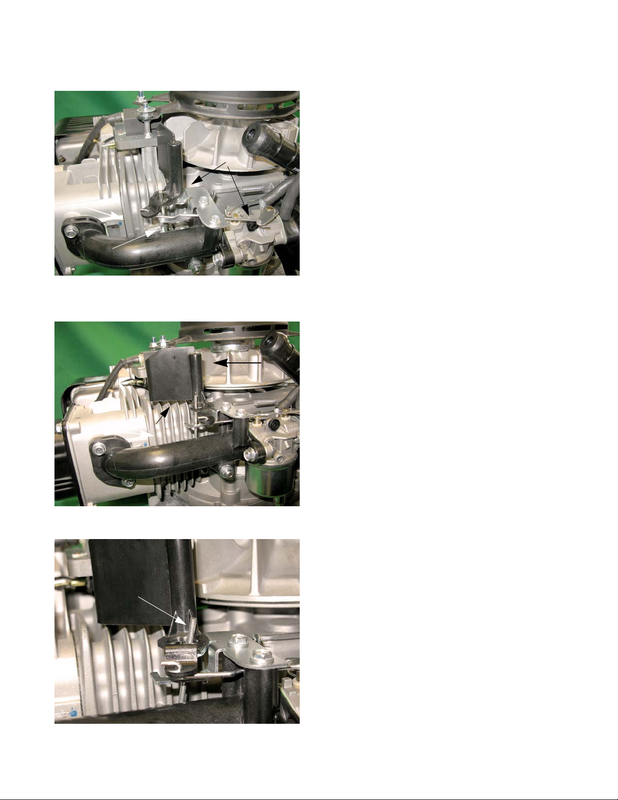
Autochoke
Figure 4.11
Choke
closed
Temperature
compensator
Figure 4.12
Choke
open
Air flow
Figure 4.13
Temperature
compensating rod
in the hot position
FUEL SYSTEM AND GOVERNOR
These engines are equipped with a temperature compensating auto choke. The autochoke system is similar to
the old style air vane governors. When the engine is at rest
a spring holds the choke in the closed position. See
Figure 4.11.
When the engine starts, the air flow from the flywheel
fan pushes on an air vane. The air vane in turn moves the
choke lever, opening the choke. See Figure 4.12.
These engines also have a temperature compensator.
As the engine heats up, a bi-metallic spring expands,
rotating a rod towards the carburetor This rod will override
the autochoke, holding the choke open on hot restarts.
43
Page 50

P71 Series Vertical Shaft Engines
Figure 4.14
Air vane bracket
Figure 4.15
Indent
screw posts
Figure 4.16
Temperature Compe nsator
To remove/replace the air vane:
1. Remove the fuel cap and tether by unscrewing
them. See Figure 4.6.
2. Remove the fuel tank nut.
3. Remove the screw that holds the fuel tank to the
shroud using a 10 mm wrench.
4. Remove the engine cover.
5. Lift the shroud enough to gain access to the charcoal canister.
6. Disconnect the fuel tank vacuum line from the canister.
7. Slide the tank out of the shroud.
8. Remove the two screws that hold the air vane
bracket using an 8 mm wrench. See Figure 4.14.
9. Slide the air vane and bracket of f of the temperature
compensating rod.
10. Disconnect the choke rod.
11. Install by following the above steps in reverse order.
NOTE: When the choke rod is connected properly,
the indented section should be between the
screw posts of the intake manifold pointing
towards the engine block. See Figure 4.15.
Temperature compensator
To remove/replace the temperature compensator:
1. Remove the screw that hold the compensator to the
cylinder using a 10 mm wrench. See Figure 4.16.
2. Slide the compensator rod out of the air vane.
3. Install the compensator by following the previous
steps in reverse order.
NOTE: When installing the compensator, there is a
tab that must be inserted into a notch in the
mounting cavity. See Figure 4.16 inset.
44
Page 51

FUEL SYSTEM AND GOVERNOR
Carburetors
Troubleshooting the carburetor is a process of elimination. If everything else on the engine checks out, the carbu-
retor is probably bad.
NOTE: It is important to perform a compression or leak down te st befor e conde mnin g a car bur etor. An engine
can have a borderline compression reading and not create enough of a vacuum to draw in a sufficient
fuel/air charge.
NOTE: If the engine has border-line compression, a quick test to see if that is the problem is to remove the
spark plug. Squirt a little bit of oil into the combustion chamber to seal the rings. Reinstall the spark
plug. If the engine starts and runs OK, then that was the problem. If it does not start, move on to the
carburetor.
Inspecting the carburetor:
1. Remove the float bowl and check for dirt and/or varnish.
2. Inspect the needle valve and needle valve seat for dirt and/or damage.
3. Inspect the gaskets and O-rings for damage.
4. Inspect the vents and orifices, verify that they are free of debris.
NOTE: If a little cleaning and new gaskets will fix the carburetor, do it. If the carburetor requires extensive
cleaning it is better to replace the carburetor.
IMPORTANT: Never try to mechanically clean orifices. That will damage them and ruin the carburetor.
NOTE: The carburetors used on all vertical shaft engines are similar in design, but differ in calibration.
NOTE: The jet markings (if present) may be used for identification purposes, but the technician should not
attempt to infer orifice sizes from the identification numbers.
NOTE: Installing the wrong main jet, or a carburetor with the wrong main jet will produce performance and
emissions issues.
45
Page 52

P71 Series Vertical Shaft Engines
Figure 4.17
Float bowl
Drain bolt
Bowl screw
Figure 4.18
Float
Float pin
Fuel inlet
Figure 4.19
Float
Needle valve
Hanger
Disassembly and rebuilding the carburetor
1. Clamp off the fuel line to prevent fuel spillage and
disconnect it from the carburetor nipple
2. Drain the fuel into an approved container.
3. Remove and discard the fuel line.
4. Remove the carburetor by following the steps
described in Chapter 3: Air Intake and Filter.
5. Remove the bowl screw using a 10mm wrench. See
Figure 4.17.
NOTE: From this point an assessment can b e made
about the viability of rebuilding the carburetor.
• If extensive corrosion is evident, replace the
carburetor.
• If varnish build-up is too extensive to clean, replace the carburetor.
6. Remove the rubber bowl gasket. See Figure 4.18.
7. Remove the pin that the float hinges on to remove
the float.
NOTE: The float is not adjustable. The needle valve
is suspended from the float by a wire hanger .
See Figure 4.19.
NOTE: Because the needle valve is crucial to the
functioning of the carburetor, and the viton
tip of the valve is subject to wear , it is suggested that technicians replace the valve
float and hanger any time the carburetor is
disassembled for cleaning.
46
Page 53
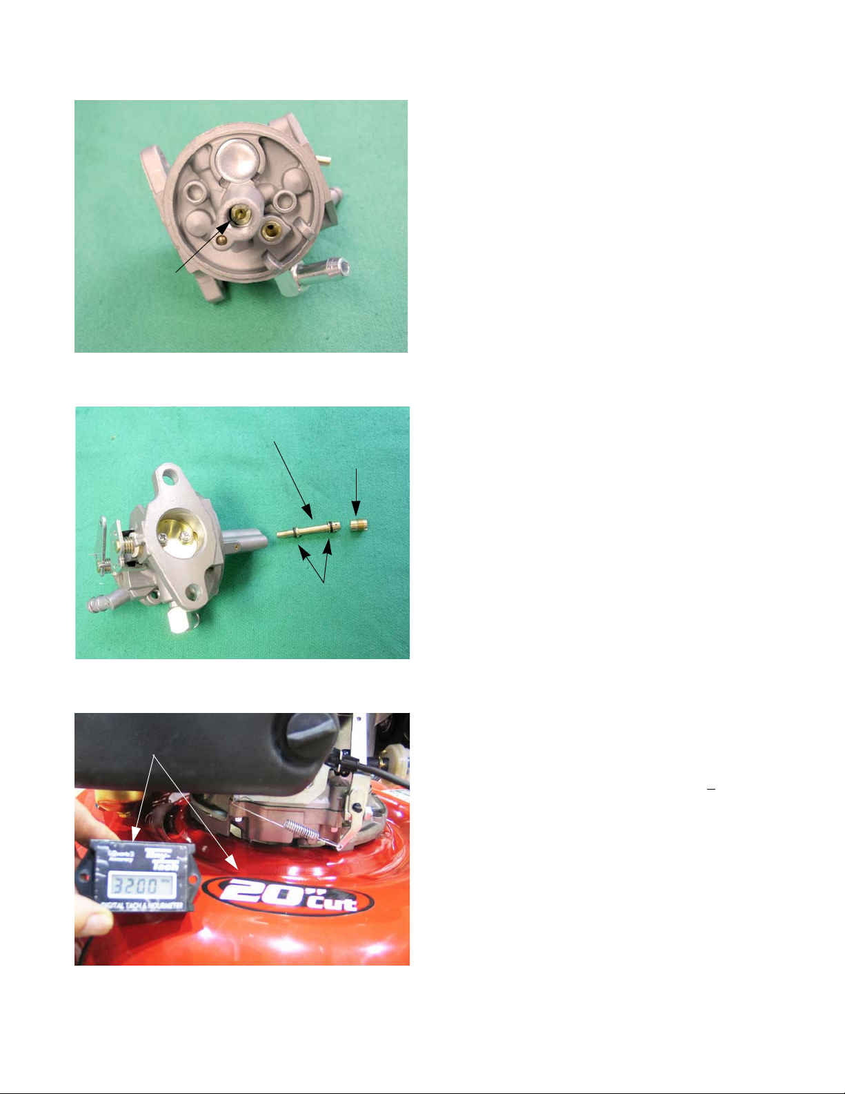
FUEL SYSTEM AND GOVERNOR
Figure 4.20
Main jet
Figure 4.21
Emulsion tube
Main jet
O-rings
Figure 4.22
Digital tachometer confirms safe
operating speed
8. Remove the main jet by using a narrow-shank
straight blade screwdriver. See Figure 4.20.
NOTE: Fuel enters the central column through a port
about 1/2” (1cm) from the bottom, to help prevent
the ingress of any residue in the bottom of the
bowl.
NOTE: The orifice in the main jet meters fuel into the cen-
tral column.
NOTE: Air from the main jet emulsion port enters the cen-
tral column near the top, then gets bubbled
through the emulsion tube into the mete re d fu el
flow to promote atomization.
NOTE: The main jet secures the emulsion tube in the cen-
tral column of the carburetor. See Figure 4.21.
9. Clean the carburetor body in an ultrasonic cleaner.
NOTE: Traditional dips are not recommended.
10. Rinse thoroughly.
11. Dry the carburetor body using compressed air.
12. Reassembly the carburetor and install it by following
steps 1-8 in reverse order.
13. Start engine and check the idle RPM using a tachometer.
NOTE: Idle speed: If applicable, is 1,800 RPM +
set using throttle stop screw. See Figure 4.22.
• For mower applications, the idle speed is not nor-
mally critical because the operator is not prov id e d
with a throttle control.
14. Check the top no load speed of the engine.
See Figure 4.22.
160 RPM,
NOTE: The top no load speed will vary depending on the
application. The specification for it will be listed in
the manual for each application.
47
Page 54
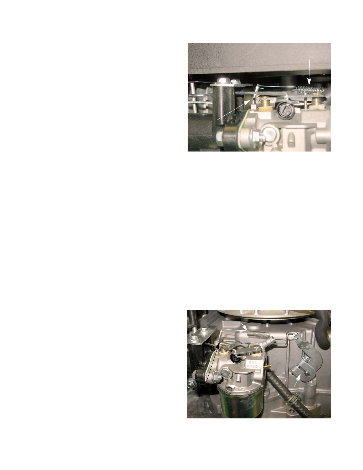
P71 Series Vertical Shaft Engines
Figure 4.23
Increase spring tension to
increase engine speed
Bracket
Governor spring
Figure 4.24
Governor arm
Governor spring
Spring bracket
15. Adjust the top no-load speed by slightly bending the
bracket that the governor spring connects to. The
bracket is visible under the air filter. See Figure
4.23.
Governor
The engine speed is controlled by a balance between
the force applied by a spring (pulling the throttle open) and
a flyweight mechanism within the engine applying force to
the governor arm (pushing the thro ttle clo sed). See Figure
4.24.
NOTE: While the mechanism is simple and robust,
NOTE: When a governed engine “hunts”, it is gen-
48
it is important to pay attention when working
on parts near the governor. Binding caused
by interference with mis-routed lines or
cables may make the governor unresponsive.
erally an indication of a lean fuel/air mixture,
rather than a problem with the governor.
Page 55

Governor arm
Figure 4.25
Nuts
Figure 4.26
Purge hose
Figure 4.27
Clamp screw
FUEL SYSTEM AND GOVERNOR
To remove the governor arm from the governor shaft:
1. Siphon the fuel out of the fuel tank into an approved
container.
2. Remove the oil dipstick.
3. Remove the engine cover.
4. Remove the 3 nuts that hold down the shroud. See
Figure 4.25.
5. Remove the air filter by following the procedures
described in Chapter 3: Air Intake System
6. Disconnect the purge hose from the air filter base.
See Figure 4.26.
7. Lift the shroud and fuel tank as one assembly high
enough to clear the engine and set them beside the
engine.
8. Remove the air filter base by following the procedures described in Chapter 3: Air Intake System.
9. Remove the breather hose.
10. Loosen the governor arm clamp screw with a T-25
Torx driver. See Figure 4.27.
11. Slide the governor arm off of the governor shaft.
12. Unhook the throttle rod and the governor spring.
49
Page 56
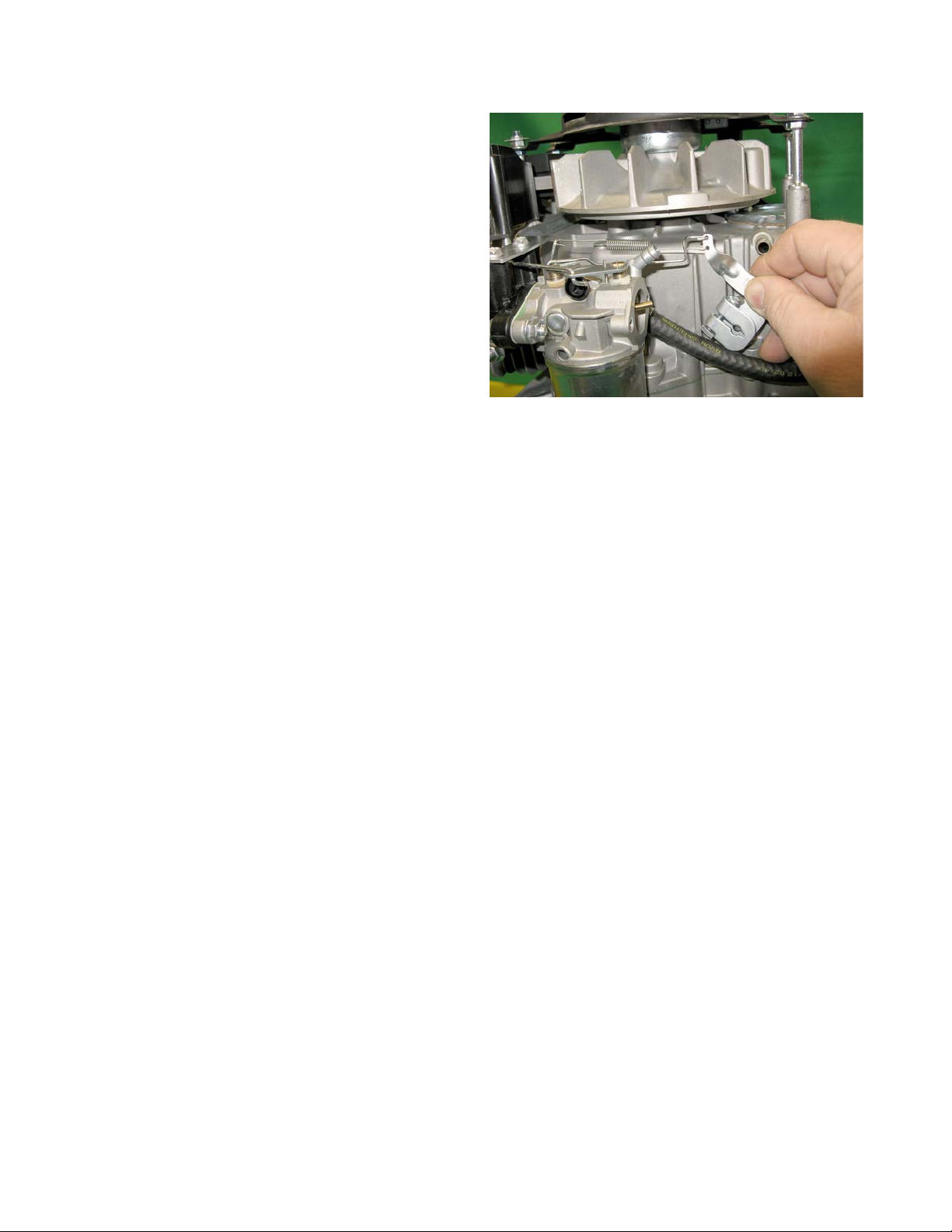
P71 Series Vertical Shaft Engines
Figure 4.28
To install the governor arm:
1. Rotate governor shaft counter clockwise until it
stops.
2. Attach the throttle linkage and governor spring.
3. Position the governor arm over the governor shaft
so that it is holding the throttle plate in the wide
open position. See Figure 4.28.
NOTE: There is a hairpin clip that keeps the gover-
nor shaft from sliding into the engine. It may
be necessary to hold the shaft while sliding
the arm on to prevent it from going into the
engine.
4. Tighten the nut and bolt on the clamp bolt to a
torque of 27 - 44 in lbs (3 - 5 Nm).
5. Install the air filter and its base.
6. Install the engine shroud and fuel tank.
7. Start the engine and check the top no load RPM using a tachometer.
8. Adjust the governor to maintain top no-load spee d as described in the disassembly an d rebuilding the car buretor section of this chapter.
50
Page 57
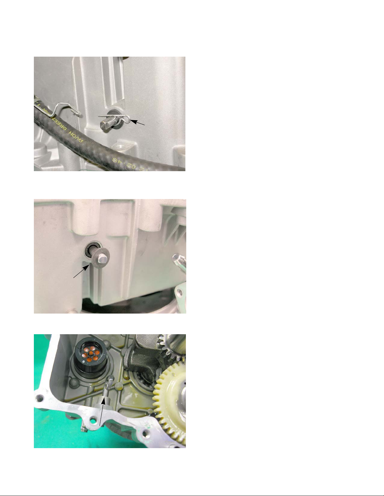
Governor shaft
Figure 4.29
Hairpin clip
Figure 4.30
Flat washer
Figure 4.31
FUEL SYSTEM AND GOVERNOR
To remove or replace the governor shaft:
1. Remove the engine from the unit.
2. Remove the governor arm by following the procedures described in the governor arm section of this
chapter.
3. Remove the sump by following the steps described in
Chapter 10: Disassembly.
4. Remove the hair pin clip from the governor shaft. See
Figure 4.29.
5. Remove the flat washer. See Figure 4.30.
6. Slide the governor shaft out of the engine block from
the inside of the engine. See Figure 4.31.
51
Page 58

P71 Series Vertical Shaft Engines
Figure 4.32
Governor shaft
seal
Figure 4.33
Seal
Cupped side
Figure 4.34
Cam
Bend
7. Remove the governor shaft seal. See Fi gure 4.32.
8. Slide the governor shaft into the engine block from
the inside of the engine.
9. Carefully slide a new seal over the governor shaft
and seat using a 1/4” deep well socket. See Figure
4.33.
NOTE: The cupped side of the seal faces the insi de
of the engine block. See Figure 4.33 inset.
10. Install the hair pin clip.
11. Rotate the governor shaft so that the bent end is
pointing at the cam shaft. See Figure 4.34.
NOTE: If the governor shaft is not pointing at the
cam while sliding the sump on, the governor
shaft will not catch the governor cup.
12. Install the sump by following the procedures
described in Chapter 10: Disassembly.
13. Install the governor arm by following the procedures
described in the governor arm section of this chapter.
14. Install the engine on the unit.
15. Test run the engine and adju st th e to p no load
52
engine rpms by following the steps described in
“Disassembly and rebuilding the carburetor” section
of this chapter.
Page 59

Governor cup, gear and oil slinger
Figure 4.35
Oil slinger gear
Rib
Figure 4.36
Plate
FUEL SYSTEM AND GOVERNOR
The governor gear and cup are driven by the oil sling e r
gear.
NOTE: The governor gear and cup are not serviceable.
To remove/replace the oil slinger gear:
1. Remove the engine from the unit.
2. Remove the sump by following the steps described in
Chapter 10: Disassembly.
3. Remove the screw that hold the slinger gear plate to
the sump using a 10mm wrench. See Figure 4.35.
NOTE: The slinger gear plate is tightly fitted in to a flat
spot on the gear shaft. See Figure 4.36.
4. Remove the slinger gear, shaft and plate as one
assembly.
5. Install by following the previous steps in reverse
order.
NOTE: When installing the slinger gear, the notch on the
plate key onto the rib cast into the sump.
6. Test run the engine and adjust the top no load engine
RPMs by following the steps described in “Disassembly and rebuilding the carburetor” section of this
chapter.
53
Page 60

P71 Series Vertical Shaft Engines
54
Page 61

Lubrication
SAE 40
SAE 30
SAE 10W30/SAE 10W40
SAE 5W20
-4°F
14°F
32°F 50°F 68°F 86°F 104°F
-20°C
-10°C
0°C
10°C 20°C
30°C
40°C
Oil Chart
CHAPTER 5: LUBRICATION
Oil type and quantity
The recommended oil for MTD engines is an SAE 30 oil with an SM API rating or better. The oil capacity is 17.0-
20.3 fl.oz (0.5-0.6 liters).
• If the oil is noticeably thin, or smells of gasoline, carburetor repair may be needed before the engine can
be run safely.
• Check the oil level frequently and change the oil more frequently in severe operating conditions such as
exceptionally deep snow falls.
• Synthetic oil is a suitable alternative, but it does not extend service interva ls.
NOTE: MTD recommends the use of petroleum oil during the break in period to ensure the piston rings cor-
rectly break in.
Synthetic vs. Petroleum based oil: To simply look at synthetic oil and to com pare it with Petroleum based oil there
is very little difference. However, when you look at the two through a microscope it is easy to see the differen ce. Synthetic is made up of smaller molecules. This allows the oil to get into areas that petroleum based oil cannot.
55
Page 62

P71 Series Vertical Shaft Engines
Figure 1.1
Fully seat the
dip stick before
reading it
Figure 5.2
Screw
Figure 5.3
O-ring
Oil dipstick
To check the oil:
1. Twist and remove the dipstick from the engine.
2. Clean the oil off of the tip of the dipstick.
3. Re-insert the dipstick and turn it until it is fully
seated to get the oil level reading. See Figure 1.1.
4. The oil level is determined by the highest point on
the dipstick that is completely covered with oil.
Dip stick tube removal
Some MTD engines come with a dip stick tube, depending
on the application. See Figure 5.2.
To remove/replace the dip stick tube:
1. Remove the dip stick.
2. Remove the screw at the top of the dip stick tube
3. Lift the dip stick tube enough for the bottom of the
4. Pull the tube out of the underside of the engine
5. Inspect the O-ring on the dip stick tube. Replace if
6. Install by following the previous steps in reverse
using a 10 mm wrench. See Figure 5.2.
tube to clear the engine block.
shroud.
damaged. See Figure 5.3.
order.
56
Page 63

Lubrication system
Figure 5.4
Paddles
Slinger gear
Figure 5.5
Figure 5.6
Oil return port
Supply passage
Lubrication
MTD uses a splash lube system for it’s vertical shaft
engines. The oil slinger gear has paddles on it that
“splashes” oil around the inside of the engine. See Figure
5.4.
The splashing action will also atomize or change the oil
into a mist. There are two oil passages that run along the
engine cylinder. The one just above the oil line is the oil
supply passage. The oil mist will flow through this passage
to the cylinder head. The supply passage lines up with the
top crank arm so that some of the oil on the crank arm will
be flung into the supply passage, forcing additional oil up
to the cylinder head. See Figure 5.5.
The second oil passage is located between the tappet s.
This is the oil return passage. As the name implies, it
allows the oil collecting in the cylinder head to return to the
sump. See Figure 5.6.
NOTE: Because these engines use splash lubrication, the
type of oil and the oil level is critical for proper
operation of the engine. If the oil level is too low,
the paddles on the governor gear can not splash
the oil into the engine. If the oil level is too high, the
oil will not change into a mist to reach the upper
side of the engine.
57
Page 64

P71 Series Vertical Shaft Engines
Figure 5.7
PCV valve cover
Figure 5.8
Foam insert
Figure 5.9
Breather body
PCV
The PCV valve is located under the flywheel an d allows
the crankcase pressure to escape. The function and test
procedures for the PCV is covered in Chapter 2: Basic
Troubleshooting.
To service the PCV:
1. Remove the flywheel by following the steps
described in the Chapter 7: Ignition System.
2. Remove PCV valve cover using a T-30 Torx driver.
See Figure 5.7.
3. Remove the foam insert. See Figure 5.8.
4. Insert a long nosed pair of pliers into the breather
body
5. Open the plier wide enough that they press against
the inside walls of the breather body while pulling
the chamber out of the engine block. See Figure
5.9.
58
Page 65
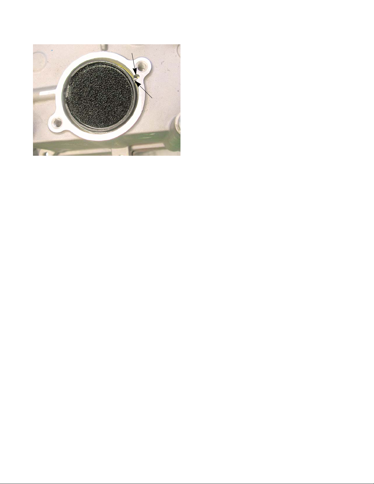
Lubrication
Figure 5.10
Notch
Rib
6. Insert a breather body, with the foam insert and a
new O-ring.
NOTE: There is a rib on the breather body that fits into a
notch in the engine block. See Figure 5.10.
7. Install the PCV valve cover with a new gasket.
Tighten the cover screws to a torque of 62 - 80 in lbs.
(7 - 9 Nm).
8. Inspect the breather tubing for cracks, brittleness or
signs of leaking. Replace the breather tube if any are
found.
9. Install the flywheel and engine shroud by following
the procedures described in Chapter 7: Ignition System.
10. Test run the engine before returning to service.
59
Page 66

P71 Series Vertical Shaft Engines
60
Page 67

Engine shroud removal
Figure 6.1
Bib
Full
Figure 6.2
Unsnap
Starters
CHAPTER 6: STARTERS
To remove recoil assembly from the engine:
1. Remove the engine cover:
NOTE: There are two types of engine covers: See Figure
6.1.
• Full cover
• Bib cover
Full cover
1a. Unsnap the front of the cover from the engine
shroud. See Figure 6.2.
1b. Unhook the rear of the cover from the shroud.
Bib cover
1a. Using a thin, flat blade push in the front tab of
the bib cover enough to unsnap it from the
shroud.
1b. Unhook the rear of the cover from the shroud.
61
Page 68
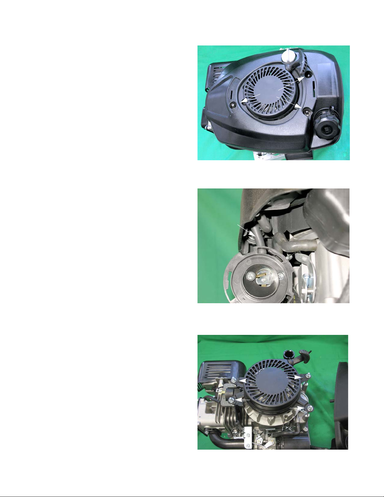
P71 Series Vertical Shaft Engines
Figure 6.3
Nuts
Figure 6.4
Purge hose
Figure 6.5
2. Remove the oil dipstick.
3. Remove the 3 nuts that hold down the shroud. See
Figure 6.3.
4. Remove the air filter by following the procedures
described in Chapter 3: Air Intake System
5. Disconnect the purge hose from the air filter base.
6. Lift the shroud and fuel tank as one assembly high
7. Install the shroud by following the previous steps in
Recoil starter removal/replacement
1. Remove the engine shroud by following the steps
2. Remove the four nuts that secure the recoil assem-
3. Lift the recoil assembly off of the engine.
4. Install the starter by following the previous steps in
See Figure 6.4.
enough to clear the engine and set them beside th e
engine.
NOTE: The fuel tank is still connected to the carbu-
retor by the fuel line.
reverse order.
NOTE: Tighten the engine shroud nuts to a torque
of 62 - 80 in lbs (7 - 9 Nm).
described in the previous section of this chapter.
bly to the engine using a 10mm wrench. See Figure
6.2.
reverse order.
NOTE: Tighten the recoil starter nuts to a torque of
62 - 80 in lbs (7 - 9 Nm).
5. Test run the engine in a safe area before returning it
to service.
62
Page 69
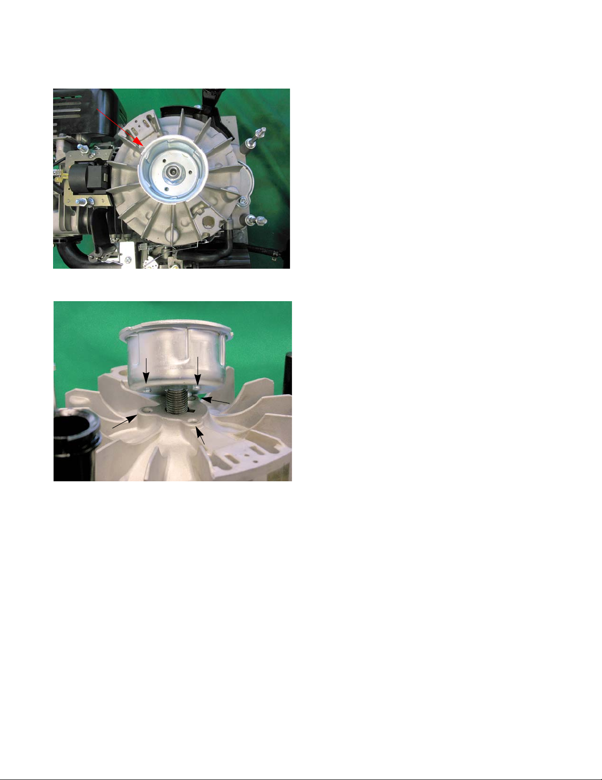
Starter Cup
Figure 6.6
Starter cup
Figure 6.7
Starters
1. Remove the recoil starter by following the procedures
described int the recoil starter section of this chapter.
2. Inspect the inside of the starter cup. See Figure 6.6.
NOTE: If the starter was failing to engage the flywheel,
and the edges of the teeth inside the cup are
rounded, replace the starter cup.
NOTE: If the starter cup is replaced, the complete starter
should be replaced as well, to prevent a repeat failure.
3. Lock the engine using a piston stop or a strap
wrench.
4. Remove the flywheel nut Using a 19 mm wrench.
5. Install a starter cup by placing the star ter cup on the
flywheel allowing the protrusion on the bottom of the
starter cup to rest inside the dimple in the flywheel.
See Figure 6.7.
6. Install the flywheel nut and tighten it to a torq ue of 37
- 41 ft-lbs (50 - 55 Nm).
7. Install the recoil starter and engine shroud.
8. Test run the engine in a safe area before returning it
to service.
63
Page 70

P71 Series Vertical Shaft Engines
Figure 6.8
Starter cord knot
Figure 6.9
Spring clamp
maintains tension
while rope
is installed
Press knot
fully into
groove
Figure 6.10
Inset: knot
Starter Rope
The most common failure mode for most recoil assemblies is a broken rope. See Figure 6.8.
NOTE: If the spring was not damaged when the
recoil sprung back, it is possible to simply
remove the remnants of the old rope.
1. Remove the starter by following the step s described
earlier in this chapter.
2. Remove the old starter rope by prying out the st arter
cord knot and pulling the rope out with it.
3. Cut a piece of #4 recoil rope 9’ (3 meters) long.
4. Heat fuse the ends of the starter rope, and tie a double half-hitch in one end.
5. The rope may be easily installed from the insideout. Pull the rope tight to seat the knot firmly in the
recess in the back of the pulley. See Figure 6.9.
6. Wind the spring completely . Then rel ieve it minimum
7. Install the handle and handle insert on the loose end
8. Remove the spring clamp and carefully let the rope
9. Give the starter a couple of test pulls to verify the
1 full turn, counting when the pulley knot aligns with
the rope bushing in the housing. (This usually
results in about 1.5-1.75 complete turns of relief),
and secure it with a spring clamp. See Figure 6.9.
of the rope, again using a double half-hitch. See
Figure 6.10.
rewind into the starter.
right amount of tension on the starter rope.
64
Page 71
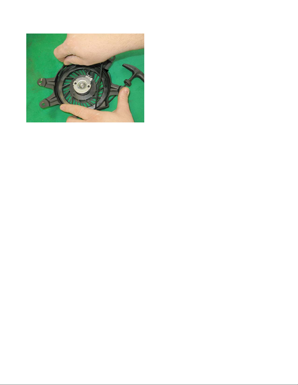
Starters
Figure 6.11
Rope-return tension may
be increased by winding
the rope and pulley
counter clockwise.
NOTE: If starter rope tension needs to be adjusted, there
is room between the recoil housing and the pu lley
to wind-on more tension. See Figure 6.11.
10. Install the starter and tighten the starter nuts to a
torque of 80-106 in-lbs (9-12 Nm).
65
Page 72
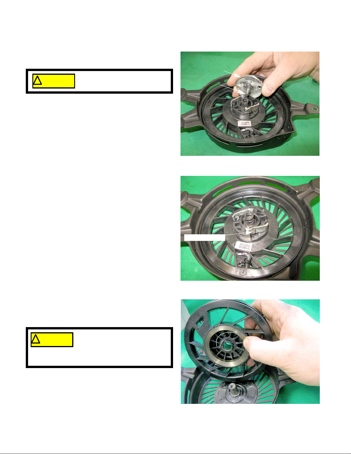
P71 Series Vertical Shaft Engines
Figure 6.12
Pressure plate
Shoulder screw
Eye protection should be worn if
the starter pulley is to be removed.
! CA UTION! CA UTION
Figure 6.13
Torsion spring
Figure 6.14
Eye protection should be worn if the
starter pulley is to be removed.
The recoil spring is under tension
and can release as the pulley is removed.
! CA UTION! CA UTION
Starter pulley and recoil spring
The recoil spring is nested within the starter pulley and
both parts are assembled as a single part number.
If damage is suspected, the recoil may be disassembled by:
1. Remove the starter by following the step s described
earlier in this chapter.
2. Remove the shoulder screw and pressure plate
using a 10 mm wrench. See Figure 6.12.
NOTE: Beneath the pressure plate is a compres-
sion spring, and two starter pawls that are
held in the disengaged position by two torsion springs.
3. Inspect the pawls and torsion springs for wear and
4. Carefully lift the spring and pulley out of the recoil
damage. See Figure 6.13.
housing. See Figure 6.14.
66
Page 73
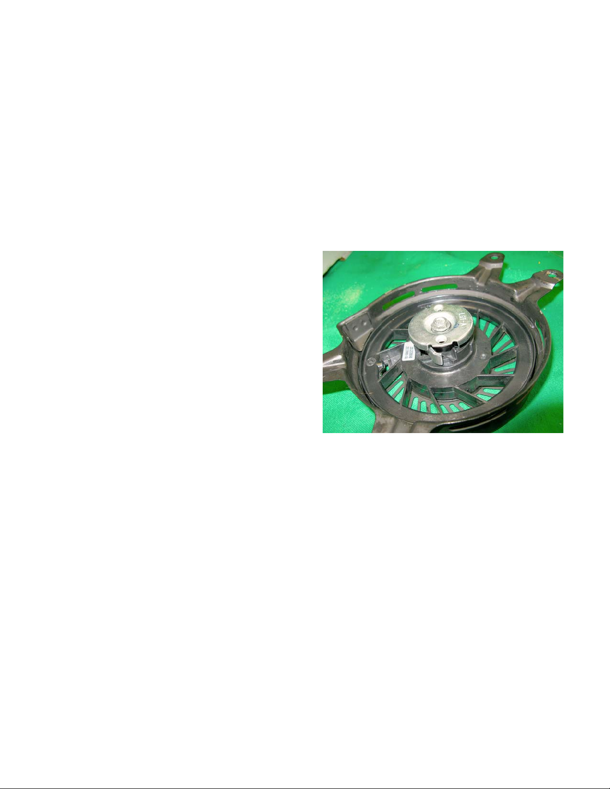
Starters
Figure 6.15
NOTE: If the spring is undamaged, but has been removed from the pulley, the spring may be re-wound.
Engage the hook in the end of the spring with the slot in the o uter lip of the re cess that the spr ing fits in,
and wind the spring into the recess in a counter-clockwise direction.
NOTE: Evaluate the damage, including part s costs and local labor rates. In some parts of the country, it makes
economic sense to replace the complete assembly, in other areas labor rates favor repair.
5. To re-assemble, apply a small amount of lithium-based chassis grease to the surface of the recoil h ousing that
contacts the spring.
6. Carefully position the pulley and spring in the recoil housing. Rotate the pulley gently counter-clockwise until
the spring seats, allowing the pulley to fall into position.
7. Install the torsion springs and pawls so that the long arm of th e spri ng reache s outside of the pawl, and draws
it toward the center of the assembly. See Figure 6.15.
NOTE: The rolled end of the pawl fits in the recess
in the starter pulley. T h e ho o ked en d
engages the starter cup. Both the roll and
the hook face inward.
NOTE: The extrusions on the pressure plate should
fall inside of the pawls as the starter is
assembled.
NOTE: Drag on the pressure plate, from the friction
between the compression spring and the
head of the shoulder screw causes these
extrusions to force the pawls outward,
engaging the starter cup.
8. Apply a small amount of thread locking compound
such as Loctite 242 (blue) to the threads of the
shoulder screw , and install the scre w . T ighten it to a
torque of 71 - 89 in-lb. (8 - 10 Nm).
9. Install the starter rope by following the steps described in the previous section of this chapter.
10. Install the starter and tighten the starter nuts to a torque of 80-106 in-lbs (9-12 Nm).
67
Page 74

P71 Series Vertical Shaft Engines
Figure 6.16
Figure 6.17
Ring Gear
Figure 6.18
Ground wire
Electric starter
To remove/replace the electric starter:
1. Remove the shroud by following the procedures
described in the Engine Shroud Removal section of
this chapter.
2. Disconnect the starter harness.
3. Remove the two nuts the hold the starter cover to
the starter, using an 8 mm wrench. See Figure 6.16.
4. Lift the cover off of the engine.
5. Remove the dip stick tube.
6. Remove the two screws that secure the starter to
the engine block, using a 10mm wrench. See Figure
6.17.
NOTE: The ring gear is cast into the flywheel.
NOTE: The ground wire is attached to the lower
front starter screw. See Figure 6.18.
7. Install the starter by following the previous steps in
reverse order.
8. Test run the engine befor e re tur n ing it to serv ice.
68
Page 75

Starter Interlock Switch
Figure 6.19
Starter Interlock Switch
Wires
Figure 6.20
Cable Bracket
Screw head
Starters
On engines equipped with an electric starter, there is a
Starter Interlock Switch mounted on to the engine brake
assembly . The interlock switch prevent s power from re aching the electric starter unless the safety bail is depressed
or the engine brake is released.
To remove/replace the Starter Interlock Switch:
1. Remove the Engine brake assembly by following the
procedures described in Chapter 7: Ignition System.
2. Disconnect the switch wires. See Figure 6.19.
3. Squeeze the cable bracket and the brak e un til the
lower switch screw’s head is fully accessible through
the access hole in the cable bracket. See Figure
6.20.
4. Remove the two mounting screws and nuts using a
#2 Phillips screwdriver and a 5.5 mm wrench.
5. Install the switch by following the previous steps in
reverse order.
NOTE: The order of the wires on the interlock switch does
not matter. If the wires are reversed, it will not
affect the operation of the circuit.
6. Test run the engine in a safe area and verify that the
engine brake assembly stops the engine within 3
seconds before returning the engine to service.
69
Page 76

P71 Series Vertical Shaft Engines
Schematic
70
Page 77

Troubleshooting the ignition system
Figure 7.1
Spark tester
! CAUTION! CAUTION
Never remove the spark plug and
hold it against the cylinder head to
test for spark. The fuel/air mix com-
ing out of the spark plug hole will catch on fire.
Ignition System
CHAPTER 7: IGNITION SYSTEM
The purpose of the ignition system is to provide a spark
in the combustion chamber at the proper time to efficiently
ignite the fuel/air mixture. The steps in troubleshooti ng the
ignition system are:
1. Examine the spark plug(s) by following the steps
described in the spark plug section of this chapter.
NOTE: It is convenient to check the compre ssion when the
spark plug is removed for examination.
2. Connect a spark tester between the spark plug wire
and a good ground point on the engine.
See Figure 7.1.
NOTE: Do not connect the spark tester to the spark plug
when testing for ignition.
NOTE: It only takes 1,000 volts to jump a 0.025” a ir gap in o pen atmo sp her e, it takes 10,000 volts to jump the
same gap at 120 psi; therefore, an open air spark test is not valid.
NOTE: The spark should be a minimum of 10 Kv (10,000 volts) at pull over speed.
3. Move the throttle lever to the full throttle position (if equipped).
4. Squeeze the safety bail (if equipped), and pull the starter rope. If sparks ca n be seen in the spark tester, the
ignition system is working.
NOTE: If there are sparks present in the spark tester, install a known-good spark plug and prime test the
engine. If the engine does not start, check the fly wheel key. If the fly wheel key is intact, the problem is
not in the ignition system. Check the engine’s compression.
5. If no sparks or weak sparks are seen in the spark tester, check the module air gap.
NOTE: If the module air gap is correct, further testing is required.
6. Unplug the wire that connects the ignition module primary windings to a ground for engine shut down.
7. Re-test for sparks.
• If there are no sparks, the module is bad or the flywheel magnets have lost their magnetism (very rare).
• If there are sparks, troubleshoot the stop switch.
71
Page 78

P71 Series Vertical Shaft Engines
Figure 7.2
Lead from stop switch
Figure 7.3
Safety bail squeezed
Troubleshooting the stop switch
To test the stop switch:
1. Remove the engine shroud.
2. Unplug the wire from the spade terminal on the
module.
3. Connect one probe of a Digital MultiMeter (DMM) to
the lead disconnected from the module.
4. Connect the other probe to a good ground point on
the engine.
5. Set the DMM to measure resistance.
NOTE: The reading should be near zero when the
bail released. A high reading (>1) is an
indication the switch may have burnt contacts. See Figure 7.2.
6. Squeeze the safety bail.
NOTE: Resistance (Ohms) should be infinite (O.L).
See Figure 7.3.
NOTE: If there is continuity to ground, the stop
NOTE: The lead going to the module is part of the
switch is shorted to ground.
stop switch, if there is a short replace the
whole switch assembly.
72
Page 79

Troubleshooting the flywheel
Figure 7.4
Magnets
Figure 7.5
Figure 7.6
Flywheel key
Ignition System
To Troubleshoot the flywheel:
1. Remove the engine shroud.
NOTE: Failure of the magnets in the flywheel is exceed-
ingly rare.
2. Test the magnets by holding an item made of ferrous
metal roughly 1/4” (.635cm) away from the magnets
in the flywheel. See Figure 7.4.
NOTE: It should be drawn to the flywheel. A wrench or
screwdriver is suitable for this test.
3. Check the polarity of the magnets using a magnetic
compass or bar magnet.
NOTE: The magnets must be installed opposite magnetic
poles facing out. See Figure 7.5.
4. Remove the recoil assembly by following the steps
describe in Chapter 6: Starter.
5. Remove the flywheel by following the steps
described in the flywheel section of this chapter.
6. Inspect the flywheel key and the keyway on the crank
shaft.
NOTE: A sheared flywheel key will throw off the ignition
timing.
NOTE: If the flywheel key is damaged, replace it. If the
keyway on the crankshaft is damaged, the engine
must be short blocked.
73
Page 80
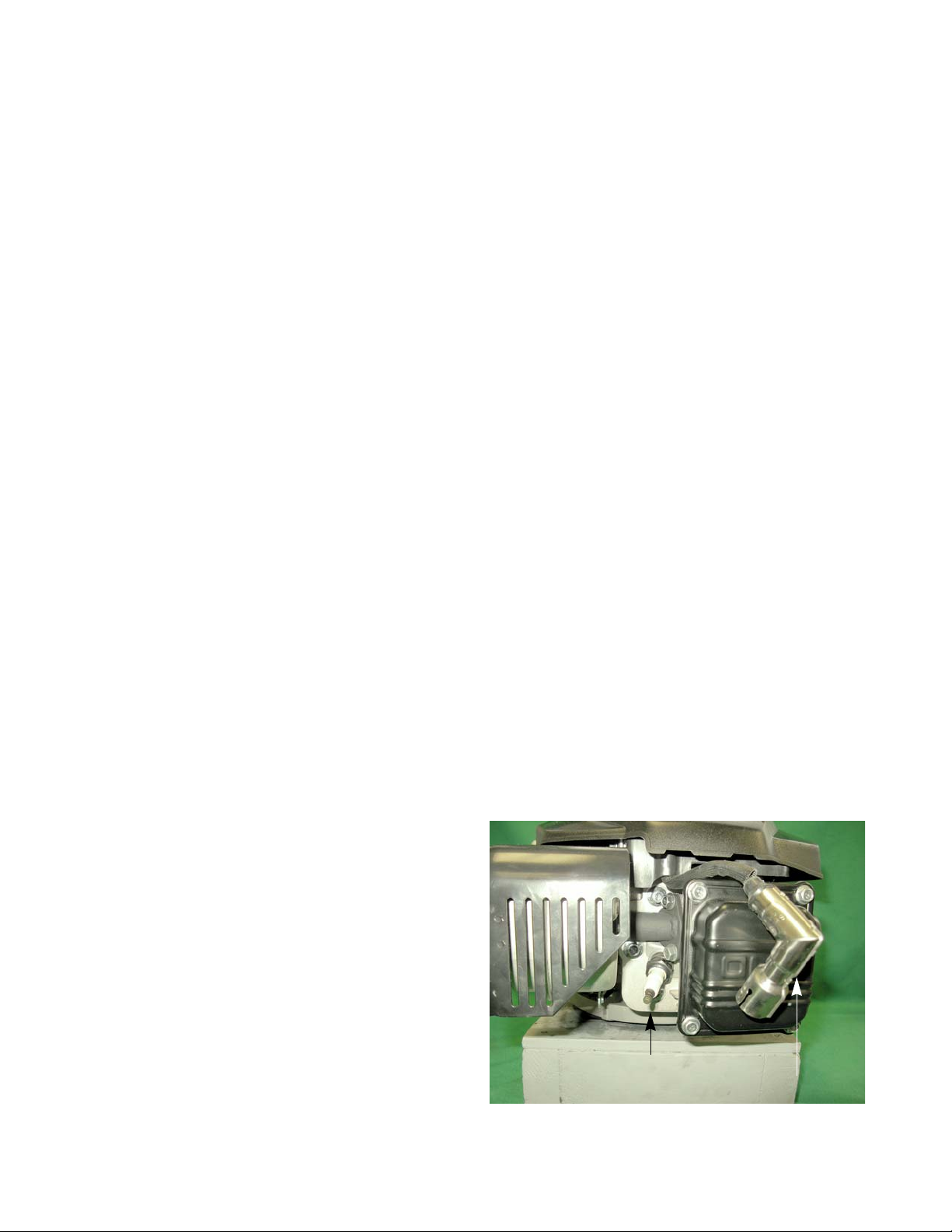
P71 Series Vertical Shaft Engines
Figure 7.7
High tension lead
Spark plug
Spark plug
• The spark plug is a F6RTC, part #951-10292, gapped to 0.024” - 0.031” (0.6 - 0.8 mm).
• Wear rate will vary somewhat with severity of use. If the edges of the center electrode are rounded-off, or
any other apparent wear / damage occurs, replace the spark plug before operating failure (no start)
occurs.
Cleaning the spark plug
• Cleaning the spark plug is not recommended. If the plug needs to be cleaned, replace it.
• Use of a wire brush may leave metal deposits on the insulator that cause the spark plug to short-out and
fail to spark.
• Use of abrasive blast for cleaning may damage the ceramic insulator or leave blast media in the recesses
of the spark plug. When the media comes loose during engine operation, severe and non-warrantable
engine damage may result.
Inspection of the spark plug
Inspection of the spark plug can provide indications of th e op er a ting con d ition of th e en gin e .
• Light tan colored deposits on insulator and electrode s is nor mal.
• Dry , black deposits on the insulator and electrodes indicate an over-rich fuel / air mixture (too much fuel or
not enough air)
• Wet, black deposits on the insulator and electrodes indicate the presence of oil in the combustion chamber.
• Heat damaged (melted electrodes / cracked insulator / metal transfer deposits) may indicate detonation.
• A spark plug that is wet with fuel indicates that fuel is present in the combustion chamber, but it is not
being ignited.
Spark plug removal
1. Disconnect and ground the spark plug wire.
2. Remove the spark plug using a 13/16” or 21mm
wrench. A flexible coupling or “wobbly” extension
may help. See Figure 7.7.
3. Gap a new spark plug to 0.024” - 0.031” (0.60 - 0.80
mm).
4. Install the new spark plug and tighten to a torque of
15 - 18.5 ft - lbs (20 - 25 Nm).
74
Page 81

Ignition System
Figure 7.8
Unplug the wire
Remove the studs
Figure 7.9
0.012” feeler
gauge
Ignition module
The ignition system is a capacitive discharge ignition system, contained in a single module.
• The capacitive discharge has a three leg design.
• The magneto is energized by the passing of a pair of magnets mounted in the flywheel.
• Ignition timing is set by the location of the flywheel in relation to the crankshaft. Proper timing is maintained by a steel key.
Module removal
1. Unplug the spark plug.
2. Remove the recoil assembly by following the steps
described in Chapter 6: Starter.
3. Lift the fan shroud off of the three studs that locate it.
4. Unplug the wire from the spade terminal on the module. See Figure 7.8.
5. Remove the studs holding the module in place using
a 10mm wrench.
Installing the module and setting the air gap
1. Rotate the flywheel so that the magnets are away
2. Install the module. Do not tighten the module down.
3. Place a non-ferrous feeler gauge between the mod-
4. Rotate the flywheel so that the magnets align with
5. Tighten the module mounting screws to a torque of
6. Rotate the flywheel to remove the feeler gauge.
7. Install the blower housing and starter.
8. Connect the spark plug wire to the spark plug.
NOTE: If just setting the air gap, loosen the module
mounting screws first then follow the same
steps as described below.
from where the module is mounted.
ule and the flywheel. See Figure 7.9.
NOTE: The air gap should be 0.012” - 0.020” (0.3 -
0.5 mm).
the legs of the module while holding the feeler
gauge in place.
18.5 ft-lbs (10Nm).
9. Test run the engine before returning to service.
75
Page 82
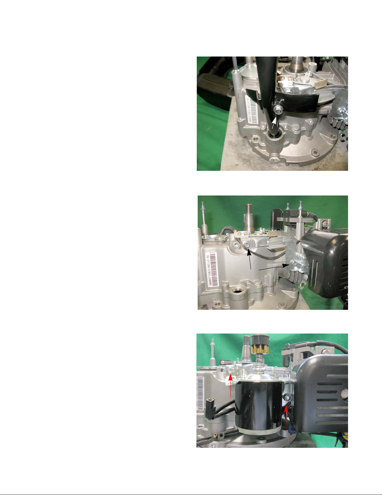
P71 Series Vertical Shaft Engines
Figure 7.10
Figure 7.11
Screws
Figure 7.12
Engine brake and stop switch (if equipped)
NOTE: The stop switch and brake (for lawn mower
applications) must be able to stop the blade
from rotating within 3.0 seconds after the
release of the safety bail, per ANSI B71.12003 standard.
NOTE: The brake should be replaced w hen th e
thickness of the pad is less than 0.060”
(1.524 mm) at the thinnest spot.
To replace the brake assembly:
1. Disconnect and ground the spark plug wire.
2. Remove the recoil assembly and engine shroud by
following the steps described in Chapter 6: Starter.
3. Remove the flywheel by following the steps
described in the flywheel section of this chapter.
NOTE: Inspect the inside of the flywheel, where the
brake rides, for any signs of damage or
wear.
4. Disconnect the engine control cable.
5. Remove the screw that holds the dip stick tube to
the engine block using a 10 mm wrench. See Figu re
7.10.
6. Lift the dipstick tube off of the engine.
7. Disconnect the stop switch lead from the module.
8. Remove the two screws securing the brake assembly. See Figure 7.11.
NOTE: On engines equipped with an electric starter ,
the starter mounting screws hold the brake
assembly in place. Remove the starter to
remove the brake assembly. See Figure
7.12.
9. Install the brake by following the previous steps in
reverse order.
10. Test run the engine in a safe area before returning it
to service.
76
Page 83
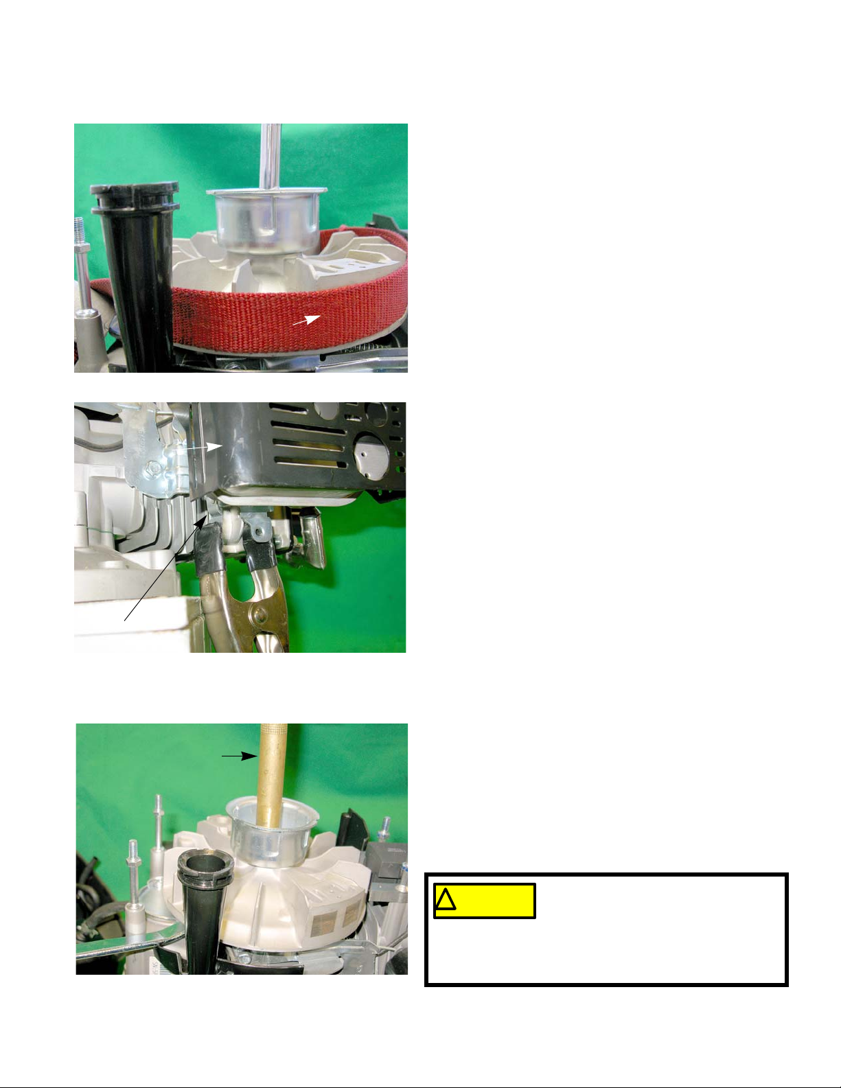
Flywheel
Figure 7.13
Strap wrench
Figure 7.14
Engine brake lever
Muffler
Figure 7.15
Brass punch
! CAUTION! CAUTION
If the flywheel shows any signs of
physical damage such as cracks, bro-
ken vanes (if equipped), or a damaged
keyway, replace it. A damaged flywheel poses a
threat of a burst failure. Burst failures are extremely
hazardous to surrounding people and property.
Ignition System
To remove the flywheel:
1. Remove the recoil assembly and the engine shroud
by following the steps described in Chapter 6: Starter.
2. Lock the engine to prevent it from turning.
3. Loosen the flywheel nut until it is a couple of threads
past the end of the crank shaft using a 19mm
wrench. See Figure 7.13.
NOTE: If equipped with an engine brake, clamp off the
brake using a spring clamp. See Figure 7.14.
NOTE: If equipped with an electric starter, remove the
module by following the procedures described in
the Ignition Module section of this chapter.
4. Remove the flywheel by applying a sharp blow to the
crankshaft using a brass drift punch and a hammer
while gently prying with a prybar. The flywheel will
“pop” loose then lift it off.
NOTE: Never strike the crankshaft directly with a hammer.
To prevent damage to the crankshaft use a brass
drift punch or a piece of wood between the hammer and the crankshaft. See Figure 7.15.
77
Page 84
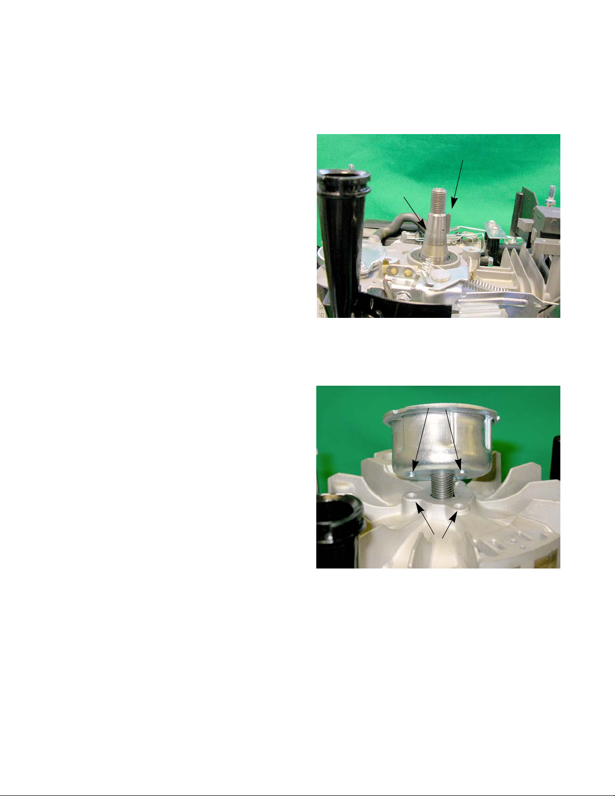
P71 Series Vertical Shaft Engines
Figure 7.16
Key flat parallel to the threads
Taper
Figure 7.17
Starter cup protrusions
Flywheel dimple
5. Inspect the key, keyway, and tapered mating surfaces of the flywheel and crankshaft. See Figure
7.16.
NOTE: If the key is damaged it must be replaced. If
there is damage to the crankshaft key way,
the engine must be short blocked because
crankshafts are not available as a service
part.
IMPORTANT: The taper in flywheel and the on the
crankshaft must be clean and dry.
The flywheel is held in place by the
friction fit between the flywheel and
the crankshaft, not the key. The key
is only to guide the flywheel to the
proper position until it is torqued
down.
6. On installation, confirm that the key is properly
seated (the flat of the key parallel with the threaded
section of the crankshaft) in the key-way, and that
the tapers are fully seated. Key or keyway failure
may result from improper seating.
7. Install a starter cup by placing the st arter cup on the
flywheel. Allow the protrusions on the bottom of the
starter cup to rest inside the dimples in the flywheel.
See Figure 7.17.
8. Install the flywheel nut to a torque of 33 - 41 ft lbs
(45 - 55 Nm).
9. If removed, install the ignition module by following
the procedures described in the Ignition Module
section of this chapter.
10. Adjust the air gap by following the steps described
in the ignition module section of this chapter.
11. Reassemble the engine.
12. Test run the engine in a safe area before returning it
to service.
78
Page 85
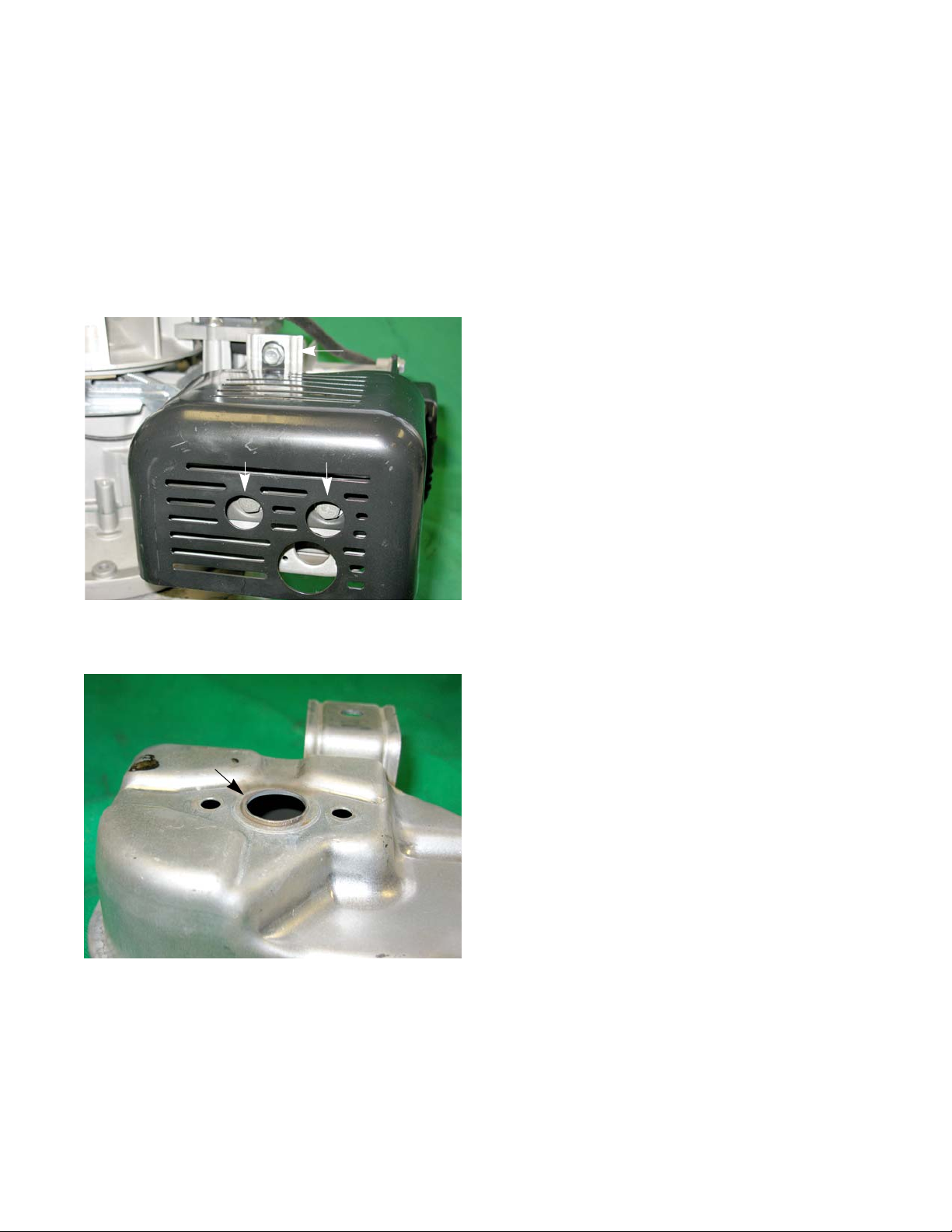
Exhaust
Figure 8.1
Shoulder bolts
Screw
Figure 8.2
Lip
CHAPTER 8: EXHAUST
Muffler
The exhaust system is a frequently overlooked component of an engine. It is important to make sure the muffler
is in good condition and free of debris and/or insects.
NOTE: A blocked muffler will result in poor performance. If a muff ler is completely blocked, the engine may not
start.
To remove/replace the muffler:
1. Remove the engine shroud by following the procedures described in Chapter 6: Starters.
2. Remove the two shoulder bolts that hold the muffler
to the exhaust manifold using a 13 mm wrench. See
Figure 8.1.
3. Remove the screw that holds the muffler and its
guard to the cylinder head using a 10 mm wrench.
4. Pull the muffler off of the manifold.
NOTE: The muffler does no t have a gasket b etween it and
the manifold. The muffler has a lip that will expand
into the manifold as it heats up. See Figure 8.2.
5. Install the muffler by following the previous steps in
reverse order.
NOTE: Make sure the muffler is fully seated into the mani-
fold before tightening the shoulder screws.
NOTE: Tighten the m uf fler shou lder bolt s to a torq ue of 62
- 80 in lbs (7 - 9 Nm).
6. Test run the engine before returning to service.
79
Page 86
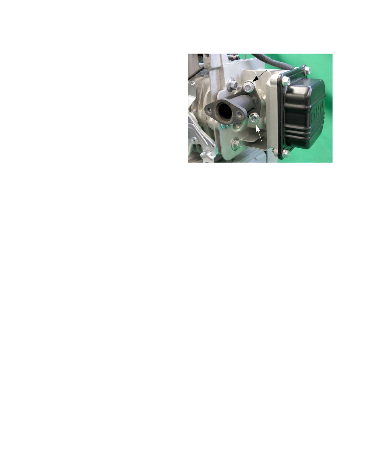
P71 Series Vertical Shaft Engines
Figure 8.3
Exhaust manifold
To remove/replace the exhaust manifold:
1. Remove the muffler by following the procedures
described in the previous section.
2. Remove the manifold screws using a 10 mm
wrench. See Figure 8.3.
3. Clean the cylinder head and muffler of any residual
gasket material.
NOTE: The exhaust gasket is made of a graphite
material. It will stick to the sealing surfaces
when pressure is applied, tearing when
pressure is relieved. The gasket can only be
used one time.
4. Using a new gasket, install the manifold by following
the above steps in reverse order.
NOTE: Tighten the manifold screws to a torque of
80 - 106 in-lbs (9 - 12 Nm).
5. Test run the engine before returning to service.
80
Page 87
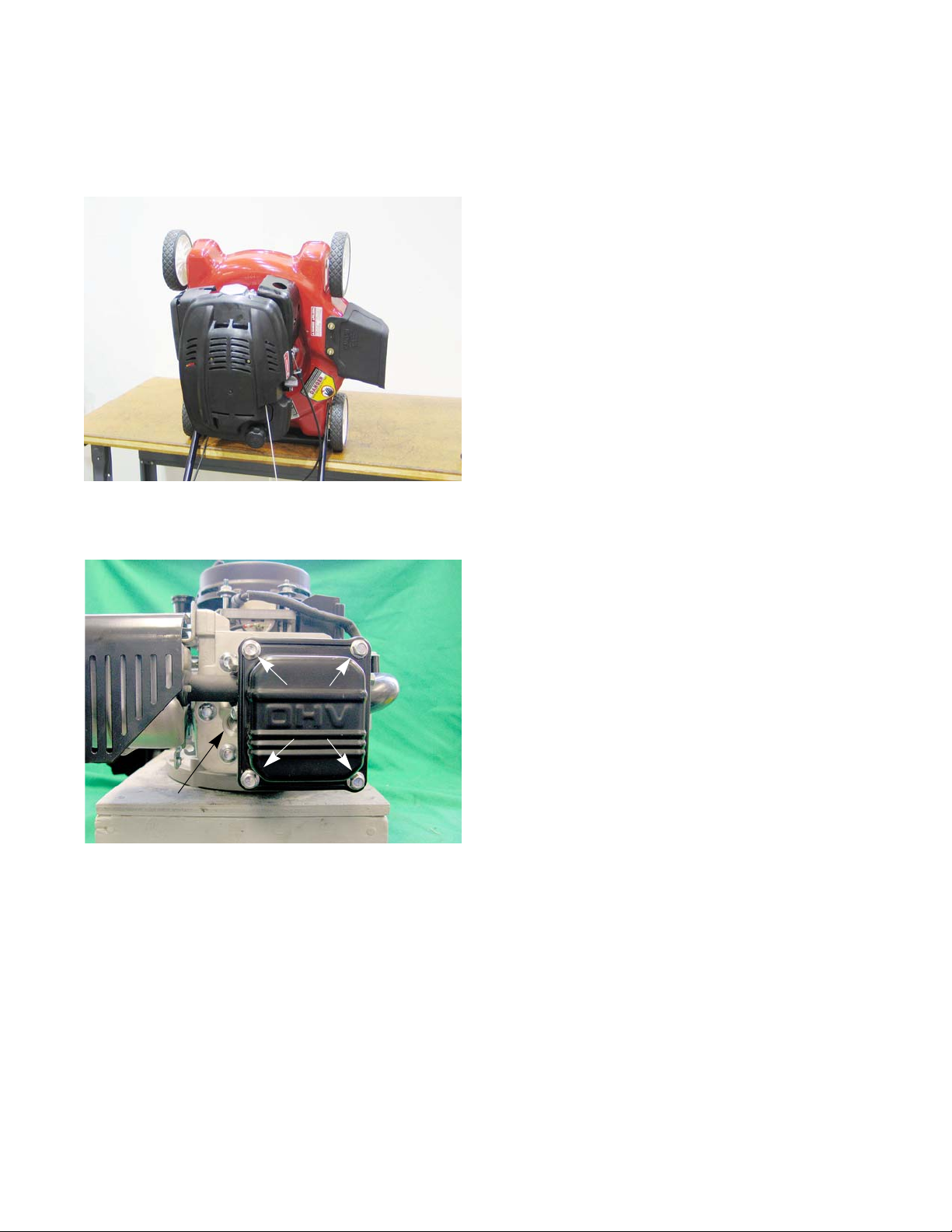
Figure 9.1
Figure 9.2
Valve cover
screws
Spark plug
removed
CHAPTER 9: CYLINDER HEAD
The Cylinder head of the MTD engine can be removed
without removing the engine from the application.
To remove the cylinder head:
NOTE: If possible, it is recommended that the machine be
positioned on the bench so that the cylinder head
is vertical for removal. See Figure 9.1.
NOTE: This position provides easy a ccess to most service
points, yet prevents undue oil spillage.
NOTE: Do not store the engine in this position for a long
period of time. The oil will seep into the breather
chamber.
Cylinder head
1. Disconnect and ground the spark plug high tension
lead.
2. Remove the engine shroud by following the procedures described in Chapter 6: Starters
3. Remove the spark plug using a 13/16” or 21mm
wrench. See Figure 9.2.
4. Rotate the crankshaft until it is at TDC of the compression stroke by following the steps described in
the valve lash section of Chapter 1: Introduction.
5. Remove the four screws securing the valve cover
using a 10mm wrench. See Figure 9.2.
81
Page 88
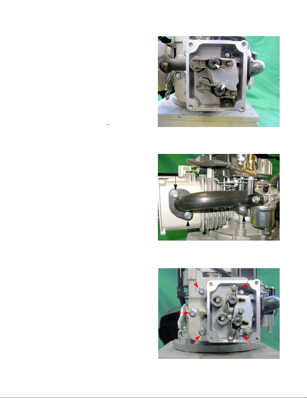
P71 Series Vertical Shaft Engines
Figure 9.3
Jam screws
Figure 9.4
Figure 9.5
6. Loosen the jam screws and fulcrum nuts that secure
the rocker arms using a 10mm wrench and a 14mm
wrench. See Figure 9.3.
7. Pivot the rocker arms aside, or remove them completely, and remove the push rods.
NOTE: Once broken-in, the rocker arm should be
kept with its corresponding valve.
NOTE: The intake and exhaust push rods are iden-
tical and interchangeable. It is preferable,
but not absolutely necessary to return the
same push rods to their original locations on
engine with substantial (>
ing time.
8. Remove the muffler and exhaust manifold, by following the steps described in Chapter 8: Exhaust.
100 hours) operat-
9. Remove the two screws that secure the intake manifold to the cylinder head. See Figure 9.4.
10. Loosen the nut on the intake manifold support stud.
11. Remove the cylinder head bolts using a 10mm
wrench. See Figure 9.5.
12. Lift the cylinder head off of the engine.
13. Carefully clean all sealing surfaces of all gasket residue. Do not scratch the sealing surfaces.
NOTE: Make a visual inspection of the valves and
cylinder bore to confirm the initial diagnosis.
14. Place a new head gasket on the cylinder or head,
82
depending which one has the alignment dowels.
Use the alignment dowels to hold it in place while
positioning the head on the cylinder.
Page 89

Cylinder head
Figure 9.6
15. Position the cylinder head on the engine block.
16. Install the 5 head bolts, and tighten them to a torque
of 221 - 239 in lb. (25 - 27 Nm) in 89 in lb (10 Nm)
steps. See Figure 9.6.
17. Insert the push rods.
18. Install the rocker arms. Adjust the valve lash by following the steps described in Chapter 1: Intr oductio n.
19. Install a new intake manifold gasket.
20. Install the intake manifold screws and tighten the
support stud nut.
21. Install the muffler by following the steps described in
Chapter 8: Exhaust.
22. Test run the engine in a safe area before returning it
to service. Check all safety features.
83
Page 90

P71 Series Vertical Shaft Engines
Figure 9.7
Figure 9.8
Intake
Exhaust
Valves
Valves and valve parts, like springs and keepers, are not available as service parts. The valves and valve seats
can be serviced by grinding and lapping or the hea d can be replace d. Depending on local m achine and labor cost s, it
is probably more economical to replace the cylinder head versus servicing the valves.
To service the valves:
NOTE: Servicing valves during the warranty period
will void the warranty . Warranty valve rep airs
are to be accomplished by replacing the cylinder head.
1. Remove the cylinder head by following the steps
described earlier in this chapter.
NOTE: Do not try to service the valve while the
head is still attached to the engine. Damage
to the cylinder head and/or piston can result
2. Remove the valve retainers by applying light finger
pressure on the valve retainers and sliding them forward. See Figure 9.7.
3. Lift the springs off of the valve stems.
4. Slide the valves out of the cylinder head.
NOTE: Only the intake valve has a va lve guide seal.
See Figure 9.8.
NOTE: Inspect the valves for signs of damage. If a
valve is damaged, replace the cylinder head.
84
Page 91

Cylinder head
Figure 9.9
Seat angle is 46
o
0.043-.050”
Figure 9.10
45
o
Inspect for a
burnt edge
5. Inspect the valve seat. See Figure 9.9.
• Valve seats are 46 degrees.
NOTE: This engine does not have the standard 3 angle
cut.
• Seat width should be 0.044” - 0.054” (1.13 - 1.38
mm).
NOTE: The valve seat can be ground to clean it up as long
as the finished seat is within the tolerances listed
above.
6. Inspect the valve stem. See Figure 9.10.
7. Inspect the valve springs.
NOTE: Valve spring free length should be 1.302” - 1.362”
(33.07 - 34.59 mm).
8. Install the valves in the cylinder head by following
steps 2 - 5 in reverse order.
9. Test the valves for leaks by:
9a. Place the cylinder head on a couple of wood
blocks with the valves facing up.
9b. Pour a small amount of gasoline or parts clean-
ing solvent into the combustion chamber (just
enough to cover the valves).
9c. Let the cylinder head sit for ten minutes.
9d. Check for gasoline leaking out of the intake and
exhaust ports.
10. Install the cylinder head by following the steps
described earlier in this chapter.
1 1. Set the valve lash by following the steps described in
Chapter 1: Introduction.
12. Test run the engine in a safe area before returning it
to service.
85
Page 92

P71 Series Vertical Shaft Engines
Figure 9.11
Jam screws
Figure 9.12
Push rod guide
Push rod guides
NOTE: The push rod guides are a wear item. On
extreme cases, the guides can wear to a
point that the push rods slip out from under
the rocker arms.
To remove/replace the push rod guides:
1. Disconnect and ground the spark plug high tension
lead.
2. Remove the engine shroud by following the procedures described in Chapter 6: Starters
3. Remove the spark plug using a 13/16” or 21mm
wrench.
4. Rotate the crankshaft until it is at TDC of the compression stroke by following the steps described in
the valve lash section of Chapter 1: Introduction.
5. Remove the four screws securing the valve cover
using a 10mm wrench.
6. Remove the rockers and fulcrum nuts using a 14
mm wrench and a 3 mm hex key. See Figure 9.11.
7. Remove the push rods.
8. Remove the rocker studs using a 12 wrench. See
Figure 9.12.
9. Remove the push rod guide.
10. Install the guide by following the previous steps in
reverse order.
NOTE: Tighten the rocker studs to a torque of 141 -
177 in lbs (16 - 20 Nm).
11. Adjust the valve lash by following the steps
described in Chapter 1: Introduction.
12. Test run the engine in a safe area before returning it
to service.
86
Page 93

Crankshaft, piston and connecting rod
Figure 10.1
Temperature Compensator
CHAPTER 10: CRANKSHAFT, PISTON AND CONNECTING ROD
There are a a few different paths that can be followed when disassembling an engine. This chapter will cover the
removal of components in one order, but it is written so that the technician can jump around to the component being
removed.
The first step to disassemble the engine is to remove the engine from the application by following the steps
described in the service manual for that particular application.
NOTE: The MTD engine is NOT to be opened unde r warr an ty. If an internal engine failure occurs during the
warranty period, replace the whole engine, no short blocks.
1. Drain and save the oil from the engine by following
the steps described in Chapter 1: Introduction.
2. Remove the air filter.
NOTE: Any fuel inside the carburetor’s float bowl
will drain into the air filter when the engine is
tipped.
3. Remove the engine from the apparatus by following
the procedures described in the apparatus’ service
manual.
4. Remove the screw that holds the compensator to
the cylinder using a 10 mm wrench. See Figure
10.1.
5. Slide the compensator rod out of the air vane.
6. Remove the two screws that hold the intake mani-
fold to the cylinder head using a 10 mm wrench. See Figure 10.1.
7. Remove the nut that holds the intake manifold to the support stud using a 10 mm wrench.
8. Remove the engine shroud by following the steps described in Chapter 6: Starter systems
NOTE: The shroud, fuel tank, carburetor and intake manifold are removed as one assembly.
9. Remove the starter by following the steps described in Chapter 6: Starter systems.
10. Remove the flywheel and ignition module by following the steps described in Chapter 7: Ignition system.
11. Remove the muffler by following the steps described in Chapter 8: Exhaust.
NOTE: At this point, it would be a good idea to service the PCV valve by following the steps described in
Chapter 5: Lubrication.
12. Remove the blade brake assembly, if equipped.
13. Remove the cylinder head by following the steps described in Chapter 9: Cylinder head.
14. Clean the cylinder bore and remove all carbon.
15. Turn the engine over.
87
Page 94

P71 Series Vertical Shaft Engines
Figure 10.2
Cam shaft
Compression
relief
Figure 10.3
Timing marks
Figure 10.4
Valve tappets
16. Remove the sump bolts using a 10mm wrench.
17. Carefully slide the sump off of the crank shaft. See
Figure 10.2.
18. Remove the camshaft. See Figure 10.3.
NOTE: Align the timing marks to allow easier
removal of the cam shaft and to help protect
the compression relief from damage.
NOTE: A paint pen can be used to fill in the timing
marks for better visibility.
19. Remove the valve tappets. See Figure 10.4.
NOTE: The valve tappets should be kept riding
against their original lobes. Once broken in,
switching the tappets to run on different cam
lobes will cause rapid tappet and cam wear.
Mark each tappet to identify which lobe it
was riding on.
88
Page 95

Crankshaft, piston and connecting rod
Figure 10.5
Remove the connecting rod bolts
Place a match mark
here
Figure 10.6
Connecting rod
Figure 10.7
Piston ring pliers
NOTE: Match mark the connecting rod cap and the con-
necting rod so that they can be reassembled in the
proper orientation.
20. Remove the connecting rod cap using a 7 mm
wrench. See Figure 10.5.
NOTE: Rotating the crank shaft after the connecting rod
bolts are removed will help to separate the connecting rod from the cap. See Figure 10.6.
21. Push the piston out of the cylinder.
22. Remove the piston rings from the piston using a pair
of piston ring pliers. See Figure 10.7.
89
Page 96
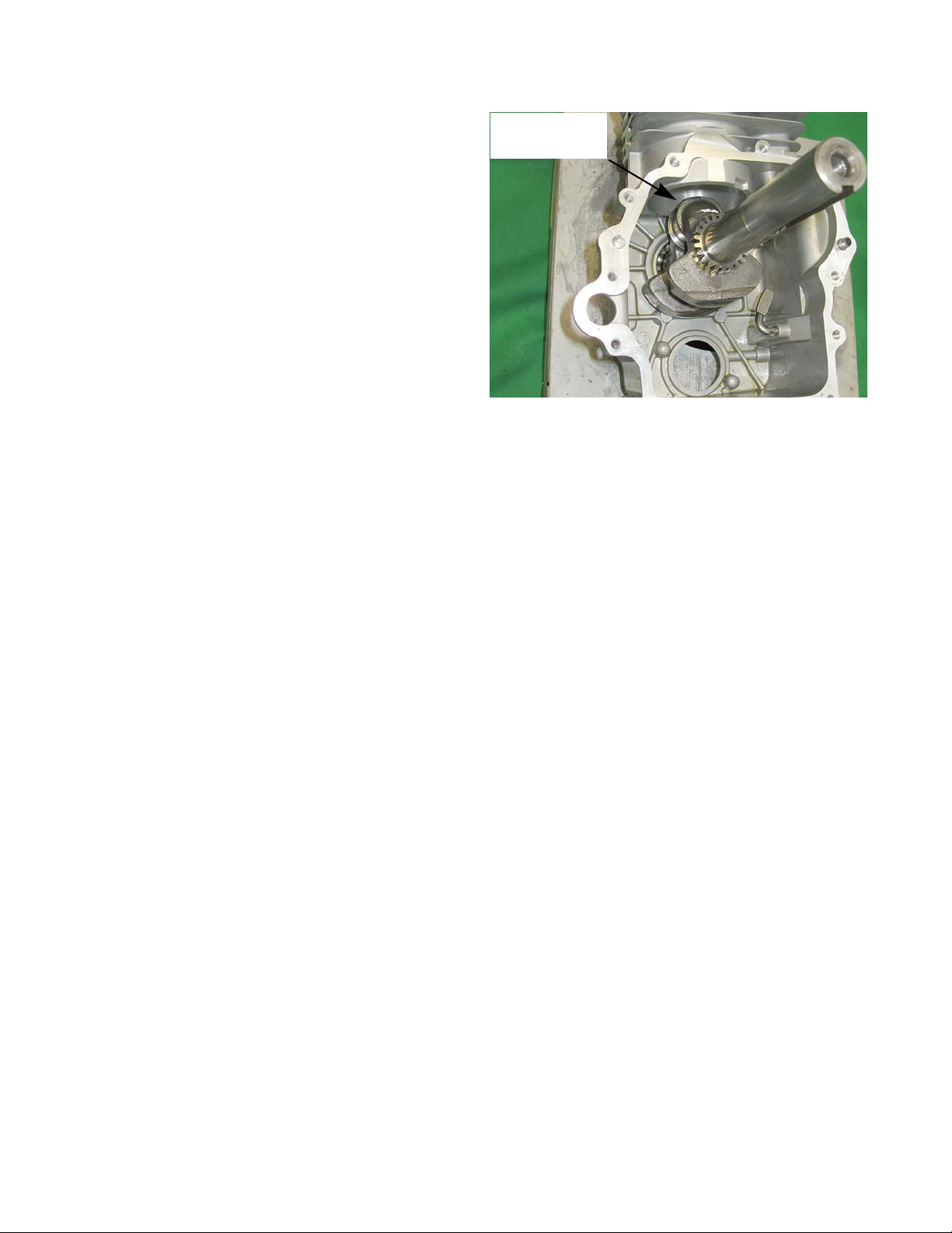
P71 Series Vertical Shaft Engines
Figure 10.8
Lift up on
crank shaft
23. Remove the crank shaft. See Figure 10.8.
90
Page 97
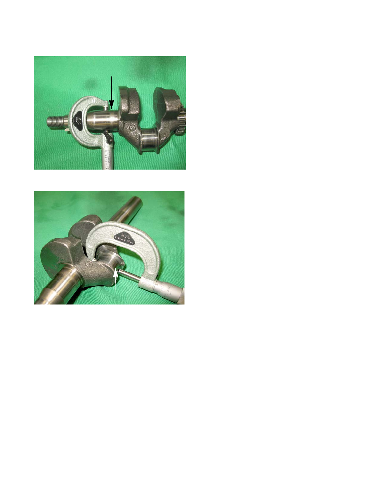
Crank shaft inspection
Figure 10.9
Bearing contact
area
Figure 10.10
Crank pin
Crankshaft, piston and connecting rod
1. Inspect the crank shaft journals for galling, scoring,
pitting or any other form of damage.
2. Measure the journals at the bearing contact points
using a vernier caliper or a micrometer. See Figure
10.9.
3. Inspect the crank pin for galling, scoring, pitting or
any other form of damage.
4. Measure the crank pin using a vernier caliper or a
micrometer. See Figure 10.10.
5. Check the crank shaft for straightness by measuring the run out. The crank shaft run out can be check by:
5a. Place the crank shaft on a pair of matched V-blocks or in the engine block with the sump installed.
5b. Place a dial indicator at a smooth point at either end of the crank shaft.
5c. Slowly turn the crank shaft while watching the dial indicator.
NOTE: Stop the crank shaft before the dial indicator hits the keyway.
5d. Compare the reading on the dial indicator to the specification listed at the end of this chapter.
5e. Repeat the above steps on the other end of the crank shaft.
91
Page 98
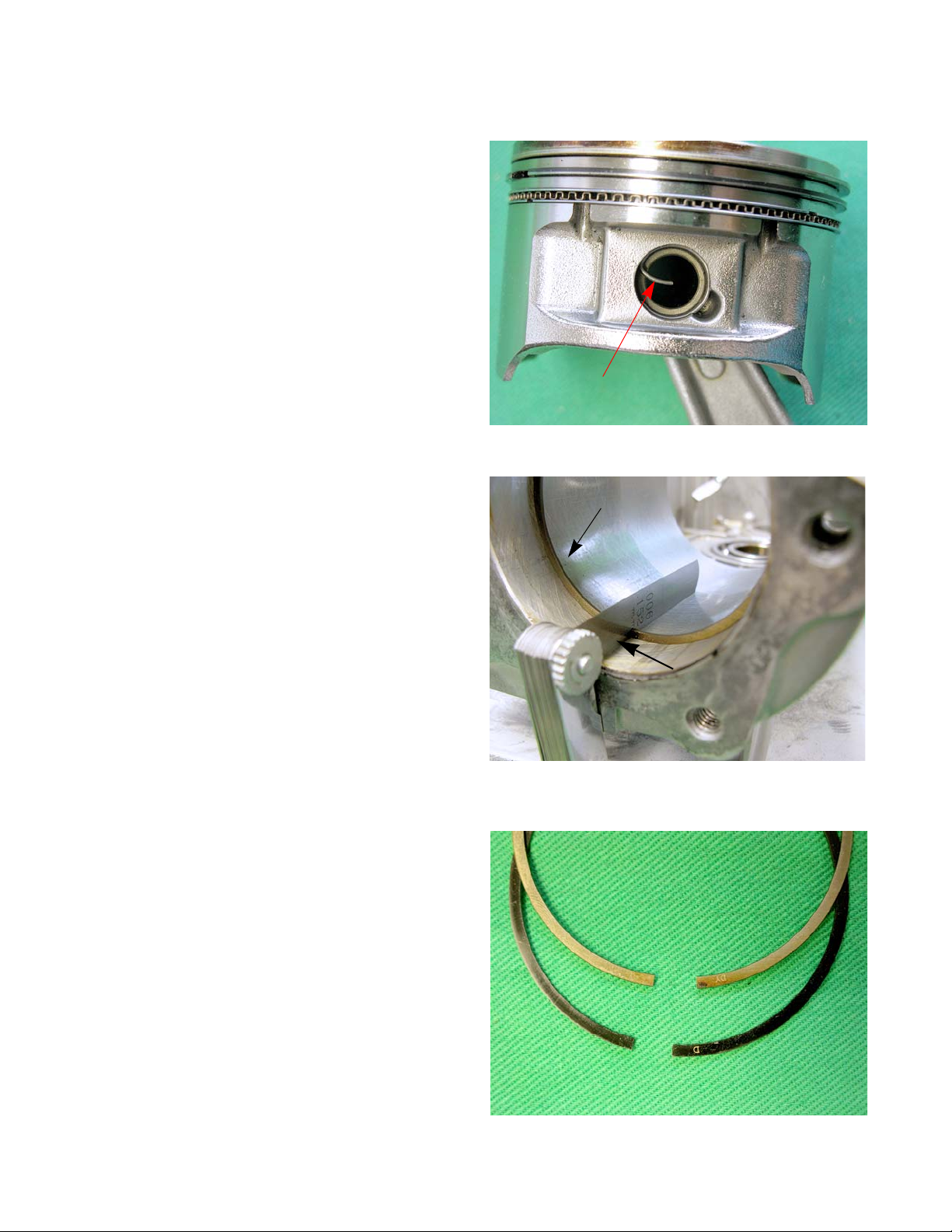
P71 Series Vertical Shaft Engines
Figure 10.11
Piston pin clip
Figure 10.12
Feeler gauge
Piston ring
Figure 10.13
Top ring
Middle ring
Piston Inspection
1. Separate the piston from the connecting rod:
1a. Remove one of the piston pin clips.
See Figure 10.11.
1b. Push the piston pin out of the piston.
1c. Slide the connecting rod out of the piston.
2. Clean the piston and remove all carbon from the
rings and ring groves.
3. Insert one ring into the cylinder. Push it down about
one inch from the top. See Figure 10.12.
4. Measure the end gap with a feeler gauge and compare to the chart at the end of this chapter.
See Figure 10.12.
5. Repeat steps 3 and 4 on the other rings.
6. Install rings back onto the piston.
NOTE: To help identify the top surface of the piston
rings, they have letter(s) etched on them.
See Figure 10.13.
92
Page 99
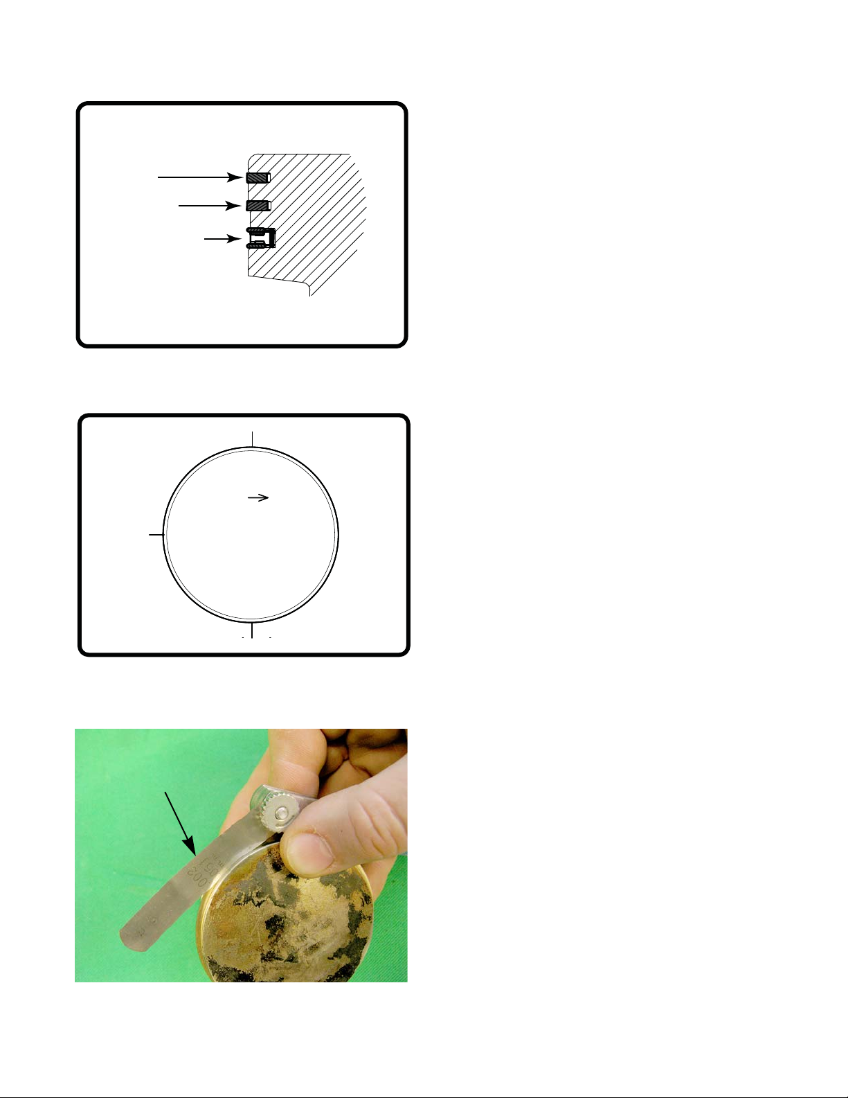
Crankshaft, piston and connecting rod
Top ring
Middle ring
3 piece oil ring
Figure 10.14
Figure 10.15
Oil ring
Middle
ring
Top ring
Piston ring end
gap stagger
Figure 10.16
Feeler gauge
NOTE: The top ring is symmetrical and the middle ring has
a tapered profile. The larger radius of the middle
ring should face the crankshaft. See Figure 10.14.
NOTE: The piston ring end gap s need to be stagge red 90
apart. See Figure 10.15.
7. Measure the distance between the ring and th e ring
land using a feeler gauge and compare the measurement to the chart at the end of this chapter.
See Figure 10.16.
o
93
Page 100

P71 Series Vertical Shaft Engines
Figure 10.17
Figure 10.18
Measure at right angles
Figure 10.19
8. Inspect the piston pin for galling, scoring, pitting or
any other form of damage.
9. Measure the piston pin using a vernier caliper or a
micrometer. See Figure 10.17.
Connecting rod inspection
1. Inspect the connecting rod for cracks or any signs of
damage.
2. Install the rod cap and tighten to a torque of 102 111 in-lbs (11.5-12.5 Nm)
3. Measure the inside diameter of both ends of the
connecting rod and compare the measurements to
those listed in the chart at the end of this chapter.
See Figure 10.18.
NOTE: Take two measurements 90 degrees apart.
This will check the out of roundness of the
connecting rod.
4. Take the crankshaft journal measurement and subtract it from the connecting rod measurement to get
the connecting rod to journal running clearance.
Compare that number to the one listed in the chart
at the end of this chapter.
5. Insert the small end of the connecting rod into the
piston so that the con rod cap bolt heads are poi nt ing in the opposite direction of the arrow on the piston crown. See Figure 10.19.
6. Insert the piston pin.
7. Insert the piston pin clip.
94
 Loading...