

Page 1

Service Manual
Commercial MMZ Rider
NOTE: These materials are for use by trained technicians who are experienced in the service and repair of outdoor power
equipment of the kind described in this publication, and are not intended for use by untrained or inexperienced individuals.
These materials are intended to provide supplemental information to assist the trained technician. Untrained or inexperienced individuals should seek the assistance of an experienced and trained professional. Read, understand, and follow
all instructions and use common sense when working on power equipment. This includes the contents of the product’s
Operators Manual, supplied with the equipment. No liability can be accepted for any inaccuracies or omission in this publication, although care has been taken to make it as complete and accurate as possible at the time of publication. However, due to the variety of outdoor power equipment and continuing product changes that occur over time, updates will be
made to these instructions from time to time. Therefore, it may be necessary to obtain the latest materials before servicing
or repairing a product. The company reserves the right to make changes at any time to this publication without prior notice
and without incurring an obligation to make such changes to previously published versions. Instructions, photographs and
illustrations used in this publication are for reference use only and may not depict actual model and component parts.
© Copyright 2005 MTD Products Inc. All Rights Reserved
MTD Products Inc - Product Training and Education Department
FORM NUMBER - 769-01760
3/2005
Page 2

Page 3

SECTION 1
Cub Cadet Commercial M60 Tank - 2002 and prior years
PTO Belt Removal ......................................................................................................1
Cutting Deck Removal ................................................................................................3
Cutting Deck Drive Belt Removal ...............................................................................5
Spindle Removal and Disassembly ............................................................................6
Hydrostatic Drive Belt Removal ..................................................................................7
Electric PTO Clutch Removal .....................................................................................9
Electric PTO Clutch Specifications ...........................................................................10
Hydrostatic Drive Assembly Removal ......................................................................11
Hydrostatic Pump / Transmission Removal .............................................................15
Left Transmission Disassembly and Inspection .......................................................18
Left Transmission Shimming and Assembly ........................................................22
Shimming Procedures ..............................................................................................24
Inner Housing ...........................................................................................................24
Outer Housing ..........................................................................................................24
Preparation ...............................................................................................................29
Lap Bar Adjustment ..................................................................................................29
Neutral Control Adjustment ......................................................................................29
Creep Adjustment .....................................................................................................30
Parking Brake Adjustment ........................................................................................33
Preliminary Setup .....................................................................................................35
Lift Adjustment Rods ................................................................................................35
Side to Side Adjustment ...........................................................................................35
Mower Deck Leveling ...............................................................................................35
Front to Back Adjustment .........................................................................................37
SECTION 2
Cub Cadet Commercial M60 Tank - 2003/4 Update
Changes for 03/04.......................................................................................................1
Drive System Adjustment ............................................................................................1
Testing Hydro Pump Output........................................................................................4
Replacing the Hydro Pump .........................................................................................6
Replacing the Hydro Motor........................................................................................10
Brake Linkage Adjustment ........................................................................................13
M72 Update...............................................................................................................16
Other Tank Features .................................................................................................19
1
Page 4

2
Page 5
Cub Cadet Commercial M60 Tank - 2002 and prior years
Service Manual
Cub Cadet Commercial M60 Tank - 2002 and prior years
PTO Belt Removal
1. Pivot the seat assembly forward.
2. Remove the lock nut and hex bolt securing the
negative battery cable to the negative battery terminal using a 7/16” socket and a 7/16” wrench.
3. Remove the sparkplug wires from the sparkplugs
on the engine.
4. Lower the cutting deck to the lowest position.
5. Grasp the floor panel assembly and raise it to the
fully open position.
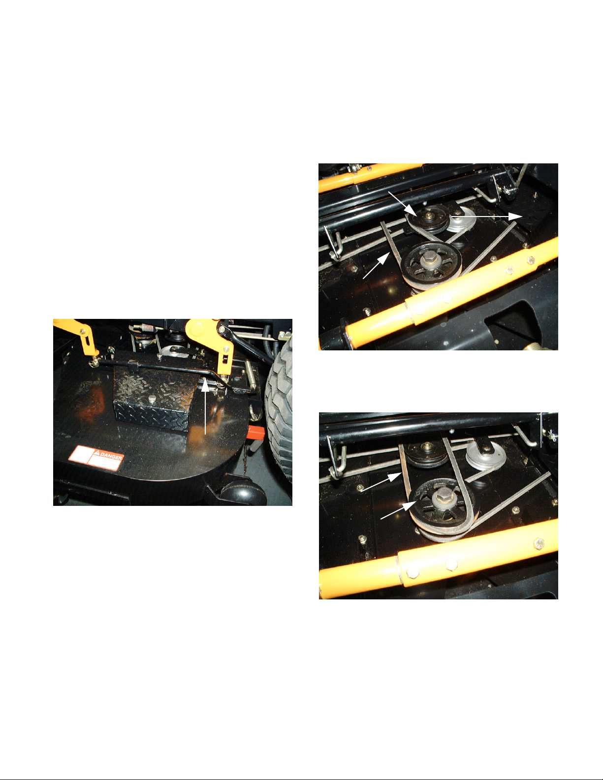
6. Unlatch the PTO belt release lever and slowly
pivot it away from the unit. See Figure 1.
7. Grasp the idler pulley and pull outward while rolling the PTO belt off. See Figure 2.
Idler Pulley
Pull Outward
PTO Belt
Figure 2
8. Roll the PTO belt off of the upper portion of the
double stack pulley. See Figure 3.
Release Lever
Figure 1
PTO Belt
Double Stack Pulley
Figure 3
1
Page 6
Cub Cadet Commercial M60 Tank - 2002 and prior years
9. Remove the PTO belt from the electric clutch pulley. See Figure 4.
PTO Belt
Electric Clutch Pulley
Figure 4
10. Inspect the V-belt for damage or wear.
11. Install the PTO belt in the reverse order above.
2
Page 7

Cub Cadet Commercial M60 Tank - 2002 and prior years
Cutting Deck Removal
NOTE: Prior to performing this section, the PTO
Belt Removal section must be performed.
1. Make certain the cutting deck is at the lowest
position. See Figure 1.
Deck Lift Handle
Clevis Pin
Hairpin
4. Pull the front mounting rod to the right several
inches until the left frame strut and lift brace are
free. See Figure 3.
Frame Strut
Above
To
Here
From
Here
Below
Lowest Position
Figure 1
2. Remove the hairpin and clevis pin from below
the deck lift handle, and install them above the
deck lift handle.
NOTE: This step must be performed to make
certain the deck lift handle is restrained and will
not spring back up during cutting deck removal.
3. Remove all six linch pins securing the cutting
deck to the deck link eye bolts and front mounting rod. See Figure 2.
Right
Front Mounting Rod
Lift Brace
Figure 3
5. Pull the front mounting rod to the left until the
right frame strut and lift brace are free.
6. Remove all four of the lift link eye bolts from the
deck lift pins. See Figure 4.
Eyebolt
Cutting
Deck
Eye Bolts
Figure 2
Deck Lift
Pins
Figure 4
7. Push the lift handle down (against the spring tension) and remove the hairpin and clevis pin from
above it.
8. Slowly raise the lift handle all the way up.
NOTE: The lift handle can swing up quickly if
care is not taken to hold it back.
3
Page 8
Cub Cadet Commercial M60 Tank - 2002 and prior years
9. Install the clevis pin and hairpin below the lift
handle.
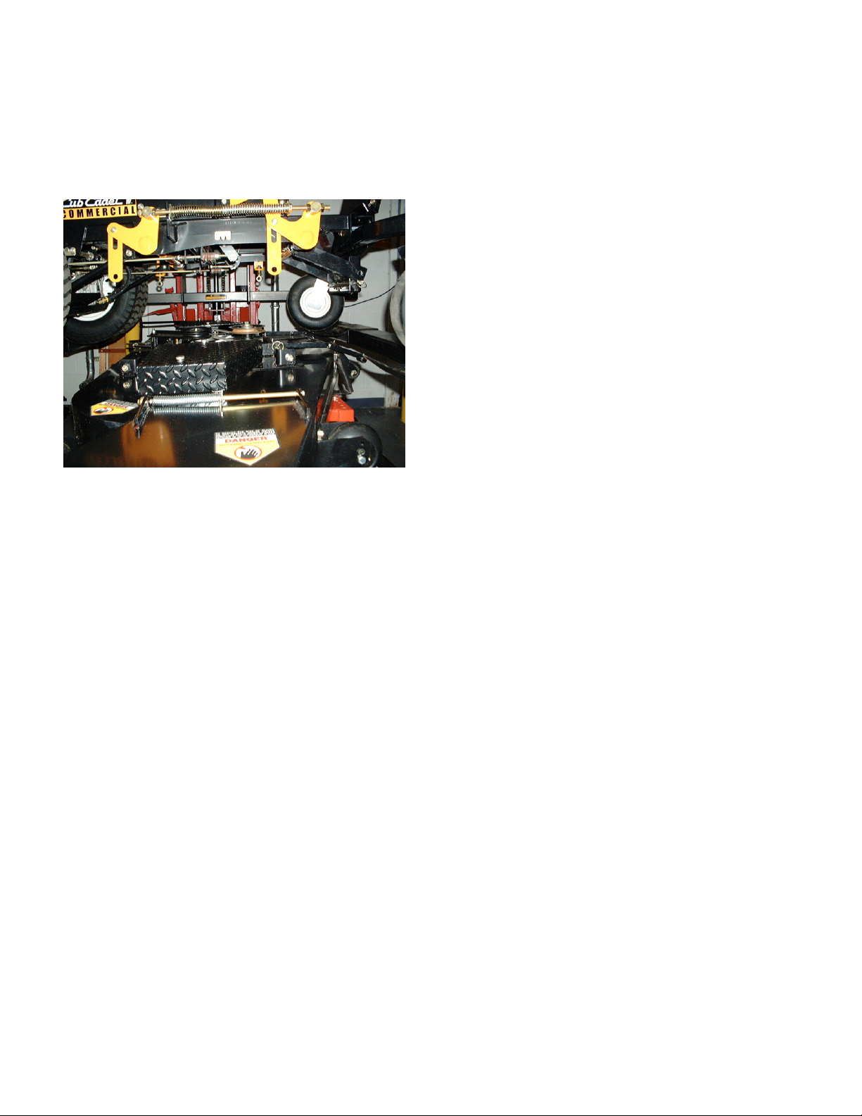
10. Slide the cutting deck assembly out from below
the unit. See Figure 5.
Cutting Deck
Figure 5
11. Install the cutting deck in the reverse order
above.
4
Page 9
Cub Cadet Commercial M60 Tank - 2002 and prior years
Cutting Deck Drive Belt Removal
NOTE: Prior to performing this section, the PTO
Belt Removal and Cutting Deck Removal sections must be performed.
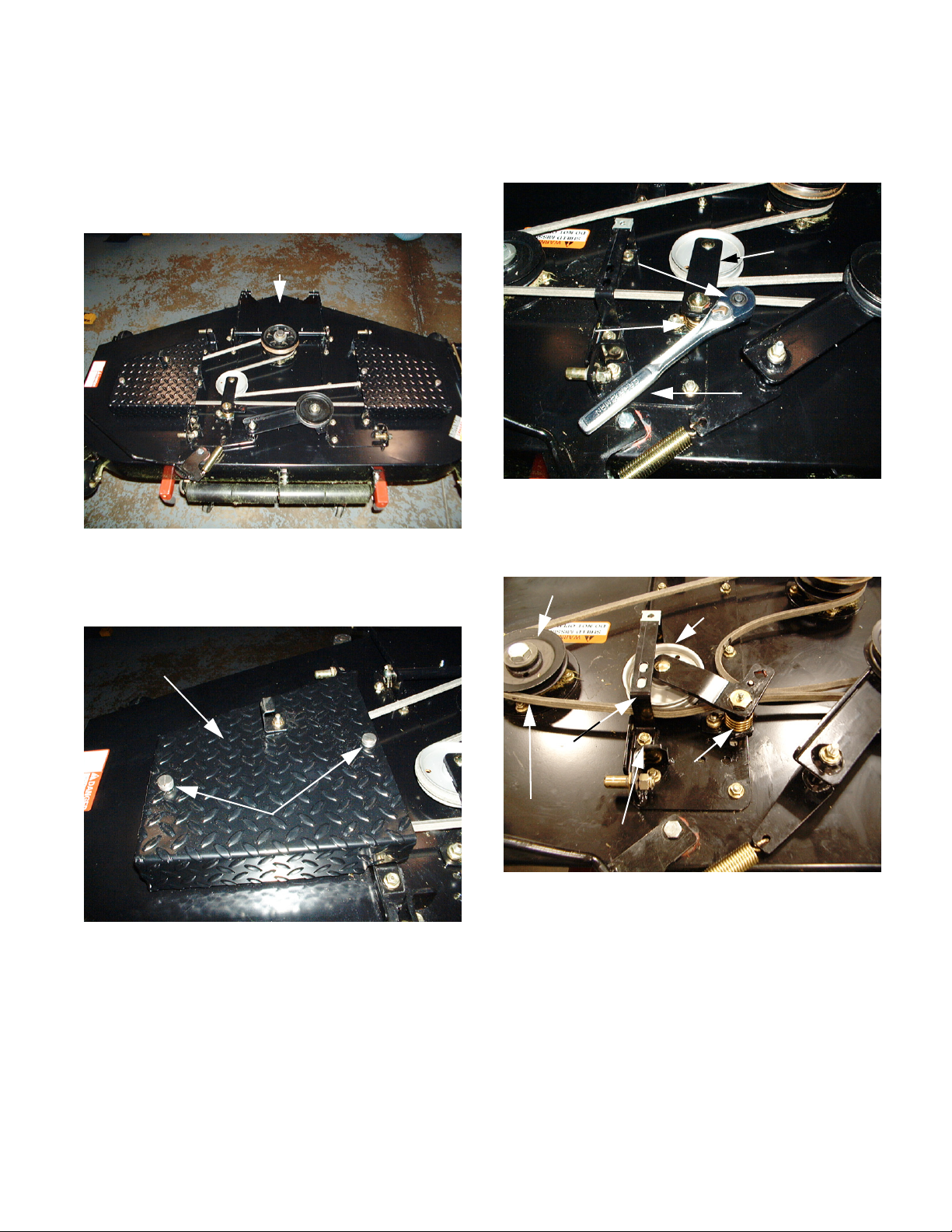
Cutting Deck
Figure 1
3. Release the spring tension being applied to the
deck drive belt by installing a 1/2" ratchet in the
square hole of the idler arm assembly and pulling
outward. See Figure 3.
1/2” Ratchet
in Square
Hole
Spring
Ten si on
Pull
Figure 3
4. Roll the deck drive belt off of the idler pulley. See
Figure 4.
Idler Arm
Assembly
1. Loosen both knobs securing each belt cover to
the deck assembly. See Figure 2.
Belt Cover
Knobs
Figure 2
2. Remove the belt covers.
Spindle Pulley
Idler Pulley
Spindle
Cover
Bracket
Deck Drive Belt
Lock Nut
5. Slowly retract the 1/2" ratchet and release the
compression spring tension.
6. Remove the deck drive belt from all three spindle
pulleys.
7. Remove both hex flange lock nuts securing the
left inner spindle cover bracket to the deck using
a 9/16” socket and a 9/16” wrench.
Compression
Spring
Figure 4
8. Inspect the deck drive belt for damage or wear.
9. Install the deck drive belt in the reverse order
above.
5
Page 10
Cub Cadet Commercial M60 Tank - 2002 and prior years
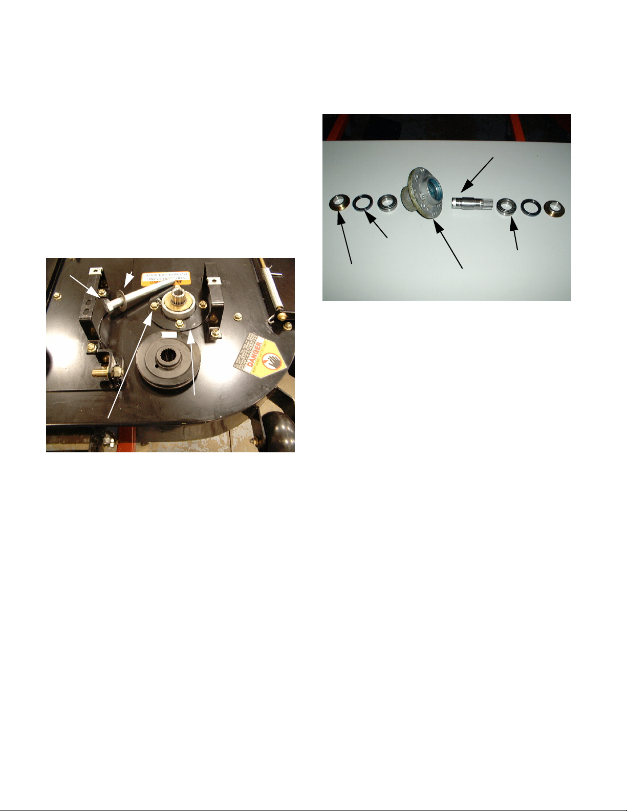
Spindle Removal and Disassembly
NOTE: Prior to performing this section, the Cut-
ting Deck Drive Belt Removal section must be
performed.
1. Remove the hex flange lock nut securing the
blade assembly together using a 1-1/8” socket
and a 1-1/8” wrench.
2. Remove the blade and spacer from the large hex
cap screw.
3. Remove the large hex cap screw and washer.
See Figure 1.
Large hex cap screw and washer
5. Press all of the spindle components apart and
inspect for wear or damage. See Figure 2.
Shaft Blade Spindle
Ring Seal
Cone Bearing
Oil Seal
NOTE: The bearings will be damaged by the
force of the press. New bearings should be
heated and set into position.
Spindle Housing
Figure 2
Spindle Housing
Spindle Hex Cap Screws and Lock Nuts
Figure 1
4. Remove all four hex cap screws and hex flange
lock nuts securing the spindle housing to the
deck assembly using a 9/16” socket and a 9/16”
wrench.
6. Assemble the spindle in the reverse order above.
6
Page 11
Cub Cadet Commercial M60 Tank - 2002 and prior years
Hydrostatic Drive Belt Removal
1. Pivot the seat assembly forward.
2. Remove the lock nut and hex bolt securing the
negative battery cable to the negative battery terminal using a 7/16” socket and a 7/16” wrench.
3. Remove the sparkplug wires from the sparkplugs
on the engine.
4. Remove the hex insert lock nuts and flat washers
from the input shafts of the right and left hydrostatic pump assemblies using a 3/4" socket. See
Figure 1.
Access Holes
Lock Nut
Input Shaft
Figure 1
Flat Washer
5. Remove the idler arm extension spring from the
left frame rail using vice grips. See Figure 2.
Idler Arm
Extension Spring
Frame Rail
Figure 2
NOTE: Make certain the orientation of the spring
is recorded.
6. Remove the extension spring from the idler arm
and set it aside.
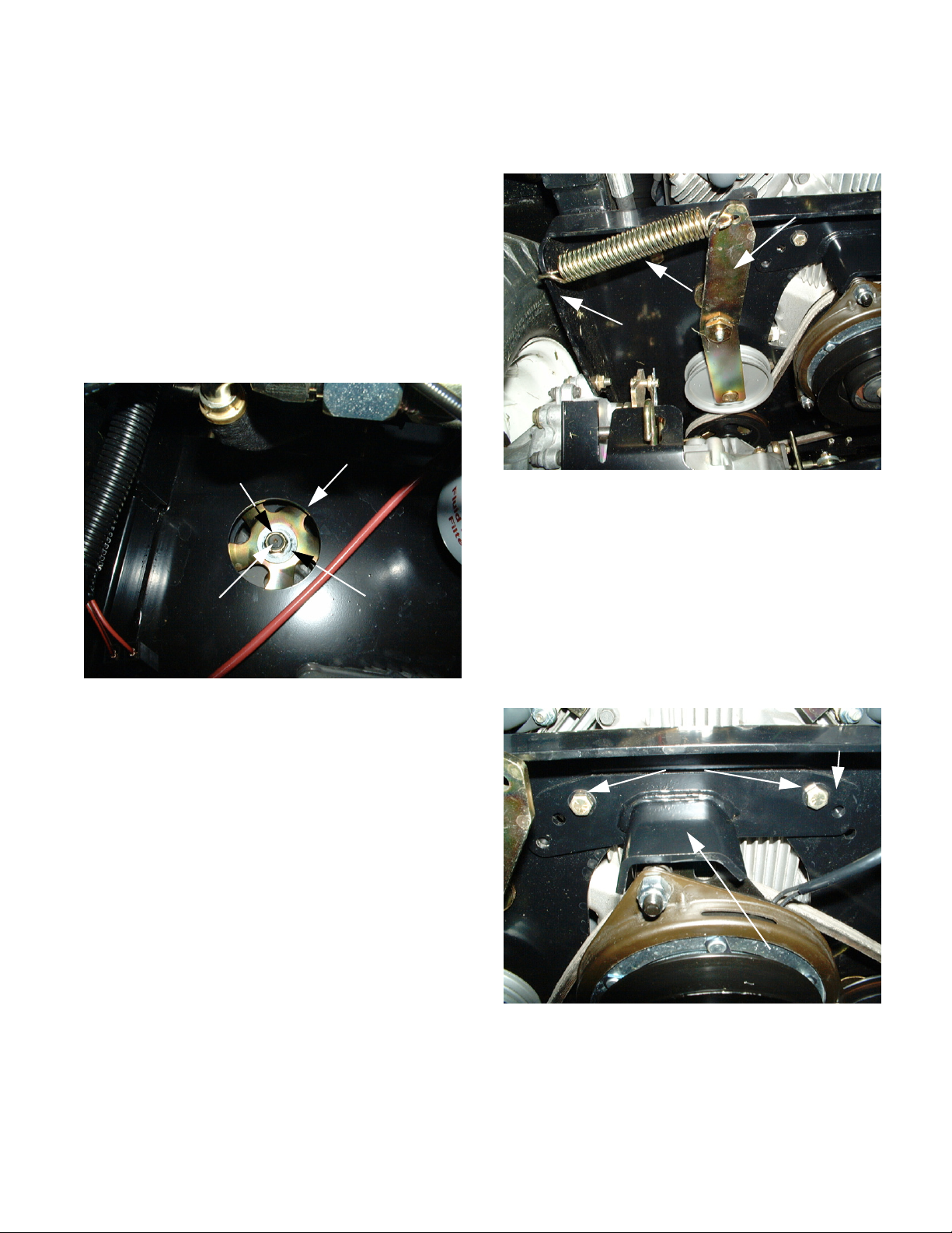
7. Remove both hex cap screws and flange lock
nuts securing the PTO clutch retension bracket
to the frame using a 1/2" socket and a 1/2"
wrench. See Figure 3.
NOTE: There are two 4” holes above each
hydrostatic pump assembly to access the lock
nuts.
PTO Bracket
Hex Cap Screws
Clutch Retension
Bracket
Figure 3
7
Page 12
Cub Cadet Commercial M60 Tank - 2002 and prior years
8. Disconnect the PTO clutch connector from the
wiring harness connector using a small flat-blade
screw driver. See Figure 4.
Wiring Harness
PTO Clutch Connector
Figure 4
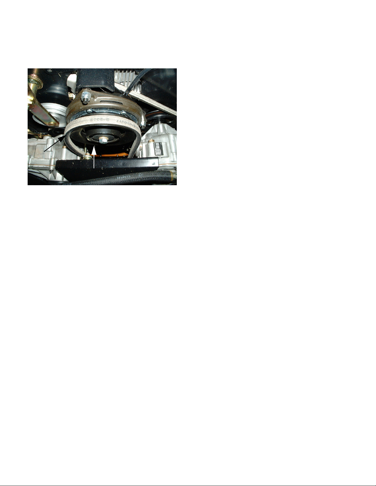
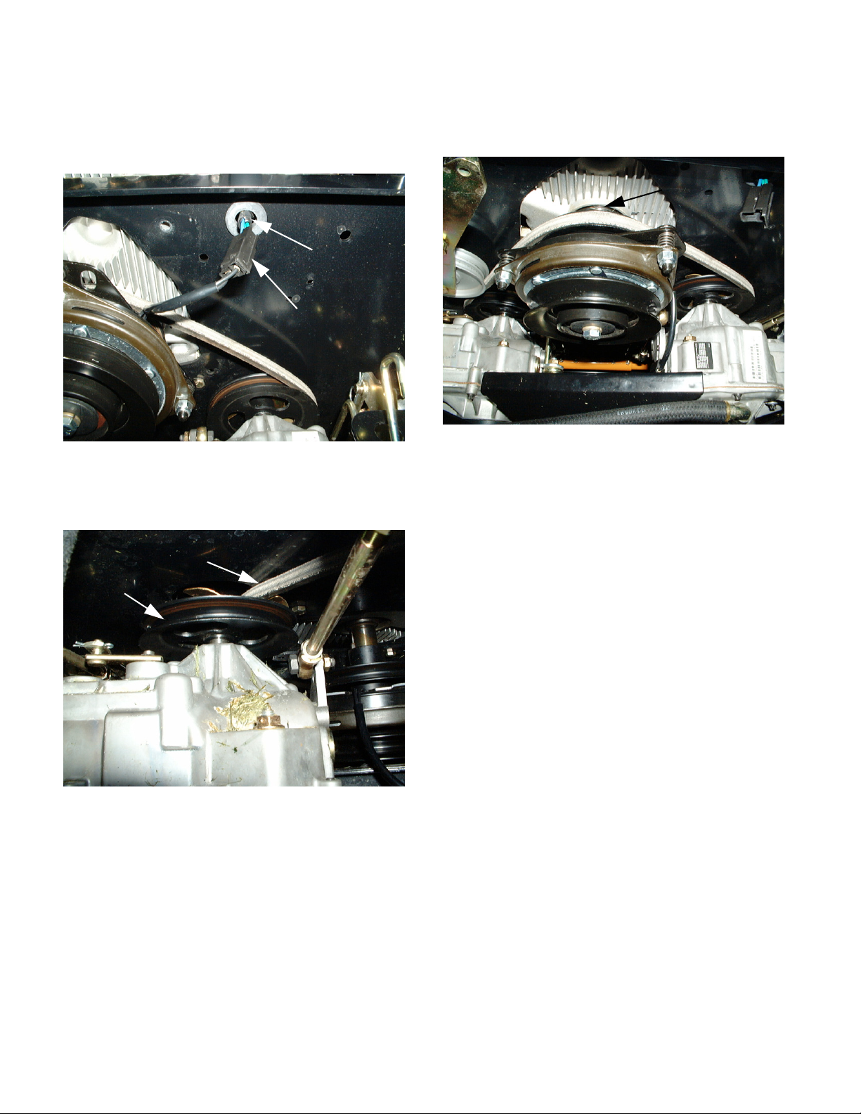
9. Roll the drive belt up and off of the right transmission pulley. See Figure 5.
12. Remove the drive belt from the engine drive pulley. See Figure 6.
Engine Drive
Pulley
Figure 6
13. Inspect the drive belt for damage or wear.
14. Install the hydrostatic drive belt in the reverse
order above.
Drive Belt
Transmission
Pulley
Figure 5
10. Push the drive belt up and over the right hydrostatic input shaft, hydro pulley fan and transmission pulley.
11. Push the drive belt up and over the left hydrostatic input shaft, hydro pulley fan and transmission pulley.
8
Page 13

Cub Cadet Commercial M60 Tank - 2002 and prior years
Electric PTO Clutch Removal
NOTE: Prior to performing this section, the
Hydrostatic Drive Belt Removal section must be
performed.
1. Remove the hex lock nut securing the negative
cable to the right front engine mounting bolt
using a 1/2" wrench. See Figure 1.
Lock Nut
Negative Cable
Figure 1
3. Loosen the front engine mounting bolts and hex
flange lock nuts securing the engine to the frame
using a 1/2" socket and a 1/2" wrench.
See Figure 3.
Engine Mounting Bolts
Figure 3
4. Remove the hex cap screw, lock washer and flat
washer securing the electric PTO clutch to the
engine crankshaft using a 5/8” socket.
See Figure 4.
2. Remove the hex lock nut securing the ground
wires to the left front engine mounting bolt using
a 1/2" wrench. See Figure 2.
Lock Nut
Ground Wires
Figure 2
Electric
PTO
Clutch
Flat Washer
Lock
Washer
Hex Cap Screw
Figure 4
9
Page 14

Cub Cadet Commercial M60 Tank - 2002 and prior years
5. Lift the rear of the engine slightly and remove the
electric PTO clutch from the engine crankshaft.
See Figure 5.
Electric PTO Clutch
Figure 5
6. Inspect and test the electric PTO clutch.
7. Install the electric PTO clutch in the reverse
order above.
Electric PTO Clutch Specifications
• Ogura part #520038
• Bore of 1-1/8", keyway for 1/4"x 1/4" square key
• Forged steel rotor
• E-coated metal parts
• Epoxy coated coil
• Sealed bearings with high temperature, long life
grease
• Static torque rating of 110 lb.-ft.
• Minimum "pull-in" voltage is 8 VDC
• Consumption of 50 watts (6 amps) at 12 VDC
• Coil resistance is 3 to 4 ohms at 70 F.
• Air gap (re-setting) between 0.013" (minimum)
and 0.015"
10
Page 15

Cub Cadet Commercial M60 Tank - 2002 and prior years
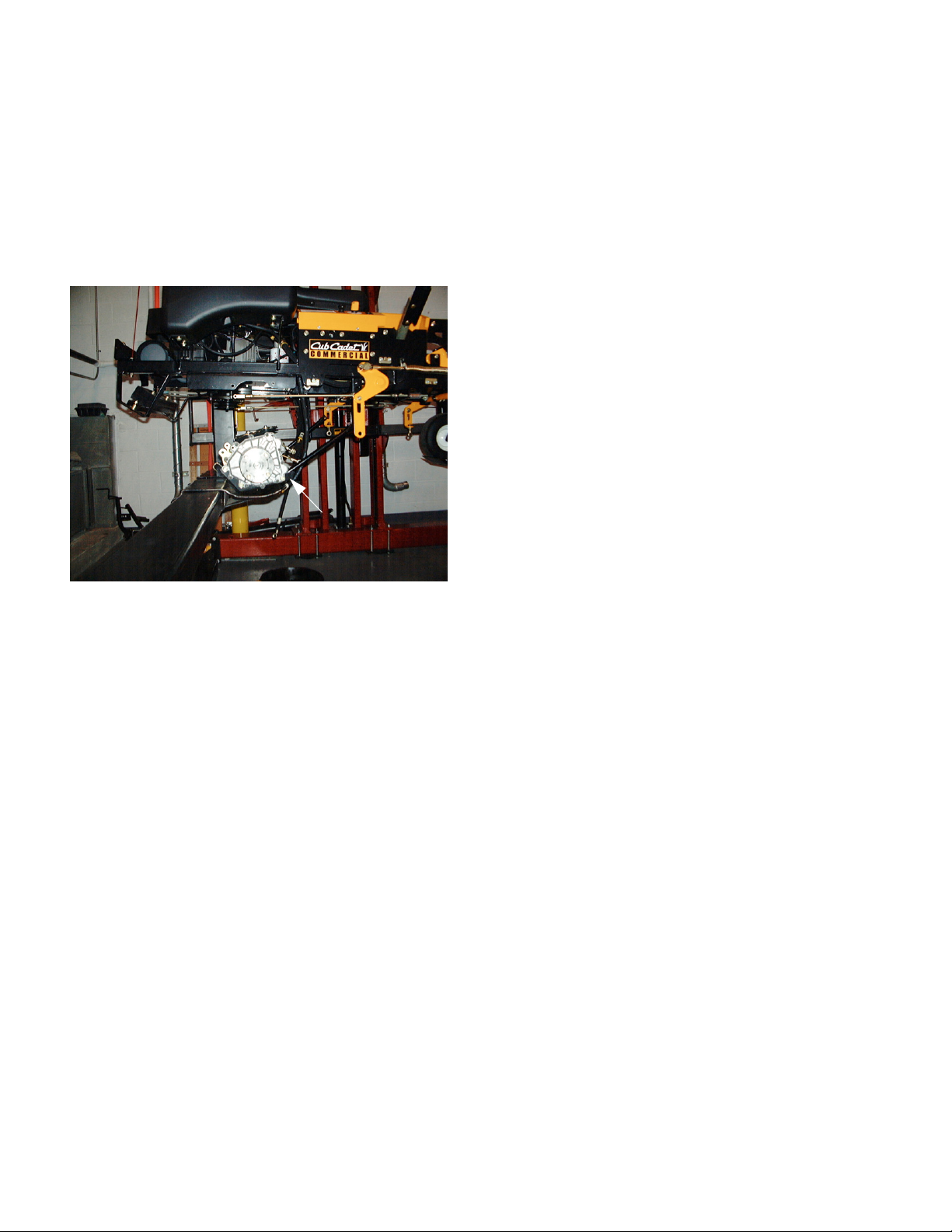
Hydrostatic Drive Assembly Removal
NOTE: The following section was performed with
a lift. Make certain the front castor wheels are
rotated rearward for maximum stability.
1. Pivot the seat assembly forward.
2. Remove the lock nut and hex bolt securing the
negative battery cable to the negative battery terminal using a 7/16” socket and a 7/16” wrench.
3. Remove the sparkplug wires from the sparkplugs
on the engine.
4. Place suitable hydrostatic fluid drain containers
under each hydrostatic pump and the hydrostatic
reservoir. See Figure 1.
6. Remove the drain caps from both hydrostatic
pumps, and the drain plug from the hydrostatic
reservoir using a 5/8” socket and an 11/16”
socket. See Figure 2.
Drain
Plug
Drain Caps
Figure 2
7. Allow all of the hydrostatic fluid to drain from the
system.
Hydrostatic Fluid
Drain Containers
Figure 1
5. Remove the fill cap from the hydrostatic reservoir.
8. Install all three oil drain plugs using a 5/8” socket
and an 11/16” socket.
9. Raise the rear of the unit until the rear wheels
are off the ground.
10. Remove all four lug nuts securing each rear tire
assembly using a 3/4" socket. See Figure 3.
11
Figure 3
Page 16
Cub Cadet Commercial M60 Tank - 2002 and prior years
11. Support the bottom of the skid plate assembly
from below.
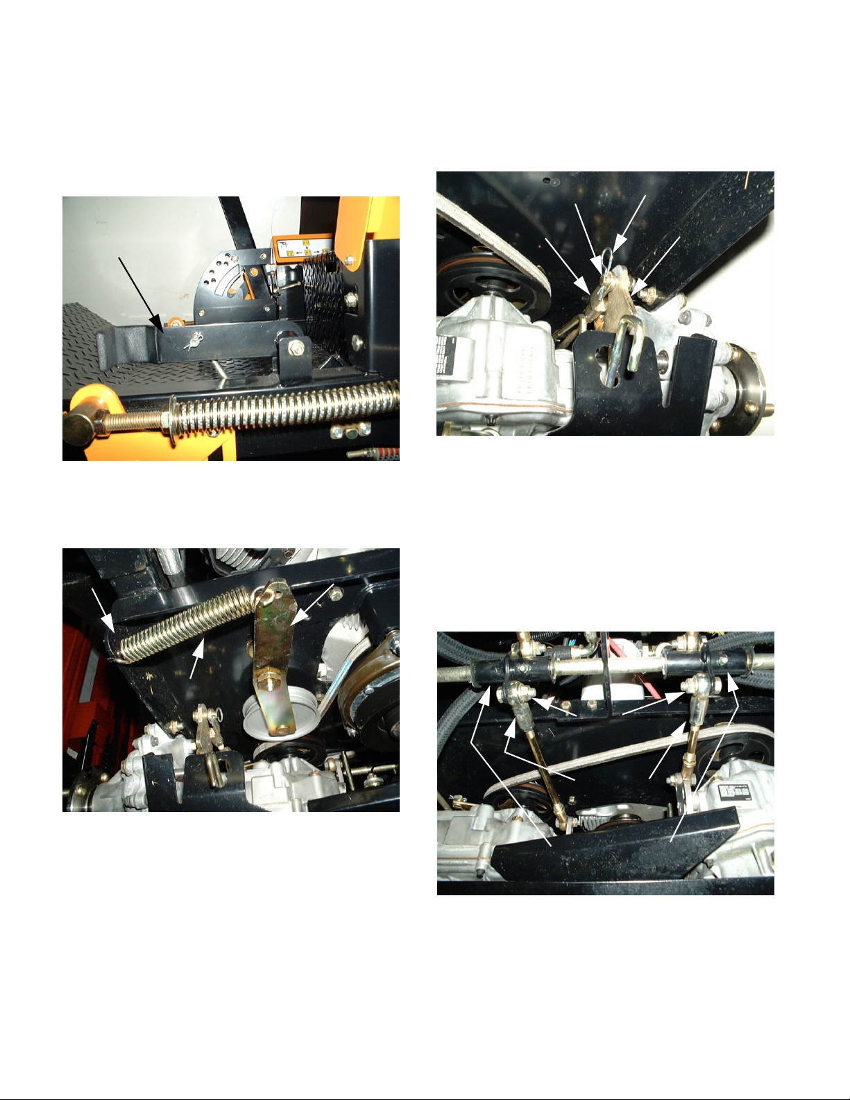
12. Make certain the parking brake is released. See
Figure 4.
Parking Brake
Figure 4
13. Remove the idler arm extension spring from the
left frame rail using vice grips. See Figure 5.
15. Remove both hairpins and clevis pins securing
the brake rod yokes to the brake actuation arms.
See Figure 6.
Clevis Pin
Brake Rod
Yoke
Figure 6
16. Engage the parking brake lever.
NOTE: The brake rod yokes will be pulled
forward and out of the way.
Hairpin
Brake Actuation
Arm
Left Frame Rail
Extension Spring
Figure 5
NOTE: Make certain the orientation of the spring
is recorded.
14. Remove the extension spring from the idler arm
and set it aside.
Idler Arm
17. Remove the hex flange lock nuts and shouldered
hex screws securing both connecting rod ball
joints to the center belle crank assemblies using
a 9/16” socket and a 9/16” wrench. See Figure 7.
Flanged Lock Nuts
and Hex Screws
Ball Joints
Center Bell Crank
Assemblies
Figure 7
12
Page 17

Cub Cadet Commercial M60 Tank - 2002 and prior years
18. Remove the hairpin and clevis pin from below
the deck lift lever.
19. Push the deck lift lever down as far as it will go
and place the clevis pin and hairpin above it. See
Figure 8.
Hairpin
Clevis Pin
Lift Lever
Figure 8
21. Remove both of the hex bolts, flat washers and
lock nuts securing the right and left hydrostatic
pumps to the frame using a 9/16” socket and a
9/16” wrench. See Figure 10.
Hex Bolts
and
Flat Washers
Skid Plate
Figure 10
22. Lower the skid plate assembly slightly.
NOTE: This keeps the deck links down.
20. Remove both hex lock nuts and carriage bolts
securing the skid plate frame struts to the mid
frame of the unit using a 9/16” socket.
See Figure 9.
Hex Lock Nuts and
Carriage Bolts
Frame
Struts
Deck Links Down
Figure 9
23. Remove the drive belt from both of the hydrostatic transmission pulleys.
24. Pull the drive belt rearward and out of the way.
NOTE: The drive belt is still secured around the
electric clutch.
25. Mark and record all of the hydrostatic line connections to the hydrostatic pumps.
See Figure 11.
Hydrostatic Lines
Hydrostatic Pumps
13
Figure 11
Page 18
Cub Cadet Commercial M60 Tank - 2002 and prior years
26. Make certain the hydrostatic fluid drain containers are below the skid plate assembly.
27. Remove all four of the hydraulic line connectors
from both hydrostatic pumps using a 3/4" wrench
and a 7/8” wrench.
28. Slowly lower the skid plate assembly and remove
it from the unit. See Figure 12.
Skid Plate
Assembly
Figure 12
29. Install the hydrostatic drive assembly in the
reverse order above.
14
Page 19
Cub Cadet Commercial M60 Tank - 2002 and prior years
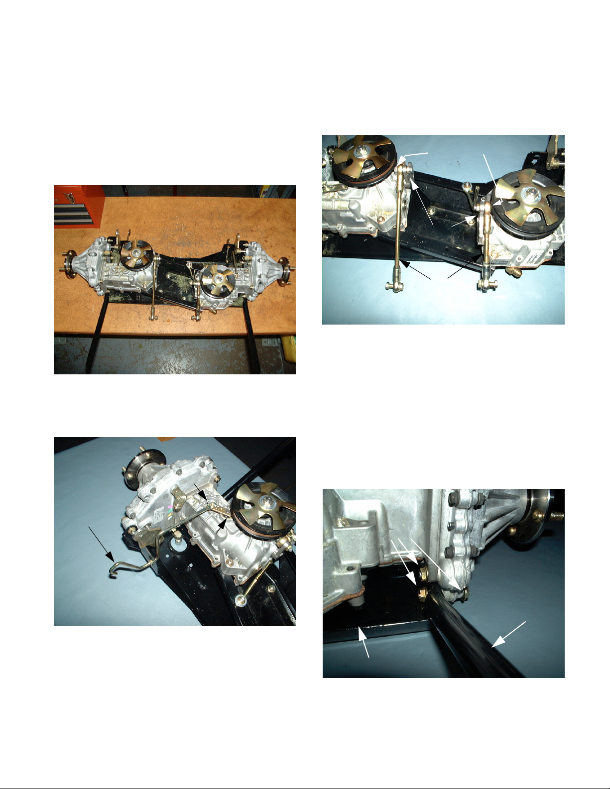
Hydrostatic Pump / Transmission Removal
NOTE: The following section has been written for
training and includes multiple steps for both the
left and right hydrostatic pump / transmission
assemblies. Prior to performing this section, the
Hydrostatic Drive Assembly Removal section
must be performed.
.
3. Remove both hex bolts and flange lock nuts
securing the short connecting rods to the neutral
return plates using a 1/2" socket and a 9/16”
wrench. See Figure 3.
Hex Bolts and
Lock Nuts
Neutral Return
Plates
Connecting
Rods
Figure 3
4. Remove both short connecting rods and set
them aside.
Figure 1
1. Remove both hairpins securing the pump
release rods to the bypass valves. See Figure 2.
Hairpin
Pump Release
Rod
Bypass
Valve
Figure 2
2. Remove both pump release rods.
NOTE: Record the orientation of the connecting
rods to the neutral return plates on both hydrostatic transmissions.
5. Remove the hex cap screw, flat washer and hex
flange lock nut that secure each frame strut to
the skid plate assembly using a 9/16” socket and
a 9/16” wrench. See Figure 4.
Hex Cap Screws,
Flat Washers, and
Hex Flange Lock Nuts
Frame Strut
Skid Plate
15
Figure 4
Page 20
Cub Cadet Commercial M60 Tank - 2002 and prior years
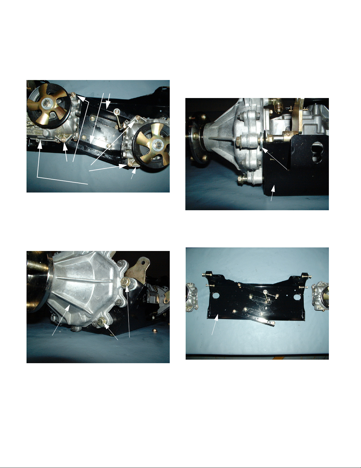
6. Remove all four hex cap screws and flange lock
nuts that secure the hydrostatic pump assemblies to the center pump support brackets using a
1/2" socket and a 1/2" wrench. See Figure 5.
Center Pump Support
Brackets
Hex Cap Screws
and Lock Nuts
Hydrostatic Pump Assembly
NOTE: The thick flat washers are used to make
up the difference between the hydrostatic pump
assembly housings and the skid plate assembly,
at the upper rear mounting hole (closest to the
dump valve lockout holes). See Figure 7.
Thick Flat
Washers
Figure 5
7. Remove all four remaining hex cap screws, flat
washers and flange lock nuts securing the hydrostatic pump assemblies to the skid plate assembly using a 1/2" socket and a 1/2" wrench. See
Figure 6.
Hydrostatic
Pump
Hex Cap Screws,
Flat Washers, and
Lock Nuts
Figure 6
Skid Plate
Figure 7
8. Remove both hydrostatic pump assemblies from
the skid plate assembly. See Figure 8.
Skid Plate
Figure 8
9. Assemble the hydrostatic pump/transmission
assembly in the reverse order above.
16
Page 21

Cub Cadet Commercial M60 Tank - 2002 and prior years
NOTE: When assembling the transmissions to
the skid plate assembly, tighten and then torque
the bolts in numerical succession. (outside to
inside) See Figure 9.
14/15
1
2
91011
6
5
12
13
Figure 9
16/17
8
7
4
3
Bolt Torque Specifications:
Part# Bolt # Size Description Torque
00002528 1-4 3/8-16 x
Mounts transmission motor to skid plate 33 ft. lbs.
2.00 Gr 5
00013198 5-8 5/16-18 x
Mounts transmission pump to brackets 19 ft. lbs.
2.00 Gr 5
01000372 9-12 3/8-16 x
.750 Gr 5
01005852 13 5/16-18 x
1.00 Gr 5
Mounts bracket to skid plate 33 ft. lbs.
Mounts belt guide to bracket 19 ft. lbs.
Strut bolts 33 ft. lbs.
Pump to final drive 22 ft. lbs.
17
Page 22

Cub Cadet Commercial M60 Tank - 2002 and prior years
Left Transmission Disassembly and
Inspection
Figure 1
1. Remove the hex insert lock nut and flat washer
securing the hydrostatic fan and pulley to the
hydrostatic input shaft using a 3/4" socket. See
Figure 2.
3. Remove all four hex flange lock nuts securing the
hydrostatic pump assembly to the transmission
assembly using a 1/2" socket and a 1/2" wrench.
See Figure 3.
Transmission
Hydrostatic
Pump
Hex Flange
Lock Nuts
Figure 3
NOTE: Use Loctite 271 during assembly.
4. Slowly separate the hydrostatic pump assembly
from the transmission assembly. See Figure 4.
Hex Insert Lock Nut
Fan
Pulley
Figure 2
NOTE: This step is not necessary if the hydro-
static pump assembly is not in question.
2. Remove the hydrostatic fan and pulley from the
input shaft.
NOTE: The fan blades point down.
Orientation of fittings
“O” Ring
14 Tooth
Hydrostatic
Pump
NOTE: Make certain the 14T spur gear on the
output shaft of the hydrostatic pump assembly
does not fall into the transmission assembly.
5. Remove and replace the large O-ring on the mating face of the transmission assembly.
Spur Gear
Transmission
Figure 4
18
Page 23

Cub Cadet Commercial M60 Tank - 2002 and prior years
6. Set the hydrostatic pump assembly aside.
7. Record the orientation of both hydraulic elbow fittings on the transmission assembly.
8. Remove both hydraulic fittings from the transmission assembly using an 11/16” wrench. See
Figure 5.
O Rings
Figure 5
9. Inspect and replace the O-ring on each fitting.
10. Remove the roll pin securing the brake actuation
arm to the brake shaft using a 5/32” punch. See
Figure 6.
11. Drive both centering roll pins into the inner case
halve using a punch. See Figure 7.
Inner Case
Half
Centering Roll
Pins
Perimeter Hex
Flange Lock nuts
and Hex Screws
Figure 7
12. Rotate the transmission assembly 90 degrees
and set it on the drive hub studs.
13. Remove all ten perimeter hex flange lock nuts
and hex washer head screws securing both case
halves to one another using a 3/8” socket and a
7/16” wrench.
14. Separate the case halves from one another
using a scraper. See Figure 8.
Brake Shaft
Brake Actuation
Arm
Roll Pin
Figure 6
Needle Bearing
Inner Housing Assembly
19
Case Halves
Figure 8
Page 24

Cub Cadet Commercial M60 Tank - 2002 and prior years
15. Remove the inner housing assembly.
16. Inspect the needle bearing in the inner housing.
NOTE: Remove and press in a new bearing if
needed.
17. Remove all of the shim washers from the top of
the reduction gear. See Figure 9.
Shim
Reduction Gear
Figure 9
Washers
19. Remove the brake assembly and inspect all of
the components. See Figure 11.
Brake Retaining
Dowel
Pins
Brake Shoe
Spring
Figure 11
NOTE: The brake shoe spring is slightly bent.
Make certain it is not distorted.
20. Inspect the brake retaining dowel pins.
See Figure 12.
Brake Shoes
Brake Shaft
18. Remove the reduction gear and inspect the
center needle bearing. See Figure 10.
Needle Bearing
Reduction Gear
Figure 10
Brake
Pins
Output Carrier
46T Ring Gear
Figure 12
21. Remove the 46T ring gear.
22. Remove all three 13T spur gears.
23. Remove the output carrier assembly.
13T Spur Gear
Assembly
20
Page 25

Cub Cadet Commercial M60 Tank - 2002 and prior years
24. Remove the center snap ring securing the axle
assembly in position using snap ring pliers. See
Figure 13.
Center Snap Ring
Axle Assembly
25. Press the axle assembly out of the outer ball
bearing. See Figure 14.
Internal Snap Ring
Ball Bearing
Figure 13
28. Inspect the outer oil seal and replace it if damaged or worn. See Figure 15.
Oil Seal
Figure 15
29. Inspect all components of the transmission
assembly.
30. Clean the mating surfaces of both halves of the
housing assembly and prepare them for assembly.
Axle Assembly
Snap Rings
Figure 14
26. Remove the internal snap ring securing the outer
ball bearing into the outer axle housing using
snap ring pliers.
27. Push the outer ball bearing out of the housing.
NOTE: The outer ball bearing can be damaged
by the press and should be replaced.
Ball Bearing
21
Page 26

Cub Cadet Commercial M60 Tank - 2002 and prior years
Left Transmission Shimming and
Assembly
1. Make certain both transmission mating faces are
clean.
2. If the outer oil seal was removed, press a new
one into the outer axle housing until it bottoms
out. See Figure 1.
Oil Seal
Outer Axle Housing
6. Secure the axle assembly in position with the
center snap ring using snap ring pliers.
7. Install the output carrier assembly, all three 13T
spur gears and the 46T ring gear onto the axle
assembly. See Figure 3.
Output Carrier
13T
46T Ring Gear
Figure 3
Spur Gear
Figure 1
3. Push the outer ball bearing into the outer axle
housing until it is firmly in position. See Figure 2.
Ball Bearing
Axle Assembly
Outer Axle Housing
Figure 2
4. Secure the outer ball bearing in position with the
large internal snap ring using snap ring pliers.
Large Internal
Snap Ring
Center Snap
Ring
8. Install the brake assembly. See Figure 4.
Brake Assembly
Figure 4
NOTE: Make certain the bend in the brake shoe
spring is flush up against the brake shaft.
5. Press the axle assembly into the outer ball bearing.
22
Page 27

Cub Cadet Commercial M60 Tank - 2002 and prior years
9. Install the reduction gear onto the axle assembly.
See Figure 5.
Axle Assembly
Figure 5
10. Make certain all of the gears turn smoothly without binding. See Figure 6.
Reduction
Gear
Figure 6
23
Page 28

Cub Cadet Commercial M60 Tank - 2002 and prior years
Shimming Procedures
NOTE: This section requires a measuring device
that can measure depth in thousands of an inch.
A dial caliper was used to perform this section.
Inner Housing
11. Locate a flat section of bar-stock and measure its
depth. This is bar-stock (1). See Figure 7.
A
Bar Stock (1)
14. Measure the distance from the top of bar-stock
(1) to the top of the center needle bearing boss.
15. Record the measurement._____ This is measurement (B).
16. Subtract measurement (B) from measurement
(A).
17. Record this measurement._____ This is measurement (C).
NOTE: Measurement (C) is the distance from the
mating surface of the inner housing to the top of
the center needle bearing boss.
NOTE: Example formula is ( A - B ) = C
Outer Housing
Locate two additional sections of bar-stock that are
identical in depth. These are bar-stocks (2) and (3)
18. Place both sections of identical bar-stock (2) and
(3) across the full width of the axle housing mating face.
19. Set bar-stock (1) across and on top of bar-stock
(2) and (3).
Figure 7
12. Record the measurement._____ This is measurement (A).
13. Place bar-stock (1) across the full width of the
inner housing mating face, next to the center
needle bearing boss. See Figure 8.
Bar Stock (1)
(B)
(A)
Inner Housing
Center Needle
Bearing Boss
20. Measure the distance from the top of bar-stock
(1) to the first shoulder of the axle shaft assembly. See Figure 9.
1
k
c
o
t
S
r
a
(D)
2
Bar Stocks 2 and 3
Figure 9
21. Record the measurement._____ This is measurement (D).
B
First shoulder of
the axle shaft
3
Figure 8
24
Page 29

Cub Cadet Commercial M60 Tank - 2002 and prior years
22. Measure the total distance of bar-stocks (1) and
(2). See Figure 10.
Bar Stock 1
(E)
Figure 10
23. Record the measurement._____ This is measurement (E).
24. Subtract measurement (E) from measurement
(D). See Figure 11 and 12.
Bar Stock 2
(D)
Figure 12
25. Record this measurement._____ This is measurement (F).
NOTE: Measurement (F) is the distance from the
mating surface of the outer axle housing to the
first shoulder of the axle shaft. This measurement should be greater than measurement (C).
NOTE: Example formula is ( D - E ) = F
26. Subtract measurement (C) from measurement
(F).
27. Record this measurement._____ This is measurement (Z).
(E)
Figure 11
NOTE: Example formula is ( F - C ) = Z
25
Page 30

Cub Cadet Commercial M60 Tank - 2002 and prior years
28. Shim the first shoulder of the axle assembly to
achieve a 5 to 20 thousands measurement of
(Z). See Figure 13.
NOTE: Z = 5 to 20 thousands.
Shim
Figure 13
NOTE: A 5 to 20 thousands measurement will
allow the unit to operated smoothly, without binding.
30. Place a bead of sealant around the outer
perimeter of the mating surface.
NOTE: Use Loctite 5999 or equivalent.
31. Set the inner housing on top of the outer axle
housing and align the centering roll pins by tapping them into place using a punch and a small
hammer.
32. Secure the inner housing to the outer axle housing with the ten hex washer head screws and hex
flange nuts removed earlier using a 3/8” socket
and a 7/16” wrench.
33. Make certain the centering roll pins are correctly
set in place.
34. Place the brake actuation arm onto the brake
shaft and drive the roll pin into place using a
5/32” punch. See Figure 15.
Brake Shaft
29. Drive the centering roll pins up using a punch.
See Figure 14.
Hex Washer
Head Screws
Inner Housing
Figure 14
Centering Roll
Pins
Brake Actuation
Arm
Roll Pin
Figure 15
26
Page 31

Cub Cadet Commercial M60 Tank - 2002 and prior years
35. Install both hydraulic elbow fittings to the correct
position using an 11/16” wrench. See Figure 16.
Loctite
Mounting
O Ring
14T Spur Gear
NOTE: Make certain the O-rings do not get damaged during installation.
36. Set the large O-ring onto the hydrostatic pump
assembly.
Hydraulic Elbow Fittings
Figure 16
Studs
40. Place the hydrostatic pulley and fan onto the
input shaft.
41. Secure the hydrostatic pulley and fan to the input
shaft with a flat washer and hex insert lock nut
using a 3/4" socket. See Figure 18.
Input Shaft
Flat Washer and
Hex Insert Lock Nut
Fan
Pulley
Figure 18
37. Set the 14T spur gear on the output shaft of the
hydrostatic pump assembly.
38. Loctite the hydrostatic mounting studs.
NOTE: Use Loctite 271
39. Place the transmission assembly over the hydrostatic assembly and secure it in position with four
hex flange lock nuts using a 1/2" socket and a
1/2" wrench. See Figure 17.
Transmission
Hydrostat
Hex Flange
Lock Nuts
Figure 17
27
Page 32

Cub Cadet Commercial M60 Tank - 2002 and prior years
3
4
7
1
16
18
5
8
5
17
21
5
5
18
6
REF.
NO.
PART
NO. DESCRIPTION
618-3110A Drive Ass’y Complete
1. 611-3012 Axle Assembly
710-0852 Ribbed Neck Stud
2. 618-3106 Carrier Assembly, Output
3. 618-3107 Gear Assembly, 51T Internal & 20T
4. 618-3109 Housing Ass’y
5. 710-1342 Hex Washer Screw 1/4-20 x 1-1/8
6. 711-1048 Brake Shaft
7. 712-3027 Hex Flange Lock Nut 1/4-20
8. 715-0156 Roll Pin
9. 715-0219 Dowel Pin
10. 715-3045 Bushing
11. 716-3015 Inverted Retaining Ring
12. 716-3018 Snap Ring
7
15
22
11
12
2
13
10
19
24
14
9
23
20
REF.
NO.
PART
NO. DESCRIPTION
13. 717-3395 Spur Gear 13T
14. 717-3397 Ring Gear 46T
15. 719-3114 Axle Outer Housing
16. 721-0381 Oil Seal
17. 721-0393 Oil Seal
18. 727-3124 Elbow Fitting
19. 732-0752 Brake Shoe Spring
20. 736-0351 Shim Washer .76 x 1.5 x .030
736-0492 Shim Washer .76 x 1.5 x .010
736-0493 Shim Washer .76 x 1.5 x .020
21. 741-0665 Needle Bearing
22. 741-3033A Ball Bearing
23. 741-3080 Needle Bearing
24. 761-3049 Shoe Brake
28
Page 33

Cub Cadet Commercial M60 Tank - 2002 and prior years
Neutral Control Adjustment
Preparation
1. Check the hydraulic fluid level and raise the rear
of the unit off the ground.
2. Remove all four lug nuts securing the right rear
wheel assembly to the right axle hub using a 3/4"
socket and extension.
3. Remove the right rear wheel assembly.
Lap Bar Adjustment
4. Lock both center belle crank assemblies into a
fixed position by sliding a 1/4" by 28” steel dowel
rod through the right frame alignment hole, both
center belle crank assemblies and out the left
frame alignment hole. See Figure 2.
1/4” by 28” Steel Dowel Rod
Center Belle Crank
Assemblies
Figure 2
NOTE: There are cotter pins on the center belle
crank assemblies that may need to be bent down
to allow the 1/4" by 28” dowel rod to pass by.
Figure 1
5. Loosen both hex jam nuts that secure each of
the lap bar connecting rods in position using a
9/16” wrench and channel locks. See Figure 3.
Connecting
Rods
Hex Jam Nuts
Figure 3
29
Page 34

Cub Cadet Commercial M60 Tank - 2002 and prior years
6. Rotate the connecting rods clockwise or counterclockwise until the corresponding lap bars are
directly over the neutral slots, and the lap bars
pivot out and back freely. See Figure 4.
Figure 4
7. Tighten both hex jam nuts that secure each of
the lap bar connecting rods in position using a
9/16” wrench and channel locks.
Creep Adjustment
NOTE: If the unit creeps in either direction after
the lap bars have been adjusted, and the 1/4" by
28” alignment dowel rod is in place, perform the
following steps:
1. Make certain that the rear of the unit is off the
ground.
2. Place both lap bars in the outward position
(Neutral).
3. Set the parking brake.
4. Raise the seat and remove the wiring harness
connector from the seat safety switch using a
small flat-blade screw driver. See Figure 1.
Seat Safety
Switch
8. Make certain the lap bars move out and back
freely. See Figure 5.
Figure 5
9. Start the unit and inspect for creep in the neutral
position.
Wiring Harness
Connector
Figure 1
NOTE: Make certain the seat safety switch is
connected to the wiring harness connector
before releasing the unit to the customer.
30
Page 35

Cub Cadet Commercial M60 Tank - 2002 and prior years
5. Make certain both hydrostatic pump release rods
are in the operate position. See Figure 2.
Pump Release Rod
Figure 2
6. Start the unit and release the parking brake. See
Figure 3.
7. With the rear of the unit off the ground, bring the
lap bars to the operate position. See Figure 4.
Figure 4
8. Identify the rear axle that is creeping.
NOTE: The hydraulic fluid must be brought to
operating temperature (130 degrees F.) to correctly test for creep. The engine must be run at
full RPM.
Figure 3
9. Lower the throttle to idle and shut the unit off.
10. Locate the adjustable hydrostatic connecting rod
that pivots the neutral return plate on the hydrostatic transmission assembly that is creeping.
See Figure 5.
Connecting Rods
Hex
Jam
Nuts
Neutral Return Plate
Figure 5
31
Page 36

Cub Cadet Commercial M60 Tank - 2002 and prior years
11. Loosen both hex jam nuts securing the hydrostatic connecting rod in position using a 1/2"
wrench and channel locks.
12. Start the unit.
13. Rotate the connecting rod clockwise or counterclockwise until all rear wheel motion has been
eliminated.
CAUTION: The unit will be running during this
procedure.
14. Shut the unit off.
15. Tighten both hex jam nuts using a 1/2" wrench
and channel locks.
16. Raise the seat and install the wiring harness connector to the seat safety switch. See Figure 6.
Seat Safety Switch
17. Remove the 1/4" by 28” alignment dowel rod.
See Figure 7.
1/4” by 28” Dowel Rod
Figure 7
18. Install the right rear wheel assembly and secure
it to the axle hub with four lug nuts removed earlier using a 3/4" socket.
Wiring Harness
Connector
19. Lower the unit to the ground.
20. Test the unit and make certain it remains in neutral.
Figure 6
32
Page 37

Cub Cadet Commercial M60 Tank - 2002 and prior years
Parking Brake Adjustment
NOTE: Perform the left parking brake adjustment
first.
1. Make certain the parking brake lever is fully disengaged. See Figure 1.
Parking Brake
Lever
(Disengaged)
Figure 1
2. Locate a 1/4" piece of bar-stock. See Figure 2.
3. Place the 1/4" bar-stock between the parking
brake lever and the top of the skid plate assembly (at the pump release rod lockout bracket).
See Figure 3.
1/4” piece of bar stock
Parking Brake Lever
Skid Plate Assembly
Figure 3
4. Locate the threaded portion of the front brake
connecting rod (past the front brake bracket
assembly) and identify the front nylon lock nut at
the very end of the rod. See Figure 4.
Figure 2
Threaded portion of the brake connecting rod
1/4” Bar Stock
Nylon Lock Nut
Figure 4
33
Page 38

Cub Cadet Commercial M60 Tank - 2002 and prior years
5. Apply light pressure rearward to the brake connecting rod, while turning the front nylon lock nut
clockwise or counter-clockwise until the parking
brake lever lightly contacts the top of the 1/4"
bar-stock using a 9/16” wrench. See Figure 3 on
the previous page.
NOTE: It is important to apply rearward pressure
to the brake connecting rod to make certain the
rod is fully retracted at all times.
6. Make certain the base of the large front brake
spring is flush with the front of the brake bracket.
See Figure 6.
Shoulder Nut
Rear Jam Nut
10. Engage the parking brake and inspect for binding. See Figure 7.
Figure 6
11. Perform the above procedure for the right parking brake adjustment.
Lightly touches
Large brake spring
flush with the brake bracket
Figure 5
7. Loosen the rear hex jam nut securing the rear
shoulder nut in position on the brake connecting
rod using a 9/16” wrench and a 3/4" wrench.
8. Rotate the shoulder nut clockwise or counterclockwise until the small rear compression spring
and flat washer are lightly touching the back of
the brake bracket assembly using a 3/4" wrench.
9. Secure the shoulder nut in position with the hex
jam nut using a 9/16” wrench and a 3/4" wrench.
34
Page 39

Cub Cadet Commercial M60 Tank - 2002 and prior years
Mower Deck Leveling
Preliminary Setup
1. Place the unit on level ground and remove the
ignition key.
2. Remove both spark plug wires from the engine.
3. Make certain the air pressure in all four tires is
set at 10 PSI.
Lift Adjustment Rods
NOTE: Inspect the lift adjustment rod assemblies
on both sides of the unit and make certain they
are set to the following specifications:
See Figure 1.
Hex Nuts
13 inches
3/4”
1/2”
Lift Ferrules
Side to Side Adjustment
1. Place the clevis pin and hairpin in the three inch
setting for the height of cut. See Figure 2.
Clevis pin in 3” height position
Figure 2
2. Lower the deck lift handle to the three inch setting. See Figure 3.
Deck lift handle lowered
Figure 1
1. The front face of the front hex jam nut should be
3/4" from the front end of the connecting lift rod.
2. The back face of the rear hex jam nut should be
1/2" from the rear face of the connecting lift rod.
3. Make certain the inner jam nuts are securing the
lift ferrules in position.
4. The lift compression spring should have a measurement of 13” from the inside of the front flat
washer to the inside of the rear flat washer (at
the frame bracket).
5. If any of the measurements are incorrect, adjust
the corresponding hex jam nuts to the correct
specifications using a 15/16” wrench.
Figure 3
35
Page 40

Cub Cadet Commercial M60 Tank - 2002 and prior years
3. Loosen both of the lower hex jam nuts securing
the deck mounting eye bolts to the left deck lift
links using two 15/16” wrenches. See Figure 4.
Jam Nuts
Figure 4
4. Loosen the upper hex jam nuts until the top face
is flush with the ends of the eye bolts using a
15/16” wrench.
5. Rotate the cutting blades until they are perpendicular to the frame of the unit.
6. Measure the distance of the right cutting blade to
the ground and record it._____
8. If the right and left measurements are not equal,
perform the following steps:
9. Mark the top of each upper hex nut for a reference point. See Figure 6.
Mark hex nut with reference point
Figure 6
10. Rotate both upper hex nuts (equally) until the
blade to ground measurements are the same for
both the right and left side using a 15/16”
wrench.
NOTE: The upper hex nuts should be rotated the
same number of rotations.
7. Measure the distance of the left cutting blade to
the ground and record it._____ See Figure 5.
Blade tip to ground measurement
Figure 5
11. Secure both eye bolts to the left lift links with the
lower hex jam nuts using a 15/16” wrench.
12. Raise and lower the deck several times and
make certain the measurements are equal.
36
Page 41

Cub Cadet Commercial M60 Tank - 2002 and prior years
Front to Back Adjustment
NOTE: For optimum cutting performance, it is
important that the cutting deck is level side to
side and pitched forward 1/8” to 1/4".
1. Make certain the deck lift handle is set at the
three inch setting. See Figure 7.
Deck lift lever at 3” setting
4. Measure the distance from the rear of the cutting
blade to the ground and record it._____
NOTE: The front blade measurement should be
1/8” to 1/4" lower than the back blade measurement. If not, continue performing the following
steps:
5. Mark both front hex jam nuts securing the front
lift ferrules in position. See Figure 9.
Front Ferrule
Mark both front jam nut positions
Figure 7
2. Rotate the cutting blades until the outer blades
are parallel with the frame of the unit.
3. Measure the distance from the front of the cutting
blade to the ground and record it_____
See Figure 8.
Measure rear blade tip to ground
Figure 9
6. Loosen the front hex jam nuts equally one rotation at a time.
7. Rotate the inner jam nuts (up against the front lift
ferrules) equally clockwise or counter-clockwise
to raise or lower the rear of the deck to the correct specifications.
NOTE: Tightening both inner jam nuts lowers the
rear of the deck, and loosening both inner jam
nuts raises the rear of the deck.
8. Secure the front lift ferrules in position with the
front jam nuts using a 15/16” wrench.
9. Raise and lower the deck several times and
make certain the measurements are correct.
Figure 8
37
Page 42

Cub Cadet Commercial M60 Tank - 2002 and prior years
Notes:
38
Page 43

mSECTION 2 - M48/M72 Tank - 2003/04 Update
M48 Tank
1. ABOUT THIS SECTION:
The M48 is part of the Cub Cadet Commercial Tank
Series. The 2004 model year M48 is very similar to
The 2001 model year Tank. Earlier versions of this
machine have been covered in the “2001 Cub Cadet
Commercial Technical Handbook”: Form #770-
10528.
2. CHANGES FOR ‘03 AND ‘04
• New hydro motor frame assembly
• New hydro motors
• New brakes and brake linkages
• Finer increments of height adjustment
• Different choice of engines
• Features of the 72” TANK
The content of this section is intended to detail
changes in service techniques that have occurred
since the introduction of the M Series.
3. DRIVE SYSTEM ADJUSTMENT
3.1. Prior to making any adjustments to the drive system, inspect the hydro control linkages, drive
belt, brake linkage, tires, fluid, and filter.
3.2. The hydraulic reservoir and filter are accessible
beneath the seat. See Figure 3.2.
RESERVOIR
OIL FILTER
BATTERY
3.3. The hydraulic fluid level should be at the second
hole in the filler neck of the reservoir.
See Figure 3.3.
FIRST HOLE
SECOND HOLEsection
FLUID LEVEL
Figure 3.3
NOTE: It is very important that the hydraulic oil
does not become contaminated. Clean the surrounding area thoroughly prior to opening any
part of the hydraulic system.
NOTE: The hydraulic drive system contains
roughly 3.25 gal. of SAE 20W50 motor oil having
an API rating of SJ-CD or better. Hydraulic
Drive System Fluid Plus (P/N: 737-3121 gal.)
is an acceptable premium alternative.
NOTE: Complete draining and filling instructions
are contained in the “Operator’s and Service
Manual”.
3.4. Tracking is effected by the circumference of the
rear tires, and the amount of drag produced by
the front tires.
• Rear tire pressure may be adjusted within the
range of 8-10 PSI to achieve equal rear tire circumference.
Figure 3.2
• Front tire pressure should be within the range
of 20-25 PSI.
1
Page 44

M48 Tank
3.5. For complete brake adjustment procedures,
refer to the “Brake Adjustment” section of this
manual. For the purpose of tracking, insure that
the brake linkage bellcranks and rods are well
lubricated, not damaged, and work as intended.
See Figure 3.5.
BRAKE CONNECTING
ROD
Brake
Link
REAR BRAKE
ARM ASSEMBLY
BELLCRANK
MOUNTING
SHAFT
Figure 3.5
3.6. To check for brake drag, open the the relief valve
on each hydro pump. With the parking brake
released, both wheels should rotate with hand
pressure. See Figure 3.6.
3.7. If in doubt about the source of brake drag, disconnect the brake link rod from the actuator arm
on the brake assembly. The actuator arm
should return to center, releasing the brakes.
See Figure 3.7.
BRAKE LINK
BRAKE ACTUATOR
ARM
Figure 3.7
3.8. Check the condition of the belt tensioner and
belt that drives the hydro pumps. See Figure 3.8.
OPEN
HYDRO PUMP
HYDRO RELIEF VALVE
Figure 3.6
NOTE: Some hydraulic system drag will be
present, but a dragging brake will be immediately apparent.
DRIVE BELT
TENSIONER
Figure 3.8
3.9. Before making neutral control and tracking
adjustments, make sure the relief valves on both
hydro pumps are fully closed.
3.10. To check neutral control, safely lift and support
the rear wheels of the Tank.
3.11. Start the engine, and release the parking brake.
Do not move the lap bars from the neutral position. If either wheel rotates, neutral control
adjustment will be necessary. Turn off the
engine.
2
Page 45

M48 Tank
3.12. If adjustment is necessary, remove the cutting
deck.
3.13. Inspect the return to neutral cylinders, rods, and
bellcranks of the hydro control linkages.
• The bellcranks should pivot easily without too
much play.
• The rods should not be bent, and the rod ends
should not be loose.
NOTE: The rod end and jam nut at the rear of
each connector rod have left hand threads. A
lock washer is placed between the control input
arm on the hydro pump and the rod end.
NOTE: The rod end and jam nut at the front of
each connector rod have right hand threads. A
spacer fits between each control hub assembly
(bellcrank) and the front rod end that connects to
it.
• The return to neutral cylinders should both work
as advertised. See Figure 3.13.
3.14. Loosen the jam nuts at each end of the hydro
control link rods, and rotate the rods to lengthen
or shorten them. See Figure 3.14.
Figure 3.14
3.15. Start the engine and release parking brake to
test, then turn the engine off to make the adjustment.
3.16. Tighten the jam nuts against the rod ends when
adjustment is complete, and make a final test to
confirm.
RETURN TO NEUTRAL
CYLINDER (RIGHT)
Figure 3.13
NOTE: Remove the control console to gain
access to the return to neutral cylinder.
3.17. After neutral control is correctly adjusted, set the
travel stops to achieve correct tracking and
adjust the lap bars for operator comfort.
See Figure 3.17.
LAP BAR
MOUNTING
HANDLE
CLAMP
BOLTS
JAM
NUT
LAP BAR TRAVEL
STOP BOLT
Figure 3.17
NOTE: The clamp bolts for the lap bar mounting
handle can be used to adjust the amount of force
required to move the lap bars into or out of the
neutral slot.
3
Page 46

M48 Tank
3.18. If one side does not drive as effectively as the
other, test the output of the hydro pump to determine if the problem lies in the pump or the hydro
motor. By the process of elimination, if performance is lacking, brake drag is eliminated,
adjustment is correct, and the pump is O.K.,
then the problem is the motor. Pressure and
flow tests will be used to determine if the pump
is the the source of the problem.
4. TESTING HYDRO PUMP OUTPUT
NOTE: The log splitter hydraulic test kit is used
for this set of flow and pressure tests.
4.1. Safely lift and support the rear of the M48.
4.2. If the cutting deck is currently on the unit,
remove it.
4.3. Remove the rear wheels using a 3/4” socket.
See Figure 4.3.
4.4. Thoroughly clean the area surrounding any
hydraulic fittings to be loosened or removed.
4.5. If the unit has been run recently, allow it to cool
before doing loosening any hydraulic fittings.
WARNING: Hot hydraulic fluid can cause serious burns.
WARNING: Release of pressurized hydraulic
fluid can cause serious of fatal injury.
4.6. Open the relief valve on the hydro pump that is
to be tested. This will relieve any residual
hydraulic pressure.
4.7. Confirm that the hydraulic pressure has been
relieved by rotating the brake drum / hub assembly. If the it will not rotate, confirm that the brake
is released and that the brake linkage is not
bound.
4.8. Install a 1/2” JIC double male coupler in one end
of the 18” hydraulic line in the test kit. Install a
90 deg. 1/2” JIC double male elbow in the other
end. See Figure 4.8.
1/2” JIC COUPLER
VALVE
PRESSURE
GUAGE
FLOW
METER
18” HYDRAULIC
LINE
1/2” JIC
ELBOW
HIGH PRESSURE LINES:
TOP: in-forward / out-reverse
BOTTOM: out-forward / in-reverse
Figure 4.3
NOTE: The fittings on the lines that connect the
hydro pumps to the hydro motors are 1/2” JIC.
NOTE: 7/8” and 13/16” wrenches will be needed
for this test. A 1” wrench may be needed to hold
the connector that joins the JIC line connection
to the O ring connection on the hydro motor.
BRAKE DRUM
HYDRO MOTOR
Figure 4.8
4.9. Position a catch pan beneath the hydro motor.
Have the hydraulic pressure and flow test kit and
two 1/2” JIC plugs within reach.
NOTE: The fittings on the ends of the test kit are
all 1/2” JIC.
4.10. Disconnect the upper line from the hydro motor
and quickly install a 1/2” JIC plug in the line. It
only needs to be finger tight.
4
Page 47

NOTE: The test can be performed at either line
between the pump and the motor. The top line
on the motor is the in line from the pump when
driving forward. The linkage has more travel in
forward than it does in reverse, so the test is
most easily done on the top line of the pump,
driving the pump in the forward direction forward.
4.11. Connect the flow meter end of the test kit to the
hydro motor.
4.12. Remove the plug from the line coming from the
outboard port on the hydro pump. Use the 18”
test kit line to connect the pressure gauge end of
the hydraulic test kit to the line coming from the
hydro pump. See Figure 4.12.
M48 Tank
4.15. Remove the stop bolt that sets the end of the
travel of the lap bar that controls the hydro pump
to be tested. See Figure 4.15.
JAM NUT
STOP BOLT
Figure 4.15
Figure 4.12
4.13. Tighten all the fittings.
4.14. Insure that no unsafe conditions will result from
starting the engine and operating the drive system.
CAUTION: The technician will be exposed to
moving parts during this procedure. They
should not reach past or around any moving
parts during this test, nor should they place
themselves in any position where a loss of footing or balance might bring them into contact with
rotating components. Loose hair or garments
should be secured to avoid the possibility of
entanglement with rotating components.
4.16. Confirm that the valve on the test kit is fully
open.
4.17. Start the engine and purge the hydraulic sys-
tem as follows:
4.18. Cycle the lap bar from full forward to full reverse
5 times at 10 second intervals.
4.19. Close the relief valve on the hydro pump and
repeat the cycling process to purge any remaining air from the system.
4.20. Check for and repair any leaks.
4.21. Check the fluid level in the hydraulic reservoir.
Top it up if necessary.
4.22. Continue to operate the drive system to warm-up
the hydraulic fluid.
NOTE: Performing the test with cold fluid will
make a significant difference in the flow readings
obtained. The test will not be valid.
5
Page 48

M48 Tank
4.23. When the fluid is between 160-210 deg. f.
(71-90 deg. c.) apply full forward drive pressure
to the lap bar with the engine running at full
speed (3600 RPM) while an assistant closes the
valve to the point where pressure reaches 300
PSI (21 Bar.). See Figure 4.23.
CONTROL
CONSOLE INSET:
3600 RPM
SPINNING
FLOW
300 PSI
10 GPM
CLOSE VALVE TO
BUILD PRESSURE
Figure 4.23
4.27. Interpretation: flow droop greater than 1.5 GPM
indicates a pump that is not performing as well
as it should.
NOTE: A blocked filter may account for some
loss of performance.
4.28. Within the two year Cub Cadet Commercial warranty period, replace the pump if it does not perform as specified and all other factors have been
eliminated.
4.29. If a hydro pump requires repair, refer to HydroGear publication “BLN-51337” for complete service instructions.
4.30. If the hydro pump and all other factors are O.K.,
replace the hydro motor.
NOTE: The hydro motor is not serviceable.
Replace it as a unit if it fails.
NOTE: It may be necessary to over-shoot 300
PSI slightly, then open the valve to reduce pressure to 300 PSI.
4.24. Take note of the reading on the flow meter portion of the test kit when the pressure gauge
reads 300 PSI.
4.25. Continue closing the valve until the pressure
reading reaches 1,100 PS I (76 bar.). Take note
of the flow reading. See Figure 4.25.
9 GPM
1100 PSI
Figure 4.25
VALVE CLOSED
FURTHER
5. REPLACING THE HYDRO PUMP
5.1. If the cutting deck is currently on the unit,
remove it.
5.2. Safely lift and support the rear of the tank.
5.3. Remove the rear wheels using a 3/4” socket.
5.4. Tilt the seat up, and disconnect the negative battery cable.
5.5. Remove the screen that covers the opening over
the cooling fans on the hydro pump to be
removed using a 3/8” wrench. See Figure 5.5.
REMOVE DEBRIS SCREEN
4.26. Subtract the 1,100 PSI flow reading from the 300
PSI flow reading. The resulting figure is called
“flow droop”.
Figure 5.5
6
Page 49

M48 Tank
5.6. Remove the nut, washer, and cooling fan from
the hydro pump to be replaced, using a 9/16”
wrench. See Figure 5.6.
FAN
5.7. Use a 3/8” breaker bar to move the belt tensioner pulley arm, slipping the belt off of the pulley. See Figure 5.7.
NUT
WASHER
Figure 5.6
5.10. Use a small two-jaw puller to remove the pulley
from the tapered and keyed input shaft of the
hydro pump. See Figure 5.10.
PULLER
PULLEY
Figure 5.10
5.11. Disconnect the rod end on the back of the hydro
control rod from the control arm on the hydro
pump using a 9/16” wrench, and a 1/2” wrench.
See Figure 5.11.
SPRING
TENSIONER
PULLEY ARM
Figure 5.7
5.8. Unhook the spring that maintains tension on the
arm. This will provide more freedom of movement.
5.9. Slip the belt over the drive pulley of the hydro
pump to be removed.
NUT
ROD END
BOLT
LOCK WASHER
CONTROL ARM
Figure 5.11
NOTE: There is a lock washer positioned
between the rod end and the control arm.
5.12. Thoroughly clean the area surrounding any
hydraulic fittings to be loosened or removed.
5.13. If the unit has been run recently, allow it to cool
before doing loosening any hydraulic fittings.
WARNING: Hot hydraulic fluid can cause serious burns.
WARNING: Release of pressurized hydraulic
fluid can cause serious of fatal injury.
7
Page 50

M48 Tank
5.14. Open the relief valve on the hydro pump that is
to be tested. This will relieve any residual
hydraulic pressure. See Figure 5.14.
ELBOW
5.15. Confirm that the hydraulic pressure has been
relieved by rotating the brake drum / hub assembly. If the it will not rotate, confirm that the brake
is released and that the brake linkage is not
bound.
5.16. If there is any possibility of fluid contamination,
drain and flush the system, and replace the filter
before installing the new hydro pump.
5.17. Position a catch pan beneath the hydro pump to
be removed. Have four 1/2” JIC plugs and two
1/2” JIC caps within reach.
5.18. Disconnect the feed line that runs from from the
front of the hydro pump to the filter manifold
using a 7/8” wrench on the nut, and a 13/16”
wrench to hold the fitting on the hydro pump.
Plug the line, cap the fitting on the pump.
5.19. Disconnect the return line that runs from from
the outboard side of the hydro pump to the reservoir using a 7/8” wrench on the nut, and an 11/
16”” wrench to hold the fitting on the hydro
pump. Plug the line, cap the fitting on the pump.
See Figure 5.14.
RETURN LINE
FEED LINE
CLOSE
OPEN
RELIEF VALVE
Figure 5.14
5.20. Disconnect the two lines that connect the hydro
motor to the back of the hydro pump using a pair
of 7/8” wrenches. Plug the lines.
See Figure 5.20.
HYDRO
PUMP
5.21. Remove the two O ring to JIC adaptors from the
back of the hydro pump. Replace them with the
yellow shipping plugs from the replacement
hydro pump.
5.22. Remove the 90 deg. elbow fitting that the return
line was connected to using an 11/16” wrench
and a 3/4” wrench. Plug the port using a yellow
shipping plug removed from the replacement
pump.
5.23. Remove the O ring to JIC adaptor that the feed
line was connected using a 13/16” wrench. Plug
the port using a yellow shipping plug removed
from the replacement pump. See Figure
5.23.
PRESSURE LINES
BETWEEN PUMP
AND MOTOR
ADAPTORS
Figure 5.20
HYDRO
MOTOR
Figure 5.23
8
Page 51

M48 Tank
D
5.24. Remove the handle from the relief valve using a
7/16” wrench and a 3/16” allen wrench.
5.25. Remove the nuts from the carriage bolts that
hold the hydro pump to the hydro pump mounting plate. See Figure 5.25.
MOUNTING NUT
FITTINGS REMOVED
AND PLUGGED
Figure 5.25
5.26. Carefully lower and remove the hydro pump. If it
is to be returned to Cub Cadet, remove the yellow plugs and allow it to drain completely before
packing and shipping it.
5.27. Inspect all of the fittings and O rings prior to
installation in the replacement pump.
See Figure 5.27.
DEFORMED O RING
RELIEF VALVE
HANDLE REMOVE
GOOD O RING
5.29. Position the pulley over the opening in the hydro
pump support plate that the pump input shaft will
pass through.
5.30. Position the pump so that the two bolts that
secure it in position line-up with the two mounting ears on the pump, and the input shaft slips
into the pulley as the pump is raised up to the
hydro pump support plate. See Figure 5.30.
MOUNTING BOLT
PULLEY WITH KEY
NEW PUMP
Figure 5.30
5.31. Start both nuts that hold the pump onto their carriage bolts.
5.32. As the pump is tightened into position, rotate the
pulley to align the keyways, allowing the pulley
to seat on the input shaft.
5.33. Install the fittings and lines, working quickly to
minimize fluid loss.
NOTE: Use care not to over-tighten the O ring
fittings, damaging the O rings.
CHECK
THREADS
CHECK TAPERED SEATS
Figure 5.27
5.28. Prior to installation, pour oil directly into the
pump inlet and high-pressure ports, then transfer yellow plugs back to the replacement pump.
NOTE: The lines may be installed finger tight to
establish their positions, then tightened fully.
5.34. Install the belt, tension arm spring, steering linkage.
5.35. Install the fan, washer and nut to the input shaft.
Torque the nut to 240 inch/lbs.
5.36. Install the debris screen.
5.37. Check the fluid level in the reservoir, purge the
system as described in the test instructions.
5.38. If the hydraulic system has been drained and
flushed with 20W50, install a new filter and follow the instructions for refilling the hydraulic system in the “Operator’s and Service Manual”.
9
Page 52

M48 Tank
5.39. Install the wheels, lower the TANK to the ground,
and test run it in a safe area. Make any necessary adjustments before installing the cutting
deck.
6. REPLACING THE HYDRO MOTOR
6.1. If the cutting deck is currently on the unit,
remove it.
6.2. Safely lift and support the rear of the tank.
6.3. Remove the rear wheels using a 3/4” socket.
6.4. Tilt the seat up, and disconnect the negative battery cable.
6.5. Thoroughly clean the area surrounding any
hydraulic fittings to be loosened or removed.
6.6. If the unit has been run recently, allow it to cool
before doing loosening any hydraulic fittings.
WARNING: Hot hydraulic fluid can cause serious burns.
WARNING: Release of pressurized hydraulic
fluid can cause serious or fatal injury.
6.7. Open the relief valve on the hydro pump. This
will relieve any residual hydraulic pressure.
See Figure 6.7.
OPEN
Figure 6.7
6.8. Confirm that the hydraulic pressure has been
relieved by rotating the brake drum / hub assembly. If the it will not rotate, confirm that the brake
is released and that the brake linkage is not
bound.
10
Page 53

M48 Tank
6.9. If the brake assembly is to be transferred to the
new hydro motor: remove the cotter pin from the
castle nut that holds the hub to the axle.
6.10. Loosen, but do not remove the castle nut from
the axle using a 11/2” socket.
NOTE: It may be necessary to set the parking
brake while loosening the nut. Release the
parking brake afterward.
NOTE: The studs are pressed into the brake
drum. The brake drum effectively is the drive
hub. The drive hub mounts on an narrow taper.
6.11. Remove the hairpin clip that secures the brake
link to the brake arm. Pivot the arm out of the
way. See Figure 6.13.
HAIRPIN CLIP
BRAKE
ARM
HIGH
PRESSURE
LINES
CASTLE
NUT
BRAKE
LINK
COTTER
PIN
6.13. Disconnect the high pressure lines from the the
hydro motor one at a time using a 7/8” wrench.
A 1” wrench may be required to hold the fittings
on the hydro motor. Plug the lines.
See Figure 6.13.
DISCONNECT
Figure 6.13
6.14. Remove the four sets of nuts and bolts that hold
the hydro motor to the hydro motor frame
assembly using 3/4” wrenches.
6.15. Lift the motor slightly and carefully pull it out far
enough to remove the motor plate from the end
of the four bolts. See Figure 6.15.
MOUNTING
BOLTS
Figure 6.11
6.12. Place a catch pan under the hydro motor, and
have two 1/2” JIC plugs within reach.
MOTOR
PLATE
MOTOR SPACERS
Figure 6.15
NOTE: The hydro motor weighs nearly 50 lbs.
11
Page 54

M48 Tank
6.16. Withdraw the hydro motor, along with the three
motor spacers, and place them gently on a work
bench. See Figure 6.16.
Figure 6.16
6.17. If the brake is to be removed, remove the clip
that holds the brake arm on the splined shaft,
and mark the location of the brake arm on the
splined shaft.
6.19. Safely fixture the hydro motor and brake assembly in a minimum 20 Ton press so that the ram
presses against the end of the axle, and the
assembly is supported by the edge of the brake
drum. Press the drum off of the tapered shaft.
6.20. Remove the castle nut and brake drum from the
axle. See Figure 6.20.
ORIENTATION MARKS
(ARROW TO FITTINGS)
BRAKE
ASSEMBLY
Figure 6.20
6.21. Mark the orientation of the brake assembly on
the hydro motor.
BRAKE
DRUM
Figure 6.17
6.18. Remove the brake arm from the splined shaft.
NOTE: The Hydro motor can be ordered with or
without the brake assembly. If an appropriate
size press is not available, the dealer should
consider ordering hydro motor with the brake
assembly attached.
6.22. Remove the four socket head cap screws that
hold the brake assembly to the hydro motor
using a 1/4” allen wrench.
6.23. Transfer the four mounting bolts from the old
hydro motor to the new one. Replace any that
show signs of wear or damage.
6.24. Position the three motor spacers on the bolts,
and install the hydro motor in the TANK.
6.25. Place the motor plate over the end of the bolts,
apply Loctite 242 (blue) the the bolts, and install
the four nuts. Tighten the bolts to 450-550 in.lbs.
6.26. Inspect the brake assembly. If there are not
signs of significant wear or damage, install the
brake on the new hydro motor, using the match
marks to maintain the same orientation.
6.27. Use new lock washers and / or Loctite 242 (blue)
when installing the brake assembly. Torque the
socket head cap screws to 160-200 in.-lbs.
12
Page 55

M48 Tank
6.28. Install the brake arm and clip on the new hydro
motor. See Figure 6.28.
Figure 6.28
6.29. Transfer the O ring to flare adaptor fittings from
the old hydro motor to the new hydro motor,
using a 1” wrench. Inspect the fittings and O
rings. If there is any doubt about their condition,
replace them. Lightly lubricate the O rings with
oil on assembly.
6.30. Apply a small amount of anti-seize compound to
the taper of the brake drum, and install the brake
drum on the axle.
6.31. Install the castle nut on the axle, and lock it with
a fresh cotter pin.
6.32. Connect the brake linkage.
6.33. Install the rear wheels, and torque the lug nuts to
50-70 ft.-lbs.
6.34. Check the fluid level in the reservoir, purge the
system as described in the pressure and flow
test instructions.
NOTE: If the hydraulic system has been drained
and flushed with 20W50, install a new filter and
follow the instructions for refilling the hydraulic
system in the “Operator’s and Service Manual”.
6.35. Install the wheels, lower the TANK to the ground,
and test run it in a safe area. Make any necklaces adjustments before installing the cutting
deck.
7. BRAKE LINKAGE ADJUSTMENT
7.1. With the TANK parked on firm level ground, lift
and safely support the back of the unit.
7.2. Remove the hairpin clips that hold the floor panel
in position.
7.3. Lift the floor panel up using the grip opening at
the top rear edge, slide it to the left, and remove
it. See Figure 7.3.
Figure 7.3
7.4. Release the hydro relief valves and release the
parking brake.
7.5. Rotate each wheel to confirm that the brakes are
not dragging or binding.
7.6. Remove the rear wheels using a 3/4” socket.
NOTE: It may be necklaces to set the parking
brake while loosening the lug nuts.
13
Page 56

M48 Tank
7.7. Loosen the jam nut that locks the shoulder nut in
position on the brake connector rod using a
9/16” wrench and a 3/4” wrench. See Figure 7.7.
SHOULDER NUTS
JAM NUTS
BRAKE CONNECTOR RODS
Figure 7.7
7.8. Remove the hairpin clip that secures the brake
link rod to the brake arm on the brake assembly.
7.9. Repeat on other side.
7.10. Disconnect the brake link rods (left and right).
See Figure 7.10.
7.11. Remove the hairpin clip and clevis pin that
secures the clevis on the end of the brake connector rod to the rear brake arm assembly on
both sides. See Figure 7.11.
BRAKE
LINK
ROD
REAR BRAKE
ARM ASSEMBLY
Figure 7.11
7.12. Confirm that the rear brake arm assembly
moves freely on the rear bellcrank shaft, is sufficiently well lubricated, and is free from excessive
play caused by worn busings. See Figure 7.12.
REAR
BELLCRANK
SHAFT
BUSHING
BRAKE
CONNECTOR ROD
BRAKE LINK ROD
Figure 7.10
REAR BRAKE
ARM ASSEMBLY
Figure 7.12
NOTE: If rear brake arm assembly service is
needed, the rear bell crank shaft that the arms
pivot on can be easily removed by unbolting the
brake shaft holders, removing the cotter pins
and washers that locate the brake arm assemblies on the shaft.
NOTE: Both washers that fit next to each rear
brake arm go between the arm and the cotter
pin.
14
Page 57

M48 Tank
7.13. Confirm that the brake bearing hub, brake handle, and the brake rod that connects them move
freely on the front bellcrank shaft.
7.14. Confirm the position of the brake bearing hub:
the top of the arm that the brake rod (to the
brake handle) connects to should line-up directly
with the parking brake switch, and the brake rod
should be parallel to the frame. When this is
true, the front brake connector rods should also
be parallel to the frame. See Figure 7.14.
BRAKE
HANDLE
BRAKE ROD
BRAKE
SWITCH
ARM
BRAKE BEARING HUB
7.16. Check the brake arm on the brake assembly for
freedom of movement. It should return to center.
7.17. Reconnect the brake link rods and brake connecting rods to the rear brake arm assemblies.
7.18. Apply light rearward pressure to each brake connecting rod. The clevis pin at the rear end of the
rod should just contact the back of the hole that
it passes through to connect the clevis to the
rear brake arm assembly.
7.19. Loosen or tighten the nylock nut at the front of
the connecting rod to bring the heavy spring
lightly into contact with the brake bracket.
See Figure 7.19.
ADJUST
SUFFICIENT
FORCE TO
RETURN LINKAGE
LIGHT
CONTACT
HEAVY
SPRING
HERE
Figure 7.14
7.15. If adjustment is necklaces, loosen the two collars
on the front bellcrank shaft using a 1/8” allen
wrench. Re-position the bearing hub and collars
as necklaces, and tighten the collars.
See Figure 7.15.
FRONT
BELLCRANK
SHAFT
Figure 7.15
COLLAR
BRAKE
BEARING
HUB
ADJUST RETURN
SPRING HERE
Figure 7.19
7.20. Apply the parking brake. The gap between the
bottom edges of the brake bracket and the cross
member that it rests against in the released position should be roughly 1 3/4”. See Figure 7.20.
1 3/4”
ADJUST
HERE
NOTE: The left edge of the brake bearing hub
will usually be even with the inner edge of the
frame when correctly adjusted.
Figure 7.20
15
Page 58

M48 Tank
7.21. Release the parking brake.
7.22. The brake bracket should draw up against the
frame cross member. If this reaction is not consistent, tighten the shoulder nut slightly. There
should be roughly 1 1/2” between the head of
the shoulder nut and the brake bracket when the
brakes are applied.
7.23. Tighten the jam nut.
7.24. If brake application is uneven from left to right,
adjust the length of the short connector rods
between the brake bracket and the brake bearing hub.
7.25. If brake release action is inconsistent, check for
bent or misaligned rods and links.
7.26. Install the rear wheels, tightening the lug nuts to
50-70 ft.-lbs. Lower the TANK to the ground.
7.27. Install the floor panel.
7.28. Test run the TANK in a safe area before returning it to service. Check the function of the parking brakes.
NOTE: A dragging parking brake will cause
tracking issue and drive noise on the effected
side.
8. M72 TANK
The M72 is based on the same frame design as the
smaller members of the TANK series. Some changes
have been made to accommodate the larger deck.
8.1. Heavier brackets to suspend the deck.
See Figure 8.1.
Figure 8.1
8.2. Heavier duty deck belt tension release mechanism. See Figure 8.2.
16
Figure 8.2
Page 59

M48 Tank
8.3. The deck lift goes has finer increments of adjustment. See Figure 8.3.
Figure 8.3
8.4. The larger, heavier decks have a foot assist
pedal to help raise and lower the deck.
See Figure 8.4.
8.5. Heavier hardware connects the deck to the
hangers. See Figure 8.5.
Figure 8.5
8.6. Heavier front pivot bar and wider front track.
See Figure 8.6.
Figure 8.4
Figure 8.6
17
Page 60

M48 Tank
8.7. The track at the rear has also increased. Extra
brackets have been added to the frame to step
the hydro motors out. See Figure 8.7.
Figure 8.7
8.8. To enable the brake linkage to reach the repositioned hydro motor, the rear brake arm assemblies have been doubled-up on each side.
Instead of a single rear brake arm assembly per
side, two are used in tandem. See Figure 8.8.
8.9. The parking brake lever has been moved up to a
more convenient location.
Figure 8.9
8.10. A larger engine is required to power the larger
deck and heavier total weight of the mower. A
28 H.P. Generac Guardian engine is employed.
See Figure 8.10.
Figure 8.8
Figure 8.10
18
Page 61

M48 Tank
9. OTHER TANK FEATURES
9.1. Honda Power is offered on the M48-HN and
M54-HN. The M48-HN has a 20 H.P. Honda Vtwin engine. The M54-HN has a 24 H.P. Honda
V-twin. See Figure 9.1.
Figure 9.1
9.2. ROPS is offered on the M60-KW (Kawasaki) and
M60-KH (Kohler). This is not a bolt-on option. It
is integrated into the frame. The option is primarily aimed at government bid specifications. See
Figure 9.2.
9.3. The TANK exhaust systems all feature a new
aluminized finish. This finish resists corrosion
better than the heat paint that is more commonly
used. It also dissipates heat more effectively,
producing noticeable improvements on chassis
dynamometers. See Figure 9.3.
Figure 9.3
9.4. Some features of the 72” deck have been
extended throughout the TANK model range.
Looking at the 60” model as an example, these
features include:
9.5. More easily adjustable hydro control link.
See Figure 9.5.
Figure 9.2
Figure 9.5
19
Page 62

M48 Tank
9.6. 1/4” increments on the height adjuster, with foot
assist deck lift. See Figure 9.6.
Figure 9.6
9.7. The deck belt release operates in a vertical
plane. It can be tensioned with foot pressure,
and the rear wheel does not interfere with its
travel. See Figure 9.7.
9.8. Heavy duty spherical rod ends on the arms at
the front of the deck. See Figure 9.8.
Figure 9.8
9.9. The arms themselves are cast iron, and the liftshaft is heavier. See Figure 9.9.
Figure 9.7
Figure 9.9
20
Page 63

M48 Tank
9.10. The deck itself features reversible caster wheel
brackets. The same part number applies to both
the left and the right brackets. See Figure 9.10.
Figure 9.10
9.11. Improved self-aligning pillow blocks now suspend the deck. See Figure 9.11.
9.12. The deck support plates are larger this year, to
prevent plate bending and separation.
See Figure 9.12.
Figure 9.12
9.13. The baffling, airflow, and strength of the deck
have all received some improvements this year.
9.14. The trailing edge of the discharge opening has
been swept back, and the bar that prevents foot
penetration has been modified. Both changes
improve strength and airflow. See Figure 9.14.
Figure 9.11
Figure 9.14
21
Page 64

M48 Tank
9.15. A guiding baffle near the rear of the opening
helps direct the clippings out from under the
deck. See Figure 9.15.
Figure 9.15
9.16. The addition of a “California Gap” at the leading
edge also improves airflow, and products the
internal shape of the deck from damage if something is hit hard enough to bend the reinforced
leading edge. See Figure 9.16.
9.17. The under-deck baffling has been reinforced,
and a “stealth baffle” has been added between
the second and third blades. See Figure 9.17.
Figure 9.17
Figure 9.16
22
 Loading...