

Page 1
Professional Shop Manual
Medium Frame 2 & 3 Stage Snow Throwers
(500, 600 and 700 series)
2005 to present
NOTE: These materials are for use by trained technician s who are experi enced in the service and repair of outdoor power
equipment of the kind described in this publication, and are not inte nded for use by untrained or inexperienced ind ividuals.
These materials are intended to provide supplemental information to assist the trained technician. Untrained or inexperienced individuals should seek the assistance of an experie nced and trained prof essional. Read, understand, a nd follow all
instructions and use common sense when working on powe r e quip ment. T his includes the contents of the product’s Operators Manual, supplied with the equipment. No liability can be accepted for any inaccuracies or omission in this publication,
although care has been taken to make it as comple te and accu rate as possible at the time of publ ication. However , due to
the variety of outdoor power equipment and continuing product changes that occur over time, updates will be made to these
instructions from time to time. Therefore, it may be necessary to obtain the latest materials before servicing or repairing a
product. The company reserves the right to make changes at any time to this publication without prior notice and without
incurring an obligation to make such changes to previously published versions. Instructions, photographs and illustrations
used in this publication are for reference use only and may not depict actual model and component parts.
© Copyright 2013 MTD Products Inc. All Rights Reserved
MTD Products Inc. - Product Training and Education Department
Page 2

Page 3

Table of Contents
Chapter 1: Introduction
Professional Service Manual Intent .......................................................................1
Safety ....................................................................................................................1
Fasteners .............................................................................................................. 3
Assembly Instructions ........................................................................................... 3
Identifying Snow Thrower Series........................................................................... 3
Understanding Model And Serial Numbers ...........................................................4
Chapter 2: Belts And Cables
Auger Belt .............................................................................................................7
Drive Belt .............................................................................................................10
Auger Control Cable ...........................................................................................11
Drive Clutch Control Cable ..................................................................................13
Auger and Drive Cable Adjustments (500, 600 and 3-wheel Track Drives) ........14
Auger Cable Adjustments (2-wheel Track Drives) ..............................................15
Speed Selector Cable .........................................................................................16
Speed Selector Rod ............................................................................................18
Auger and Drive Lever Interlock.......................................................................... 20
Chapter 3: 500 Series Drive System
Axle Assemblies ..................................................................................................23
Hex Drive Shaft ...................................................................................................26
Planetary Gears...................................................................................................27
Friction Wheel Replacement............................................................................... 29
Chapter 4: 600 Series Drive System
Axle Assemblies ..................................................................................................31
Hex Drive Shaft Assembly ...................................................................................33
Friction Wheel Replacement............................................................................... 35
Chapter 5: 700 Series 2-Wheel Track-Drive System
Track Adjustment ................................................................................................37
Track and Track Wheels ..................................................................................... 38
Hex Drive Shaft ...................................................................................................39
Friction Wheel Replacement............................................................................... 43
Axle Shaft ............................................................................................................44
Planetary Gears and Shaft ..................................................................................46
Steering Trigger Cables ...................................................................................... 51
I
Page 4

Chapter 6: 700 Series 3-Wheel Track-Drive System
Track Removal/replacement ............................................................................... 53
Track Drive Assembly ......................................................................................... 58
Drive Axle Assemblies .........................................................................................59
Hex Drive Shaft and Planetary Gears................................................................. 60
Friction Wheel Replacement ...............................................................................63
Idler Hold Down Tools .........................................................................................64
Chapter 7: Auger Housing and Gear Box
Skid Shoes.......................................................................................................... 67
Skid Shoe Adjustment......................................................................................... 67
Shave Plate .........................................................................................................68
Auger Housings ...................................................................................................69
Auger Assemblies ............................................................................................... 71
2-Stage Gear Boxes ............................................................................................74
3-Stage Gear Boxes ............................................................................................78
Chapter 8: Discharge Chute and Controls (Manual Crank)
Remote Pitch Control Head (Plastic Chutes) ......................................................83
Remote Pitch Control Head (Steel Chutes)......................................................... 86
Discharge Chute (Manual Crank, Cork Screw Style).......................................... 89
Discharge Chute (with Remote Head)................................................................. 90
Manual Crank, Cork Screw Style ........................................................................ 92
Chute Bracket Adjustment ..................................................................................92
Remote Head ......................................................................................................93
Chapter 9: Discharge Chute and Controls (Joystick, Cable Style)
Remote Pitch Control Head (Plastic Chutes)...................................................... 97
Discharge Chute (with Remote Head) ...............................................................100
Joystick (Cable Style) ........................................................................................102
Chapter 10: Discharge Chute and Controls (Joystick, Hex Shaft)
Remote Pitch Control Head (Plastic Chutes).................................................... 105
Remote Head (Joystick, Hex Shaft) ..................................................................108
Joystick (Hex Shaft) ..........................................................................................114
Chapter 11: Discharge Chute and Controls (Electric)
Remote Pitch Control Head (Plastic Chutes) ....................................................119
Remote Pitch Control Head (Steel Chutes) .......................................................122
Discharge Chute ...............................................................................................125
Electric Chute Control .......................................................................................130
Electric Joystick and Harness ........................................................................... 131
Electric Joystick Bracket ....................................................................................132
Chute Control Assembly ....................................................................................136
Chute Control Motors
........................................................................................137
Electric Chute Control Pitch Cables ..................................................................140
Schematics ........................................................................................................143
II
Page 5
Introduction
Caution is used to point out potential danger to the technician, operator, bystanders, or surrounding property.
! CAUTION! CAUTION
Warning indicates a potentially hazardous situation that, if not avoided, could result in death
or serious injury.
! WARNING! WARNING
! DANGER! DANGER
Danger indicates an imminently hazardous situation that, if not avoided, will result in death or
serious injury. This signal word is to be limited to the most extreme situations
CHAPTER 1: INTRODUCTION
Professional Service Manual Intent
This Manual is intended to provide service dealers with an introduction to the mechanical aspects of medium
frame two and three stage snow throwers.
NOTE: Please refer to the engine’s service manual for all maintenance and repair procedures.
Disclaimer: The information contained in this manual is correct at the time of writin g. Both the prod u ct an d th e inf or -
mation about the product are subject to change without notice.
About the text format:
NOTE: is used to point out information that is relevant to the procedure, but does not fit as a step in the proce-
dure.
• Bullet points: indicate sub-steps or points.
1. Numbered steps
1a. Substeps
the actions required to complete a step.
Disclaimer: This manual is intended for use by trained, professional technicians.
• Common sense in operation and safety is assumed.
• In no event shall MTD or Cub Cadet be liable for poor text interpretation or poor execution of the proce-
dures described in the text.
• If the person using this manual is uncomfortable with any procedures they encounter, they should seek
the help of a qualified technician or Cub Cadet Technical Support.
Safety
This Service Manual is meant to be used along with the Operator’s Manual. Read the Operator’s Manual and
familiarize yourself with the safety and operational instructions for the equipment being worked on. Keep a copy of
the Operator’s Manual for quick reference. Operator’s manuals may be viewed for free at the Cub Cadet website. It
will be necessary to have the complete model and serial number for the equipment.
indicate specific things that should be done, and the or der in which they should be done.
will be lettered and nested within steps. Two or more substeps may be combined to describe
1
Page 6
Medium Frame 2 & 3 Stage Snow Throwers
• Be prepared in case of emergency:
Keep a fire extinguisher nearby
Keep a first aid kit nearby
Keep emergency contact numbers handy
• Replace any missing or damaged safety labels on shop equipment.
• Replace any missing or damaged safety labels on equipment being serviced.
! CAUTION! CAUTION
• Grooming and attire:
Do not wear loose fitting clothing that may become entangled in equipment.
Long hair should be secured to prevent entanglement in equipment.
Jewelry is best removed.
• Protective gear: includes, but is not limited to
Clear eye protection ................................ while working around any machinery
Protective gloves ..................................... where necessary
Armored footwear.................................... when working around any machinery
Hearing protection ................................... in noisy environments
Chemically resistant gloves..................... when working with chemicals or solvents
Respirator................................................ when working with chemical or solvents
Appropriate tinted eye protection............. when cutting or welding
Flame resistant headgear, jacket, chaps. when cutting or welding
! WARNING! WARNING
! CAUTION! CAUTION
• Remember that some hazards have a cumulative effect. A single exposure may
cause little or no harm, but continual or repeated exposure may cause very serious
harm.
• Clean spills and fix obviously dangerous conditions as soon as they are noticed.
• Lift and support heavy objects safely and securely.
• Be aware of your surroundings and potential hazards that are inherent to all power
equipment. All the labels in the world cannot protect a technician from an instant of
carelessness.
2
Page 7
Introduction
Figure 1.1
500 Series
Fasteners
• Most of the fasteners used on these snow throwers have SAE thread sizes.The engines have metric
thread sizes. For this reason, wrench sizes are frequently identified in the text, and measurements are
given in U.S. and metric scales.
• If a fastener has a locking feature that has worn, replace the fastener or apply a small amount of releasable thread locking compound such as Loctite® 242 (blue).
• Some fasteners, like cotter pins, are single-use items that are not to be reused. Other fasteners such as
lock washers, retaining rings, and internal cotter pins (hairpin clips) may be reused if they do not show
signs of wear or damage. This manual leaves that decision to the judgement of the technician.
Assembly Instructions
• Torque specifications may be noted in the part of the text that covers assembly. They may be summa-
rized in tables along with special instructions regarding locking or lubrication. Whichever method is more
appropriate will be used. In many cases, both will be used so that the manual is handy as a quick-reference guide as well as a step-by-step procedure guide that does not require the user to hunt for information.
• Lubricant quantity and specification may be noted in the part of the text that covers maintenance, and
again in the section that covers assembly. They may also be summarized in tables along with special
instructions. Whichever method is more appropriate will be used. In many cases, the information will be
found in several places in the manual so that the manua l is hand y as a quick-reference guide a s well a s a
step-by-step procedure guide that does not require the user to hunt for information.
• The level of assembly instructions provided will be determined by the complexity of reassembly, and by
the potential for damage or unsafe conditions to arise from mistakes made in assembly.
• Some instructions may refer to other parts of the manual for subsidiary pr ocedures. Th is avoid s repe ating
the same procedure two or three times in the manual.
Identifying Snow Thrower Series
NOTE: Medium frame two stage snow throwers are available as a 500, 600 or 700 series.
The 500 series features:
• Steerable drive wheels
• Auger housing width of 22” - 30”
• 2 stage and 3 stage augers available.
3
Page 8
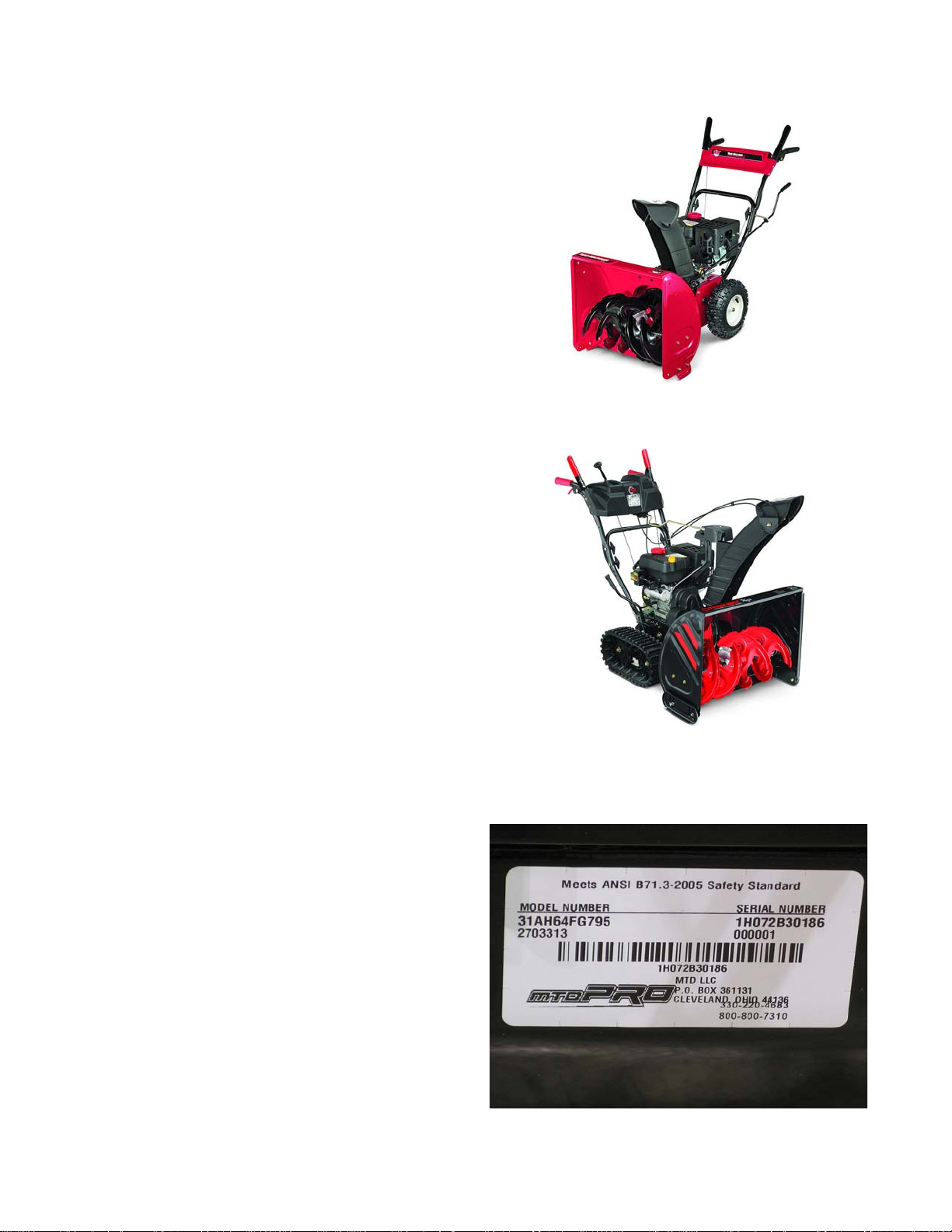
Medium Frame 2 & 3 Stage Snow Throwers
Figure 1.2
600 Series
Figure 1.3
700 Series
Figure 1.4
The 600 series features:
• Solid drive wheel axles
• Auger housing width of 22” - 30”
• 2 stage augers
The 700 series features:
• Track drive (2 and 3 wheel versions)
• Auger housing width of 24” - 30”
• 2 stage and 3 stage augers available.
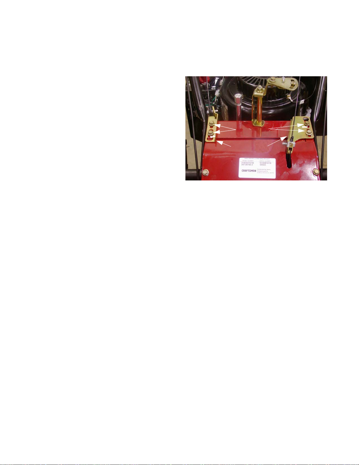
Understanding Model And Serial Numbers
The model and serial numbers are located on a white
sticker with a bar code. The sticker is located at the back of
the machine, below and to the left of the speed selector
shaft.
4
Page 9

Introduction
The model number is 31AH64FG795. The break down of what the model number
• 31 - - - - - - - - - - - - - - - - - - - - - - - - Indicates that this is a snow thrower.
• - - A- - - - - - - - - - - - - - - - - - - - - - - - Sales level
• - - - H- - - - - - - - - - - - - - - - - - - - - - - Starter (M = 110v electric starter with a 3A/5A split alternator)
• - - - - - 6 - - - - - - - - - - - - - - - - - - - - - Frame series
• - - - - - - 4 - - - - - - - - - - - - - - - - - - - - Engine (T = 277 cc Cub Cadet engine)
• - - - - - - - F- - - - - - - - - - - - - - - - - - - Handle panel style
• - - - - - - - - -G - - - - - - - - - - - - - - - - - Auger housing
• - - - - - - - - - - 795 - - - - - - - - - - - - - - Customer number
The serial number is 1H072B30186. The serial number
• 1 - - - - - - - - - - - - - - - - - -Engineering level
• - H - - - - - - - - - - - - - - - - -Month of production (H = August)
• - - - 07- - - - - - - - - - - - - - - -Day of the month
• - - - - - 2 - - - - - - - - - - - - - - -Last digit of the year
• - - - - - - B - - - - - - - - - - - - - -Plant it was built in
• - - - - - - - - 3 - - - - - - - - - - - - -Assembly line number
reads as follows:
means is as follows:
• - - - - - - - - - -0186 - - - - - - - - - -Number of unit built
Additional technical and service information may also be available to our company authorized service center personnel through our company corporate offices, regional parts distributors and regional service center field support
personnel. Please contact the designated support office in your area or our corporate offices directly should further
service information be needed.
Cub Cadet LLC
P.O. Box 368022
Cleveland, OH 44136
Telephone: (330) 273-8669
www.cubcadet.com
5
Page 10

Medium Frame 2 & 3 Stage Snow Throwers
6
Page 11
Auger Belt
Figure 2.1
3/8”
Hex Screws
Figure 2.2
Belts and Cables
Chapter 2: Belts And Cables
To remove/replace the Auger Belt:
NOTE: Prior to servicing or replacing any belts stop the
engine and allow it to cool. Then disconnect spark
plug and ground it to the engine
NOTE: If the unit is throwing the Auger Belt, inspect the
round part of the Auger Housing that the impeller
spins in. If there is a buckle or a crease in it, the
Auger Housing is bent and must be replaced
before replacing the belt.
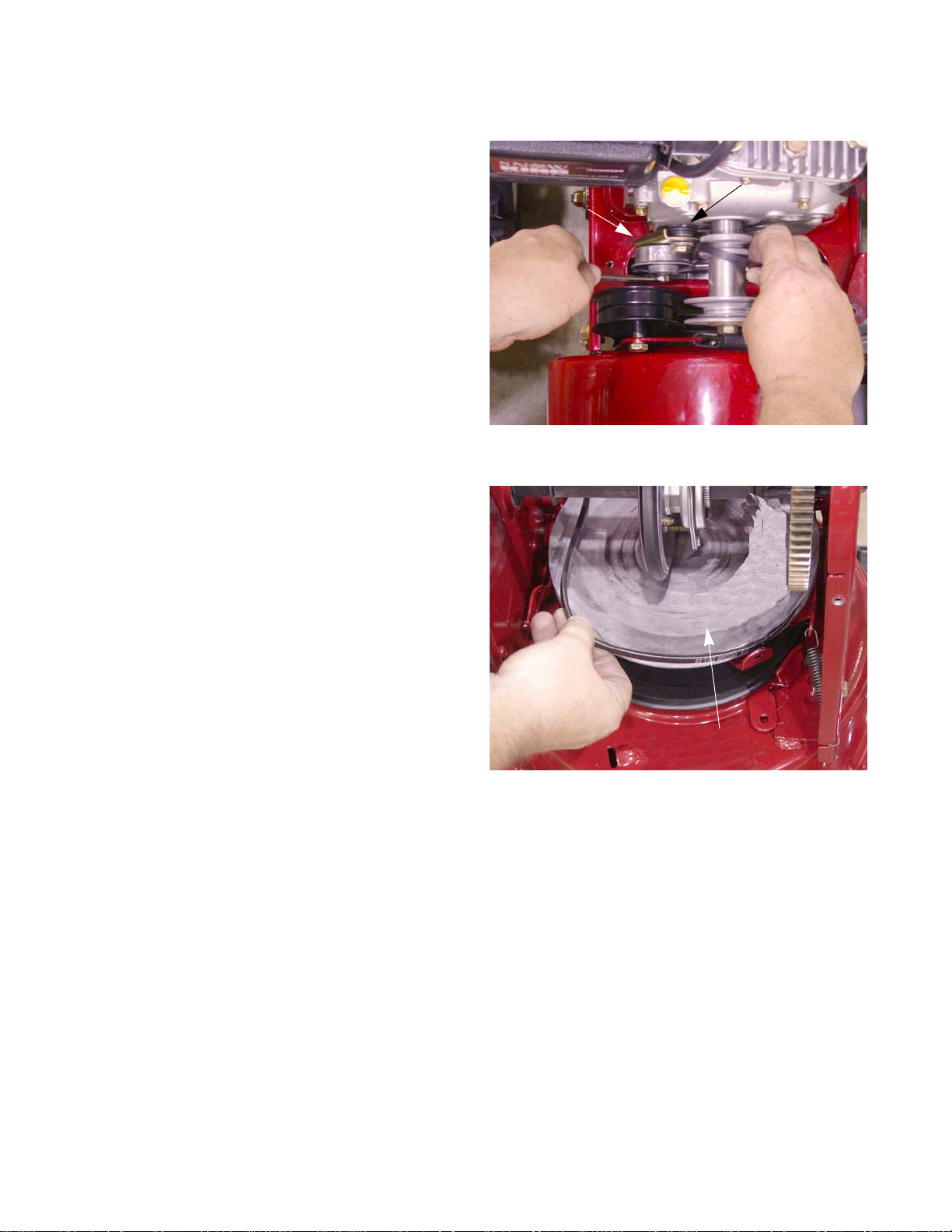
1. Remove the two screws that secure the belt cover
using a 3/8” wrench. See Figure 2.1.
2. Lift the belt cover off of the unit.
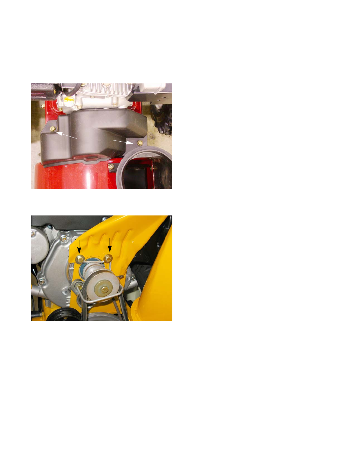
NOTE: Some units have a belt guide. The belt guide can
be removed by removing the two screws, by the
arrows in Figure 2.2., using a 1/2” wrench.
7
Page 12
Medium Frame 2 & 3 Stage Snow Throwers
Figure 2.3
Figure 2.4
3/8” wrench
Figure 2.5
Return Spring
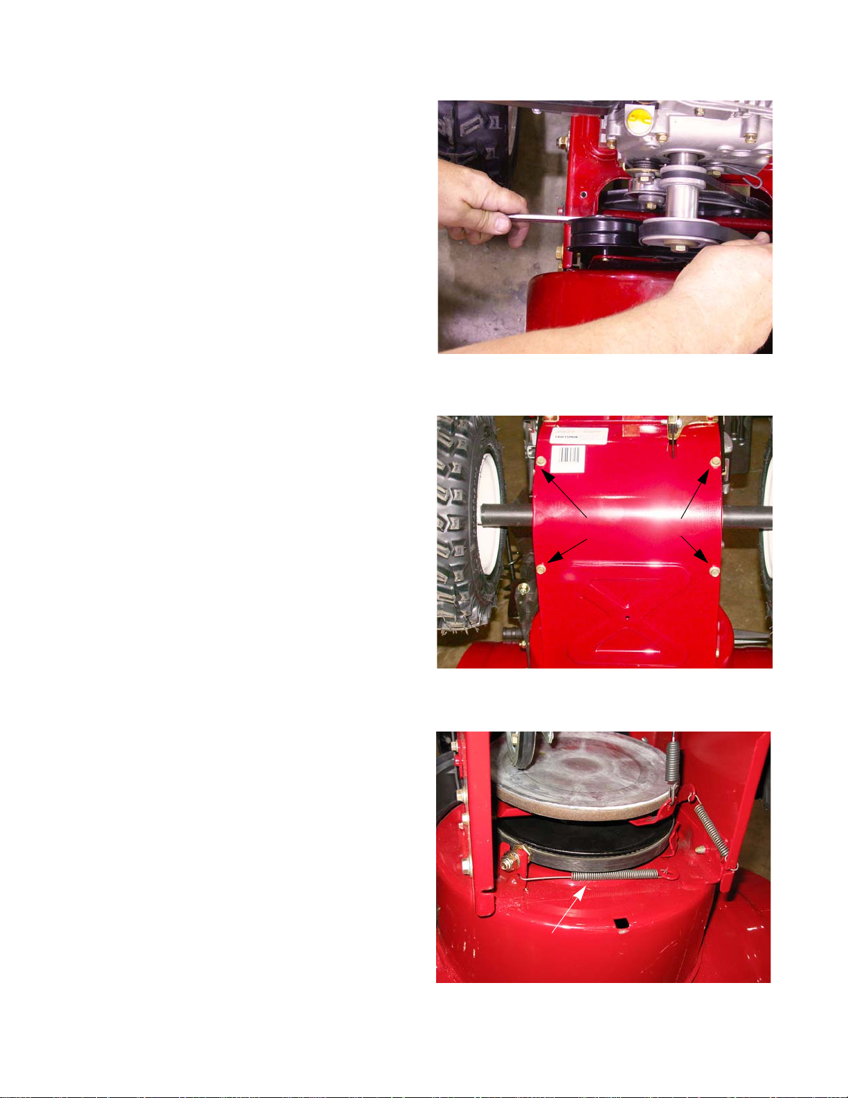
3. Loosen the idler pulley enough for the belt to cl ear it
using a 1/2” wrench.
4. Slip the belt off of the engine pulley.
5. Drain the fuel into an approved container.
6. Carefully tip the snow thrower forward so it rests on
the auger housing.
7. Remove the bottom access panel. See Figure 2.4.
8. Remove the belt guide (the shoulder bolt) with a 3/
4” wrench and a 9/16” wrench. See Figure 2.5.
9. Unhook the idler bracket return spring.
8
Page 13
Belts and Cables
Figure 2.6
Return
Spring
Figure 2.7
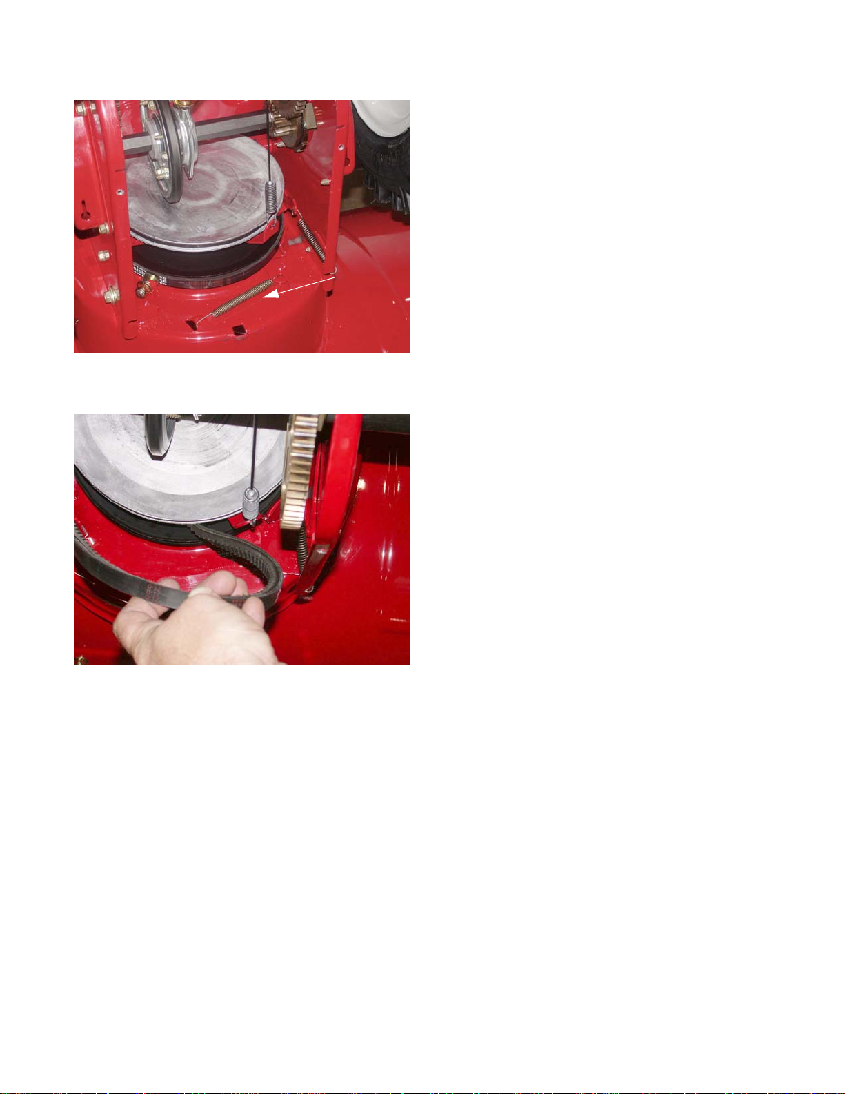
NOTE: On 2005 through 2007 model years, the Return
Spring hooked into a hole in the impeller housing.
See Figure 2.6.
NOTE: The idler bracket has a tab that acts as a brake,
pressing against the Auger Belt whenever the
Auger Control Lever is released.
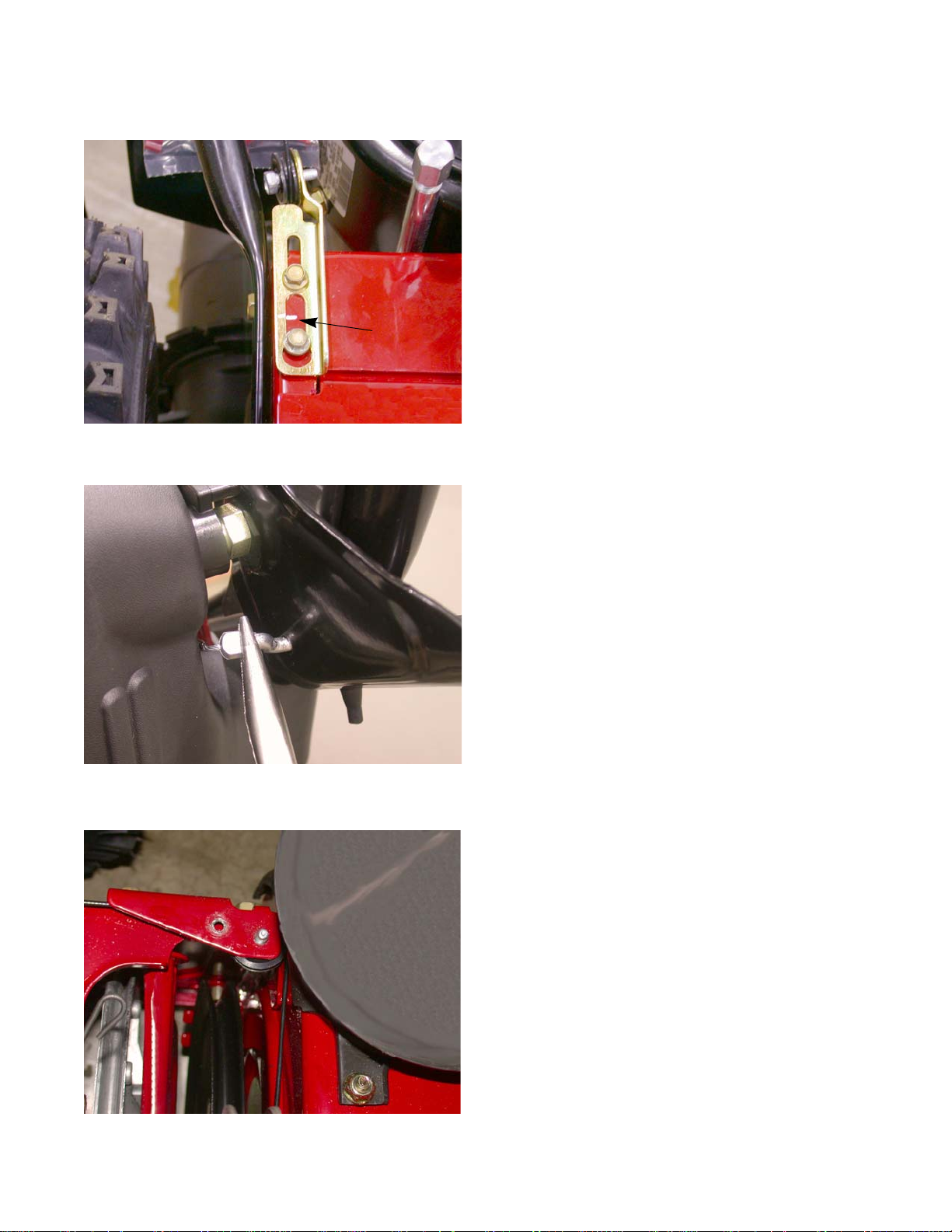
10. Pull the belt down past the Auger Pulley. See Figure
2.7.
11. Install the belt by following the previous steps in
reverse order.
12. Start the engine.
13. Engage and disengage the Auger Control Lever a
few times.
14. With the Auger Control Lever disengaged, move to
the front of the unit and verify that the augers are not
moving.
NOTE: If the Augers are moving, adjust the cable tension
and repeat steps 12 through 14.
15. Test run the snow thrower in a safe area before
returning it to service.
9
Page 14
Medium Frame 2 & 3 Stage Snow Throwers
Figure 2.8
Drive
Idler Bracket
Torsion
Spring
Figure 2.9
Drive Platter
Drive Belt
To remove/replace the drive belt:
NOTE: Prior to servicing or replacing any belt s, stop
the engine and allow it to cool. Then disconnect spark plug and ground it to the engine
1. Remove Auger Belt as described on the Auger Belt
section of this chapter.
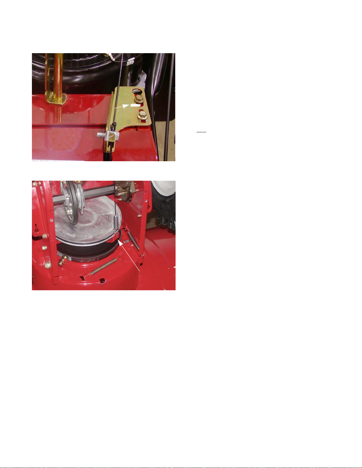
2. Using a 3/8” wrench, rotate the Drive Idler Bracket
enough slip the belt off of the engine pulley. See
Figure 2.8.
3. Work the belt off the bottom of the Drive Platter.
4. Slip the belt between the Friction Wheel and Drive
5. Pull the belt up through the top of the housing.
6. Install the belt by following the previous steps in
7. Test run the snow thrower in a safe area before
Platter. See Figure 2.9.
reverse order.
returning it to service.
10
Page 15
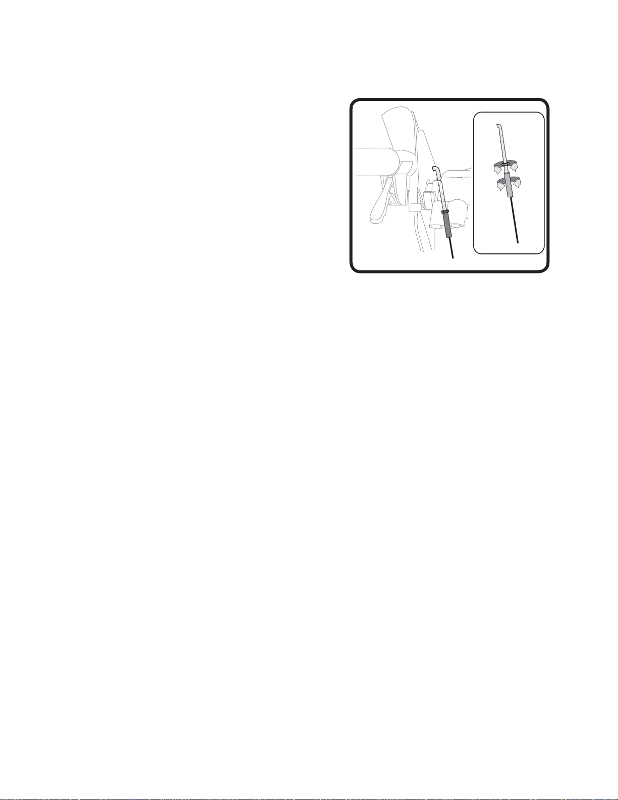
Auger Control Cable
Figure 2.10
Alignment mark
Figure 2.11
Figure 2.12
Belts and Cables
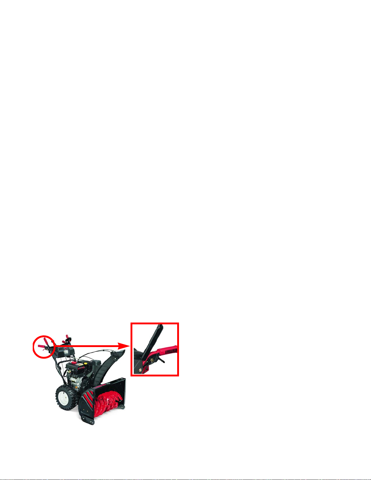
To remove/replace the Auger Control Cable:
NOTE: The auger control is on the left side of the handle
bars.
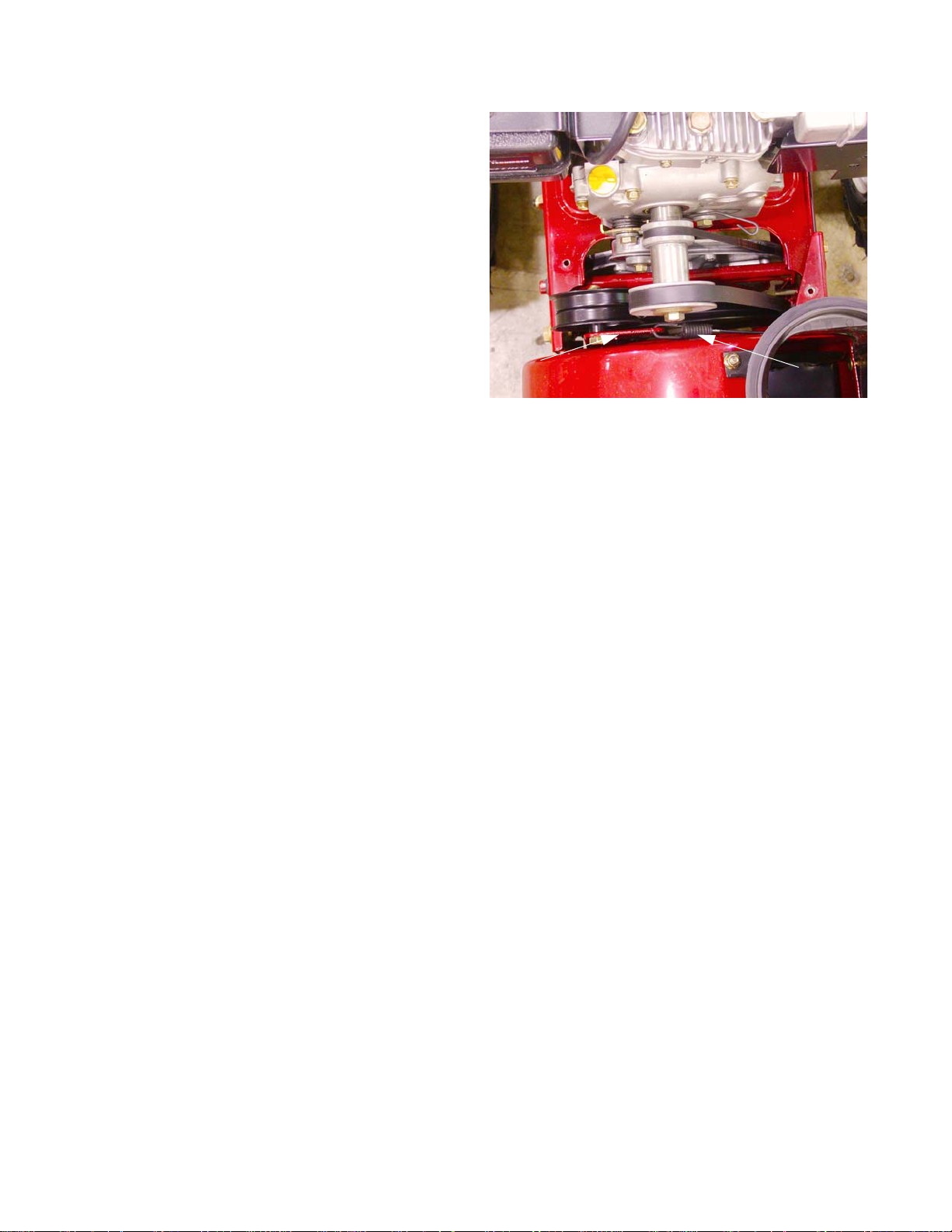
1. Place an alignment mark on the adjustment bracket
and the frame. See Figure 2.10.
2. Loosen the hex screws securing the adjustment
bracket to release tension off of the cable.
3. Detach the cable from the control handles. See Figure 2.11.
NOTE: On units with threaded Z-fittings:
• Loosen the jam nut.
• Unthread the cable from the Z-fitting.
4. Loosen the cable guide pulley on the adjustment
bracket and slip the cable out of the pulley groove.
5. Remove the belt cover.
6. Loosen the second cable guide pulley and slip the
cable out of the pulley groove. See Figure 2.12.
11
Page 16
Medium Frame 2 & 3 Stage Snow Throwers
Figure 2.13
Idler Pulley Bracket
Auger Cable
7. Detach the spring end of the cable from the Idler
Pulley Bracket. See Figure 2.13.
8. Install the cable by following the previous steps in
reverse order.
NOTE: When attaching he spring end of the cable,
the open side of the spring faces the engine.
9. Test run the snow thrower in a safe area before
returning it to service.
12
Page 17
Drive Clutch Control Cable
Figure 2.14
alignment mark
Figure 2.15
Drive platter support bracket
Belts and Cables
To remove/replace the Drive Control Cable:
NOTE: The drive control is on the right handle.
1. Stop the engine and allow it to cool. Disconnect the
spark plug wire and ground it to the engine.
2. Drain the fuel into an approved container.
3. Carefully tip the snow thrower forward so it rests on
the auger housing opening.
4. Place an alignment mark on the adjustment bracket
and
the frame. See Figure 2.14.
5. Detach the cable from the engagement handle.
NOTE: On units with threaded Z-fittings:
• Loosen the jam nut.
• Unthread the cable from the Z-fitting.
6. Remove the bottom access panel.
7. Unhook the spring end of the cable from the Drive
Platter Support Bracket. See Figure 2.15.
8. Unhook the cable from the pulley on the adjustment
bracket.
9. Install the cable by following the previous steps in
reverse order.
10. Test run the snow thrower in a safe area before
returning it to service.
13
Page 18
Medium Frame 2 & 3 Stage Snow Throwers
Figure 2.16
Hex Screws
Adjustment
Brackets
Auger and Drive Cable Adjustments (500, 600 and 3-wheel Track Drives)
NOTE: Prior to servicing or replacing any belt s, stop
the engine and allow it to cool. Then disconnect spark plug and ground it to the engine
1. Loosen the hex screws that secure the bracket that
guides the cable needing adjustment using a 3/8”
wrench. See Figure 2.16.
2. Slide the bracket up to add slack to the cable or
down to add tension to the cable.
NOTE: The cables should be straight, without ten-
sion when the handle is not engaged.
NOTE: If either bracket reaches the end of its travel
without achieving correct adjustment, use a
straight-edge to confirm that the handle bars
are not bent.
3. When adjusted correctly, the cables should not have
any slack. They should also not be under tension
while in the disengaged position.
NOTE: The speed selector sho uld be able the travel
through its full range of travel without binding.
IMPORTANT: Creep in the drive or auger systems
is unacceptable and must be fixed
before returning to service.
4. Test run the unit in a safe area before returning it to
service.
14
Page 19
Belts and Cables
Figure 2.17
Auger Cable Adjustments (2-wheel Track Drives)
Check the adjustment of the auger control:
1. When the Auger Control Lever is released, in the
disengaged or “up” position, the cable should have
very little slack. It should not be tight.
2. In a well-ventilated area, start the snow thrower
engine.
3. While standing in the operator’s position, behind the
snow thrower, engage the auger.
4. Allow the auger to remain engaged for approximately ten seconds before releasing the auger control. Repeat this several times.
5. With the throttle control in the FAST (rabbit) position
and the auger control in the disengaged or “up”
position, walk to the front of the machine.
6. Confirm that the auger has completely stopped
rotating and shows no signs of motion.
IMPORTANT: If the auger shows any signs of rotating, return to the operator’s position and shut of f the engine
and wait for all moving parts to stop before readjusting the auger control.
To adjust the Auger Control Cable:
1. Loosen the hex jam nut on the Auger Control Cable “Z” fitting. See Figure 2.17.
2. Without turning the cable, thread the ferrule up or down the “Z” fitting u ntil there is no slack in the cable without pulling on the auger idler pulley..
• Hold the flats on the ferrule with pliers and tighten the jam nut against the ferrule.
• Do not over-tighten the cable.
3. Repeat steps 2 through 6 above until proper adjustment has been achieved.
Drive Cable Adjustments (2-wheel Track Drives)
Check the adjustment of the drive control by:
1. With the Drive Control Lever released, in the disengaged or “up” position, push the snow thrower gently forward. The unit should roll freely.
2. Engage the drive control and gently attempt to push the sno w thrower forward. T he tr acks shou ld not tur n and
the unit should not roll freely.
3. Release the drive control and move the shift lever back and forth between the R2 positio n an d the F6 po sition
several times. The shift lever should move easily.
If any of the above tests failed, the drive cable is in need of adjustment. Proceed as follows:
1. To adjust the drive, loosen the hex jam nut on the auger control cable “Z” fitting. See Figure 2.17.
2. Thread the ferrule without turning the cable onto the “Z” fitting until there is no slack in the cable.
• Hold the flats on the ferrule with pliers and tighten the jam nut against the ferrule.
• Do not over-tighten the cable.
3. Rotate the coupling end of the cable counterclockwise to loosen the tension or clockwise to increase the tension on the cable.
4. Tighten the hex jam nut.
5. Re-check the adjustment of the Drive Control Cable, as described above, to verify proper a djustment has been
achieved.
15
Page 20
Medium Frame 2 & 3 Stage Snow Throwers
Figure 2.18
Figure 2.19
Figure 2.20
Speed Selector Cable
To adjust the Speed Selector Cable:
NOTE: Inspect the drive platter and friction wheel
before adjusting the speed sector cable.
Ensure that the friction wheel can freely
travel through the whole range of positions.
NOTE: A damaged or binding friction wheel can
mimic a speed selector cable that is out of
adjustment.
1. Place the shift lever in the fastest forward speed
position.
2. Loosen the hex nut on the Shift Cable Index Bracket
and pivot the bracket downward until the slack in the
cable is gone. See Figure 2.18.
3. Tighten the hex nut.
To remove/replace the Speed Selector Cable:
1. Stop the engine and allow it to cool. Disconnect the
spark plug wire and ground it to the engine.
2. Drain the fuel into an approved container.
3. Carefully tip the snow thrower forward so it rests on
the auger housing opening.
4. Remove the bottom access panel.
5. Place a block of wood on the left side of the drive
wheel to hold the shifter arm stationary. See Figure
2.19.
6. Release the tension on the Speed Selector Cable
with two 7/16” wrenches. See Figure 2.20.
NOTE: Older production units only have one hole
for the speed selector cable, as seen in Figure 2.20. Current production models have
three holes. The extra holes were added to
expand the adjustment range to the cable.
16
Page 21
Belts and Cables
Figure 2.21
Screw
Nut
Figure 2.22
Hair pin clip
Figure 2.23
7. Loosen the cable screw and nut enough to free the zfitting from the from the Speed Control Pivot Bracket.
See Figure 2.21.
8. Remove the hair pin clip from the cable end. See Figure 2.22.
NOTE: Early production units have a hex screw securing
the barrel side of the cable to the shifter handle.
NOTE: The bracket securing the cable to the shift lever is
two pieces
9. Install the cable by following the previous steps in
reverse order.
10. Adjust the cable by following the procedures
described in the Speed Control Cable adjustment
section of this chapter.
11. Test run the snow thrower in a safe area before
returning it to service.
17
Page 22
Medium Frame 2 & 3 Stage Snow Throwers
Figure 2.24
Hair Pin Clip
Figure 2.25
Speed Selector Rod
To adjust the Speed Selector Rod:
NOTE: Inspect the drive platter and friction wheel
before adjusting the Speed Selector Cable.
Ensure that the friction wheel can freely
travel trough the whole range of positions.
NOTE: A damaged or binding friction wheel can
mimic a speed selector cable that is out of
adjustment.
1. Place the Speed Selector Lever in the fastest forward speed position.
2. Remove the hair pin clip and washer from the upper
end of the selector rod. See Figure 2.24.
3. Slide the ferrule out of the speed selector leve r.
4. Loosen the jam nut.
5. Adjust the ferrule until the ferrule lines up with the
hole in the speed selector lever without pulling on
the rod. See Figure 2.25.
NOTE: When adjusted, the rod needs to be parallel
with the axis of the snow thrower.
6. Reinstall the washer and hair pin clip.
7. Test run the unit in a safe area before returning it to
service.
18
Page 23
Belts and Cables
Figure 2.26
Figure 2.27
Ball Joint
To remove/replace the Speed Selector Rod:
1. Place the shift lever in the fastest forward speed position.
2. Remove the hair pin clip and washer from the upper
end of the Selector Rod. See Figure 2.26.
3. Slide the ferrule out of the Speed Selector Lever.
4. Remove the nut that secures the ball joint on the end
of the selector rod to the selector assembly, using a
1/2” wrench. See Figure 2.27.
5. Slide the ball joint out of the Selector Assembly.
6. Install the Selector Shaft by following the previous
steps in reverse order.
NOTE: The ball joint is a wear item. MTD recommends
replacing the ball joint when installing the Speed
Selector Shaft.
7. Adjust the shaft by following the procedures
described in the previous section of this chapter.
8. Test run the unit in a safe area before returning it to
service.
19
Page 24
Medium Frame 2 & 3 Stage Snow Throwers
Figure 2.28
Alignment marks
Figure 2.29
”
3/4””
Wrench
1/2”
Wrench
Figure 2.30
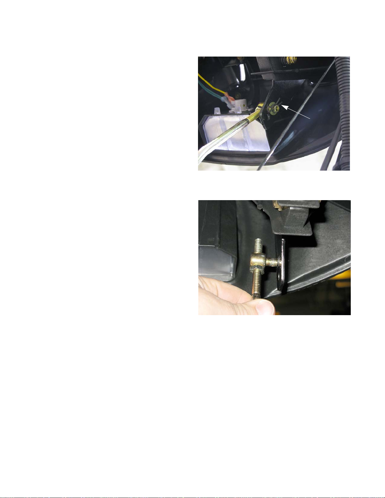
“D” hole
Auger and Drive Lever Interlock
To remove/service the Auger And Drive Lever Interlock:
1. Loosen, but do not remove the two screws ho lding
the auger cable using a 3/8” socket. See Figure
2.28.
NOTE: Place an alignment mark on the adjustment
bracket and the frame for reassembly.
2. Remove the Z-fitting from the Auger Control Lever
with a pair of needle nose pliers.
3. Remove the shoulder bolt using a 3/4” wrench and a
1/2” wrench. See Figure 2.29.
4. Carefully release the tension from the torsion spring
as the bolt is withdrawn.
5. Repeat the previous step on the drive control lever.
6. Detach the pivot rod from the Clutch Lock Cam. See
Figure 2.30.
NOTE: The flats at each end of the pivot rod fit into
the “D” hole in the cam lock.
7. Slide the rod out of the handle panel.
20
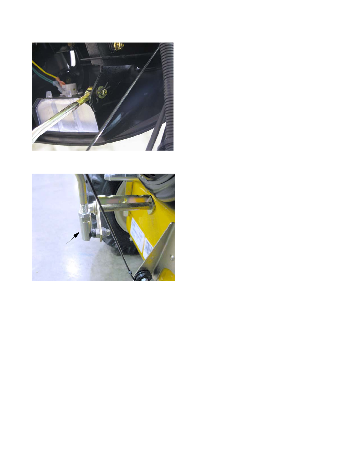
Page 25
Belts and Cables
Figure 2.31
Powdered metal end
Nail headed
Figure 2.32
Clutch Lock Cam
Shoulder nut
Hex key
NOTE: The pivot rod for early production models were nail
headed. Current production models have a powered medal end. See Figure 2.31.
NOTE: The shoulder nuts are attached to the clutch lock
cams with a socket head screw. The screw can be
removed using a 3/16” hex key.
NOTE: If the socket head screw is over torqued, the screw
head will sink into the plastic material of the Clutch
Lock Cam. The socket head screw will also prevent the shoulder bolt from threading into the
shoulder bolt all the way.
NOTE: If the socket head screw is too loose, the Clutch
Cam Lock will not operate the Auger Control
Lever.
8. Install the interlocks by following the previous procedures in reverse order.
9. Test run the unit in a safe area before returning it to
service.
21
Page 26

Medium Frame 2 & 3 Stage Snow Throwers
22
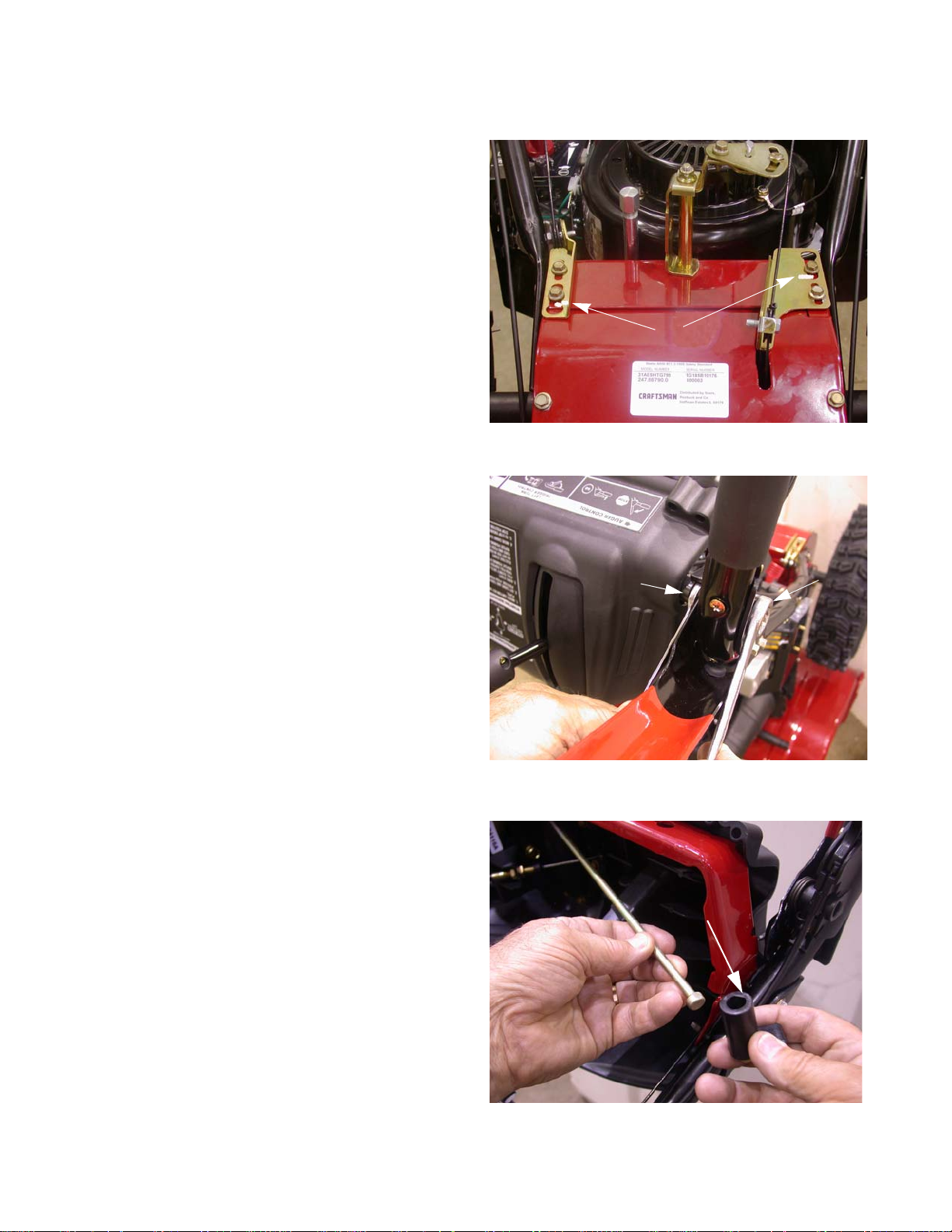
Page 27
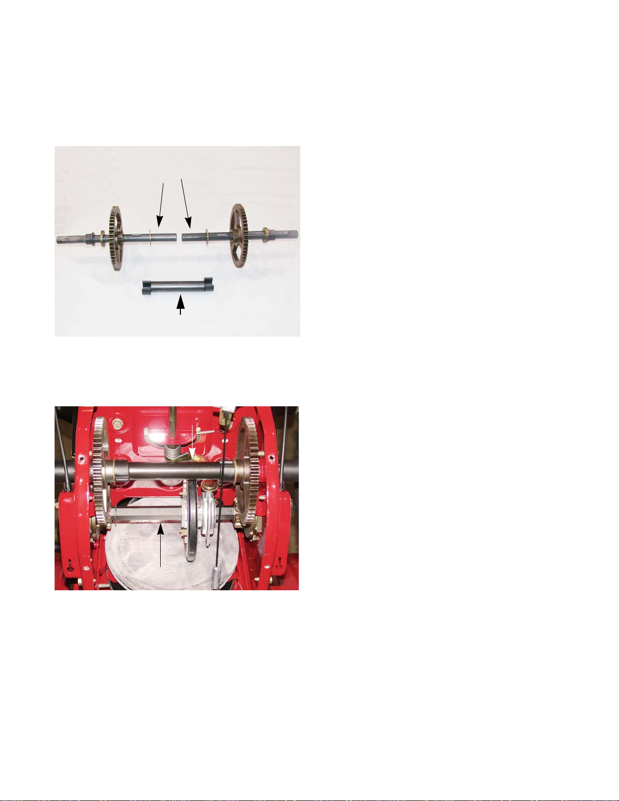
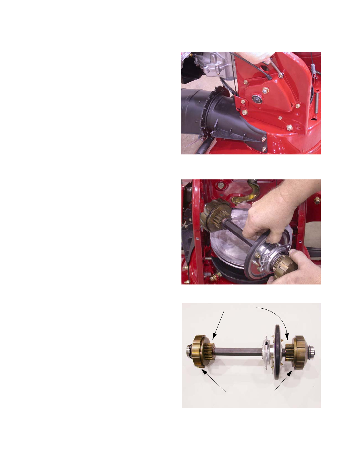
Axle Assemblies
Figure 3.1
Axle Support
Tube
Axle Shafts
Figure 3.2
Hex drive shaft
Axle
500 Series Drive System
Chapter 3: 500 Series Drive System
NOTE: Units with steerable drive wheels have a split axle
to allow each wheel to be driven independently of
each other. See Figure 3.1.
To remove the axles:
1. With the engine stopped and allowed to cool, disconnect the spark plug wire and ground it to the engine.
2. Drain the fuel into an approved container.
3. Carefully tip the snow thrower forward, so it rests on
the auger housing opening.
4. Remove the bottom access panel. See Figure 3.2.
23
Page 28
Medium Frame 2 & 3 Stage Snow Throwers
Figure 3.3
Figure 3.4
Spacer
Bushing
Hex
Figure 3.5
5. Remove the wheels using a 1/2” wrench.
NOTE: The ends of the axle shafts ar e a double -D.
See Figure 3.3.
6. Slide the spacers off of the axle. See Figure 3.4.
7. Carefully pry the 2 split bushings from the axle. See
Figure 3.5.
24
Page 29
500 Series Drive System
Figure 3.6
56 tooth gear
Spacer
Woodruff
key
8. Slide one of the large 56T gears inward, while gently
pulling the axle outward enough to expose the key
that engages the gear. See Figure 3.6.
9. Remove the key.
10. Hold the axle support tube and pull the shaf t from the
housing.
11. Repeat steps 8 through 10 for the opposite axle.
NOTE: Examine the removed parts: If failed because of
something other than normal wear, identify and
correct the cause before returning the snow
thrower to service
12. Install the axle assemblies by following the previous
steps in reverse order.
13. Test run the snow thrower in a safe area before
returning it to service.
25
Page 30
Medium Frame 2 & 3 Stage Snow Throwers
Figure 3.7
Figure 3.8
Figure 3.9
Planetary Gear Sets
Drive Gears
Hex Drive Shaft
To remove/replace a Hex Drive Shaft:
1. Stop the engine and allow it to cool, disconnect the
spark plug wire and ground it to the engine.
2. Drain the fuel into an approved container.
3. Carefully tip the snow thrower forward, so it rests on
the auger housing opening.
4. Remove the access panel using 3/8” wrench.
5. Remove both wheels using a 1/2” wrench.
6. Remove the axle assembly by following the procedure described in the previous section of this cha pter.
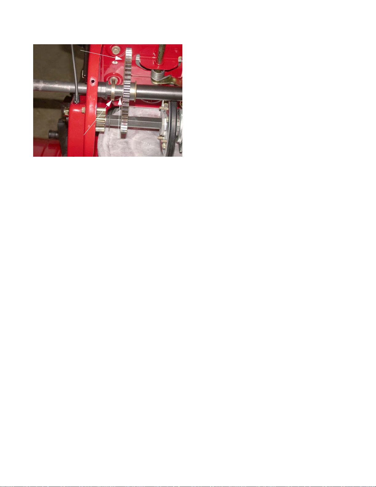
7. Remove the four screws that hold the right side
Shaft Retainer Housing. See Figure 3.7.
NOTE: In order to remove the housing, it may be
necessary to squeeze the steering trigger to
release the dog assembly from the planetary
ring gear.
8. Rotate the entire Friction Wheel Assembly backwards to it from the Shifter Assembly.
9. Maneuver the entire drive assembly to the left,
enough for the right side to clear the frame, then
remove. See Figure 3.8.
10. The complete drive assembly has two housings on
each side, commonly referred to as the planetary
gear sets. See Figure 3.9.
NOTE: Each drive gear drives one half of the split
11. Install the hex drive shaft by following the previous
steps in reverse order.
axle.
12. Test drive the snow thrower in a safe area before
returning it to service.
26
Page 31

Planetary Gears
Figure 3.10
Figure 3.11
Snap Ring
Shims
Figure 3.12
500 Series Drive System
1. To inspect or repair the planetary gears. it is not necessary to completely remove the drive assembly from
the snow thrower.
2. Stop the engine and allow it to cool, disconnect the
spark plug wire and ground it to the engine.
3. Drain the fuel into an approved container.
4. Carefully tip the snow thrower forward so it rests on
the auger housing opening.
5. Remove the wheel using a 1/2” wrench.
6. Remove the Planetary Gear Housing from the snow
thrower using a 3/8” wrench. See Figure 3.10.
7. Remove the bearing and spacer (if equipped).
8. Remove the snap ring and shims off of the shaf t. See
Figure 3.11.
NOTE: Starting with the 2013 production year, the snap
ring was changed to an E-ring.
9. Carefully remove the ring gear from the planetary
gear set. See Figure 3.12.
NOTE: The planetary gears and sun gear will slide off eas-
ily.
NOTE: Any time the carrier is taken of f o f the dr ive assem-
bly check the grease and add some Arctic Grease
(737-0318-CRTG).
27
Page 32

Medium Frame 2 & 3 Stage Snow Throwers
Figure 3.13
Ring Gear
Sun Gear
Planetary gears
Planetary gear carrier
Figure 3.14
Washer/spacer
Shims
10. Inside of each planetary gear set is a series of planetary gears that rotate aro und a sun gear and rotate
inside of the ring gear. See Figure 3.13.
NOTE: The groves are grease grooves.
11. Although the planetary gears rarely have any service issues, a good working knowledge is important.
• The hex shaft transfers torque from the rubber
drive disc to the sun gear on each end of the
hex drive shaft.
• The sun gear drives the planetary gears.
• When unlatched (trigger squeezed) the ring
gear is allowed to spin freely.
• When the ring gear spins freely it will not drive
the planetary gear carrier.
• When the trigger is released and the ring gear
is latched (prevented from rotating). The plan et
gears drive the carrier in the opposite direction
of the sun gear, but at greater speed.
12. Install the gears by following the previous steps in
13. Apply a generous coating of Arctic Grease (737-
14. Repeat on opposite side.
15. Test drive the snow thrower in a safe area before returning it to service.
• The drive gear attached to the carrier transfers
power each side of the split axle.
NOTE: Examine all the gears: If one or more of the
gears failed because of something other
than normal wear, identify and correct the
cause before returning the snow thrower to
service.
NOTE: Starting with the 2013 production year, the
needle bearings in the ring gear, were
replaced with ball bearings. Seals were also
added.
reverse order
0318-CRTG) to the inside of the ring and planetary
gears.
NOTE: When installing the bearing, remember that
the wide side faces outward. See Figure 3.14.
28
Page 33

Friction Wheel Replacement
Figure 3.15
Figure 3.16
Figure 3.17
1
2
3
4
500 Series Drive System
To remove/replace the Friction Wheel:
1. Remove the Hex Drive Shaft by following the procedures described in the Hex Drive Shaf t section of this
chapter.
2. Remove the bearing from one side of the Hex Drive
Shaft.
3. Remove the snap ring that holds the planetary gear
set to the Hex Drive Shaft.
4. Slide the planetary gear set off of the Hex Drive
Shaft.
5. Slide the Friction Wheel Assembly off of the hex
shaft.
6. Remove the four screws that hold the Friction Wheel
Assembly together using a 1/2” wrench.
NOTE: Earlier production units require 3/8” wr en ch for the
four screws.
7. Separate the friction wheel assembly.
8. Examine the removed parts.
NOTE: If it failed because of something other than normal
wear, identify and correct the cause before returning to service. See Figure 3.16.
9. Inspect the parts for damage or wear.
10. Install the rubber Friction Wheel following the previous steps in reverse order.
NOTE: Tighten the screws to in a star pattern. See Figure
3.17.
NOTE: The torque for the 1/4”-20 screws is 72 - 108 in lbs
(8 - 12 Nm).
NOTE: The torque for the 5/16”-18 screws is 115 - 145 in
lbs (13 - 16 Nm)
NOTE: Make sure the rubber ring is secure within the
wheel assembly before installing it in the unit.
NOTE: Place a small amount of 3-in-,1 or similar oil, on a
rag. Wipe a light coating of oil on the hex shaft.
11. Test run the snow thrower before returning it to service.
29
Page 34

Medium Frame 2 & 3 Stage Snow Throwers
30
Page 35

Axle Assemblies
Figure 4.1
Figure 4.2
600 Series Drive System
Chapter 4: 600 Series Drive System
1. With the engine stopped and allowed to cool, disconnect the spark plug wire and ground it to the engine.
2. Drain the fuel into an approved container.
3. Carefully tip the snow thrower forward, so it rests on
the auger housing opening.
4. Remove the bottom access panel. See Figure 4.1.
5. Remove the wheels using a 1/2” wrench.
NOTE: The ends of the axle shaft are double D.
31
Page 36

Medium Frame 2 & 3 Stage Snow Throwers
Figure 4.3
Spacer
Washers
Bushing
Hex
Figure 4.4
Woodruff Key
E-ring groove
Figure 4.5
6. Slide the spacers and washers off of the axle. See
Figure 4.3.
NOTE: There are usually 2 washers on the left side
and only 1 on the right side.
7. Remove the E-rings from the axle shaft.
NOTE: Starting in 2013, the E-rings were removed
and replaced with a 7” long split spacer.
8. Slide the axle to the left until the woodruff key in the
axle is fully exposed. See Figure 4.4.
9. Remove the woodruff key.
10. While holding the large drive gear, remove the axle
shaft from the left side.
NOTE: The washers will drop as the axle is
removed.
11. Lift the large drive gear and washers out of the
machine. See Figure 4.5.
12. Remove the hex flange bushings.
NOTE: Anytime it is necessary to remove bushings,
13. Install the axle by following the previous step in
reverse order.
14. Test run the snow thrower before returning it to service.
32
carefully inspect them for normal wear and
replace them if the wear is excessive.
Page 37

Hex Drive Shaft Assembly
Figure 4.6
Figure 4.7
13/16” Wrench
9/16”
Wrench
Figure 4.8
Drive shaft
600 Series Drive System
To remove/replace the Hex Drive Shaft Assembly:
1. Remove the Axle Assembly as described in Axle
Assemblies section of this chapter.
2. Remove the E-ring from the left side of the drive shaft
assembly. See Figure 4.6.
3. Remove the bolt or nut, depending on production
date, from the end of the hex shaft using a 9/16”
wrench while holding the shaft with a 13/16” wrench.
See Figure 4.7.
NOTE: Some units may have a 3/4” hex shaft.
NOTE: On single speed units, the drive shaf t is round. See
Figure 4.8.
33
Page 38

Medium Frame 2 & 3 Stage Snow Throwers
Figure 4.9
Collar
4. Rotate the friction wheel assembly until the collar is
free from the pin on the shift assembly.
5. Maneuver the shaft part ially through the wheel drive
frame, then tilt the assembly forward to free it from
the housing. See Figure 4.9.
6. Examine the removed parts: if any failed because o f
something other that normal wear, identify and correct the cause before returning the snow thrower to
service.
7. Install the drive shaft assembly by following the previous step in reverse order.
NOTE: Place a small amount of 3-in-1, or similar oil,
on a rag. Wipe a light coating of oil on the
hex shaft.
8. Test run the snow thrower before returnin g it to service.
34
Page 39

Friction Wheel Replacement
Figure 4.10
Roll pin
Figure 4.11
600 Series Drive System
1. Remove the drive shaft by following the procedures
described in the Hex Drive Shaft Assembly section of
this chapter.
2. Remove the bearing from one end of the shaft.
3. Slide the Friction Wheel Assembly off of the shaft.
NOTE: On the single speed models, drive out the roll pin
holding the friction wheel to the hex shaft.
4. Remove the four screws that hold the Friction Wheel
Assembly together using a 1/2” wrench.
NOTE: Earlier production units require 3/8” wr en ch for the
four screws.
5. Separate the Friction Wheel Assembly. See Figure
4.11.
35
Page 40

Medium Frame 2 & 3 Stage Snow Throwers
Figure 4.12
1
2
3
4
6. Inspect the parts for damage or wear.
7. Install the rubber Friction Wheel by following the
previous steps in reverse order.
NOTE: Tighten the screws in a star pattern. See
Figure 4.12.
NOTE: The torque for the 1/4”-20 screws is 72 - 108
in lbs (8 - 12 Nm).
NOTE: The torque for the 5/16”-18 screws is 115 -
145 in lbs (13 - 16 Nm)
NOTE: Make sure the rubber ring is secure within
the wheel assembly before installing it in the
unit.
NOTE: Place a small amount of 3-in-1 or similar oil
on a rag. Wipe a light coating of oil on the
hex shaft.
8. Test run the snow thrower before returnin g it to service.
36
Page 41

Track Adjustment
Figure 5.1
J-bolt
Front of snow thrower
Bottom of track
Note the direction
of the Track Tread
Pattern.
700 Series 2-Wheel Track-Drive System
Chapter 5: 700 Series 2-Wheel Track-Drive System
To adjust track:
1. Disconnect the spark plug wire from the spark plug
and ground against engine.
2. Drain fuel from fuel tank.
NOTE: The tension on the tracks of the snow thrower can
be adjusted. There are track adjusters on each
side of the unit. It is important that each track is
adjusted equally.
3. Tip the snow thrower forwa rd so that it rests on the
auger housing opening.
4. Loosen the front wheel nuts, using a 3/4” wrench
5. Adjust the track tension by loosening or tightening
the hex nut on J-bolts at the front of track side plates.
See Figure 5.1.
NOTE: When properly adjusted, there should be approxi-
mately 1/2” of deflection in the track with 15 lbs of
pressure applied to the track between the idler
wheel and the drive wheel assemblies.
6. Tighten the nut on the front wheels
7. Test run the unit in a safe area before returning to
service.
37
Page 42

Medium Frame 2 & 3 Stage Snow Throwers
Figure 5.2
Drive wheel
Figure 5.3
Figure 5.4
Track and Track Wheels
To remove/replace the Track and Track Wheels:
NOTE: The Track and Track Wheels are removed
and installed as one assembly.
1. Disconnect spark plug wire from spark plug and
ground it against the engine.
2. Drain the fuel tank.
3. Tip the snow thrower forward, so that it rests on its
auger housing opening.
4. Remove the nut and washer from the drive wheel
using a 3/4” wrench. See Figure 5.2.
5. Remove the nut and washer from the idler wheel
using a 3/4” wrench. See Figure 5.3.
6. Loosen the Tensioning J-bolt nuts.
7. Slide the Track and the Track Wheels off of the unit.
8. Slip the wheels out of the Track.
9. Install the Track and Track Wheels by following the
previous steps in reverse order.
NOTE: The Tracks are directional. There is an
arrow molded on the inside of the Track. The
arrow points in the direction of rotation for
forward travel. See Figure 5.4.
NOTE: The arrow was highlighted with a white paint
pen to make it visible in the photograph.
10. Adjust the track tension by following the procedures
described in the Track Adjustment section of this
chapter.
11. Test run the unit in a safe area before returning it to
service.
38
Page 43

Hex Drive Shaft
Figure 5.5
Figure 5.6
Figure 5.7
Patch bolt
700 Series 2-Wheel Track-Drive System
To remove/replace the Hex Drive Shaft:
1. Stop the engine and allow it to cool, disconnect the
spark plug wire and ground it to the engine.
2. Drain the fuel tank into an approved container.
3. Carefully tip the snow thrower forward so it rests on
the auger housing opening.
4. Remove the access panel using 3/8” wrench. See
Figure 5.5.
5. Hold the Hex Drive Shaft with a 3/4” wrench. See Figure 5.6.
NOTE: Some units may have a 7/8” hex shaft.
6. Remove the Patch Bolt and washer that secures the
right Hex Drive Shaft Bearing. See Figure 5.7.
7. Remove the bearing.
39
Page 44

Medium Frame 2 & 3 Stage Snow Throwers
Figure 5.8
Patch bolt
Figure 5.9
Figure 5.10
Shifter Arm
Pin
8. Remove the Patch Bolt and washer that secures the
left Hex Drive Shaft Bearing. See Figure 5.8.
9. Remove the bearing and spacer.
10. Slide the Hex Drive Shaft out of the unit from the
right side. See Figure 5.9.
NOTE: The Friction Wheel Assembly is now free.
Inspect and replace the Friction Wheel if
there are any signs of wear or damage.
To install the Hex Drive Shaft:
11. Verify that the Friction Wheel Assembly is engaged
with the pin on the Shifter Arm. See Figure 5.10.
40
Page 45

700 Series 2-Wheel Track-Drive System
Figure 5.11
Figure 5.12
Sprocket
Figure 5.13
Spacer
12. Slide the Hex Drive Shaft into the frame from the righ t
side, passing it through the Friction Wheel Assembly.
NOTE: The side without the E-ring goes in first.
13. Align the Hex Drive Shaft with the sprocket.
14. Pass the Hex Drive Shaft through the sprocket until
the E-ring on the shaft rests against the Fr iction
Wheel. See Figure 5.12.
15. Install the spacer on the left side of the Hex Drive
Shaft. See Figure 5.13.
16. Install the left bearing.
17. Hold the Hex Drive Shaft with a 3/4” wrench.
18. Install the washer and patch bolt.
41
Page 46

Medium Frame 2 & 3 Stage Snow Throwers
Figure 5.14
Right bearing
19. Install the bearing on the right side. See Figure
5.14.
20. Install the Patch Bolt and washer.
21. Place a small amount of 3-in-1, or similar oil, on a
rag. Wipe a light coating of oil on the Hex Drive
Shaft.
22. Install the access panel.
23. Test run the unit in a safe area before returning it to
service.
42
Page 47

Friction Wheel Replacement
Figure 5.15
Shift Arm
Figure 5.16
Figure 5.17
1
2
3
4
700 Series 2-Wheel Track-Drive System
To remove/replace the Friction Wheel:
1. Remove the Hex Drive Shaft by following the procedures described in the Hex Drive Shaf t section of this
chapter.
2. Slide the Friction Wheel Assembly off of the pin on
the Shift Arm. See Figure 5.15.
3. Remove the four screws that hold the Friction Wheel
Assembly together, using a 1/2” wrench.
NOTE: Earlier production units require a 3/8” wrench for
the four screws.
4. Separate the Friction Wheel Assembly.
5. Examine the removed parts.
NOTE: If it failed because of something other than normal
wear, identify and correct the cause before returning to service. See Figure 5.16.
6. Inspect the parts for damage or wear.
7. Install the rubber Friction Wheel following the previous steps in reverse order.
NOTE: Tighten the screws in a star pattern. See Figure
5.17.
NOTE: The torque for the 1/4”-20 screws is 72 - 108 in lbs
(8 - 12 Nm).
NOTE: The torque for the 5/16”-18 screws is 115 - 145 in
lbs (13 - 16 Nm)
NOTE: Make sure the rubber ring is secure within the
wheel assembly before installing it in the unit.
NOTE: Place a small amount of 3-in-1, or similar oil, on a
rag. Wipe a light coating of oil on the Hex Drive
Shaft.
8. Test run the snow thrower before returning it to service.
43
Page 48

Medium Frame 2 & 3 Stage Snow Throwers
Figure 5.18
Figure 5.19
Figure 5.20
Axle Shaft
To remove/replace an Axle Shaft:
1. Remove the Track and T rack Wheels of the affected
axle by following the procedures described in the
Track and Track Wheels section of this chapter.
2. Remove the bottom access panel.
3. Remove the eight screws that hold the rear aluminum housing in place, using a 1/2” wrench. See Figure 5.18.
4. Lift the housing out of the snow thrower.
5. Remove the two screws that hold the axle tube in
place, using a 1/2” wrench.
6. Move the axle so that the sprocket teeth on the axle
are beside the teeth on the Planet ary Gear Set. See
Figure 5.20.
7. Work the chain off of the sprockets.
8. Slide the axle out of the axle tube.
9. Remove the two nuts, bolts and fender washers,
that secure the axle tube to the side plate using a 1/
2” wrench and a 5/8” wrench.
10. Inspect the axle and the axle tube for signs of damage or wear. If any are found, replace the affected
component.
44
Page 49

700 Series 2-Wheel Track-Drive System
Figure 5.21
Figure 5.22
Figure 5.23
Fender washers
11. Drive out the old bushings using a drift punch. See
Figure 5.21.
12. Install new bushings in the axle tube.
13. Set the axle tube in place.
14. Slip the chain over the axle tube.
15. Slide the axle into the axle tube.
16. With the teeth of the sprocket gears next to each
other, slip the chain onto both sprockets.
17. Install the two screws that hold the axle tube in place.
18. Install the two nuts, bolts and fender washers that
secure the axle tube to the side plate using a 1/2”
wrench and a 5/8” wrench. See Figure 5.23.
19. Install the rear housing.
20. Install the access panel.
21. Install the Track and Track Wheels by following the
procedure described in the Tra ck and Track Wheel
section of this chapter.
22. Test drive the unit in a safe area befor e returning it to
service.
45
Page 50

Medium Frame 2 & 3 Stage Snow Throwers
Figure 5.24
Triggers
Figure 5.25
Figure 5.26
Planetary Gears and Shaft
To remove/replace the planetary gears and shaft:
1. Slip the chains off of both axles by following the procedures described in the Axle Shaft section of this
chapter.
2. Clamp down both steering triggers. See Figure
5.24.
3. Drive out the roll pin using a 5/32” pin punch. See
Figure 5.25.
4. Remove the nut and washer on each end of the
Planetary Shaft. See Figure 5.26.
5. Remove the Hex Flange Bushing from each end of
the shaft.
46
Page 51

700 Series 2-Wheel Track-Drive System
Figure 5.27
Figure 5.28
Figure 5.29
Shim Washers
6. Slide the Planetary Shaft to the right enough for it to
clear the transmission housing. See Figure 5.27.
7. Slip the drive chain off of the sprocket on the end of
the shaft.
8. Remove the Planetary Shaft Assembly from the
transmission box.
9. Set the shaft on the work bench. See Figure 5.28.
10. Slide the sprocket off of the shaf t.
11. Remove both chains.
12. Remove the shim washers.
13. Slide the left Planetary Gear carrier off of the shaft.
See Figure 5.29.
47
Page 52

Medium Frame 2 & 3 Stage Snow Throwers
Figure 5.30
Sun Gear
Ring Gear
Planetary Gears
Figure 5.31
Snap Ring
Figure 5.32
14. Remove the Sun Gear. See Figure 5.30.
15. Remove the Ring Gear and washer.
16. Remove the snap ring from the right Planetar y Gear
Set. See Figure 5.31.
17. Remove the shim washers.
18. Slide the right Planetary Gear Carrier off of the
shaft.
19. Remove the Sun Gear.
20. Remove the Ring Gear and washer.
21. Clean and inspect all of the components.
NOTE: If any of the Planet ary Gear Set components
show signs of wear or damage, the whole
gear set must be replaced.
22. Grease the needle bearings and the inside of the
ring gear with Arctic Grease (737-0318-CRTG).
See Figure 5.32.
NOTE: Use a liberal amount of grease. Any excess
will work its way out of the gear set.
48
Page 53

700 Series 2-Wheel Track-Drive System
Figure 5.33
Figure 5.34
Splines
Figure 5.35
Drive sprocket
23. Grease the needle bearing and the planetary gear
posts on the carrier with Arctic Grease (73 7-0318CRTG). See Figure 5.33.
24. Install the planetary gears on the carrier.
NOTE: The grooves on the planeta ry gears are for grease.
They are not timing marks.
25. Slide the washer , from behind the ring gears, onto the
shaft.
26. Grease the splines and the part of the shaft where
the needle bearings ride with Arctic Grease (7370318-CRTG). See Figure 5.34.
27. Install a Ring Gear on the right side of the shaft.
NOTE: The right side of the shaft is the side with the snap
ring groove.
NOTE: The ring gears and planetary carrier are the same
part number for each side.
28. Install a carrier with the Planetary Gears.
29. Install shim washers.
30. Install the snap ring.
31. Slide a ring gear on to the left side of the shaft.
32. Install a carrier with the planetary gears.
33. Install shim washers.
34. Slide the drive sprocket on to the left side of the shaf t.
35. Install the roll pin into drive sprocket. See Figure
5.35.
49
Page 54

Medium Frame 2 & 3 Stage Snow Throwers
Figure 5.36
36. Measure the free travel of each Planetary Gear Set
using a feeler gauge.
NOTE: There should be 0.010” - 0.030” travel.
NOTE: If there is too much travel, add a 0.020”
shim, part number 936-0502. If there is not
enough travel remove a shim.
37. Remove the roll pin, but leave the sprocket on the
shaft.
NOTE: Installing the drive chain, with the roll pin in
place, is very difficult.
38. Install the Planetary Shaft Assembly by following
step 1 - 8 in reverse order.
39. Test run the unit in a safe area before returning it to
service.
50
Page 55

Steering Trigger Cables
Figure 5.37
E-ring
Figure 5.38
Figure 5.39
Pull here
Do not pull here
700 Series 2-Wheel Track-Drive System
To remove/replace a steering trigger cable:
1. Disconnect the spark plug wire from spark pl ug and
ground it against the engine.
2. Drain the fuel tank into an approved container.
3. Tip the snow thrower forward so that it rests on its
auger housing opening.
4. Remove the E-ring that secures the steering trigger’s
Pivot Pin. See Figure 5.37.
5. Remove the Pivot Pin.
6. Unhook the trigger from the cable. See Figure 5.38.
7. Gently pry/pull the cable end out of the Trigger
Bracket.
NOTE: Do not pull on the cable jacket. It will separate from
the cable end, damaging the cable.
51
Page 56

Medium Frame 2 & 3 Stage Snow Throwers
Figure 3.40
Figure 5.41
Tabs
Planetary
pawl
Figure 5.42
Ford fuel line tool
8. Remove the bottom access panel.
9. Remove the eight screws that hold the rear aluminum housing in place, using a 1/2” wrench. See Figure 3.40.
10. Lift the housing out of the snow thrower.
11. Squeeze the tabs on the end of the cable. See Figure 5.41.
NOTE: A Ford fuel line tool is useful for squeezing
the tabs on the end of the cable. See Figure
5.42.
12. Pull the cable out of the rear plate.
13. Unhook the cable from the planetary pawls.
14. Install the cable by following the previous steps in
reverse order.
15. Test run the unit in a safe area before returning it to
service.
52
Page 57

Figure 6.1
Figure 6.2
Idler holding tool
Chapter 6: 700 Series 3-Wheel Track-Drive System
Track Removal/replacement
700 Series 3-Wheel Track-Drive System
To remove/replace the Tracks:
NOTE: There is a spring loaded idler on both tracks, that
will take up the slack in the Tracks as they stretch.
Both of the spring loaded idlers need to be held
down when doing any work or adjustments to the
Tracks. Instructions on how to build a set of tools
to hold the idlers down are located at the end of
this chapter. See Figure 6.1.
1. Drain the fuel tank into an approved container.
2. Drain the oil out of the engine.
3. Carefully tip the snow thrower forward until it rests on
the auger housing opening.
4. Install the tools to hold the idler wheel down.
NOTE: To use the tools:
• Insert the forked end of the tool over the idler arm,
between the spring and the idler wheel.
• Rotate the idler away from the Track enough for
the flange on the opposite end of the tool to hook
over the front wheel. See Figure 6.2.
• Push the tool in to fully seat it.
• Repeat on other side of the machine.
NOTE: Both Tracks must be serviced at the same time.
Failure to do so can result in non-parallel Tracks.
53
Page 58

Medium Frame 2 & 3 Stage Snow Throwers
Figure 6.3
Figure 6.4
Tensioning J-bolts
Figure 6.5
Retaining nut
5. Remove the four screws that hold the bottom
access panel in place using a 3/8” wrench.
6. Slide the panel out from under the top of the frame.
7. Rotate the panel until it is perpend icular to the frame
and slide it out of the slot in the frame. See Figure
6.3.
8. Remove the nuts from the tensioning J-bolt s using a
1/2” wrench. See Figure 6.4.
NOTE: The J-bolts will fall out when the Rear Wheel
retaining nuts are removed.
9. Remove the retaining nut from both Rear Wheels
using a 3/4” wrench. See Figure 6.5.
54
Page 59

700 Series 3-Wheel Track-Drive System
Figure 6.6
Rear Wheel
Figure 6.7
Rear Axle
Flange
Figure 6.8
Front
Bottom view
10. Slide the Rear Wheel off of the Rea r Axle. See Figure
6.6.
11. Remove the Rear Wheel.
12. Lift the Track off of the machine.
13. Repeat on the opposite side.
To install the tracks:
1. If the Rear Axle fell out, set the it on the machine so
that the flanges are inside the slots in the Track
Frame. See Figure 6.7.
2. With the idler hold-down tools still in place, set the
Track on the drive wheel and Front Wheel.
NOTE: Make sure the treads on the Tracks are facing the
right direction. See Figure 6.8.
55
Page 60

Medium Frame 2 & 3 Stage Snow Throwers
Figure 6.9
Groove
Figure 6.10
Quick Grip bar clamps
Figure 6.11
0.9”
3. Place the Rear Wheel into its groove in the Track.
4. Slide the Rear Wheel onto the Rear Axle with the
Track. See Figure 6.9.
5. Install the retaining nut a couple of threads deep.
IMPORTANT: Do not tighten the nut.
6. Repeat steps 2 through 5 on the opposite Track.
7. Lift the rear axle evenly to install the J-bolts.
NOTE: A pair of Quick Grip bar clamps in spreading
8. Install both J-bolt nuts a couple of thread deep.
IMPORTANT: Do not tighten the nuts at this time.
9. Remove the bar clamps.
10. Tighten both J-bolt nuts simultaneously, until the
ends of the J-bolts extend 0.9” from the frame. See
Figure 6.11.
mode work well for this. See Figure 6.10.
56
Page 61

700 Series 3-Wheel Track-Drive System
Figure 6.12
3/8” deflection
Pressure reading
11. Measure the Track tension:
NOTE: Track tension must be checked with the Tracks off
of the ground.
11a. Lay a straight edge across the section of Track
between the Drive Wheel and the Rear Wheel.
11b. With the idler hold-down tools installed, mea-
sure the amount of force required to cause 3/8”
deflection. See Figure 6.12.
• The reading should be 14 - 20 lbs.
• If the reading is too low , tighten both T racks evenly.
• If the reading is too high, loosen both Tracks
evenly.
NOTE: A spring loaded belt tensiometer is useful to mea-
sure the Track tension. The one shown in Figure
6.12. was purchased at: http://www.hmc-international.com/awi-i.htm
12. Tighten both Rear Wheels.
13. Install the bottom access panel.
14. Lower the unit onto the Tracks.
15. Fill the engine with oil.
16. Fill the fuel tank.
17. Test run the unit in a safe area before returning it to
service.
57
Page 62

Medium Frame 2 & 3 Stage Snow Throwers
Figure 6.13
Drive Wheel
Figure 6.14
Bearing Cup
Figure 6.15
Washer
Track Drive Assembly
To remove/replace the Track Drive Assembly:
1. Remove the Tracks by following the procedures
described in the Track remova l/replacement section
of this chapter.
2. Remove the screw that secures the Drive Wheel to
the drive axle using a 1/2” wrench.Figure 6.13.
NOTE: Engaging the Drive Control Lever will help
hold the axle while removing the screw that
secures the Drive Wheel.
3. Slide the Drive Wheel off of the axle.
4. Remove the idler holding tool.
5. Remove the three screws that secure the Drive Axle
Bearing Cup using a 3/8” wrench.Figure 6.14.
NOTE: The Track Drive Frame may drop down
when the screws are removed.
6. Remove the Bearing Cup and bearing.
7. Remove the washer that rides in the slot in the
Track Frame.
8. Lower the Track Frame until the back side of the
Front Axle clears the fork of the Height Adjusting
Arm.
9. Slip the frame off of the Rear and Drive Axles.
10. Install the Track Drive Assembly by following the
previous steps in reverse order.
11. Test run the unit in a safe area before returning it to
service.
58
Page 63

Drive Axle Assemblies
Figure 6.16
Split bushings
Figure 6.17
Key
Support Tube
Figure 6.18
Hex flange bushing
700 Series 3-Wheel Track-Drive System
To remove the Drive Axles:
1. Remove the Tracks by following the procedures
described in the Track removal/replacement section
of this chapter.
2. Remove the Track Drive As semblies by following the
procedures described in the Track Drive Assemblies
section of this chapter.
3. Remove the Split Bushings from the Drive Axle
4. Slide one of the large gears inward while gently pulling the axle outward enough to expose the key that
engages the gear. See Figure 6.17.
5. Remove the key.
6. Hold the large gear and pull the shaft from the housing.
NOTE: Keep track of the order of the washers for reas-
sembly.
7. Remove the large gear and washers.
8. Remove the Support Tube.
9. Repeat steps 4 through 7 for the opposite axle.
10. Remove the hex flange bushings. See Figure 6.18.
NOTE: Examine the removed parts. If failure was do to
something other than normal wear, identify and
correct the cause before returning the snow
thrower to service
11. Install the axle assemblies by following the previous
steps in reverse order.
12. Test run the snow thrower in a safe area before
returning it to service.
59
Page 64

Medium Frame 2 & 3 Stage Snow Throwers
Figure 6.19
Triggers
Figure 6.20
Shaft Retainer Housing
Figure 6.21
Pin
Hex Drive Shaft and Planetary Gears
To remove the Hex Drive Shaft:
1. Remove the Drive Axles by following the procedures described in the previous section of this chapter.
2. Clamp down both Steering Triggers. See Figure
6.19.
3. Remove the four screws that hold the left side
Retainer Housing. See Figure 6.20.
4. Rotate the entire Friction Wheel Assembly backwards to free the pin from the Shifter Arm.
5. Maneuver the entire drive assembly to the left
enough for the right side to clear the frame, then
remove. See Figure 6.21.
60
Page 65

700 Series 3-Wheel Track-Drive System
Figure 6.22
Bearing
Thick Washer
Thin Washer
Figure 6.23
E-ring
Figure 6.24
Thinest washer
6. Remove the bearing and washers.
NOTE: Keep track of the order of the washers for reas-
sembly. See Figure 6.22.
7. Carefully remove the E-ring that secures the Planetary Set. See Figure 6.23.
8. Slide the Planetary Gears Set off of the Hex Drive
Shaft.
9. Remove the washer that was behind the Gear Set.
NOTE: The washer behind the Gear Set is the thinnest of
the three washers. See Figure 6.24.
10. Slide the Friction Wheel Assembly off of the Hex
Drive Shaft.
11. Repeat steps 6 through 9 on the opposite side of the
Hex Drive Shaft.
61
Page 66

Medium Frame 2 & 3 Stage Snow Throwers
Figure 6.25
Ring Gear
Planetary Gears
Planetary Gear Carrier
Figure 6.26
Sun gear
Figure 6.27
Ring gear
12. Inside of each Planetary Gear Set is a series of
Planetary Gears that rotate around a Su n Ge ar and
rotate inside of the Ring Gear. See Figure 6.25.
NOTE: The groves are grease grooves.
13. Although the Planetary Gears rarely have any service issues, a good working knowledge is important.
• The Hex Drive Shaft transfers torque from the
Friction Wheel to the Sun Gear on each end of
the Hex Drive Shaft.
• The Sun Gear drives the Planetary Gears.
• When unlatched, trigger squeezed, the Ring
Gear is allowed to spin freely .
• When the Ring Gear spins freely it will not drive
the Planetary Gear Carrier.
• When the trigger is released and the Ring Gear
is latched, preventing it from rotating. The
Planet Gears drive the carrier in the opposite
direction of the Sun Gear, but at greater speed.
• The Drive Gear attached to the carrier transfers
power to the Axle Half.
NOTE: Inspect the component, replace/repair as
needed.
14. Slide the Friction Wheel Assembly onto the Hex
Drive Shaft so that the hole for the pin, on the shifte r
arm, is away from the E-ring on the shaft.
15. Install the thin washer and Planetary Carrier.
16. Install the Sun and Planetary Gears. See Figure
6.26.
17. Apply a generous coating of Arctic Grease (7370318-CRTG) to the inside of the Ring Gear and on
the gears.
18. Install the Ring Gear, E-ring, washers and bearing.
See Figure 6.27.
19. Repeat steps 15 through 18 on the opposite side.
20. Install the Hex Drive Shaft assembly by following
steps 1 through 5 in reverse order.
21. Coat the hex section of the Hex Drive Shaft with a
22. Test drive the snow thrower in a safe area before
62
generous coating an anti-seize compound.
returning it to service.
Page 67

Friction Wheel Replacement
Figure 6.28
Figure 6.29
Figure 6.30
1
2
3
4
700 Series 3-Wheel Track-Drive System
To remove/replace the Friction Wheel:
1. Remove the Hex Drive Shaft by following the procedures described in the Hex Drive Shaf t section of this
chapter.
2. Remove the bearing and washers from one side of
the Hex Drive Shaft.
3. Remove the E-ring that holds the Planetary Gear Set
to the Hex Drive Shaft.
4. Slide the Planetary Gear Set and washer off of the
Hex Drive Shaft. See Figure 6.28.
NOTE: The washer behind the gear set is the thinest of
the three washers. See Figure 6.24.
5. Slide the Friction Wheel Assembly off of the Hex
Drive Shaft.
6. Remove the four screws that hold the Friction Wheel
Assembly together using a 1/2” wrench.
7. Separate the Friction Wheel Assembly.
8. Inspect the parts for damage or wear. Replace parts
as needed
NOTE: If it failed because of something other than normal
wear, identify and correct the cause before returning to service. See Figure 6.29.
9. Install the rubber Friction Wheel following the previous steps in reverse order.
NOTE: Tighten the screws in a star pattern. See Figure
6.30.
NOTE: The torque for the 1/4”-20 screws is 72 - 108 in lbs
(8 - 12 Nm).
NOTE: The torque for the 5/16”-18 screws is 115 - 145 in
lbs (13 - 16 Nm)
NOTE: Make sure the rubber ring is secure within the
wheel assembly before installing it in the unit.
NOTE: Coat the hex section of the Hex Drive Shaft with a
generous coating an anti-seize compound.
10. Test run the snow thrower before returning the it to
service.
63
Page 68

Medium Frame 2 & 3 Stage Snow Throwers
Figure 6.31
Bolt heads
Forked end
Long side of angle bracket
145o angle
Idler Hold Down Tools
Two tools are needed to hold down the spring loaded
idlers. The components needed to assemble the tools are:
• (2) forked angle brackets (50 x 55 mm).
• (2) angle brackets (45 x 55mm).
• (2) 5.25” x 1” x 0.25” pieces of flat stock steel.
• (8) 1/4” x 20 x 5/8” bolts
• (8) 1/4” x 20 nuts
NOTE: The print for the angle brackets and the flat
stock is on the next page.
NOTE: The stock angle brackets used to make
these tools came from the manufacturer with
metric dimensions. The flat stock is manufactured with SAE dimensions.
1. Assemble the components to form two tools that are
mirror images of each other. See Figure 6.31.
NOTE: Install the bolts so that the bolt heads are on the insid e. See Figure 6.31.
NOTE: Note wrapping the parts of the tool that make contact with the idler bracket and the wheel, will mini-
mized the chance of scratching the components while using the tool.
64
Page 69

28 mm
25 mm
15 mm 15 mm
15 mm
15 mm
15 mm
27.5 mm
20 mm
1”
5.25”
11 mm
4 mm
10 mm
27 mm
12.5 mm
11 mm
44 mm
12.5 mm
11 mm 11 mm
55 mm
45 mm
45 mm
50 mm
50 mm
65 mm
700 Series 3-Wheel Track-Drive System
Flat stock should be 0.25” thick
2 Angle brackets. 10 gauge steel minimum 2 Angle brackets. 10 gauge steel minimum
NOTE: All holes are 0.25”
65
Page 70

Medium Frame 2 & 3 Stage Snow Throwers
66
Page 71

Auger Housing and Gear Box
Figure 7.1
Reversible
Reversible
Reversible
Non-Reversible
Figure 7.2
Nuts
Chapter 7: Auger Housing and Gear Box
NOTE: The Shave Plate and Skid Shoes on the bottom of the snow thrower are subject to wear. They should
be checked periodically and replaced when necessary.
Skid Shoes
NOTE: There is a variety of Skid Shoes available for
medium frame snow throwers. Most of them are
reversible. See Figure 7.1.
To remove the Skid Shoes:
1. Remove The Hex Flange Nuts which secure the Skid
Shoe to the snow thrower.
2. Slide the Skid Shoe off of the carriage bolts
3. Repeat steps 1 and 2 on the opposite side.
4. Install the new skid shoes by following the previous
steps in reverse order.
.
Skid Shoe Adjustment
NOTE: Leave the nuts loose until the skid shoes are
adjusted.
5. Adjust the Skid Shoes by following the procedures in
the Skid Shoe Adjustment section of this chapter.
To adjust the skid shoes:
1. On flat ground place a 1/16” shim under the shave
plate.
NOTE: The shim needs to run the length of the shave
plate.
NOTE: A piece of cardboard work fine for shimming the
shave plate. See Figure 7.2.
2. Loosen the nuts on the skid shoes.
NOTE: On track units, place the transport lever in the nor-
mal operation position.
3. Push the skid shoes down until they rest on the
ground.
4. Tighten the skid shoe nuts.
67
Page 72

Medium Frame 2 & 3 Stage Snow Throwers
Figure 7.3
Figure 7.4
Adjustable slot
Shave Plate
To remove/replace the Shave Plate:
1. Drain the fuel from the fuel tank.
2. Tip the snow thrower back enough to access the
shave plate.
NOTE: Laying the snow thrower on its back will
cause the engine cylinder to fill with oil.
3. Remove the nuts and carriage bolts (indicated by
the arrows in Figure 7.3.) that hold the Shave Plate
to the Auger Housing using a 1/2” wrench.
NOTE: The Shave Plate on a Heavy Duty Housing
can be adjusted as it wears. See Figure 7.4.
4. Install the Shave Plate by following the previous
steps in reverse order.
5. Test run the snow thrower in a safe area before
returning it to service.
68
Page 73

Auger Housings
Figure 7.5
3/8”
Hex Screws
Figure 7.6
Figure 7.7
Pivot point
Auger Housing and Gear Box
To remove/replace the Auger Housing:
1. Disconnect and ground the spark plug wire.
2. Remove the Discharge Chute by following the procedures described in appropriate discharg e chute chapter.
3. Remove the two screws that secure the belt cover
using a 3/8” wrench. See Figure 7.5.
4. Lift the Belt Cover off of the unit.
5. Loosen the Idler Pulley enough for the belt to clear it
using a 1/2” wrench. See Figure 7.6.
6. Slip the belt off of the Engine Pulley.
7. Remove the four screws that hold the Auger Housing
to the transmission using a 1/2” wrench. See Figure
7.7.
NOTE: The snow thrower will split in two when the screws
are removed.
69
Page 74

Medium Frame 2 & 3 Stage Snow Throwers
Figure 7.8
Figure 7.9
Chute Collar
Return Spring
Idler Braket
Belt Guide
Figure 7.10
Barbs
NOTE: On 2-Wheel Track units:
• Remove the six nuts that hold the Auger Housing to the transmission box using a 1/2” wrench.
See Figure 7.8.
8. Separate the Auger Housing from the transmission
box.
9. Disconnect the Auger Control Cable from the Idler
Bracket.
10. Remove the Auger Gear Box Assembly by following
the procedures described in the Auger Assemblies
removal section of this chapter.
11. Remove the four nuts and bolts that hold the Chute
Collar to the Auger Housing using a 7/16” wrench.
See Figure 7.9.
12. Unhook the Idler Bracket Return Spring.
13. Remove the Idler Bracket using a 15/16” wrench
14. Remove the Belt Guide (shoulder bolt), using a 3/4”
15. Remove the Chute Clean-out Tool holder, by
16. Install the Auger Housing by following the previous
17. Test run the snow thrower in a safe area before
and a 9/16” wrench.
wrench and a 9/16” wrench.
squeezing the split barbs together while pushing
them out of the housing. See Figure 7.10.
steps in reverse order.
returning it to service.
70
Page 75

Auger Assemblies
Figure 7.11
Figure 7.12
Pivot point
Figure 7.13
Auger Housing and Gear Box
To remove/replace the Auger Assembly:
NOTE: The procedures for removing/replacing the Auger
Assemblies are basically the same for a 2-stage
and a 3-stage unit. Any differences will be covered
when they arise.
1. Separate the Auger Housing from the Transmission
Box by following the procedures described in th e
Auger Housing section of this chapter.
2. Remove the Auger Belt.
3. Use a block of wood to prevent the augers from turning. See Figure 7.11.
4. Remove the bolt that attaches the Auger Pulley to the
Auger Shaft using a 1/2” wrench. See Figure 7.12.
5. The Pulley Adapter should slide off of the shaft easil y .
See Figure 7.13.
71
Page 76

Medium Frame 2 & 3 Stage Snow Throwers
Figure 7.14
Figure 7.15
Figure 7.16
E-ring
6. Remove the screws holding the Bearing Housing on
each side. See Figure 7.14.
NOTE: This is a good opportunity to inspect the
Auger Bearing for signs of wear.
7. Pull the auger from the housing. Slight rotation of
the assembly may be necessary to pull the Impeller
Shaft clear of the rear bearing. See Figure 7.15.
NOTE: The most common cause of Auger Gear-
Box damage is an impact with solid objects.
This damage is not warrantable. Use of
proper Shear Pins helps prevent gearbox
damage, but does not guarantee protection.
8. Remove the Bearing Cup, Hex Flange Bushing and
washer from each end of the output shaft.
NOTE: Some models may have an E- ring that holds
the bushing to the end of the shaft. See Figure 7.16.
72
Page 77

Auger Housing and Gear Box
Figure 7.17
Accelerator
Figure 7.18
Flange bushings
Spacers
Hex Bushing
Figure 7.19
NOTE: 3-stage units have augers on the fro nt and back o f
the Gear Box called Accelerators. See Figure 7.17.
9. Pry off the front cap.
10. Remove the screw and washer from the end of the
Input Shaft.
11. Remove the Shear Pin.
12. Slide the Accelerator, washer and spacer off of the
front of the Gear Box.
13. Slide the impeller of f of the D section of th e Gear Box
Input Shaft.
NOTE: If the unit is a 3-stage gear box, remove the rear
Accelerator.
14. Remove the shear pins.
15. Slide the augers and spacers off of the Gear Box
Assembly.
NOTE: Note the orientation and location of all of the spac-
ers as they are removed.
16. Inspect the spacers and bushin gs. Check for possible
damage to augers. See Figure 7.18.
17. Examine the removed Auger Assembly: If it failed;
because of something other than normal wear, identify and correct the cause before returning the snow
thrower to service.
18. Install the Auger Assembly by following the previous
steps in reverse order.
NOTE: When the augers are installed correctly, the fore-
most blades will have an inward slant. See Figure
7.19.
19. Test run the snow thrower in a safe area before
returning to service.
73
Page 78

Medium Frame 2 & 3 Stage Snow Throwers
Figure 7.20
Fill Plug
Figure 7.21
Figure 7.22
2-Stage Gear Boxes
To rebuild a 2-stage Gear Box:
1. Remove the Gear Box by following the procedures
described in the Auger Assemblies section of this
chapter.
2. Gently pry out the Fill Plug. See Figure 7.20.
3. Turn the transmission over and drain any oil into an
approved container.
NOTE: The transmission is filled with grease, but
the grease will break down and release its oil
over time.
4. Remove the five screws, that hold the housing
halves together, using a 3/8” wrench. See Figure
7.21.
5. Separate the housings.
NOTE: The housings have silicone se alant on them.
It may be necessary to cut the sealant to
separate the housings. See Figure 7.22.
74
Page 79

Auger Housing and Gear Box
Figure 7.23
Input Shaft
Figure 7.24
Figure 7.25
6. Remove the Input Shaft Assembly.
7. Disassemble the Input Shaft Assembly.
NOTE: The Input Shaft might be a little swollen at the dou-
ble D, preventing the bushing and collar from sliding off. If necessary, file down the swollen area
until the bushing clears.
8. Inspect the shaft, bushings, pin and collar. If there are
any signs of wear or damage, replace the affected
part(s).
9. Remove the Output Shaft, washers and Worm Gear.
NOTE: There is a washer on each side of the Worm Gear.
Sometimes the washers stick to the housing when
they are separated.
10. Slide the Worm Gear off of the Output Shaft.
1 1. Inspect the shaft, key and gear. If there are any signs
of wear or damage, replace the affected part(s).
75
Page 80

Medium Frame 2 & 3 Stage Snow Throwers
Figure 7.26
Seal
Figure 7.27
Figure 7.28
Seal lip faces out
12. Remove the seals from the housings.
13. Thoroughly clean the housings an d re m ov e all of
the old sealant.
14. Press new seals into the housings. See Figure 7.26.
15. Reassemble the Output Shaft, Worm Gear and
washers.
16. Insert the Output Shaft Assembly into one of the
housings. See Figure 7.27.
17. Reassemble the Input Shaft Assembly with a new
seal.
18. Install the Input Shaf t As semb ly into th e same hous ing that has the Output Shaft. See Figure 7.28.
76
Page 81

Auger Housing and Gear Box
Figure 7.29
Figure 7.30
Thin bead of sealant
19. Apply 1.5 - 2 oz of 737-0168A grease to the gears
and inside of the housing. See Figure 7.29.
20. Work the gears to distribute the grease between
them.
21. Apply a small bead of Loctite Ultra Grey, or similar
sealant, along the inside of the bolt holes on one of
the housings. See Figure 7.30.
NOTE: A small bead is all that is needed. A thick bead of
sealant is a waste of sealant and can cause
excess sealant to get into the bearings.
22. Slide the second housing in place.
23. Install the five screws. Tigh ten them to a torque of 90
- 120 in lbs (10 - 14 Nm).
24. Install the plastic plug.
25. Install the Gear Box by following the procedures
described in the Auger Assemblies section of this
chapter.
26. Test run the unit in a safe area before returning it to
service.
77
Page 82

Medium Frame 2 & 3 Stage Snow Throwers
Figure 7.31
Cover
Figure 7.32
Snap Ring
Figure 7.33
Key
3-Stage Gear Boxes
To rebuild a 3-stage Gear Box:
1. Remove the Gear Box by following the procedures
described in the Auger Assemblies section of this
chapter.
2. Remove the four screws that secure the cover to the
gear box housing using a 3/8” wrench. See Figure
7.31.
3. Gently lift the cover off of the Gear Box.
4. Drain the gear box into an approved container.
5. Remove the left seal, as viewed from the opera tor’s
position.
6. Remove the snap ring. See Figure 7.32.
7. Gently drive the Output Shaft out of the Gear Box
from right to left.
NOTE: The key on the Output Shaft will drive out
the left bearing. See Figure 7.33.
78
Page 83

Auger Housing and Gear Box
Figure 7.34
Snap Ring
Figure 7.35
Worm Gear
Figure 7.36
8. Remove the rear Input Shaft (long side) Seal.
9. Remove the snap ring. See Figure 7.34.
10. Remove the Input Shaft fro m the rear of the Gear
Box.
11. Lift the Worm Gear out of the Gear Box. See Figure
7.35.
12. Drive out the right side bearing.Figure 7.36.
13. Remove the seal.
79
Page 84

Medium Frame 2 & 3 Stage Snow Throwers
Figure 7.37
Figure 7.38
Figure 7.39
14. Drive out the front bearing.Figure 7.37.
15. Remove the seal.
16. Clean and dry all components.
17. Inspect the components.
NOTE: If there are signs of wear or damage,
replace the affected component(s).
18. Install the front bearing, using a brass punch to seat
it. See Figure 7.38.
NOTE: The front Bearing Pocket does not have a
snap ring grove, the rear does.
19. Install the right bearing, using a brass punch to seat
it. See Figure 7.39.
NOTE: The left Bearing Pocket has a snap ring
grove, the right does not.
80
Page 85

Auger Housing and Gear Box
Figure 7.40
Figure 7.41
Short end
Rear Bearing
Front Bearing
Figure 7.42
Snap Ring
20. Set the Worm Gear inside the housing. See Figure
7.40.
21. Insert the Input Shaft into the housing so that the
short end rests in the front bearing. See Figure 7.41.
22. Install the rear bearing.
23. Install the rear snap ring. See Figure 7.42.
81
Page 86

Medium Frame 2 & 3 Stage Snow Throwers
Figure 7.43
Figure 7.44
Snap Ring
Figure 7.45
Oil level
24. Insert the key into the Output Shaft.
25. Insert the Output Shaft into the housing from the lef t
side, passing it through the Worm Gear. See Figure
7.43.
26. Rotate the Output Shaft until the key lines up with
the slot in the Worm Gear.
27. Push the shaft into the housing until the key passes
into the Worm Gear.
28. Install the left bearing.
29. Install the left snap ring. See Figure 7.44.
30. Install new seals for all four bearings.
31. Holding the Gear Box level, fill it with 4 oz of Cub
Cadet Drive System Plus (737-3120). See Figure
7.45.
32. Install a new cover gasket.
33. Install the Gear Box Cover. Tighten the screws to a
torque of 90 - 120 in lbs (10 - 14 Nm).
34. Install the gear box by following the procedures
described in the Auger Assemblies section of this
chapter.
35. Test run the unit in a safe area before returning it to
service.
82
Page 87

Figure 8.1
Figure 8.2
Chapter 8: Discharge Chute and Controls (Manual Crank)
Remote Pitch Control Head (Plastic Chutes)
Discharge Chute and Controls (Manual Crank)
To remove/replace the Remote Pitch Control Head:
NOTE: The Remote Pitch Control Head consists of a
Cable Guide, Cable Guide Bracket, and the cables
that run to the pitch control lever/joystick.
1. Remove the wing nut and carriage bolt that holds the
left side of the Chute Deflector to the Discharge
Chute.
2. Remove the nut (indicated by the arrow in Figure 8.1)
and the carriage bolt that holds the right side of the
chute deflector to the discharge chute using a 1/2”
wrench.
3. Remove the screw, indicated by the arrow in Figure
8.2, that anchors the Cable Guide to the Discharge
Chute using a 3/8” wrench.
4. Slide the Chute Deflector off of the snow thrower.
83
Page 88

Medium Frame 2 & 3 Stage Snow Throwers
Figure 8.3
Cable guide
Cable bracket
Figure 8.4
Mark the cable
and bracket
Figure 8.5
5. Slide the Cable Guide out from in between the
Cable Bracket and the Discharge Chute. See Figure
8.3.
6. Disconnect the cables from the cable guide.
7. Mark one of the cables and its location in the Cable
Bracket. See Figure 8.4.
8. Unhook the cable assemblies from the Chute
Deflector.
9. Remove both of the cables.
To install the Chute Deflector:
1. Hook the Cable Bracket onto the Chute Deflector.
2. Install both of the cables into the proper slots in the
Cable Bracket as indicated by the arrows in Figure
8.5
NOTE: Forward movement of pitch contro l leve r/
joystick should result in the Chute Deflector
moving down.
NOTE: If the cables are reversed, the chute opera-
3. Insert the Cable Guide in between the Cable
Bracket and the chute.
84
tion will be reversed.
Page 89

Discharge Chute and Controls (Manual Crank)
Figure 8.6
Cable ends
4. Attach the cables to the Cable Guide. See Figure 8.6.
5. Slide the Chute Deflector onto the Discharge Chute.
NOTE: Do not apply grease to the inside surface of the
Chute Deflector or the outside surface of the Discharge Chute.
6. Install the carriage bolts and nuts that hold the Chute
Deflector to the Discharge Chute.
NOTE: Thread the nuts on to the car riage bolt s until a cou-
ple of threads stick out past the nylon locking feature. Do not over tighten the nut s.
7. Install the screw that anchors the Cable Guide to the
Discharge Chute.
8. Test run the snow thrower in a safe area before
returning it to service.
85
Page 90

Medium Frame 2 & 3 Stage Snow Throwers
Figure 8.7
Figure 8.8
Figure 8.9
Cable Guide
Cable Bracket
Remote Pitch Control Head (Steel Chutes)
T o remove/att ach the Pitch Control Head to/from the Chute
Deflector:
NOTE: The Remote Pitch Control Head consists of
a Cable Guide, Cable Guide Bracket, and
the cables that run to the pitch control lever/
joystick.
1. Remove the wing nut, washer and carriage bolt that
holds the left side of the Chute Deflector to the Discharge Chute.
2. Remove the nut, indicated by the arrow in Figure
8.7, and the carriage bolt that holds the right side of
the Chute Deflector to the Discharge Chute using a
1/2” wrench.
3. Remove the screw, indicated by the arrow in Figure
8.8, that anchors the Cable Guide to the Discharge
Chute using a 3/8” wrench.
4. Slide the Chute Deflector off of the snow thrower.
5. Mark one of the cables and its location in the Cable
Bracket and Cable Guide. See Figure 8.9.
6. Slide the Cable Guide out as far as it will go.
7. Disconnect both cables from the Cable Bracket.
NOTE: The Cable Bracket can not be removed from
or install on the Chute Deflector with the
cables attached.
86
Page 91

Discharge Chute and Controls (Manual Crank)
Figure 8.10
Figure 8.11
Figure 8.12
Cable Jacket End
8. Disconnect the cables from the Cable Guide. See
Figure 8.10.
9. Unhook the Cable Bracket from the Chute Deflector.
To install the Chute Deflector:
1. Hook the Cable Bracket onto the Chute Deflector.
See Figure 8.11.
2. Attach both cables to the Cable Guide.
NOTE: Forward movement of pitch control lever/joystick
should result in the Chute Deflector moving down.
NOTE: If the cables are reversed, the chute operation will
be reversed.
3. Slide the Cable Guide in between the Chute Deflector and the Cable Bracket.
4. Insert the Cable Jacket Ends into the slots in the
Cable Bracket. See Figure 8.12.
87
Page 92

Medium Frame 2 & 3 Stage Snow Throwers
Figure 8.13
Wiper
Figure 8.14
5. Set the Chute Wiper in place.
6. Set the Chute Deflector on the chute.
7. Align the deflector and the chute by inserting a carriage bolt through the chute, wiper, deflector, Cable
Guide and the Cable Bracket. See Figure 8.13.
NOTE: Do not apply grease to the inside surface of
the Chute Deflector or the outside surface of
the Discharge Chute.
8. Install the nut on the carriage bolt installed in the
previous step.
NOTE: Thread the nuts on to the car riage bolt s until
a couple of threads stick out past the nylon
locking feature. Do not over tighten the nuts.
9. Install the carriage bolt and wing nut on the left side
of the deflector.
10. Install the screw that anchors the Cable Guide to
the Discharge Chute.
11. Test run the snow thrower in a safe area before returning it to service.
88
Page 93

Discharge Chute and Controls (Manual Crank)
Figure 8.15
Flange Keeper
Discharge Chute (Manual Crank, Cork Screw Style)
To remove/replace the Discharge Chute:
1. Pry open the three Flange Keepers securing the discharge chute to the chute adapter.Figure 8.15
2. Lift the chute assembly off the mounting base of the
main housing.
NOTE: If the unit is equipped with remote pitch control,
refer to the Remote Pitch Control Head section to
remove the control head.
To install the chute:
1. Position the chute over the base.
2. Close the Flange Keepers to secure the chute to the
base.
NOTE: If the Flange Keepers will not easily click into
place, use the palm of your hand to apply swift,
firm pressure to the back of each one.
89
Page 94

Medium Frame 2 & 3 Stage Snow Throwers
Figure 8.16
Hair Pin Clip
Figure 8.17
Bow Tie Clip
Wing Nut
Figure 8.18
Lock nuts
Discharge Chute (with Remote Head)
1. Remove the hair pin clip that secures the shaft from
the hand crank or joystick, if equipped. See Figure
8.16.
2. Remove the bow tie clip.
3. Remove the clevis pin that holds the Remote Head
to the Support Bracket. See Figure 8.17.
4. Remove the wing nut.
NOTE: Units with a steel chute have a lock nut
instead of a wing nut. See Figure 8.18.
NOTE: Units with a steel chute have the nut, for the
bolt that attaches the remote head to the
chute, exposed. It must be held with a 7/16”
wrench during step 5.
90
Page 95

Discharge Chute and Controls (Manual Crank)
Figure 8.19
Figure 8.20
Figure 8.21
Separate
5. Remove the bolt that secures the Remote Head to
the Discharge Chute. See Figure 8.19.
6. The Discharge Chute will lift off of the Chute Collar.
See Figure 8.20.
7. Separate the Remote Head from the chute. See Figure 8.21.
8. Install the chute by following the previous steps in
reverse order.
NOTE: Some early production units with a remote head
had Flange Keepers. If there were Flange Keepers
on the discharge chute remove and discard them.
Do not install them when installing the chute.
9. Test run the snow thrower in a safe area before
returning it to service.
91
Page 96

Medium Frame 2 & 3 Stage Snow Throwers
Figure 8.22
Hair Pin Clip
Washer
Chute Crank Bracket
Figure 8.23
Manual Crank, Cork Screw Style
To remove/replace the Chute Crank:
1. Remove the flat washer and hair pin clip from the
end of the Chute Crank. See Figure 8.22.
2. Remove the wing nut from the eye bolt that att aches
the crank to the handle.
3. Slide the eye bolt out of the handle
4. Pull the crank out of the Chute Bracket.
5. Install the crank by following the previous steps in
reverse order.
6. Adjust the Chute Bracket as necessary to ensure
the spiral of the crank is fully engaged with the
chute.
7. Test run the snow thrower in a safe area before
returning it to service.
Chute Bracket Adjustment
To adjust the Chute Bracket:
1. Loosen the two nuts, which secure the Chute Crank
Bracket to the Chute Collar. See Figure 8.23.
2. Position the Chute Bracket so that the spiral of the
crank is fully engaged with the chute.
3. Tighten the nuts, securing the bracket.
4. Test run the snow thrower in a safe area before
returning it to service.
92
Page 97

Remote Head
Figure 8.24
Figure 8.25
Separate
Figure 8.26
Flat Washer
Discharge Chute and Controls (Manual Crank)
To disassemble a manual crank Remote Head:
NOTE: Procedures for rigid and flexible shaft Remote
Heads are the same.
1. Remove the hair pin clip that attaches the crank to
the Remote Head.
2. Slide the shaft out of the Remote Head.
3. Remove the bolt that attaches the Remote Head to
the chute using a 1/2” wrench. See Figure 8.24.
4. Remove the wing nut from the underside of the
Remote Head.
5. Remove the bow tie clip and clevis pin that secures
the Remote Head to the Support Mast.
6. Lift the Remote Head and chute off of the machine.
7. Separate the Remote Head from the chute. See Figure 8.25.
NOTE: There is a flat washer between the Remote Head
and the chute. If this washer is missing, the
Remote Head may bind. See Figure 8.26.
93
Page 98

Medium Frame 2 & 3 Stage Snow Throwers
Figure 8.27
Figure 8.28
Pinion Gear
Figure 8.29
Worm Gear
8. Move the remote head to a workbench for service.
9. Remove the four screws that hold the Gear Support
to the cover using a 5/16” wrench. See Figure 8.27.
10. Lift the Gear Set out of the Remote Head Cover.
See Figure 8.28.
11. Lift the Pinion Gear out of the Gear Set.
12. Lift the Worm Gear and shaft out of the Gear Support Bracket. See Figure 8.29.
13. Remove the Pinion Gear Bushing.
94
Page 99

Discharge Chute and Controls (Manual Crank)
Figure 8.30
Figure 8.31
Figure 8.32
Alignment Mark
Hole
14. Insert a pick or similar tool into the hole in the Gear
Shaft while removing the nut with a 9/16” wrench.
See Figure 8.30.
15. Remove the hex bushings, spring and washers from
the shaft.
To assemble the Remote Head:
1. Slide the Worm Gear onto the Gear Shaft so that the
alignment mark is facing and is aligned with the holes
in the gear shaft.
NOTE: Slide the gear onto the shaft from the side with the
holes.
95
Page 100

Medium Frame 2 & 3 Stage Snow Throwers
Figure 8.33
Figure 8.34
3/4”
Figure 8.35
Flat Washer
2. Install the large holed washers and hex bushings
onto the gear shaft.
3. Install the small holed washers and the spring onto
the Gear Shaft.
4. Install the lock nut. Tighten it to a torq ue of 35 - 50 in
lbs (4 - 6 Nm). See Figure 8.33.
5. Install the Pinion Bushing in the Gear Support
Bracket.
6. Install the Gear Shaft Assembly into to Support
Bracket.
7. Test the Gear Shaft for binding.
NOTE: It should take 20 in lbs of torque to rot ate the
shaft. The lock nut on the shaft can be tightened to increase the resistance or loosened
to decrease the resistance.
8. Set the Pinion Shaft into the Gear Set so that the
travel stop is 3/4” from the edge of the bracket. See
Figure 8.34.
9. Set the Gear Set into the Remote Head Housing.
NOTE: Lubricate all friction surfaces with Renolit
Polar Grease part number 937-04085.
10. Install the four screws that secure the ho using to the
Support Bracket. Tighten the screws to a torque of
20 - 30 in lbs (2 - 3 Nm).
11. Attach the Remote Head to the chute.
NOTE: Ensure that the flat washer is trapped
between the Pinion Gear and the chute. See
Figure 8.35.
12. Set the Remote Head and chute on the machine.
13. Install the wing nut, bow tie clip and clevis pin that
secures the Remote Head to the mast.
14. Slide the crank into the Remote Head.
15. Install the hair pin clip that attaches the shaft to the
Remote Head.
16. Test run the snow thrower in a safe before returning
it to service.
96
 Loading...