

Page 1

FORM NUMBER 769-00903
88445544 SSEERRVVIICCEE M
MAANNUUAALL
MTD Products, LLC Product Training and Education Department
Page 2

Page 3

CONTENTS
CHAPTER 1. GENERAL INFORMATION ........................................................................................1-1
1. TRACTOR VIEW............................................................................................................................................... 1-3
2. TIGHTENING TORQUE FOR STANDARD BOLTS AND NUTS ................................................................. 1-4
2.1 TIGHTENING TORQUE........................................................................................................................ 1-4
3. SPECIFICATIONS............................................................................................................................................ 1-6
4. IDENTIFICATIONS........................................................................................................................................... 1-8
4.1 ENGINE NUMBER ................................................................................................................................ 1-8
4.2 SERIAL NUMBER OF THE TRACTOR ............................................................................................... 1-8
5. CAUTION BEFORE REPAIR .......................................................................................................................... 1-9
5.1 BEFORE REPAIR OR INSPECTION .................................................................................................. 1-9
5.2 ASSEMBLY AND DISASSEMBLY......................................................................................................... 1-9
5.3 PARTS TO BE REPLACED.................................................................................................................. 1-9
5.4 PARTS..................................................................................................................................................... 1-9
5.5 ASBESTOS P ARTS .............................................................................................................................1-10
5.6 ELECTRICAL SYSTEM....................................................................................................................... 1-10
5.7 TUBES AND RUBBERS ..................................................................................................................... 1-11
5.8 LUBRICANT ......................................................................................................................................... 1-11
6. REGULAR CHECK LIST............................................................................................................................... 1-12
7. OIL & WATER SUPPLY LIST........................................................................................................................ 1-13
CHAPTER 2. ENGINE ........................................................................................................................2-1
1. GENERAL ......................................................................................................................................................... 2-3
1.1 APPEARANCE....................................................................................................................................... 2-3
1.2 SPECIFICATIONS .................................................................................................................................2-4
1.3 PERFORMANCE CURVE..................................................................................................................... 2-5
1.4 DIMENSIONS......................................................................................................................................... 2-6
1.5 GENERAL WARNING ........................................................................................................................... 2-6
2. STRUCTURE AND FUNCTION ..................................................................................................................... 2-7
2.1 BODY ...................................................................................................................................................... 2-7
2.2 LUBRICATION SYSTEM..................................................................................................................... 2-11
2.3 COOLING SYSTEM............................................................................................................................. 2-13
2.4 FUEL SYSTEM..................................................................................................................................... 2-15
2.5 INTAKE AND EXHAUST SYSTEM...................................................................................................... 2-22
3. DISASSEMBLING AND SERVICING .......................................................................................................... 2-24
3.1 TROUBLIE SHOOTING...................................................................................................................... 2-24
3.2 SERVICING SPECIFICA TIONS......................................................................................................... 2-27
3.3 CHECKING, DISASSEMBLING AND SERVICING..........................................................................2-33
Page 4

CHAPTER 3. CLUTCH ....................................................................................................................... 3-1
1. TROUBLE SHOOTING.................................................................................................................................... 3-3
2. SPECIFICATIONS,TIGHTENING TORQUES AND SPECIAL TOOLS ...................................................... 3-4
2.1 SPECIFICATIONS .................................................................................................................................3-4
2.2 TIGHTENING TORQUES ..................................................................................................................... 3-4
2.3 SPECIAL TOOLS................................................................................................................................... 3-4
3. STRUCTURE AND OPERATION ................................................................................................................... 3-5
3.1 FEATURES ............................................................................................................................................. 3-5
3.2 STRUCTURE......................................................................................................................................... 3-5
3.3 OPERATION........................................................................................................................................... 3-6
4. PREPARA TION STAGE FOR DISASSEMBLING AND ASSEMBLING........................................................ 3-7
4.1 SEP ARATING PANEL FRAME ASSEMBL Y... ... . . ... . ... . . ... . ... . . ... . ... . . ... . ... . . ... . ... . ... . . ... . ... . . ... . ... . . ... . ... . . ... . . 3-7
4.2 SEPARATING ENGINE AND CLUTCH HOUSING CASE................................................................. 3-9
4.3 DISASSEMBLY..................................................................................................................................... 3-10
5. ADJUSTMENT OF PEDALS ......................................................................................................................... 3-11
5.1 DEFLECTION OF CLUTCH PEDAL ................................................................................................. 3-11
5.2 CLEARANCE BETWEEN SAFETY STAR TING SWITCH AND LINK............................................. 3-11
6. INSPECTION AND REPAI R..........................................................................................................................3-12
6.1 WEAR AND DAMAGE ON CLUTCH DISC ....................................................................................... 3-12
6.2 CLEARANCE BETWEEN SPLINE BOSS OF THE CLUTCH DISC AND
SHUTTLE SHAFT SPLINES.............................................................................................................. 3-12
6.3 FLATNESS OF CLUTCH PRESSURE PLATE, DAMAGES............................................................3-13
6.4 DAMAGES T O FLYWHEEL, ADJUSTMENT OF RELEASE BEARING.. .... ....................................3-13
6.5 WEAR OR DAMAGES ON RELEASE BEARING, RELEASE FORK AND RELEASE HUB ........ 3-13
6.6 CLEARANCE BETWEEN CLUTCH PEDAL SHAFT AND CLUTCH PEDAL BUSHING ............3-14
CHAPTER 4. TRANSMISSION SYSTEM ........................................................................................4-1
1. TROUBLESHOOTING..................................................................................................................................... 4-3
1.1 TROUBLESHOOTING FOR SHUTTLE SHIFT IN OPERATION ERROR ...................................... 4-3
1.2 TROUBLESHOOTING FOR MAIN SHIFTS IN OPERATION ERROR ............................................ 4-3
1.3 TROUBLESHOOTING FOR AUXILIARY AND CREEP SHIFTS IN OPERATION ERROR........... 4-4
1.4 TROUBLESHOOTING FOR REAR DIFFERENTIAL GEAR IN OPERA TION ERROR ................. 4-4
1.5 TROUBLESHOOTING FOR REAR DIFFERENTIAL IN OPERATION ERROR............................. 4-4
1.6 TROUBLESHOOTING FOR FRONT WHEEL DRIVE IN OPERATION ERROR ........................... 4-5
1.7 TROUBLESHOOTING FOR PTO CLUTCH IN OPERATION ERROR ........................................... 4-5
1.8 TROUBLESHOOTING FOR PTO IN OPERATION ERROR............................................................. 4-5
1.9 TROUBLESHOOTING FOR PARKING BRAKE IN OPERATION ERROR...................................... 4-5
2. SPECIFICATIONS............................................................................................................................................ 4-6
2.1 TIGHTENING TORQUES ..................................................................................................................... 4-6
3. STRUCTURE ................................................................................................................................................... 4-7
3.1 POWER TRAIN DIAGRAM.................................................................................................................... 4-7
3.2 STRUCTURE......................................................................................................................................... 4-8
Page 5

3.3 POWER TRAIN ...................................................................................................................................... 4-9
3.3.1 TRANSMISSION......................................................................................................................... 4-9
3.3.2 SHUTTLE SHIFT SECTION ................................................................................................... 4-10
3.3.3 MAIN SHIFT .............................................................................................................................. 4-11
3.3.4 AUXILIARY SHIFT .................................................................................................................... 4-12
3.3.5 FRONT WHEEL DRIVE........................................................................................................... 4-12
3.3.6 PTO SHIFT................................................................................................................................4-13
3.4 OPERATION ......................................................................................................................................... 4-14
3.4.1 FEATURES.................................................................................................................................4-14
4. PREPARATION STAGE FOR DISASSEMBLING AND ASSEMBLING TRANSMISSION........................ 4-22
4.1 DRAINING THE TRANSMISSION FLUID......................................................................................... 4-22
4.2 SEPARATING PANEL FRAME ASSEMBLY ....................................................................................... 4-23
4.3 SEPARATING REAR FENDERS AND PLATFORM ASSEMBLY ..................................................... 4-25
5. TO DISMANTLE AND TO ASSEMBLE ......................................................................................................... 4-28
5.1 STANDARD TABLE FOR REPAIR ..................................................................................................... 4-28
5.2 TO DISMANTLE AND TO ASSEMBLE............................................................................................... 4-28
6. DIFFERENTIAL GEAR ................................................................................................................................... 4-55
6.1 STRUCTURE....................................................................................................................................... 4-55
6.2 OPERATION ......................................................................................................................................... 4-56
6.3 LOCKING OF THE DIFFERENTIAL GEAR ...................................................................................... 4-57
CHAPTER 5. FRONT AXLE ...............................................................................................................5-1
1. TROUBLESHOOTING..................................................................................................................................... 5-3
2. SPECIFICATIONS ............................................................................................................................................ 5-4
3. STRUCTURE ................................................................................................................................................... 5-6
3.1 OPERATION ........................................................................................................................................... 5-6
3.2 FRONT WHEEL ALIGNMENT.............................................................................................................. 5-7
3.3 TOE-IN ADJUSTMENT.......................................................................................................................... 5-8
3.4 DIRECTION CONTROL ANGLE FOR THE FRONT WHEEL .......................................................... 5-8
3.5 ROCKING FORCE OF THE FRONT AXLE, DEFLECTION IN FRONT & REAR DIRECTIONS.. 5-9
4. PREPARATION STAGE FOR DISASSEMBLING AND ASSEMBLING...................................................... 5-10
4.1 SEPARATING FRONT AXLE.............................................................................................................. 5-10
5. TO DISMANTLE AND TO ASSEMBLE ......................................................................................................... 5-12
5.1 FRONT AXLE CASE AND FRONT AXLE........................................................................................... 5-12
5.2 BEVEL GEAR CASE AND FRONT AXLE CASE .............................................................................. 5-13
5.3 BEVEL GEAR CASE AND FRONT AXLE SUPPORT......................................................................5-14
5.4 FRONT AXLE SUPPORT AND DIFFERENTIAL GEAR CASE....................................................... 5-15
5.5 FRONT DIFFERENTIAL GEAR ......................................................................................................... 5-16
5.6 FRONT BRACKET .............................................................................................................................. 5-19
5.7 REAR BRACKET ................................................................................................................................. 5-20
Page 6

CHAPTER 6. HYDRAULIC SYSTEMS.............................................................................................6-1
1. HYDRAULIC LIFT SYSTEM............................................................................................................................ 6-3
1.1 TROUBLE SHOOTING ......................................................................................................................... 6-5
1.2 SPECIFICATIONS .................................................................................................................................6-6
1.3 STRUCTURE AND OPERATION......................................................................................................... 6-9
1.4 PREPARA TION STAGE FOR DISASSEMBLING AND ASSEMBLING ........................................... 6-25
1.5 DISMANTLE AND ASSEMBLING....................................................................................................... 6-27
2. PTO CLUTCH VALVE SYSTEM..................................................................................................................6-38
2.1 SPECIFICA TIONS AND DIAGRAM ....................................................................................................6-38
2.2 STRUCTURE AND OPERATION.......................................................................................................6-39
2.3 ASSEMBLING AND DISASSEMBLING .... .. .. .....................................................................................6-44
2.4 TO CHECK AND TO REPAIR............................................................................................................. 6-46
3. POWER STEERING SYSTEM......................................................................................................................6-47
3.1 TROUBLE SHOOTING......................................................................................................................... 6-47
3.2 INTRODUCTION ................................................................................................................................. 6-48
3.3 STRUCTURE AND OPERATION.......................................................................................................6-50
3.4 PREPARA TION STAGE FOR DISASSEMBLING AND ASSEMBLING ........................................... 6-55
3.5 TO DISMANTLE AND TO ASSEMBLE............................................................................................... 6-58
4. HYDRAULIC PUMP ....................................................................................................................................... 6-66
4.1 TROUBLESHOOTING ........................................................................................................................ 6-66
4.2 SPECIFICATIONS ...............................................................................................................................6-66
4.3 STRUCTURE AND OPERATION.......................................................................................................6-67
4.4 TO DISMANTLE AND TO ASSEMBLE............................................................................................... 6-69
5. HYDRAULIC FILTER..................................................................................................................................... 6-71
5.1 STRUCTURE AND OPERATION.......................................................................................................6-71
6. HYDRAULIC PRESSURE OPERATION PRINCIPLE AND TROUBLE SHOOTING .............................6-73
6.1 COMPOSITION OF HYDRAULIC DEVICE & FLOW DIAGRAM OF HYDRAULIC OIL................6-73
6.2 STEERING DEVICES .........................................................................................................................6-75
6.3 PTO SYSTEM....................................................................................................................................... 6-77
6.4 HYDRAULIC PRESSURE RISE & FALL DEVICE...........................................................................6-79
CHAPTER 7. BRAKE..........................................................................................................................7-1
1. TROUBLESHOOTING..................................................................................................................................... 7-3
2. SPECIFICATIONS............................................................................................................................................ 7-3
3. TIGHTENING TORQUE .................................................................................................................................. 7-4
4. STRUCTURE AND OPERATION ................................................................................................................... 7-5
4.1 STRUCTURE......................................................................................................................................... 7-5
4.2 OPERATION........................................................................................................................................... 7-7
5. DISASSEMBLING AND ASSEMBLING .......................................................................................................... 7-8
5.1 DRAINING THE TRANSMISSION FLUID........................................................................................... 7-8
5.2 SEP ARATING PANEL FRAME ASSEMBL Y... ... . . ... . ... . . ... . ... . . ... . ... . . ... . ... . . ... . ... . ... . . ... . ... . . ... . ... . . ... . ... . . ... . . 7-9
Page 7

5.3 SEP ARATING REAR FENDERS AND PLA TFORM ASSEMBL Y..................................................... 7-11
5.4 DISASSEMBLING REAR AXLE CASE ..............................................................................................7-14
5.5 DISASSEMBLING BRAKE CASE ...................................................................................................... 7-15
6. ADJUSTMENT OF THE BRAKE................................................................................................................... 7-16
7. SERVICING ....................................................................................................................................................7-17
CHAPTER 8 ELECTRIC SYSTEM ....................................................................................................8-1
1. ELECTRONIC INSTRUMENTA TION............................................................................................................. 8-3
1.1 INSTRUMENT GAUGE............................................................................................................................ 8-3
1.2 INDICA TORS AND WARNING LIGHTS................................................................................................. 8-4
2. TROUBEL SHOOTING.................................................................................................................................... 8-6
3. SERVICING SPECIFICATIONS ..................................................................................................................... 8-8
4. MECHANISM..................................................................................................................................................... 8-9
4.1 STARTING SYSTEM ................................................................................................................................ 8-9
4.2 CHARGING SYSTEM.............................................................................................................................8-12
4.3 PREHEATING SYSTEM......................................................................................................................... 8-14
4.4 FUSE ....................................................................................................................................................... 8-15
4.5 GAUGE AND SENSORS .......................................................................................................................8-16
CHAPTER 9. CABIN SYSTEM .........................................................................................................9-1
1. DISASSEMBLY AND ASSEMBLY.................................................................................................................... 9-3
2. HEATER ............................................................................................................................................................ 9-8
2.1 STRUCTURE......................................................................................................................................... 9-8
2.2 DISASSEMBLY AND ASSEMBLY......................................................................................................... 9-8
2.3 HEATER OPERATION DEVICE........................................................................................................... 9-8
3. AIR CONDITIONER ......................................................................................................................................... 9-9
3.1 AIR CONDITIONER .............................................................................................................................. 9-9
3.2 TROUBLE SHOOTING ....................................................................................................................... 9-13
Page 8

Page 9

CHAPTER 1
GENERAL INFORMATION
Page 10

Page 11
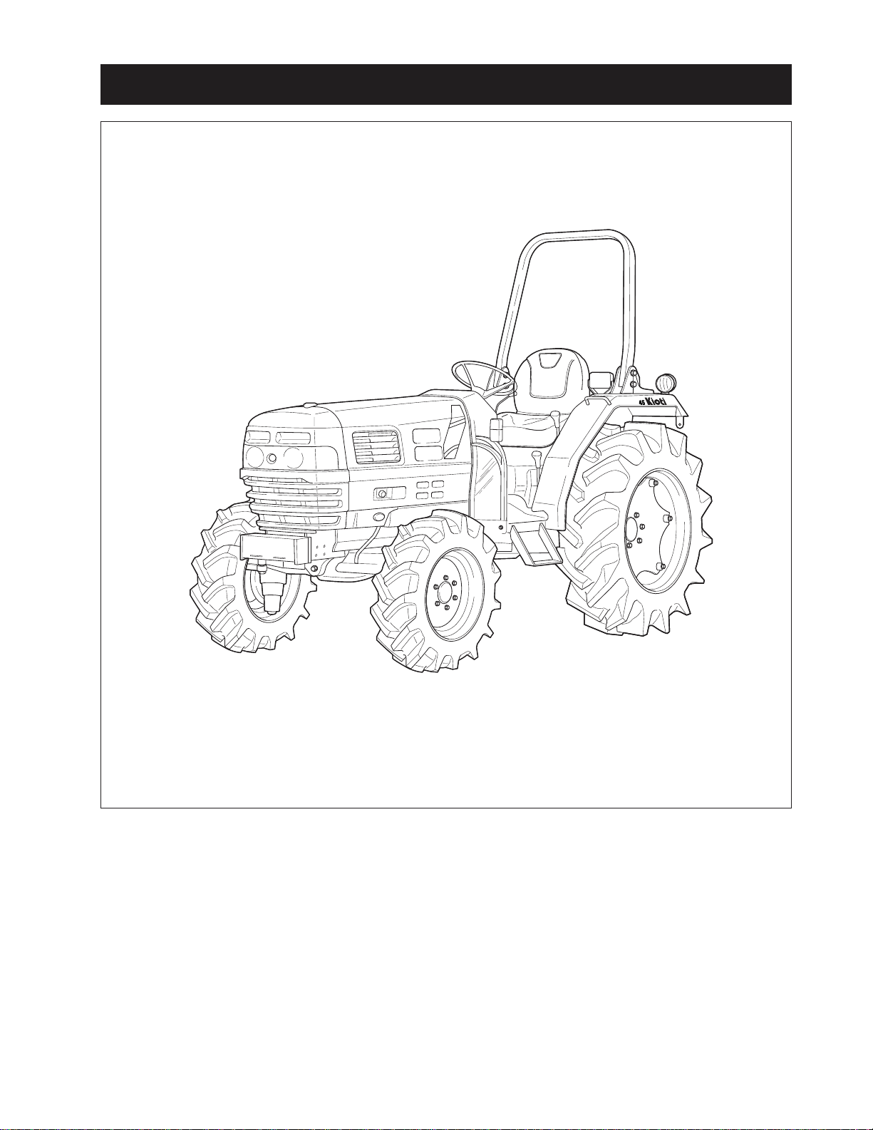
1. TRACTOR VIEW
GENERAL INFORMA TION
D569-W02 May-2003
569W101A
1-3
Page 12
CHAPTER 1 8454
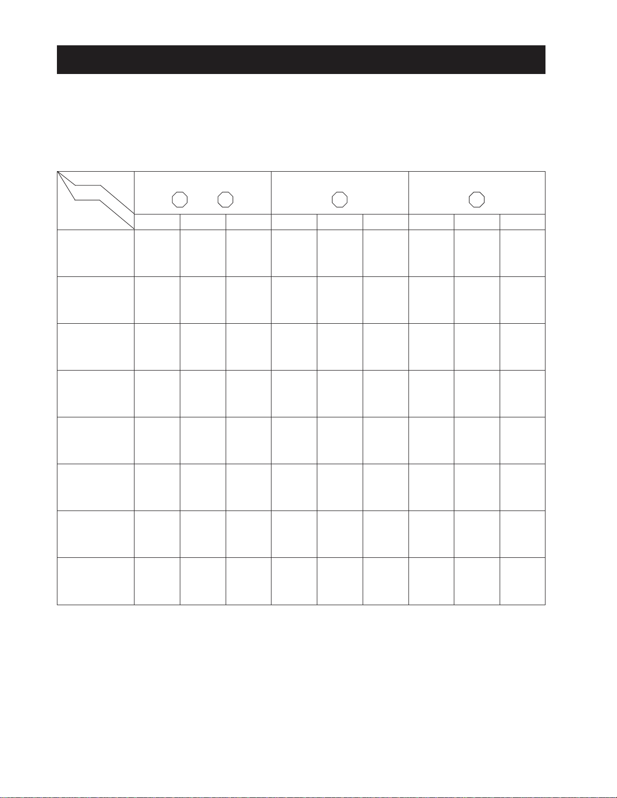
2. TIGHTENING TORQUE FOR STANDARD BOLTS AND NUTS
2.1 TIGHTENING TORQUE
Screws, bolts and nuts whose tightening torques are not specified in this workshop manual should be tightened
according to the table below.
A . TIGHTENING TORQUE FOR ST ANDARD BOLTS AND NUTS
Grade No grade 4T 7T 9T
Unit
Nominal
Diameter
M 6
(6 mm, 0.24 in.)
M 8
(8 mm, 0.31 in.)
M 10
(10 mm, 0.39 in.)
M 12
(12 mm, 0.47 in.)
M 14
(14 mm, 0.55 in.)
M 16
(16 mm, 0.63 in.)
M 18
(18 mm, 0.71 in.)
M 20
(20 mm, 0.79 in.)
N·m
7.85
~
9.30
17.7
~
20.5
39.2
~
45.0
62.8
~
72.5
108
~
125
167
~
191
245
~
284
334
~
392
Kgf·m
47 9
lbf·ft
9.1
~
10.5
21.7
~
25.3
44.9
~
52.1
76.0
~
86.8
123
~
144
192
~
224
254
~
297
362
~
420
0.80
~
0.95
1.8
~
2.1
4.0
~
4.6
6.4
~
7.4
11.0
~
12.8
17.0
~
19.5
25.0
~
29.0
34.0
~
40.0
lbf·ft
5.79
~
6.87
13.0
~
15.2
29.0
~
33.2
46.3
~
53.5
79.6
~
92.5
123
~
141
181
~
210
246
~
289
N·m
9.80
~
11.2
23.6
~
27.4
48.1
~
55.8
77.5
~
90.1
124
~
147
196
~
225
275
~
318
368
~
431
Kgf·m
1.00
~
1.15
2.4
~
2.8
4.9
~
5.7
7.9
~
9.2
12.6
~
15.0
20.0
~
23.0
28.0
~
32.5
37.5
~
44.0
lbf·ft
7.24
~
8.32
17.4
~
20.2
35.5
~
41.2
57.2
~
66.5
91.2
~
108
145
~
166
203
~
235
272
~
318
N·m
12.3
~
14.2
29.4
~
34.3
60.8
~
70.5
103
~
117
167
~
196
260
~
303
343
~
401
490
~
568
Kgf·m
1.25
~
1.45
3.0
~
3.5
6.2
~
7.2
10.5
~
12.0
17.0
~
20.2
26.5
~
31.0
35.0
~
41.0
50.0
~
58.0
* The figures on the table above are indicated the top of screw of bolt.
1-4
D569-W02 May-2003
Page 13

B. TIGHTENING TORQUE FOR STUDS
GENERAL INFORMA TION
M8
M10
M12
11.7 to 15.7 N·m
24.5 to 31.4 N·m
34.3 to 49.0 N·m
1.2 to 1.6 kgf·m
2.5 to 3.2 kgf·m
3.4 to 5.0 kgf·m
C. TIGHTENING TORQUE FOR HIGH PRESSURE HOSE UNION NUTS
Hose Size
(Inside Diameter: Inches)
Screw Size (PF)
Tightening (N·m)
Torque (kgf·m)
(lbf·ft)
1/8″ 3/16″ 1/4″ 5/16″ 3/8″ 1/2″ 5/8″, 3/4″ 1″
1/8″
9.8
1
7.2
1/4″
24.5
2.5
18.0
1/4″
24.5
2.5
18.0
3/8″
49.0
5
36.1
3/8″
49.0
5
36.1
8.6 to 11.5 lbf·ft
18.0 to 23.1 lbf·ft
25.3 to 36.1 lbf·ft
1/2″
58.8
6
43.3
3/4″
117.7
12
86.8
1″
137.3
14
101.2
D569-W02 May-2003
1-5
Page 14
CHAPTER 1 8454
MODEL
8454
38 HP
45 HP
4A220
Indirect injection, vertical, water-cooled,
4
87 x 92.4 (3.425 x 3.638in.)
2,197
2,600 RPM
18 before T.D.C.
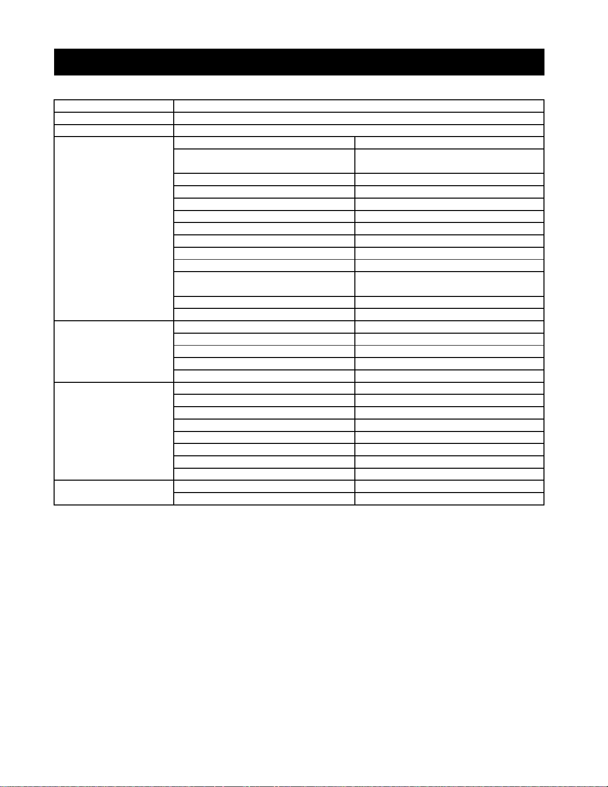
3. SPECIFICATION
Maximum PTO power
Engine GROSS power
Engine
Model
Capacities
Dimensions
(with std.tires)
Track width
Type
Number of cylinders
Bore and stroke
Total displacement
Rated revolution
Injection timing
Injection order 1-3-4-2
Compression ratio 22:01
Lubricating system Forced lubrication by trochoida pump
Cooling system
Alternator 12V, 50 AMPS
Weight (Dry) 207 kg (456lb)
Fuel tank 40 L (10.6 gal.)
Engine crankcase 7.0 L (1.9 gal.)
Engine coolant 8.9 L (2.4 gal.)
Transmission case 34.0 L (9.0 gal.)
Front axle case 8.2 L (2.2 gal.)
Overall length (without 3p) 3,073mm (120.9 in.)
Overall length (with 3p) 3,323mm (130.8 in.)
Overall Length (minimum tread) 1,550mm (61.0 in.)
Overall height (Top of ROPS) 2,235 mm (88.0 in.)
Overall height (Top of CABIN) 2,337 mm (92.0 in.)
Overall height (Top of steering wheel) 1,610 mm (63.3 in.)
Wheelbase 1,820 mm (71.6 in.)
Ground clearance 370 mm (14.5 in.)
Front 1,265 mm (49.8 in)
Rear
Pressurized radiator, Forced circulation
1,180 - 1,490mm (46.4 - 58.6 in.)
4cycle diesel
with water pump
1-6
Page 15
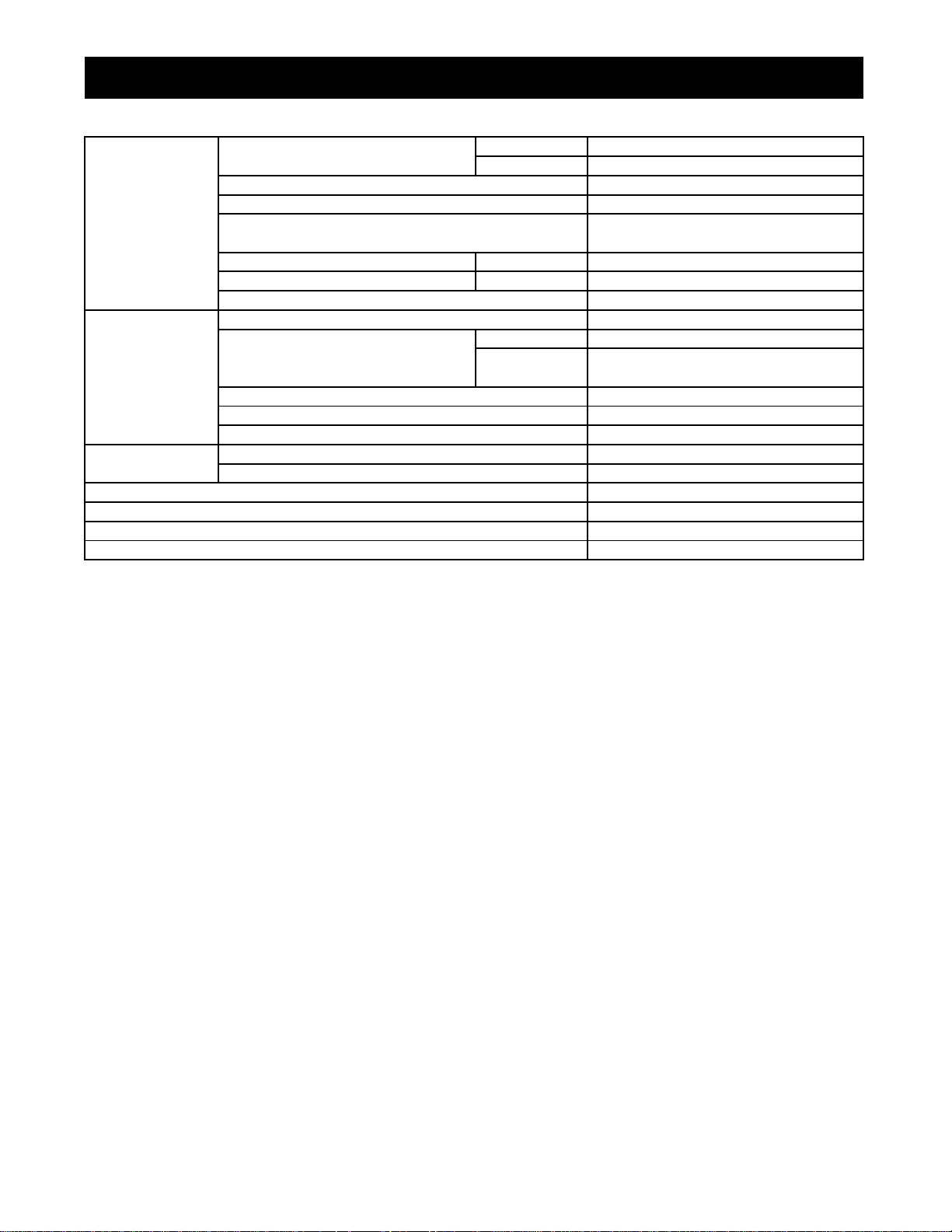
3. SPECIFICATION CON'T
Synchronized shuttle
Power steering
Maximum lifting capacity
Drive system
Hydraulic system
PTO
Min. turning radius ( without Brake)
Traction system
Weight (with ROPS)
Traveling speed ( at rated engine speed with Std tires)
Tire size (Std. Tires) Front 9.5 - 16.6
Rear 14.9 - 24.8
Clutch Dry single disc
Steering Hydrostatic steering system
Transmission
Brake Travel Wet disc type
Differential Bevel gear
Hydraulic lift control system Position, Draft and Mix control
Pump Capacity Main Pump 31.2 L/min (8.2 gal.)
Three point hitch SAE Category 1 & 2
No. of remote control valve ports (option) 2-4
PTO shaft SEA 1 3/8, 6 splines
Revolution (independent PTO) 560 rpm
12 forward and 12 reverse speeds
Parking Connected with the traveling brake
pump
Fixed drawer (or swing drawer Option)
0.37 - 24.6 km/h (0.23 - 15.29 mph)
18.7 L/min (5.0 gal.)
1,800 kg (3,968 lb)
2,865 mm (112.7 in.)
1,720 kg (3,792 lb)
1-7
Page 16
CHAPTER 1 8454
4. IDENTIFICATION
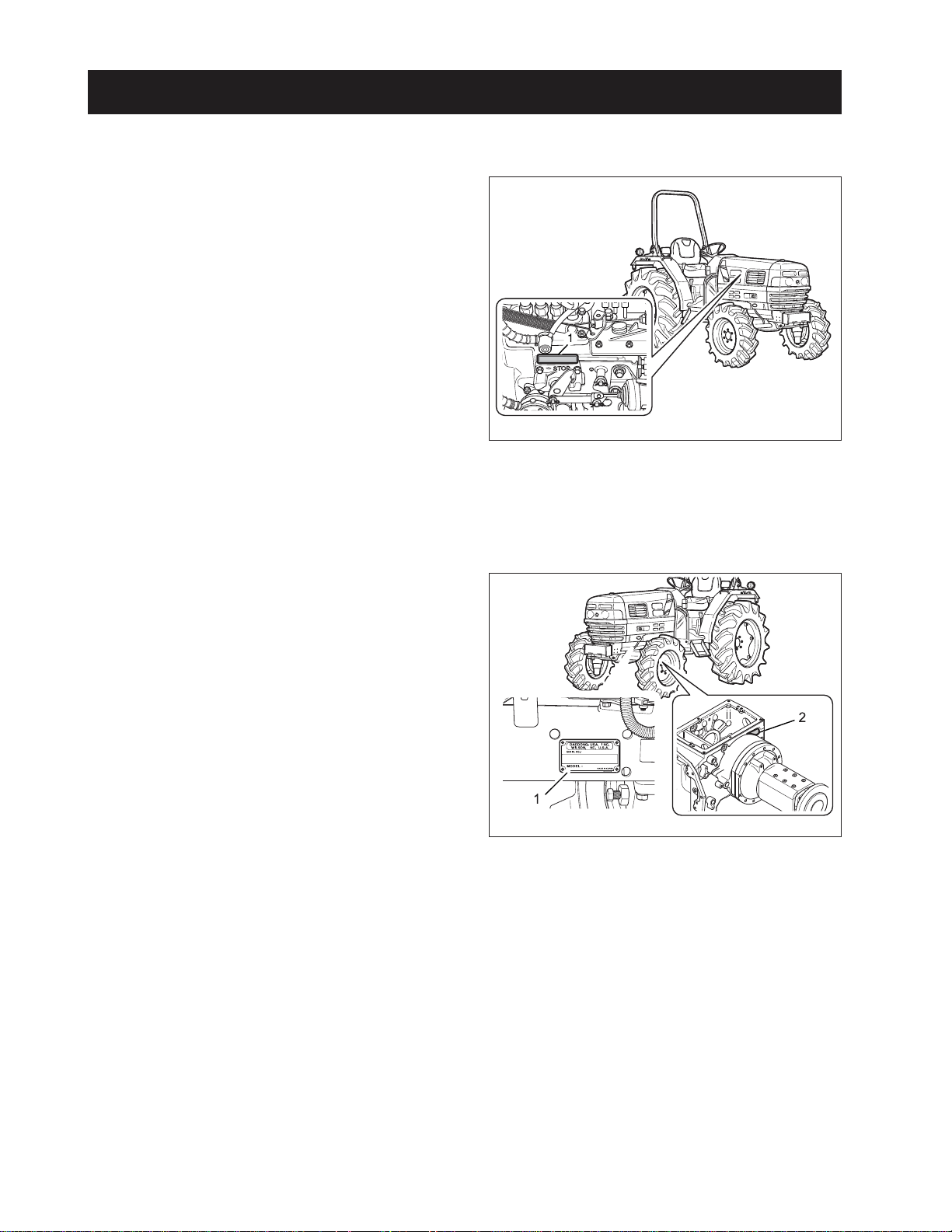
4.1 ENGINE NUMBER
Engine number is engraved in the left side of the cylinder block as shown in the figure.Engine number fills
the important role of providing it’s record.
569W103A
(1) Engine Serial Number
4.2 SERIAL NUMBER OF THE
TRACTOR
Serial number of the tractor is stamped on the left side
of the front axle frame as shown in the figure.
569W104A
(1) Tractor Serial Number
(2) Transmission Serial Number
1-8
D569-W02 May-2003
Page 17
5. CAUTION BEFORE REPAIR
C C
GENERAL INFORMATION
5.1 BEFORE REPAIR OR INSPECTION
1. In case of repair or inspection, locate the tractor
on the flat ground and pull the parking brake on.
2. Except for the items to be checked while the engine is running, be sure to stop the engine prior to
the work.
3. When washing parts, use parts washing solvent
for industrial use (avoid using gasoline so to prevent environmental pollution). For the hydraulic
parts, apply designated hydraulic oil in washing.
4. When disassembling and assembling of the hydraulic apparatus, pay special attention not to allow dust or foreign substance to be attached or
intermixed.
5.2 ASSEMBLY AND DISASSEMBLY
To check a failure, try to find out its underlying cause. If
assembly or disassembly is needed, perform the work
in regular sequence as specified in this repair manual.
7. Finish assembly within 20 minutes after applying
sealant, after that, wait approx. 30 minutes later
before filling with oil.
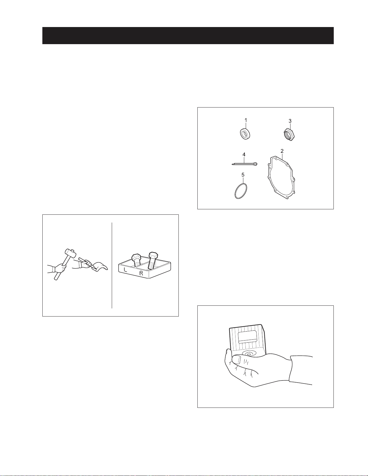
5.3 PARTS TO BE REPLACED
569W106A
The following parts should be replaced with new ones
when removed.
(1) Oil Seal
(2) Gasket
(3) Lock Nut
(4) Split Pin
(5) O-Ring
227W105A
1. Disassembled parts shall be arranged orderly.
2. Sort out the parts to be replaced from the ones to
be reused.
3. Be sure to use standard bolts and nuts that are
designated.
4. When assembling snap rings or spring pin types,
take care of assembling direction.
5. Split pin shall be spread surely not to escape when
installed.
6. When using sealant (such as gasket bond) on the
assembled surfaces, apply it evenly and consistently in a height of 3 ~ 5 mm (0.12 ~ 0.2 in.) on the
contact surface after removing the old bond and
cleaning the sealing surface with solvent. Apply
sealant on the center of the contact surface for the
space between the bolt holes of the contact
surface, and on the more inner side than the bolt
hole for the bolt area.
D569-W02 May-2003
5.4 PARTS
569W107A
When replacing part only genuine Cub Cadet parts.
1-9
Page 18
CHAPTER 1 8454
5.5 ASBESTOS PARTS
Since dust out of asbestos fibrous parts is extremely
dangerous to your health, be sure to clean such parts
carefully, do not use compressed air.
5.6 ELECTRICAL SYSTEM
1. Check electrical wiring every year for any damage
or short circuit at the connections. In addition, have
your dealer inspection the electric system regularly.
2. Do not modify or reorganize the wiring of the electric field parts.
3. When disconnecting the battery cable, disconnect
negative cable first, reinstall the positive cable first
when reinstalling.
Disconnect battery negative terminal
• Be sure to turn the starting key OFF
when connecting or disconnecting the
cable.
CAUTION
569W109A
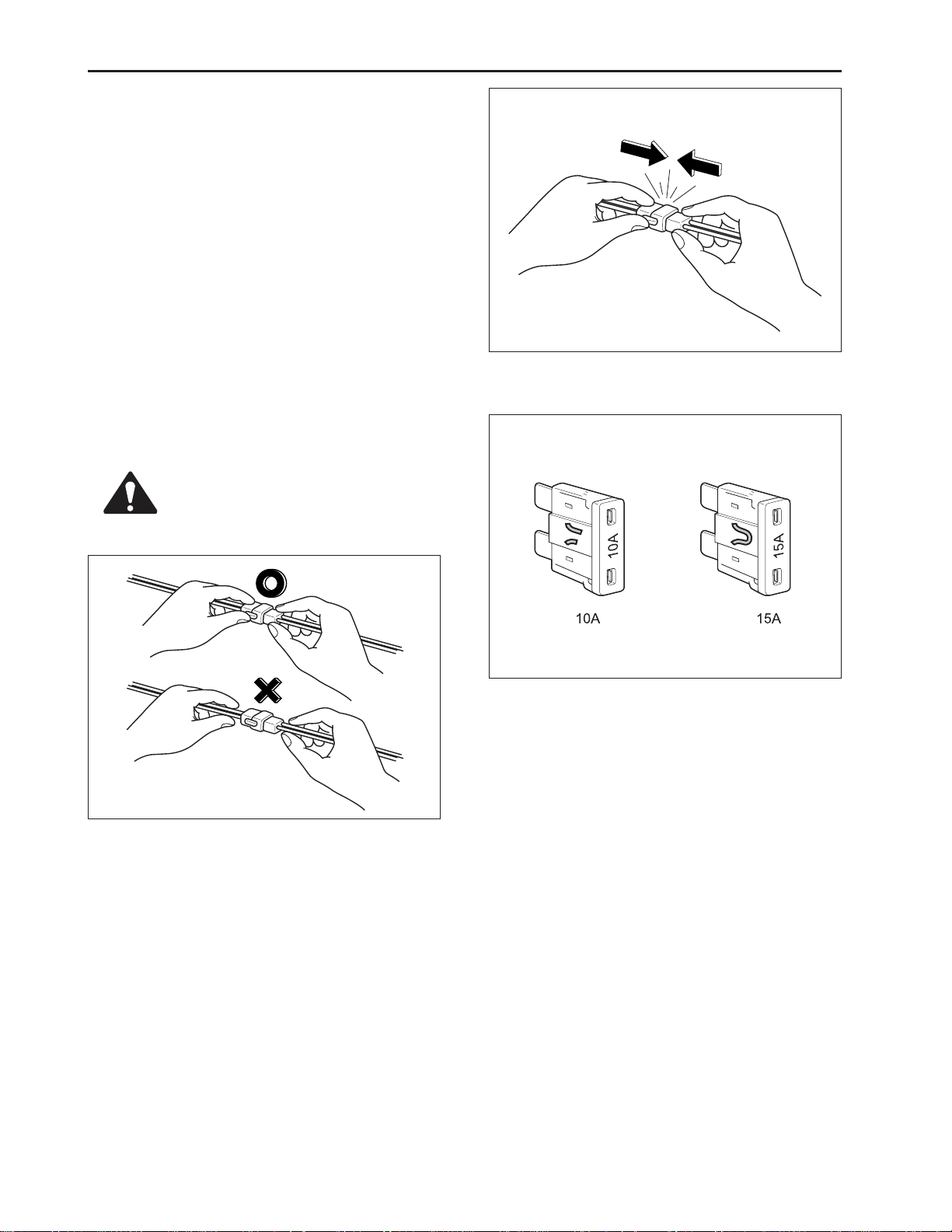
5. When connecting the connector, insert it until it
snaps.
569W108A
4. Remove the connector by pulling the plastic
section, not the wiring.
569W110 A
6. Be sure not to drop sensors and relays which are
fragile.
7. When replacing a broken fuse with a new one, be
sure to use the fuse of capacity as specified.
1-10
D569-W02 May-2003
Page 19
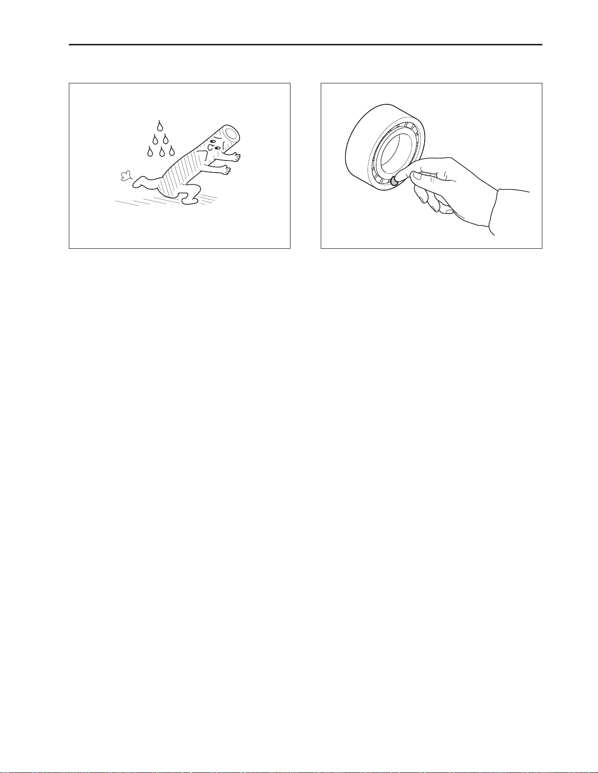
5.7 TUBES AND RUBBERS 5.8 LUBRICANT
GENERAL INFORMA TION
569W112 A569W11 1 A
Be cautious of oil or other petroleum products on the
hoses and rubber parts, this may cause damage.
When assembling and fixing, apply designated lubricant where specified in accordance with this repair
manual.
D569-W02 May-2003
1-11
Page 20
CHAPTER 1 8454
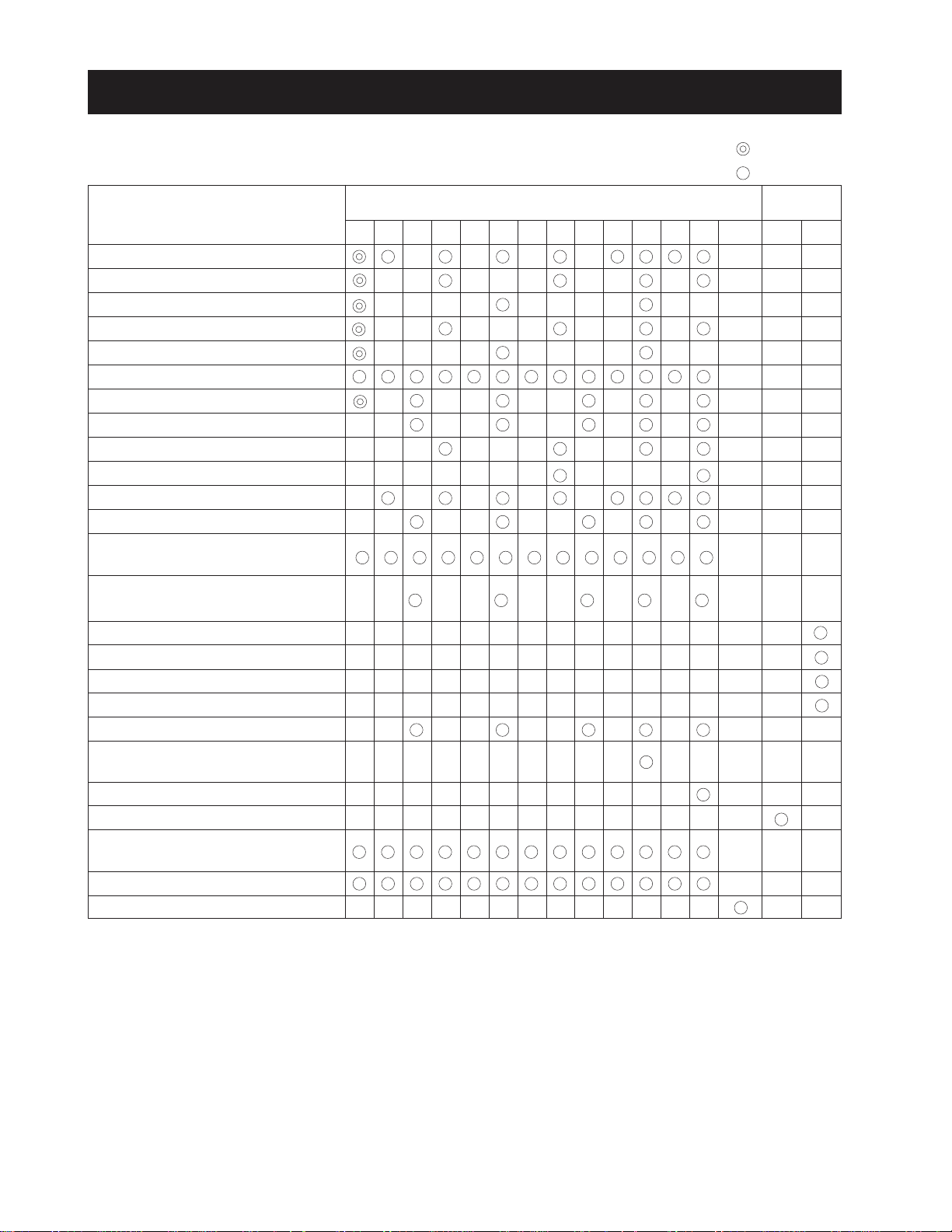
6. REGULAR CHECK LIST
Check Items
Engine oil change
Engine oil filter cartridge change
Transmission oil change
Hydraulic oil filter change
Front axle oil change
Applying grease
Clutch pedal deflection
Brake pedal deflection
Fan belt tension
Fuel filter element change
Air cleaner element change
Battery electrolyte
Oil pressure fuel pipe’s inlet screw
if loosened
Radiator hose’s inlet bands if
loosened
Fuel pipe change
Radiator hose change
Hydraulic pipe joint change
Steering hose change
Toe-in
Deflection adjustment in front and
rear of the front axle
Direction control section
Bolt, nuts and pins of each part
Battery positive code adjustment &
change
Bleeding water in clutch housing
Check injection nozzle*
Indicated Hours By Hour Meter
the first
periodically
Since
Purchased
80070060050045040035030025020015010050
1500hr
1yr 2yr
* Maintenance intervals in basis on the EPA instructions.
1-12
D569-W02 May-2003
Page 21
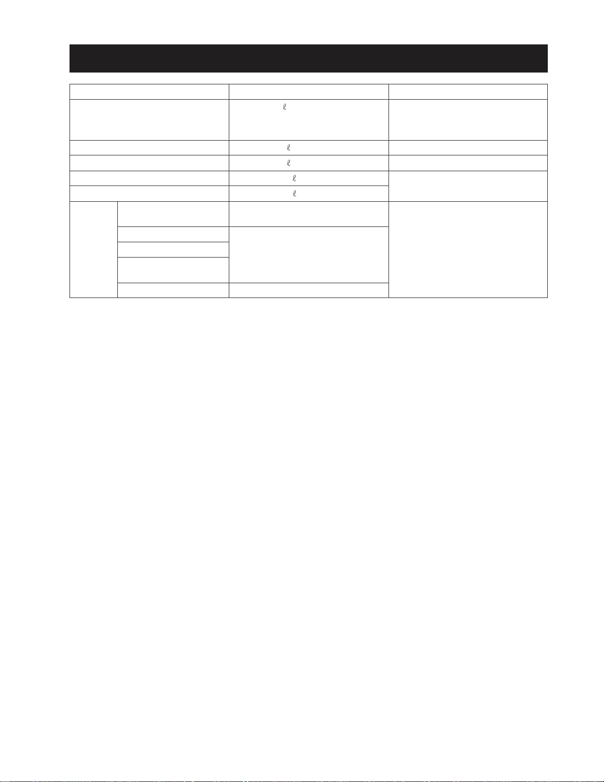
7. OIL & WATER SUPPLY LIST
GENERAL INFORMA TION
Supply Items
Fuel
Coolant
Engine oil
Transmission oil
Front axle section
Applying
grease
Hydraulic control lever
shaft section
3 point link section
Brake pedal link section
Bracket section in front
and rear of the front axle
Clutch release hub
Capacity
(42.3 U.S.gal.)
40
8.9
(2.4 U.S.gal.)
(1.8 U.S.gal.)
7.0
34
(9.0 U.S.gal.)
8.2
(2.2 U.S.gal.)
Small quantity
Until grease exits
Supply when removed
Recommended Spec.
No. 2 - D diesel fuel
No. 1 - D diesel fuel if temperature
is below - 10 °C (14 °F)
Fresh clean water with antifreeze
SAE 15 W - 40
Universal tractor/transmission
hydraulic oil
SAE multi-purpose type grease
D569-W02 May-2003
1-13
Page 22

Page 23

CHAPTER 2
ENGINE
Page 24

Page 25
1. GENERAL
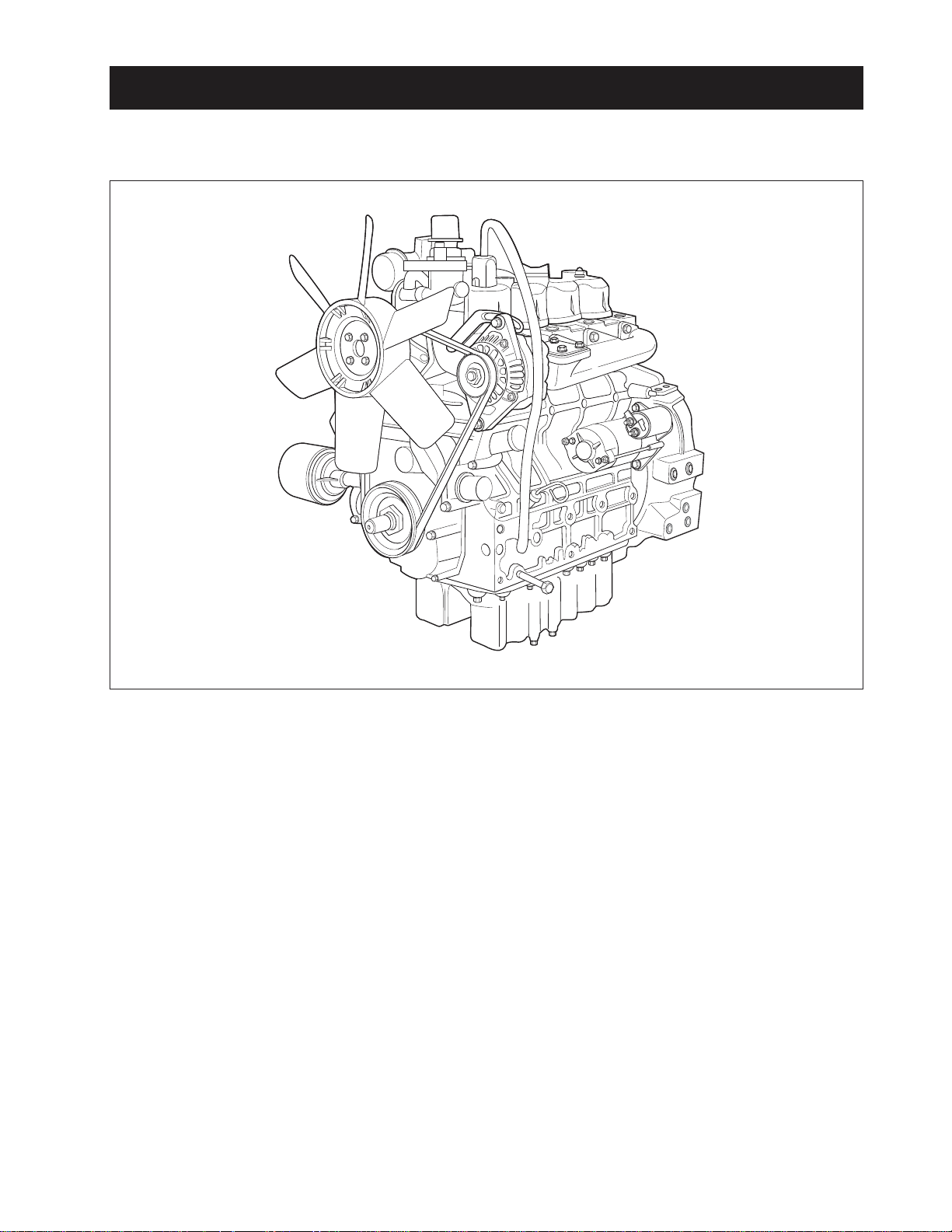
1.1 APPEARANCE
ENGINE
The DAEDONG A series engines are vertical, watercooled, 4-cycle, three or four cylinders diesel engines,
they concentrate DAEDONG’s foremost technologies.
With swirl combustion chamber, bosch K type fuel injection pump, well-balanced designs, they feature
greater power, low fuel consumption, less vibration and
noise, and low emission.
569W201A
D569-W02 May-2003
2-3
Page 26

CHAPTER 2 8454
1.2 SPECIFICATIONS
MODEL
Type
Number of cylinder
Bore and stroke mm (in.)
3
Total displacement cc (in
.)
Combustion chamber
POWER (NET) PS/rpm (kW. rpm)
Maximum idling speed rpm
Minimum idling speed rpm
Order of firing
Direction of rotation
Injection pump
Injection pressure
Injection timing (Before T.D.C)
Compression ratio
Fuel
Lubricant
Dimensions mm
(length x width x height) (in.)
Dry weight kg (kg, lbs.)
4A220
Vertical, water-cooled,
4-cycle diesel engine
4
87.0 x 92.4 (3.43 x 3.64)
2,197(134.1
)
vortex chamber
43/2,700 (30.9/2,700)
2,900
850 ~ 900
1-3-4-2
Counterclockwise
(viewed from flywheel side)
Bosch K TYPE mini pump
140 ~ 150 kgf/cm
2
(13.73 ~ 14.71 MPa, 1991 ~ 2133 psi)
18°
22 : 1
Diesel fuel
Engine oil SAE 15W-40
817.3 x 488.1 x 735.8
(32.2 x 19.2 x 29.0)
207 (456)
4A200T
Vertical, water-cooled,
4-cycle diesel engine (Turbo)
4
83.0 x 92.4 (3.27 x 3.64)
1,999(122.0)
vortex chamber
47/2,600 (34.6/2,600)
2,800
850 ~ 900
1-3-4-2
Counterclockwise
(viewed from flywheel side)
Bosch K TYPE mini pump
140 ~ 150 kgf/cm
2
(13.73 ~ 14.71 MPa, 1991 ~ 2134 psi)
12°
22 : 1
Diesel fuel
Engine oil SAE 15W-40
817.3 x 542.0 x 735.8
(32.2 x 19.2 x 29.0)
211 (465)
* NOTE: Change of parts are not subject to advance notice.
2-4
D569-W02 May-2003
Page 27
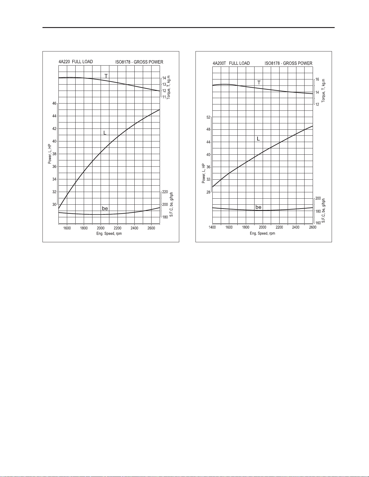
1.3 PERFORMANCE CURVE
ENGINE
569W204A 569W203A
D569-W02 May-2003
2-5
Page 28
CHAPTER 2 8454
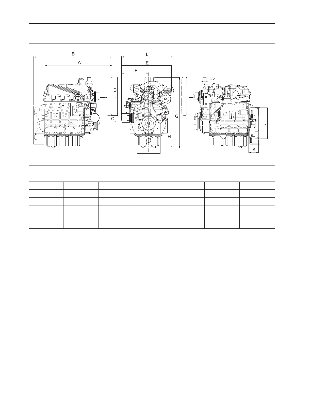
1.4 DIMENSIONS
569W205A
Sample/td Spec.
4A220
4A200T
4A220
4A200T
A
697.3 (27.45)
697.3 (27.45)
G
736 (28.98)
736 (28.98)
B
817.3 (32.18)
817.3 (32.18)
H
260 (10.24)
260 (10.24)
280 (11.02)
280 (11.02)
240 (9.45)
240 (9.45)
1.5 GENERAL WARNING
• When disassembling, arrange each part on a clean
place. Do not mix them up. Replace bolts and nuts
where they were.
• When connecting instruments to electrical
equipment, first disconnect battery negative
terminal.
• Replace gaskets or O-rings with new ones when
reassembling, and apply grease on a O-rings and
the oil seals when reassembling.
• When exchanging parts, use genuine DAEDONG
parts to maintain engine performance and safety.
• To prevent oil and water leakage, apply non-drying
adhesive to the gaskets according to this manual
before reassembling.
• When hoisting up the engine, use the hook provided on the cylinder head.
• When installing the engine, use the hook provided
on the cylinder head.
• When installing external cir-clips or internal cir-clips,
direct corner end to the non- loosening direction.
mm (in.)
C
I
D
φ
400 (15.75)
φ
400 (15.75)
J
φ
321 (12.64)
φ
321 (12.64)
E
502.6 (19.79)
519 (20.43)
K
104.5 (4.11)
104 (4.09)
F
262.5 (10.33)
282.4 (11.12)
L
-
542 (21.34)
2-6
D569-W02 May-2003
Page 29
2. STRUCTURE AND FUNCTION
2.1 BODY
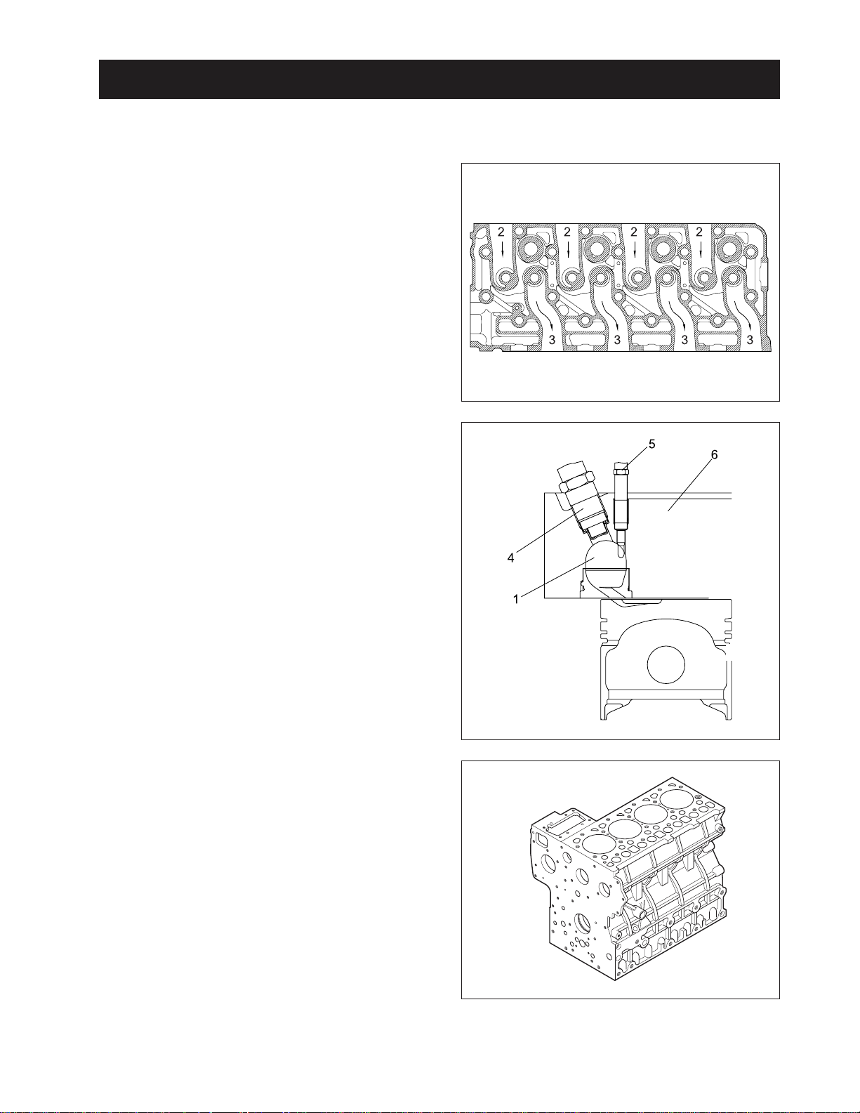
A . CYLINDER HEAD
The cylinder head is made of special alloy cast iron
which can resist high temperature and pressure
caused by combustion. The intake and exhaust ports
are arranged cross-flow type to get high combustion
efficiency by protecting the suction air from being heated
and expanded by heated exhaust air.
The Daedong vortex type combustion chamber is designed for high efficiency combustion and reducing fuel
consumption. The glow plugs assures easy engine
starts even at (-) 15 °C (5 °F).
(1) Combustion Chamber
(2) Inlet Port
(3) Exhaust Port
(4) Injection Nozzle
(5) Glow Plug
(6) Cylinder Head
ENGINE
569W206A
B. CYLINDER BLOCK
The engine has a high durability tunnel-type cylinder
block. Furthermore, liner less type, allows effective cooling, less distortion, and greater wear-resistance using
special material. The noise is reduced to a minimum
because each cylinder had its chamber.
D569-W02 May-2003
569W207A
569W208A
2-7
Page 30
CHAPTER 2 8454
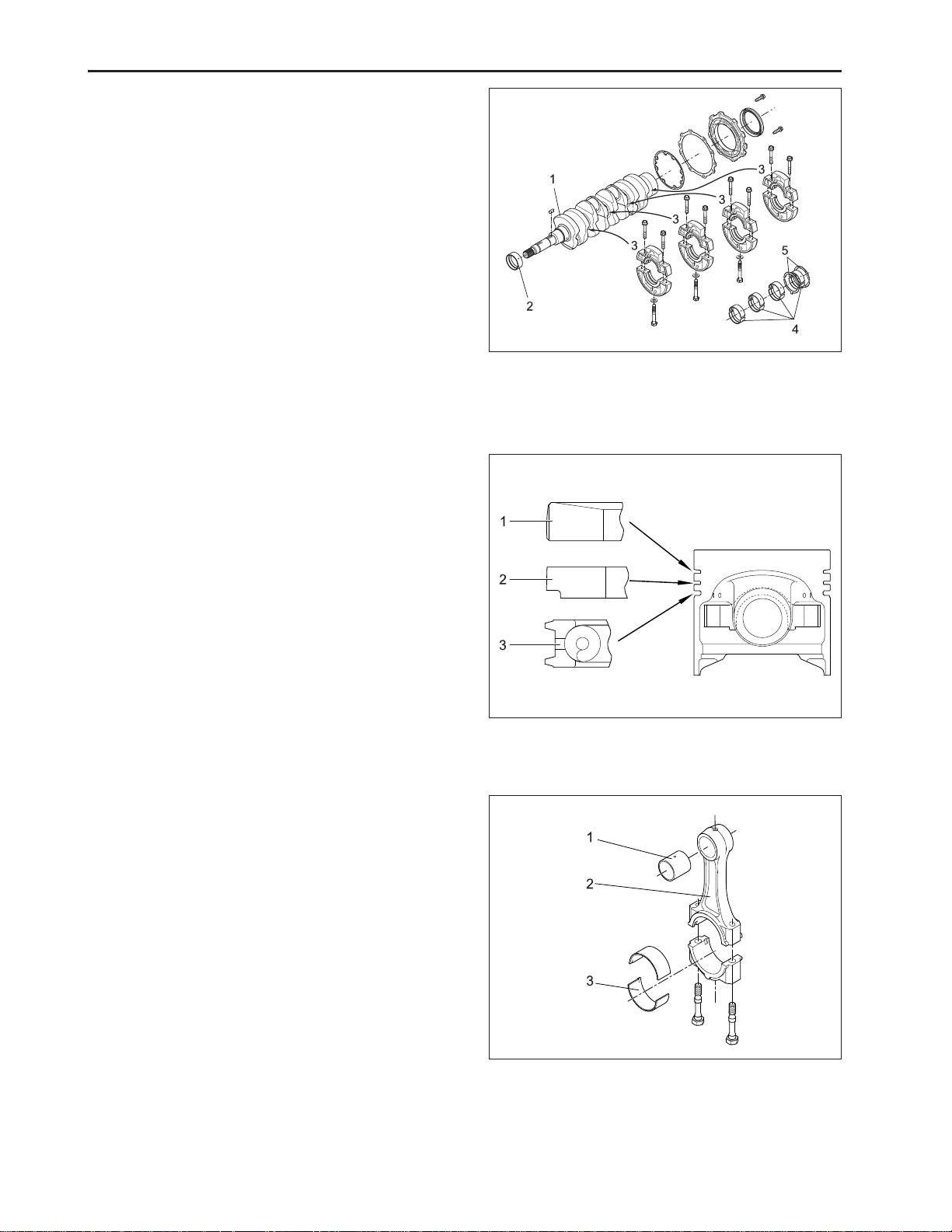
C. CRANKSHAFT
The crankshaft is made of forged steel and the journals,
the crankpins and the bearing surface for the oil seal
are induction-hardened to increase wear resistance.
Each crankshaft journal is supported by the main bearing case (3) having a bearing inside.
The front crankshaft bearing (2) is a solid type bushing
and rear and intermediate bearings are a split type.
The crankshaft’s bearings have oil holes for lubricant
flow.
D. PISTON AND PISTON RINGS
The piston are made of an aluminum alloy which is
temperature and pressure resistant. Three rings installed in grooves of the piston. The top ring (1) is a
keystone type, which can withstand heavy loads, and
the barrel face on the ring fits well to the cylinder wall.
The second ring (2) is an undercut type, which prevents the oil from being carried up. The oil ring (3) has
chambered contact faces and an expander ring, which
increase the pressure of the oil ring against the cylinder wall to scrape the oil. The top ring is plated with
hard chrome to increase wear resistance (The ring of
4A200T engine is mode of a special steel).
569W209A
(1) Crankshaft (4) Crankshaft Bearing 2
(2) Crankshaft Bearing (5) Thrust Bearing
(3) Main Bearing Case
E. CONNECTING ROD
The connecting rod (2), which converts the reciprocating motion of the pistons caused by the fuel combustion into the rotating motion of the crankshaft, is made
of harden forged steel. The connecting rod has bearings at both ends. The small end has a solid type bearing (small end bushing (2)) and the big end has a split
type bearing (crankpin bearing (3)).
569W210A
(1) Top Ring (3) Oil Ring
(2) Second Ring
569W211A
(1) Small End Bushing (3) Crankpin Bearing
(2) Connecting Rod
2-8
D569-W02 May-2003
Page 31

F. CAMSHAFT
The camshaft (3) is made of forged steel and it’s journals and cams are hardened to increase wear
resistance. The cams on the camshaft open and close
the intake and exhaust valves with the push rods and
rocker arms. The journals and their bearings are forcelubricated.
G. FUEL CAMSHAFT
This fuel camshaft is made of forged steel and its cams
are hardened and tempered to increase wear
resistance. The cams on the fuel camshaft (1) drive
the injection pump and the fuel transfer pump. The
governor balls are installed on the fuel camshaft to
control the engine speed.
ENGINE
569W212A
(1) Cam Gear (3) Camshaft
(2) Camshaft Stopper
H. ROCKER ARM ASSEMBL Y
The rocker arm assembly includes the rocker arms (1)
and an adjusting screw (3), which is at the end of rocker
arm and rests on the push rod, rocker arm brackets (4)
and rocker arm shaft (5). The rocker arms are activated
by the reciprocating motion of the push rods and open
or close the intake and exhaust valves. The rocker arm
and other parts are lubricated through the drilled holes
of the brackets and the rocker arm shaft.
569W213A
(1) Fuel Camshaft (2) Injection Pump Gear
569W214A
(1) Rocker Arm (4) Rocker Arm Bracket
(2) Lock Nut ( 5 ) Rocker Arm Shaft
(3) Adjusting Screw
D569-W02 May-2003
2-9
Page 32

CHAPTER 2 8454
I. INTAKE AND EXHAUST VAL VES
The valve and its guide of the intake are different from
those for the exhaust. Other parts, such as the spring,
spring retainers, valve spring collets, valve stem seals
are the same for both the intake and the exhaust. All
contact or sliding surfaces are hardened to increase
wear resistance.
J. TIMING GEARS
The crankshaft drives the oil pump and the idle gear
engaged fuel camshaft and camshaft. The timing for
opening and closing the valves is extremely important
to achieve effective air intake and sufficient gas exhaust.
The appropriate timing can be obtained by aligning the
mark on the crankshaft gear (6) with one the idle gear
(5), idle gear with camshaft gear, idle gear with injection pump gear, when assembling.
569W215A
(1) Valve Spring Collet (4) Valve Stem Seal
(2) Valve Spring Retainer ( 5) Exhaust Valve
(3) Valve Spring (6) Intake Valve
K. FLYWHEEL
The flywheel is installed on the rear end of the
crankshaft. Its inertia keeps the engine turning at a
constant speed, while the crankshaft tends to speed
up during the power stroke and to slow down during
other stokes. The flywheel has a ring gear (1), which
meshes with the drive pinion of the starter.
The flywheel has marks “TC” and “FI” on its outer rim.
The mark TC shows the piston’s top dead center and
the mark FI shows the fuel injection timing, when they
are aligned with the mark of window on the clutch housing.
569W216A
(1) Injection Pump Gear (5) Idle Gear
(2) Fuel Camshaft (6) Crankshaft Gear
(3) Camshaft Gear (7) Crankshaft
(4) Camshaft
569W217A
(1) Ring Gear (3) Crankshaft
(2) Flywheel
2-10
D569-W02 May-2003
Page 33

2.2 LUBRICATING SYSTEM
A . FLOW OF LUBRICATING OIL
The lubricating oil is forced to each journal through the
oil passages of the cylinder block, cylinder head and
shafts. The oil, splashed by the crankshaft or thrown
off from the bearings, lubricates other engine parts
such as the push rods (11), tappets (12), piston pins
and timing gears.
ENGINE
B. OIL PUMP
The oil pump is a gear type. Whose rotors have trochoid lobes. The inner rotor (3) has 4 lobes and the
outer rotor (4) has 5 lobes, and they are eccentrically
engaged to each other. The inner rotor, which is driven
by the crankshaft through the gears, rotates the outer
rotor in the same direction, varying the space between
the lobes.
While the rotors rotate from (A) to (B), the space leading to the inlet port increases, which causes the oil to
flow through the inlet port. When the rotors rotate to
(C), the port to which the space leads is changed from
inlet to outlet. At (D), the space decreases and oil is
discharged though the outlet port.
569W218A
(1) Piston (9) Rocker Arm Shaft
(2) Idle Gear (10) Rocker Arm
(3) Oil Pump (11) Push Rod
(4) Relief Valve (12) Tappet
(5) Strainer (13) Oil Pressure Switch
(6) Oil Filter Element (14) Camshaft
(7) Bypass Valve (15) Crankshaft
(8) Oil Pan
569W219A
D569-W02 May-2003
(1) Inlet (3) Inner Rotor
(2) Outlet (4) Outer Rotor
2-11
Page 34

CHAPTER 2 8454
C. OIL FIL TER AND RELIEF V ALVE
The lubricating oil force-fed by the pump is filtered by
the filter cartridge, passing through the filter element
from the outside to the inside. When the filter element
accumulates dirt and the pressure difference between
the inside and the outside rises more than 98 kPa
(1.0 kgf/cm
allow the oil to flow from the inlet line to outlet line,
bypassing the filter element. The relief valve ball (4) in
the inlet line allows oil to prevent damage to the lubricating system, when the oil pressure rises more than
441 kPa (4.5 kgf/cm
2
, 14 psi), the bypass valve (1) opens to
2
, 64 psi).
569W220A
(1) Bypass Valve
(2) Bypass Adjusting Spring
(3) Filter Element
(4) Relief Valve Ball
(5) Relief Adjusting Spring
(a) To Idle Gear, Camshaft and Rocker Arm
(b) From Oil Pump
(c) To Crankshaft Journal Crankpin
(d) Drain of Relief Valve
D. OIL PRESSURE SWITCH
The oil pressure switch is installed on the cylinder
block and leads to the oil passage of the lubricating
oil. When the oil pressure falls below the specified
value, the contacts of the oil pressure switch closes to
turn on the warning lamp (1).
569W221A
(A) At lower Oil Pressure
(49 kPa (0.5 kgf/cm
2
, 7 psi) or less)
(B) At Proper Oil Pressure
(1) Warning Lamp (6) Rubber washer
(2 ) Battery (7 ) Oil Pressure
(3) Contact Movable (8) Cylinder Block
(4) Contact Cup (9) Pressure
(5) Diaphragm
2-12
D569-W02 May-2003
Page 35

2.3 COOLING SYSTEM
A. FLOW OF COOLING WA TER
The cooling system consists of a radiator (5), a centrifugal water pump (7), a cooling fan (6) and a thermostat (2). The water is cooled as it flows through the
radiator core, and the fan behind the radiator pulls the
cooling air through the radiator core. The water pump
receives water from the radiator or from the cylinder
head and forces it into cylinder block. The thermostat
open or closes according to the water temperature.
When the water temperature is high, the thermostat
opens to allow the water to flow from the cylinder block
to the radiator. When the water temperature is low, the
thermostat closes and the flow stays within the block.
The opening temperature of the thermostat is approx.
70 °C (160 °F).
ENGINE
569W222A
(1) Water Return Pipe
(2) Thermostat
(3) Cylinder Head Water Jacket
(4) Cylinder Block Water Jacket
(5) Radiator
(6) Cooling Fan
(7) Water Pump
B. WA TER PUMP
The water pump is driven with the fan drive pulley, which
is on the water pump shaft and driven by the crankshaft
with a belt. The water pump sucks the cooled water,
forces into the cylinder block and draws out the hot
water to the radiator repeatedly. The mechanical seal
(3) prevents the water from entering the bearing (1).
569W223A
(a) From the Thermostat
(b) To the Cylinder Block
(c) From the Radiator
D569-W02 May-2003
(1) Bearing (3) Mechanical Seal
(2) Pump Body (4) Pump Impeller
2-13
Page 36

CHAPTER 2 8454
C. THERMOSTAT
The thermostat is wax pellet type, which controls the
flow of the cooling water to the radiator to keep the
proper temperature. The case has a seat (1) and the
pellet has a valve (2). The spindle attached to the case
is inserted into the synthetic rubber in the pellet. The
pellet is charged with wax.
(A) At low temperature (lower than 71 °C (160 °F)). The
valve (2) is seated by the spring (7) and the cooling
water circulates in the engine through the water return
pipe but does not enter the radiator.
(B) At high temperature (higher than 71 °C (160° F)). As
the water temperature rises, the wax in the pellet (3)
turns liquid and expands, repelling the spindle. The
pellet lowers and the valve (2) opens to send the cooling water to the radiator.
569W224A
(1) Seat (6) Wax (Solid)
(2) Valve (7) Spring
(3) Pellet ( 8) Leak Hole
(4) Spindle (9) Wax (Liquid)
(5) Synthetic Rubber
D. RADIATOR
The radiator core consists of water carrying tubes (2)
with fins (3) at a right angle to it. The water in the radiator is cooled by the air flowing through between the
tube wall and the fin.
E. RADIAT OR CAP
The pressure type cap is installed on the radiator, which
prevents the pressure difference between the inside
and the outside of the radiator from deforming the radiator.
(A) At high pressure
2
Higher than 88 kPa (0.9 kgf/cm
ant temperature rises and the pressure in the radiator
increase above the specified pressure, the pressure
valve (1) opens to reduce the internal pressure.
(B) At low pressure
When the coolant temperature falls and a vacuum is
formed in the radiator, the vacuum valve (2) opens to
allow coolant stored in the over flow tank to enter the
radiator.
, 13 psi) when the cool-
569W225A
(1) Cooling Air (3 ) Fi n
(2) Tube
569W226A
(1) Pressure Valve (2) Vacuum Valve
2-14
D569-W02 May-2003
Page 37

2.4 FUEL SYSTEM
A. FLOW OF FUEL
The fuel is fed from the fuel tank (1) through the fuel
feed pump (7) to the injection pump (3) thru the fuel
filter (2). The injection pump force-feds the fuel through
the injection nozzles (5), which inject the fuel into the
cylinders for combustion. The excessive fuel from the
injection pump to the injection nozzles is collected in
the fuel overflow pipes (6) and returns to the fuel tank.
ENGINE
569W227A
(1) Fuel Tank (5) Injection Nozzle
(2) Fuel Filter ( 6) Fuel Overflow Pipe
(3) Injection Pump ( 7) Fuel Feed Pump
(4) Injection Pipe
B. FUEL FILTER
The fuel filter removes dirt and water with its fine filter
paper, which collects particles of 90 microns (0.0034
in.) at 20 kPa (0.2 kgf/cm
feed pump is filtered by the filter element (6), while
flowing through the filter body (3). The air vent (2) returns the air in the fuel to the fuel tank to prevent the
engine from stopping or running irregularly.
2
, 3 psi). The fuel from the fuel
569W228A
(a) To Fuel Tank
(b) From Fuel Feed Pump
(c) To Injection Pump
(1) Cock (4) Retainer Ring
(2) Ai r V e n t (5) Pot
(3) Filter Body (6) Filter Element
D569-W02 May-2003
2-15
Page 38
CHAPTER 2 8454
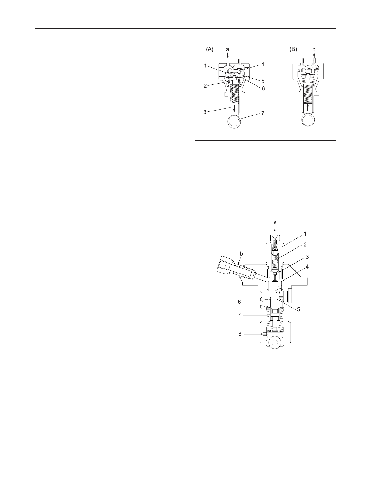
C. FUEL FEED PUMP
The diaphragm (6) is linked to the tappet (3) with a
push rod (2). The tappet is reciprocated by the eccentric cam on the fuel camshaft (7).
(A) Inlet stroke
When the diaphragm is pulled down by the spring,
vacuum in the chamber (5) causes the outlet valve (4)
to close and the atmospheric pressure in the fuel tank
forces the fuel into the chamber, opening the inlet valve
(1).
(B) Discharge stroke
When the diaphragm is pushed up by the cam, the
pressure in the chamber causes the inlet valve to close
and forces out the fuel, opening the outlet valve.
569W229A
(a) From Fuel Tank
(b) To Fuel Filter
(1) Inlet Valve (5) Chamber
(2) Push Rod (6) Diaphragm
(3) Tappet (7) Fuel Camshaft
(4) Outlet Valve
D. FUEL INJECTION PUMP
The injection pump is bosch K type mini injection
pump. It features a compact and light weight design.
569W230A
(a) To Injection Nozzle
(b) From Fuel Filter
(1) Delivery Valve Holder (5 ) Plunger
(2) Delivery Valve Spring (6) Control Rack
(3) Delivery Valve (7) Plunger Spring
(4) Cylinder (8) Tappet
2-16
D569-W02 May-2003
Page 39

a. Pump Element
The pump element (1) consists of a plunger (3) and
cylinder (2), their sliding surfaces are precision machined to maintain fuel tightness. The plunger (3) fits
in the control sleeve (5) at the driving surface (7). The
sleeve is engaged with the control rack, which rotate
the plunger in the cylinder to control the amount of fuel
delivery.
ENGINE
569W231A
b. Operation of Pump Element
(A) Before delivery
As the taper lowers, the plunger (2) lowers and fuel is
drawn into the delivery chamber (1) through the feed
hole (4) from the fuel chamber (5).
(B) Beginning of delivery
When the plunger is pushed up by the cam and the
head of the plunger closes the feed hole (4), the pressure in the delivery chamber (1) rises to push the delivery valve (3) open.
(C) Delivery
While the plunger (2) is rising, delivery of fuel continues.
(D) End of delivery
When the plunger rises further and the control groove
(6) on its periphery meets the feed hole, the fuel returns to the fuel chamber (5) from the delivery chamber
(1) through the control groove (6) and the feed hole (4).
(1) Pump Element (5) Control Sleeve
(2) Cylinder (6) Control Groove
(3) Plunger (7) Driving Surface
(4) Feed Hole
D569-W02 May-2003
569W232A
(1) Delivery Chamber (4) Feed Hole
(2) Plunger (5) Fuel Chamber
(3) Delivery Valve (6) Control Groove
2-17
Page 40

CHAPTER 2 8454
c. Amount of Fuel Delivery
(A) No fuel delivery
At the engine stop position of the control rack (3), the
lengthwise slot (1) on the plunger (2) aligns with the
feed hole (5). The delivery chamber (4) is led to the
feed hole during the entire stroke of the plunger. The
pressure in the delivery chamber does not build up
and no fuel is forced to the injection nozzle.
(B) Fuel delivery
The plunger is rotated by the control rack and the feed
hole is not aligned with the lengthwise slot. When the
plunger is pushed up, the feed hole is closed by the
plunger. The pressure in the delivery chamber builds
up and forces the fuel to the injection nozzle until the
control groove (6) meets the feed hole. The amount of
the fuel to be forced into the nozzle corresponds to
distance A.
569W233A
d. Delivery Valve
The delivery valve prevents the fuel in the injection pipe
from flowing back into the delivery chamber and the
fuel in the injection nozzle from dribbling after injection.
(1) Slot (4) Delivery Chamber
(2) Plunger (5) Feed Hole
(3) Control Rack ( 6) Control Groove
2-18
569W234A
(1) Valve Spring (4) Fuel Chamber
(2) Valve (5) Valve Face
(3) Valve Seal (6) Relief Plunger
D569-W02 May-2003
Page 41

E. FUEL INJECTION NOZZLE
The nozzle is a throttle-type. It features low fuel consumption and works well with DAEDONG combustion
chamber. The nozzle valve opening pressure is about
13.7 to 14.7 MPa (140 to 150 kgf/cm
psi), the pressure overcomes the counterforce of nozzle
valve spring, and push the valve up instantly, the fuel is
then injected in a proper quantity into the swirling air in
the combustion chamber for combustion. Addition or
reduction of adjusting shims can adjust the opening
pressure. A washer of 0.1 mm corresponds to 980 kPa
(10 kgf/cm
2
, 142 psi) change in opening pressure. The
heat seal is employed to improve the durability and
reliability of the nozzle.
2
, 1,991 to 2,134
ENGINE
569W235A
F. GOVERNOR AND IDLE COMPENSATING
a. Disassembled View
The governor serves to keep engine speed constant by
automatically adjusting the amount of fuel supplied to
the engine according to changes in the load. The engine employs an all-speed governor which is controlled
by the centrifugal force of the steel ball (13) weights,
produced by rotation of the fuel camshaft (9), and tension of the governor spring 1 (2) and 2 (3) are balanced.
(1) Nozzle Holder Ass’y (6) Nozzle Body
(2) Adjusting Washer (7) Needle Valve
(3) Nozzle Spring (8) Heat Seal
(4) Push Rod (9) Packing
(5) Retaining Nut
569W236A
D569-W02 May-2003
(1) Start Spring (8) Governor Lever
(2) Governor Spring 1 (9 ) Fuel Camshaft
(3) Governor Spring 2 (10) Governor Ball Case
(4) Fork Lever 1 (11) Steel Ball
(5) Fork Lever 2 (12) Governor Sleeve
(6) Fork Lever Shaft (13) Steel Ball
(7) Fork Lever Holder
2-19
Page 42

CHAPTER 2 8454
b. Operation of Governor
a) At start
The steel balls (13) have no centrifugal force. As the
fork lever 1 (4) is pulled by the start spring (1), the
control rack (14) moves to the maximum injection position. At start, the sufficient injection of the fuel enables
easy starting.
b) At idling
At the idling position of the speed control lever (15), the
governor spring 1 (2) is free and the governor spring 2
(3) only acts slightly. The governor sleeve (12) is
pushed leftward by a centrifugal force of steel ball (13).
Therefore, the fork lever 1 (4) and control rack (14) are
moved to the rear by the governor sleeve (12) and then
the idling adjusting spring (16) is compressed by the
control rack (14). As a result, the control rack (14) is
kept at a position where the centrifugal force of steel
ball (13) and forces of the start spring (1), governor
spring 2 (3) and idling limit spring are balanced, providing stable idling.
569W237A
(1) Start Spring (13) Steel Ball
(4) Fork Lever 1 (14) Control Rack
IMPORTANT:
• The idling speed has been factory-set. The idling
adjusting screw (20) and spring (16) should not be
disassembled and readjusted.
2-20
569W238A
(1) Start Spring (13) Steel Ball
(2) Governor Spring 1 (14) Control Rack
(3) Governor Spring 2 (15) Speed Control Lever
(4) Fork Lever 1 (16) Idle Adjusting Spring
(12) Governor Sleeve (20) Idle Adjusting Screw
D569-W02 May-2003
Page 43

c) At High Speed Running with a Load
When a load is applied to an engine running at high
speed, the engine speed drops and the centrifugal force
of steel ball (13) becomes less, the fork lever 2 (5) is
pulled forward by the governor spring 1 (2) and 2 (3),
this increases the amount of fuel injected.
The fork lever 2 (5) becomes ineffective in increasing
the fuel injection when it is stopped by the adjusting
bolt (17). After that, when the force of torque spring (18)
becomes greater than the centrifugal force of the steel
balls, fork lever 1 (4) moves forward to increase fuel
injection, causing the engine to run continuously at a
high torque.
ENGINE
569W239A
(2) Governor Spring 1 (13) Steel Ball
(3) Governor Spring 2 (17) Adjusting Bolt
(4) Fork Lever 1 (18) Torque Spring
(5) Fork Lever 2
d) To stop engine
When the stop lever (19) is moved to the STOP position,
fork lever 1 (4) is moved rearward and the control rack
(14) is moved to the non-injection position, causing
the engine to stop.
569W240A
(4) Fork Lever 1 (19) Stop Lever
(14) Control Rack
D569-W02 May-2003
2-21
Page 44
CHAPTER 2 8454
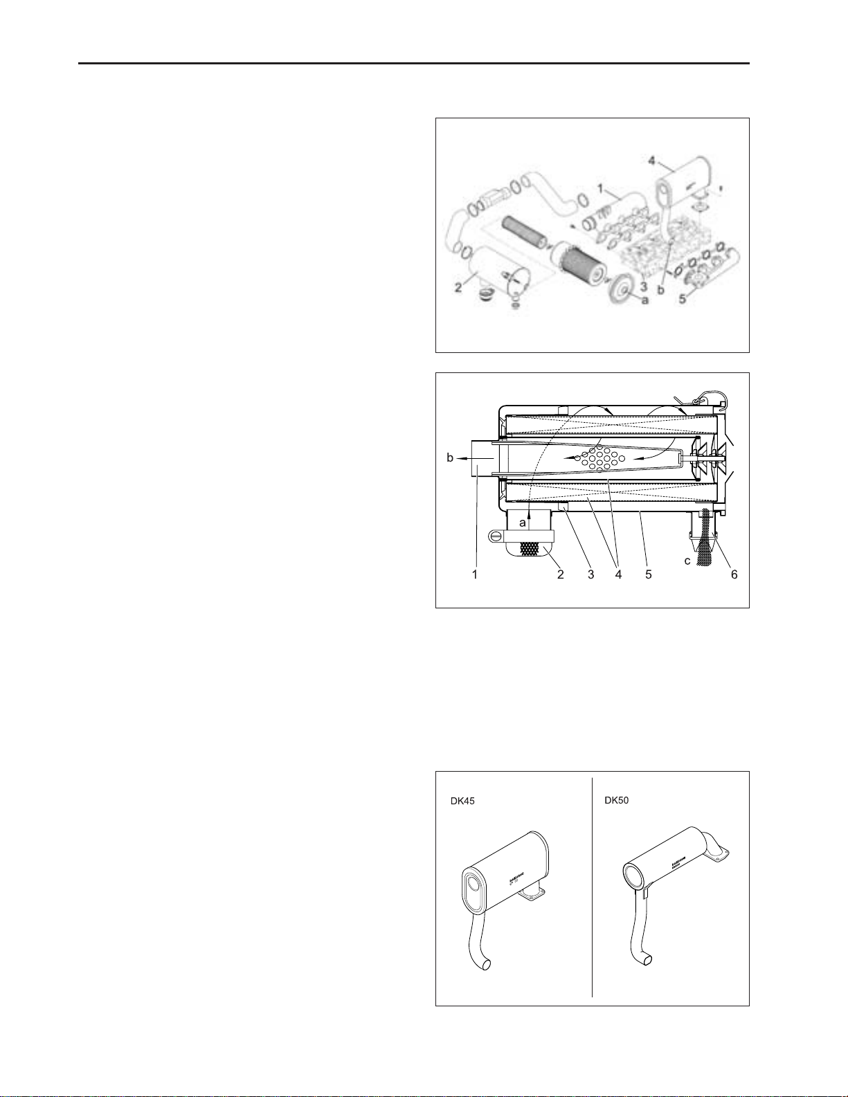
2.5 INTAKE AND EXHAUST SYSTEM
A . FLOW OF INT AKE AIR AND EXHAUST GAS
(a) Intake Air
(b) Exhaust Gas
(1) Intake Manifold
(2) Air Cleaner
(3) Cylinder Head
(4) Muffler
(5) Exhaust Manifold
B. AIR CLEANER
The air cleaner is dry-cyclone type and easy to maintain.
The air from the inlet port (2) circulates along the fin (3)
and around the air cleaner element (4) and the heavier
dust is carried to the evacuator (6), to the dust exhaust
port. The fine dust in the air is filtered with the air cleaner
element (4), and the filtered air flows to the outlet port
(1).
569W241A
C. MUFFLER
The exhaust noises are absorbed, while the gases are
passed through a series of holes on the inner tube
and glass wool of the muffler.
569W242A
(a) Inlet Air
(b) To Intake Manifold
(c) Heavier Dust
(1) Outlet Port (4) Air Cleaner Element
(2) Inlet Port (5) Body
(3) F in (6) Evacuator
569W243A
2-22
D569-W02 May-2003
Page 45

D. TURBOCHARGER (8454)
The mechanism of turbocharger is the use of exhaust
gas energy which rotates turbine and the power is
transmitted to air compressor by a shaft. So it is possible to supply more fuel to a cylinders and this will
increase the power.
It is recommended not to accelerate suddenly just about
starting or stopping the engine suddenly after driving.
Since the turbocharger runs above 100,000 rpm it is
necessary to allow the engine to idle for 1 or 2 minutes
before stopping, this protect the bearings of the turbocharger.
To keep a capacity of turbocharger you should check
the engine oil and air cleaner periodically. Turbocharger
is composed of precision parts. Do not disassemble
or repair without permission.
Turbocharger actuator pressure is 460 mmHg.
The structure of turbocharger is as above.
ENGINE
569W244A
(A) Compressor Ambient Air Inlet
(B) Compressor Air Discharge
(C) Turbine Exhaust Gas Inlet
(C) Turbine Exhaust Gas Inlet
(1) Turbine Wheel
(2) Compressor Wheel
(A) Fresh Air Inlet
(B) Exhaust Outlet
(C) Exhaust Inlet
569W245A
D569-W02 May-2003
(1) Compressed Air Outlet
(2) Compressor Seal
(3) Oil Inlet
(4) Journal Bearing
(5) Turbine Seal
(6) Turbine Wheel
(7) Compressor Wheel
(8) Thrust Bearing
(9) Oil Drain
2-23
Page 46

CHAPTER 2 8454
3. DISASSEMBLING AND SERVICING
3.1 TROUBLESHOOTING
Symptom Probable Cause
Engine Does Not Start
(Starter Does Not Run)
Engine Revolution is Not Smooth
• Not fuel
• Air in the fuel system
• Water in the fuel system
• Fuel pipe clogged
• Fuel filter clogged
• Excessively high viscosity of fuel
or engine oil at low temperature
• Fuel with low cetane number
• Fuel leak due to loose injection
pipe retaining nut
• Incorrect injection timing
• Fuel camshaft worn
• Injection nozzle clogged
• Injection pump malfunctioning
• Fuel transfer pump
malfunctioning
• Seizure of transfer pump
malfunctioning piston, cylinder
bore or bearing
• Compression leak from cylinder
• Improper valve seating, valve
spring broken, valve seized
• Improper valve timing
• Piston ring and bore worn
• Excessive valve clearance
• Battery discharged
• Starter malfunction
• Starter switch malfunction
• Wiring disconnected
• Fuel filter clogged or dirty
• Air cleaner clogged
• Fuel leak due to loose injection
pipe retaining nut
• Injection pump malfunctioning
• Incorrect nozzle opening
pressure
• Nozzle stuck or clogged
• Fuel over flow pipe clogged
• Governor malfunctioning
Solution
Replenish fuel
Vent air
Change fuel and repair or flush
fuel system
Clean
Clean or replace
Use the specified fuel or engine
oil
Use the specified fuel
Tighten nut
Adjust
Replace
Clean or replace
Repair or replace
Repair or replace
Repair or replace
Replace head gasket, tighten
cylinder head screws, glow plug
and nozzle holder
Repair or replace
Correct or replace timing gear
Repair or replace
Adjust
Charge
Repair or replace
Repair or replace
Connect
Clean or replace
Clean or replace
Tighten nut
Repair or replace
Adjust
Repair or replace
Clean
Repair
2-24
D569-W02 May-2003
Page 47

Symptom Probable Cause Solution
Either White or Blue Exhaust
Gas is Observed
Either Black or Dark Gray
Exhaust Gas is Observed
Insufficient Output
Excessive Lubrication Oil
Consumption
Fuel Mixed into
Lubricating Oil
Water Mixed Into Lubricating oil
Low Oil Pressure
• Excessive engine oil
• Piston ring and bore worn or
piston ring stuck
• Incorrect injection timing
• Insufficient compression
• Over heated
• Low grade fuel used
• Fuel filter clogged
• Air cleaner clogged
• Incorrect injection timing
• Engine’s moving parts seem to
be seizing
• Uneven fuel injection
• Insufficient nozzle injection
• Compression leak
• Piston ring’s gap facing the
same direction
• Oil ring worn or stuck
• Piston ring groove worn
• Valve stem and guide worn
• Crankshaft bearings, and crank
pin bearings worn
• Injection pump plunger worn
• Fuel transfer pump broken
• Head gasket defective
• Cylinder block or cylinder head
cracked
• Engine oil insufficient
• Oil strainer closed
• Oil filter cartridge clogged
• Relief valve stuck with dirt
• Relief valve spring weak or
broken
• Excessive oil clearance of
crankshaft bearings
• Excessive oil clearance of crank
pin bearings
• Excessive oil clearance of rocker
arm bushings
• Oil passage closed
• Improper type of oil
• Oil pump defective
ENGINE
Reduce to the specified level
Repair or replace
Adjust
Adjust top clearance
Lessen the load
Use the specified fuel
Clean or replace
Clean or replace
Adjust
Repair or replace
Repair or replace the injection
pump
Repair or replace the nozzle
Replace head gasket, tighten
cylinder head screws and nuts,
glow plug and nozzle holder
Shift ring gap direction
Replace
Replace the piston
Replace
Replace
Replace pump element or pump
Replace
Replace
Replace
Replenish
Clean
Replace
Clean
Replace
Replace
Replace
Replace
Clean
Use the specified type of oil
Repair or replace
D569-W02 May-2003
2-25
Page 48

CHAPTER 2 8454
Symptom Probable Cause Solution
High Oil Pressure
Engine Overheating
Battery Quickly Discharge
• Improper type of oil
• Relief valve defective
• Engine oil insufficient
• Fan belt broken or tensioned
improperly
• Cooling water insufficient
• Radiator net and radiator fin
clogged with dirt
• Inside of radiator corroded
• Cooling water flow route
corroded
• Radiator cap defective
• Water pipe damaged
• Thermostat defective
• Water pump defective
• Mechanical seal defective
• Overload running
• Head gasket defective
• Incorrect injection timing
• Unsuitable fuel used
• Battery electrolyte insufficient
• Fan belt slips
• Wiring disconnected
• Regulator defective
• Alternator defective
• Battery defective
Use the specified type of oil
Replace
Replenish
Replace or adjust
Replenish
Clean
Clean or replace
Clean or replace
Replace
Replace
Replace
Replace
Replace
Lesson the load
Replace
Adjust
Use the specified fuel
Replenish distilled water and
charge
Adjust belt tension or replace
Connect
Replace
Replace
Replace
2-26
D569-W02 May-2003
Page 49

3.2 SERVICING SPECIFICATIONS
A. ENGINE BODY
a. Cylinder Head
Item Factory Specification Allowable Limit
Cylinder Head Surface Flatness
Top Clearance
Cylinder Head Gasket Thickness Free
Tightened
Compression Pressure
(When cranking with starting motor)
* Variance of compression pressure among cylinders should be 10% or less.
0.75 ~ 0.9 mm
0.0295 ~ 0.0354 in.
1.3 ~ 1.5 mm
0.0512 ~ 0.0591 in.
1.15 ~ 1.25 mm
0.0453 ~ 0.0492 in.
3.24 ~ 3.73 MPa
33 ~ 38 kgf/cm
469 ~ 540 psi
2
ENGINE
0.05 mm / 100 mm
0.002 in. / 3.94 in.
-
-
2.55 MPa
26 kgf/cm
370 psi
2
b. Valves
Item
Valve Clearance (Cold) IN.
V alve Seat Angle IN.
V alve Face Angle IN.
Valve Recessing
Clearance Between Valve Stem and Valve
Guide
V alve Stem O.D
V alve Stem I.D
c. Valve Timing
0.25 mm 0.0098 in.
EX.
EX.
EX.
0.30 mm 0.0118 in.
1.047 rad. 60°
0.785 rad. 45°
1.047 rad. 60°
0.785 rad. 45°
0.2 ~ 0.5 mm
0.0079 ~ 0.0197 in.
0.040 ~ 0.070 mm
0.00157 ~ 0.00276 in.
7.960 ~ 7.975 mm
0.31339 ~ 0.31398 in.
8.015 ~ 8.030 mm
0.31555 ~ 0.31614 in.
Factory Specification
4A220 4A200T
015 mm 0.0059 in.
0.15 mm 0.0059 in.
1.047 rad. 60°
0.785 rad. 45°
1.047 rad. 60°
0.785 rad. 45°
0.2 ~ 0.5 mm
0.0079 ~ 0.0197 in.
0.040 ~ 0.070 mm
0.00157 ~ 0.00276 in.
7.960 ~ 7.975 mm
0.31339 ~ 0.31398 in.
8.015 ~ 8.030 mm
0.31555 ~ 0.31614 in.
Allowable Limit
0.8 mm
0.0315 in.
0.10 mm
0.0039 in.
-
-
Item Factory Specification Allowable Limit
Inlet V alve Open
Close
Exhaust V alve Open
Close
D569-W02 May-2003
0.140rad 8° before T.D.C
0.611rad 35° after B.D.C
0.785rad 45° before B.D.C
0.140rad 8° after T.D.C
-
-
2-27
Page 50

CHAPTER 2 8454
d. Cylinder Bore
Item Factory Specification Allowable Limit
Cylinder bore inner
diameter
e. Valve Spring
Free length
Assembling load / assembling length
Squareness
f. Rocker Arm
Rocker arm shaft O.D
Rocker arm bushing I.D
4A220
4A200T
Item Factory Specification Allowable Limit
Item Factory Specification Allowable Limit
87.000 ~ 87.022 mm
3.4252 ~ 3.4261 in.
83.000 ~ 83.022 mm
3.2677 ~ 3.2690 in.
41.7 ~ 42.2 mm
1.6417 ~ 1.6614 in.
12.0 kgf / 35.15 mm
26.46 lbs / 1.3839 in.
-
18.955 ~ 18.980 mm
0.74600 ~ 0.74724 in.
19.0 ~ 19.035 mm
0.74803 ~ 0.74941 in.
0.15 mm
0.0059 in.
41.2 mm
1.6220 in.
10.2 kgf / 35.15 mm
22.49 lbs / 1.3839 in.
1.0 mm
0.0394 in.
-
-
g. Tappet
Item Factory Specification Allowable Limit
Clearance between tappet and guide
Tappet O.D
Tappet guide I.D
h. Camshaft
Item Factory Specification Allowable Limit
Camshaft alignment
Cam height IN. (4A200T, 4A220)
EX. (4A200T, 4A220)
Clearance between camshaft
Camshaft journal O.D
Camshaft counter bore I.D
0.020 ~ 0.062 mm
0.00079 ~ 0.00244 in.
23.959 ~ 23.980 mm
0.94327 ~ 0.94410 in.
24.000 ~ 24.021 mm
0.94488 ~ 0.94571 in.
0.01 mm
0.0004 in.
33.90, 33.59 mm
1.3346, 1.3224 in.
33.70, 33.69 mm
1.3268, 1.3264 in.
0.050 ~ 0.091 mm
0.00197 ~ 0.00358 in.
39.934 ~ 39.950 mm
1.57221 ~ 1.57284 in.
40.000 ~ 40.025 mm
1.57480 ~ 1.57579 in.
0.07 mm
0.0028 in.
-
-
0.05 mm
0.0020 in.
33.85, 33.54 mm
1.3327, 1.3205 in.
33.65, 33.64 mm
1.3248, 1.3244 in.
0.15 mm
0.0059 in.
39.88 mm
1.5701 in.
-
2-28
D569-W02 May-2003
Page 51

I. Timing Gear
Item Factory Specification Allowable Limit
Timing gear backlash
Idle gear side clearance
Clearance between Idle gear shaft and idle
gear bushing
Idle gear shaft O.D
Idle gear bushing I.D
j. Piston Ring
Item Factory Specification Allowable Limit
Piston pin-bore I.D
Clearance between Oil ring and ring groove
Oil ring groove width
Oil ring width
Clearance between 2nd ring and ring groove
2nd ring groove width
2nd ring width
Top ring, oil ring end gap
2nd ring end gap
0.04 ~ 0.11 mm
0.0016 ~ 0.0043 in.
0.20 ~ 0.51 mm
0.0079 ~ 0.0201 in.
0.025 ~ 0.066 mm
0.00098 ~ 0.00260 in.
37.959 ~ 37.975 mm
1.49445 ~ 1.49508 in.
38.000 ~ 38.025 mm
1.49606 ~ 1.49705 in.
25.000 ~ 25.006 mm
0.98425 ~ 0.98448 in.
0.020 ~ 0.060 mm
0.00079 ~ 0.00236 in.
3.010 ~ 3.030 mm
0.11850 ~ 0.11929 in.
2.97 ~ 2.99 mm
0.11693 ~ 0.11772 in.
0.04 ~ 0.08 mm
0.00157 ~ 0.00315 in.
2.03 ~ 2.05 mm
0.07992 ~ 0.08070 in.
1.97 ~ 1.99 mm
0.07756 ~ 0.07834 in.
0.25 ~ 0.40 mm
0.0098 ~ 0.01570 in.
0.55 ~ 0.70 mm
0.0217 ~ 0.0276 in.
ENGINE
0.15 mm
0.0059 in.
0.9 mm
0.035 in.
0.1 mm
0.0039 in.
-
-
25.03 mm
0.9854 in.
0.15 mm
0.0059 in.
-
-
0.15 mm
0.0059 in.
-
-
1.25 mm
0.0492 in.
1.25 mm
0.0492 in.
k. Connecting Rod
Item Factory Specification Allowable Limit
Connecting rod misalignment
Clearance between Piston and small end
bushing
Piston pin O.D
Small end bushing I.D
D569-W02 May-2003
-
0.014 ~ 0.038 mm
0.00055 ~ 0.00150 in.
25.002 ~ 25.011 mm
0.98433 ~ 0.98469 in.
25.025 ~ 25.040 mm
0.98524 ~ 0.98583 in.
0.05 mm
0.0020 in.
0.15 mm
0.0059 in.
-
-
2-29
Page 52

CHAPTER 2 8454
l. Crankshaft
Item Factory Specification Allowable Limit
Crankshaft Misalignment
Clearance between Crankshaft and crank-
shaft bearing 1
Crankshaft O.D
Crankshaft bearing 1 I.D
Clearance between Crankshaft and crank-
shaft bearing 2
Crankshaft O.D
Crankshaft bearing 1 I.D
Clearance between Crank pin and crank pin
bearing
Crank pin O.D
Crank pin bearing I.D
Crankshaft side clearance
-
0.040 ~ 0.118 mm
0.00157 ~ 0.00465 in.
51.921 ~ 51.940 mm
2.04414 ~ 2.04489 in.
51.980 ~ 52.039 mm
2.04646 ~ 2.04878 in.
0.040 ~ 0.104 mm
0.00157 ~ 0.00409 in.
51.921 ~ 51.940 mm
2.04414 ~ 2.04488 in.
51.980 ~ 52.025 mm
2.04646 ~ 2.04823 in.
0.025 ~ 0.087 mm
0.00098 ~ 0.00343 in.
46.959 ~ 46.975 mm
1.84876 ~ 1.84947 in.
47.000 ~ 47.046 mm
1.85040 ~ 1.85221 in.
0.15 ~ 0.31 mm
0.0059 ~ 0.0122 in.
0.08 mm
0.0031 in.
0.20 mm
0.0079 in.
-
-
0.20 mm
0.0079 in.
-
-
0.20 mm
0.0079 in.
-
-
0.5 mm
0.020 in.
B. LUBRICA TING SYSTEM
a. Oil Pump
Item Factory Specification Allowable Limit
Engine oil pressure
(oil temp. 85 ~ 95 °C,
185 ~ 203 °F)
Clearance between inner rotor and outer rotor
Radial clearance between outer rotor and pump
End clearance between inner rotor and cover
At idle speed
At rated speed
more than 49.0 kPa
0.5 kgf/cm
2
7.11 psi
245 ~ 441 kPa
2.5 ~ 4.5 kgf/cm
2
35.6 ~ 64.0 psi
0.10 ~ 0.16 mm
0.0039 ~ 0.0063 in.
0.11 ~ 0.19 mm
0.0043 ~ 0.0078 in.
0.105 ~ 0.150 mm
0.00413 ~ 0.00591 in.
-
245 kPa
2.5 kgf/cm
35.6 psi
0.2 mm
0.0079 in.
0.25 mm
0.0098 in.
0.2 mm
0.00787 in.
2
2-30
D569-W02 May-2003
Page 53

C. COOLING SYSTEM
a. Thermostat
ENGINE
Valve opening temperature at beginning
69.5 ~ 72.5 °C (157.1 ~ 162.5 °F)
Opened completely (height 8 mm 0.315 in.)
b. Radiator
Radiator tightness
No leak at 137 kPa, 1.4 kgf/cm
10 seconds or more for pressure
Radiator cap tightness
Fan belt tension
[deflection at 98 N (10 kgf, 22 lbs) of force]
D. FUEL SYSTEM
a. Inject Pump
Injection timing (BTDC) 4A220
4A200T
b. Injection Nozzle
Fuel injection pressure
Fuel tightness of nozzle valve seat
85 °C (185 °F)
falling from 88 ~ 59 kPa
from 0.9 ~ 0.6 kgf/cm
from 13 ~ 9 psi
7 ~ 9 mm
0.28 ~ 0.35 in.
13.73 ~ 14.715 MPa
140 ~ 150 kgf/cm
2
1,991 ~ 2,134 psi
No fuel leak for 5 sec.
at pressure
12.74 MPa
130 kgf/cm
2
1,849 psi
2
, 20 psi
2
18°
12°
NOTE:
• Injection Sequence Four Cylinders: 1 → 3 → 4 → 2
(The cylinder number is given in order from the
gear case end.)
D569-W02 May-2003
2-31
Page 54

CHAPTER 2 8454
E. TIGHTENING TORQUES
Item
Cylinder head screws
Head cover nuts
* Bearing case screw 1
* Bearing case screw 2
* Flywheel screw
* Connecting rod screws
Rocker arm bracket studs
Drain plug
Glow plugs
Oil switch
Nozzle locating screws
Injection pipe nuts
Size x Pitch
M11 x 1.25
M10 x 1.25
M9 x 1.25
M10 x 1.25
M12 x 1.25
M8 x 1.0
M10 x 1.25
M12 x 1.25
M10 x 1.25
PT1/8
M20 x 1. 5
M12 x 1. 5
NOTE:
• For *marked screw, bolts and nuts on the table,
apply engine oil to their threads and seats before
tightening.
• The letter “M” in Size x Pitch means that the screw,
bolt or nut dimension stands for metric. The size is
the nominal outside diameter in mm of the threads.
The pitch is the nominal distance in mm between
two threads.
N•m
103.0 ~ 107.9
8.8 ~ 10.8
46.1 ~ 51.0
68.6 ~ 73.6
98.1 ~ 107.9
46.1 ~ 51.0
48.1 ~ 55.9
32.4 ~ 37.3
19.6 ~ 24.5
14.7 ~ 19.6
49.1 ~ 68.7
24.5 ~ 34.3
kgf•m
10.5 ~ 11.0
0.9 ~ 1.1
4.7 ~ 5.2
7.0 ~ 7.5
10.0 ~ 11.0
4.5 ~ 5.0
4.9 ~ 5.7
3.3 ~ 3.8
2.0 ~ 2.5
1.5 ~ 2.0
5.0 ~ 7.0
2.5 ~ 3.5
lbf·ft
75.9 ~ 79.6
6.5 ~ 8.0
34.0 ~ 37.6
50.6 ~ 54.2
72.3 ~ 79.6
34.0 ~ 37.6
35.4 ~ 41.2
23.9 ~ 37.3
14.5 ~ 18.1
10.8 ~ 14.5
36.2 ~ 50.6
18.1 ~ 25.3
2-32
D569-W02 May-2003
Page 55

3.3 CHECKING, DISASSEMBLING AND SERVICING
A . ENGINE DISASSEMBLED VIEW
ENGINE
(1) Cylinder Block
(2) Oil Pressure Switch
(3) Oil Pump
(4) Oil Pan
(5) Oil Strainer
(6) Oil Gauge
D569-W02 May-2003
(7) Cylinder Head
(8) Head Bolt
(9) Gear case
(10) Oil Filter
(11) Main bearing Case
Cover
(12) Bearing Case Bolt 1
(13) Main Bearing Case
(14) Bearing Case Bolt 2
(15) Rocker Arm
(16) Inlet, Exhaust Valve
(17) Cylinder Hear Cover
(18) Push Rod
(19) Tappet
(20) Camshaft
(21) Camshaft Gear
(22) Idle Gear
(23) Piston
(24) Connecting Rod
(25) Crankshaft
(26) Flywheel
(27) Flywheel Housing
(28) Starter
(29) Injection Pipe
(30) Glow Plug
(31) Nozzle
(32) Fuel Injection Pump
(33) Fuel Feed Pump
(34) Fuel Camshaft
(35) Fuel Camshaft Gear
(36) Engine Stop Solenoid
(37) Speed Control Plate
(38) Fork Lever (Governor)
(39) Impeller
(40) Thermostat
(41) Alternator
(42) Fan Drive Pulley
(43) Cooling Fan
(44) Radiator
(45) Reserve Tank Ass’y
(46) Inlet Manifold
(47) Muffler
615WA18A
(48) Exhaust Manifold
(49) Air Cleaner
(50) Turbo Charger
(51) Air Conditioner
Compressor
2-33
Page 56

Page 57

B. EXTERNAL COMPONENTS
a. Checking and Adjusting
1) Fan belt
Measure the deflection, depressing the belt halfway
between the fan drive pulley and the alternator pulley at
98 N (10 kgf, 22 lbs) of force.
If the deflection is not between the factory specifications,
loosen the bolts and nuts, and relocate the alternator
to adjust.
If the belt is damaged or worn (see figure), replace the
belt.
ENGINE
Belt tension
(deflection)
Factory spec 7 ~ 9 mm
0.28 ~ 0.35 in.
b. Disassembly and Assembly
1) Engine body
Drain the oil and the water, if disassemble the engine
body.
1. Remove the muffler and exhaust manifold (7).
2. Remove the starter (9) and the oil pressure switch
(8).
3. Pull out the oil gauge (6).
4. Remove the alternator (5) and the fan belt (1).
5. Remove the hour meter unit (2).
6. Loosen the oil filter (3) with a filter wrench and remove it and the oil filter flange (4).
* This figure does not show Hour meter Unit (2) cov-
ered with the cooling fan.
(When reassembling)
Apply liquid gasket (three bond 1,215 or equivalent) on
the thread of the oil pressure switch (8).
Apply liquid gasket to the both sides of the hour meter
gasket.
Apply oil to the O-ring and tighten the oil filter not with
wrench but by hand.
Adjust the fan belt tension (See fan belt).
569W249A
569W250A
(1) Fan Belt (6) Oil Gauge
(2) Hour Meter Unit (7) Exhaust Manifold
(3) Oil Filter (8) Oil Pressure
Switch
(4) Oil Filter Flange (9) Starter
(5) Alternator
Tightening
torque
D569-W02 May-2003
Oil pressure
switch
14.7 ~ 19.6 N·m
1.5 ~ 2.0 kgf·m
10.8 ~ 14.4 lbf·ft
2-35
Page 58

CHAPTER 2 8454
2) Solenoid
1. Disconnect the stop lever 1 (5) from the engine stop
lever (2).
2. Remove the screw (3) and (4).
3. Remove the solenoid (7) with its support.
(When reassembling)
• Loosen the solenoid mounting screws.
• Install the support and complete the linkage between the solenoid (7) and the engine stop lever
(2).
• Pushing the solenoid (7) plunger to the bottom, pull
the stop lever 2 (6) until the engine stop lever (2) is
turned to the end, then tighten the screws.
3) Intake manifold and fuel pipes
1. Disconnect the fuel pipe (3).
2. Loosen the injection pipe fitting with two wrenches
and remove the injection pipes (2).
3. Remove the intake manifold (1) and the fuel feed
pump (4).
569W251A
(1) Screw (5) Stop Lever 1
(2) Engine Stop Lever (6 ) Stop Lever 2
(3) Screw (7) Solenoid
(4) Screw
IMPORTANT:
• Tighten or loosen injection pipe fittings using the
one-hand two-wrench squeeze method.
• Cap the nozzle hole to prevent entrance of foreign
materials.
Tightening
torque
Injection pipe
nut 19 mm
(0.75 in.)
cross flats
24.5 ~ 34.3 N·m
2.5 ~ 3.5 kgf·m
18.0 ~ 25.3 lbf·ft
569W252A
(1) Intake Manifold (3) Fuel Pipe
(2) Injection Pipe ( 4) Fuel Feed Pump
2-36
D569-W03 May-2003
Page 59

C. ENGINE BODY
a. Checking and Adjusting
1) Compression pressure
1. Run the engine until warmed up.
2. Stop the engine and remove the air cleaner, the
muffler and all nozzle holders.
3. Connect a compression tester to the nozzle holder
hole.
4. Pull the stop lever to cut the fuel and run the engine
with the starter at 250 ~ 350 rpm for 5 ~ 10 seconds.
5. Measure the maximum pressure while running, sev-
eral times.
6. If the pressure does not reach the allowable limit,
apply a small amount of oil to the cylinder wall
through the nozzle holder hole and check the pressure again.
7. If the pressure raises after oil is apply, check the
cylinder wall and piston ring.
8. If the pressure is still low, check the top clearance,
valve clearance and cylinder head.
ENGINE
569W253A
Compression
pressure
Factory spec.
3.24 ~ 3.73 MPa
33 ~ 38 kgf/cm
2
469 ~ 540 psi
Allowable limit
2.55 MPa
26 kgf/cm
2
370 psi
Difference
Allowable limit
10 %
between two
cylinders
NOTE:
• Check the compression pressure with the specified
valve clearance for proper air in taking.
D569-W02 May-2003
2-37
Page 60

CHAPTER 2 8454
2) Valve clearance
1. Remove the cylinder head cover and the timing window cover on the flywheel housing and all glow
plugs.
2. Turn the flywheel and align the 1 TC or 1.4 TC mark
mark with the timing mark of window on the flywheel
housing to position the 1st cylinder valves at the top
head center during compression.
3. Measure the clearance at the valves marked with
in the table below with a feeler gauge.
4. If the clearance is not within the factory
specifications, turn the adjusting screw to adjust.
5. Turn the flywheel just one turn to position the 1st
cylinder valves at the top head center during overlap.
6. Measure the clearance at the valves marked with
in the table below with a feeler gauge.
7. If the clearance is not within the factory
specifications, adjust it.
569W254A
V alve
clearance
Factory
spec.
4A220
4A200T
In. : 0.25 mm 0.0098 in.
Ex. : 0.30 mm 0.0118 in.
In. : 0.15 mm 0.0059 in.
Ex. : 0.15 mm 0.0059 in.
Cylinder NO.
Valve
1
IN. EX.2IN. EX.3IN. EX.4IN. EX.
Checking
b. Disassembling and Assembling
1) Cylinder head cover, glow plugs and fuel
overflow pipes.
1. Remove the injection pipes and over flow pipe.
2. Remove the glow plugs.
3. Remove the injection nozzles and gaskets, heat
seals.
4. Remove the cylinder head cover.
(When reassembling)
• Check that the cylinder head cover gasket is not
defective.
• Tighten the cylinder head cover cap nuts in several
steps.
569W255B
569W256A
(1) Injection Nozzle ( 3 ) Heat Seal
(2) Gasket
2-38
D569-W03 May-2003
Page 61

2) Heat seal removal procedure
1. Drive screw driver lightly into the heat seal hole.
2. Turn screw driver three or four times each way.
3. While turning the screw driver, slowly pull the heat
seal put together with the injection nozzle gasket. If
the heat seal drops, repeat the above procedure.
4. Heat seal and injection nozzle gasket must be
changed when the injection nozzle is removed for
cleaning or for service.
NOTE:
• Use a philips screw driver that has a diameter
which is bigger than the heat seal hole 1/4 in.
φ
(approx.
6mm).
3) Rocker arm assembly
1. Loosen the nuts in several steps and the specified
sequence shown in the figure and remove them.
2. Remove the rocker arm assembly and the push rod.
ENGINE
569W257A
(1) Philips Screw Driver (2) Nozzle
(3) Injection Nozzle Gasket (4) Heat Seal
(When reassembling)
• Rest the end of push rod at the indent of tappet and
install the rocker arm assembly.
• Tighten the nuts in several steps and in the speci-
fied sequence to the specified torque. As shown in
the figure.
• Adjust the valve clearance after assembling the
rocker arm assembly.
IMPORTANT:
• When assembling the rocker arm assembly, locate
the groove of rocker arm shaft on stud bolt.
Tightening
torque
Stud, nut
48.1 ~ 55.9 N·m
4.9 ~ 5.7 kgf·m
35.3 ~ 41.2 lbf·ft
569W258B
569W259A
(1) Rocker Arm Shaft (3) Rocker Arm Bracket
(2) Rocker Arm (4) Screw
D569-W03 May-2003
2-39
Page 62

CHAPTER 2 8454
4) Cylinder head
1. Remove the screw in the specified sequence shown
in the figure and remove the cylinder head (1) and
head gasket.
2. Remove the water flange (2).
3. Take out the tappets from the cylinder block.
NOTE:
• Mark the cylinder number to the tappets to prevent
interchanging.
(When reassembling)
• Apply liquid gasket (Three bond 1215 or equivalent)
on the both sides of water flange gasket.
• Replace the head gasket with new one and place
on the cylinder block, be careful of its direction and
side.
• When using the head gasket shim, assemble the
shim first on the cylinder head.
• Before installing the tappets apply engine oil around
them.
569W260A
(1) Cylinder Head (2) Water Flange
IMPORTANT:
• Apply oil to the thread of screws and tighten in several steps and the specified sequence shown in the
figure to the specified torque.
• Check the torque after 30 minutes operation of the
assembled engine, and adjust valve clearance.
Tightening
torque
Cylinder
head
screws
103.0 ~ 107.9 N·m
10.5 ~ 11.0 kgf·m
75.9 ~ 79.6 lbf·ft
5) Valve
1. Compress the valve spring with a replaces and remove the collect (2).
2. Remove the retainer (3), valve spring (4), valve stem
seal (5) and the valve (1).
IMPORTANT:
• Do not interchange valves and valve parts.
• Mark the cylinder number on the valve and the parts
to prevent interchanging.
(When reassembling)
• Apply oil to the stem of valve and install in the cylinder head.
• Lubricate the valve and the parts after
reassembling.
569W261B
569W262A
(1) Valve (4) Valve Spring
(2) Collect (5) Valve Stem Seal
(3) Retainer
2-40
D569-W03 May-2003
Page 63
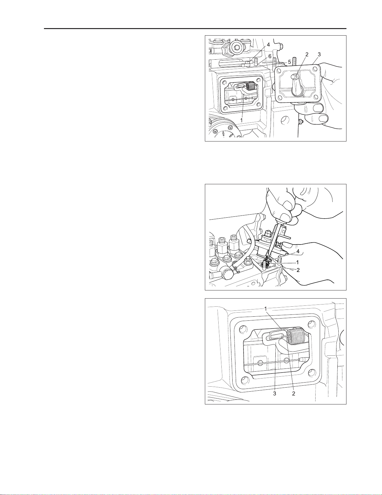
c. Timing Gears and Camshafts
1) Injection pump
1. Remove the injection pump cover (3) with the en-
gine stop lever (2).
2. Remove the injection pump.
(When reassembling)
• Apply liquid gasket to the both sides of injection
pump cover gasket and install it.
• Install the injection pump so that its control rack pin
(4) engages with the groove (5) of fork lever 1 (1).
• Install the injection pump cover with the arm of en-
gine stop lever (2) at the right of the arm of fork lever
1 (1).
2) Governor spring and Speed control plate
1. Disconnect the governor spring 1 (1) and 2 (2) from
the governor lever (4).
2. Remove the speed control plate.
3. Remove the governor spring.
ENGINE
569W263A
(1) Fork Lever 1 (4) Control Rack Pin
(2) Engine Stop Lever (5 ) Groove
(3) Injection Pump Cover (6) Shim
(When reassembling)
• Be careful not to drop the governor springs 1, 2 into
the gear case.
• Fix the governor springs (1), (2) to the fork lever 2
(3) and pull the springs, hook on to the governor
lever(4).
• Apply a liquid gasket both side of speed control plate
gasket.
569W265A
569W264A
(1) Governor Spring 1 (3 ) Fork Lever 2
(2) Governor Spring 2 (4 ) Governor Lever
D569-W02 May-2003
2-41
Page 64

CHAPTER 2 8454
3) Start spring
1. Remove the start spring (1) from the fork lever 1 (2).
(When reassembling)
• Be careful not to drop the start spring into the gear
case.
• Hook the start spring so that the longer hook is on
the fork lever side.
4) Fan drive pulley
1. Install the stopper to the flywheel so that the crankshaft may not turn.
2. Flatten the metal lock and loosen the crankshaft
nut (2).
3. Remove the fan drive fan drive pulley (1).
569W266A
(1) Start Spring (2) Fork Lever 1
Tightening
torque
Crankshaft
nut
137.3 ~ 156.9 N·m
14.0 ~ 16.0 kgf·m
101.3 ~ 115.7 lbf·ft
5) Gear case
1. Remove the gear case.
(When reassembling)
• Stick the O-ring (1) to the gear case with thin grease
to prevent from coming off during reassembling.
• Apply grease to the crankshaft oil seal lip on the
gear case and take care not to damage it when
installing.
• Apply liquid gasket (three bond 1215 or equivalent)
to the both sides of gear case gasket.
569W267A
(1) Fan Drive Pulley (2) Crankshaft Nut
569W268A
2-42
(1) O-Ring
D569-W02 May-2003
Page 65

6) Water pump and relief valve
1. Remove the water pump body (1).
2. Remove the relief valve cover (2) and take out the
ball, spring and seat.
(When reassembling)
• Install the relief valve cover (2) with its mark up.
ENGINE
Tightening
torque
Relief valve
cover screw
32.4 ~ 36.3 N·m
3.3 ~ 3.7 kgf·m
23.9 ~ 26.8 lbf·ft
7) Idle gear and crank gear
1. Remove the crankshaft collar (6), O-ring (5), oil
slinger (4) and crank gear collar (3) in the order.
2. Remove the idle gear (1).
3. Remove the crankshaft gear (2) with a special use
puller set.
(When reassembling)
• Heat the crankshaft gear to approx. 80 °C (176 °F)
and insert the crankshaft.
• Apply oil to the O-ring (5).
569W269A
(1) Water Pump Body (2) Relief Valve Cover
569W270A
IMPORTANT:
• Install the idle gear, aligning the alignment marks
referring to the figure.
569W271A
(1) Idle Gear (6) Crankshaft Collar
(2) Crankshaft Gear (7) Oil Pump Gear
(3) Crank Gear Collar (8 ) Injection Pump Gear
(4) Oil Slinger (9 ) Cam Gear
(5) O-Ring
D569-W02 May-2003
2-43
Page 66

CHAPTER 2 8454
8) Camshaft
1. Align the holes on the cam gear (2) with the crews
to loosen them through the holes with a T handle
wrench.
2. Draw out the camshaft (1).
3. Remove the cam gear (2).
(When reassembling)
• Heat the cam gear to approx. 80 °C (176 °F) and
insert the camshaft (1).
9) Fuel camshaft
1. Remove the fuel camshaft stopper.
2. Loosing the fork lever holder screws, remove the
fuel camshaft (4) with fork lever holder (5), fork lever
1 (1) and 2 (2).
3. Remove the Injection pump gear (3).
569W272A
(1) Camshaft (2) Cam Gear
(When reassembling)
• Heat the injection pump gear to approx. 80 °C (176 °F)
and insert the camshaft (4).
d. Connecting Rod and Piston
(A)Oil pan and oil filter
1. Remove the engine stand and the oil pan.
2. Remove the oil strainer (1).
(When reassembling)
• Be sure to install the O-ring (2) between the oil
strainer and the cylinder block.
569W273A
(1) Fork Lever 1 (4 ) Camshaft
(2) Fork Lever 2 (5 ) Fork Lever Holder
(3) Injection Pump Gear
2-44
569W274A
(1) Oil Strainer (2) O-Ring
D569-W02 May-2003
Page 67

(B) Piston and connecting rod
1. Remove the screws and the connecting rod cap.
2. Push out the rod and piston assembly.
(When reassembling)
• Apply oil to the crankpin bearing, cylinder wall and
connecting rod cap screw.
• Insert the rod and piston assembly with the mark
on the rod facing the injection pump, using a piston
ring compressor.
IMPORTANT:
• Mark the cylinder number on the piston and con-
necting rod to prevent interchanging.
• Carefully insert the piston and ring assembly in the
cylinder, compressing the rings not to damage the
chrome-plate on the piston rings.
• If connecting rod cap screws can not be screwed to
the end by hand, replace the screw.
(C) Piston ring and piston pin
1. Remove the piston rings with a piston ring replac-
ing tool.
2. Remove the piston pin.
ENGINE
569W276A569W275A
(When reassembling)
• Clean all the parts before assembling.
• Heat the piston in approx. 80 °C (176 °F) of oil for 10
to 15 minutes, when inserting the piston pin into
the piston.
569W277A
(1) Piston Pin
(2) Piston
(3) Piston Pin Snap Ring
(4) Compression Ring 1 = Top Ring
(5) Compression Ring 2 = Second Ring
(6) Oil Ring
(7) Connecting Rod
D569-W02 May-2003
2-45
Page 68

CHAPTER 2 8454
• Install the piston and connecting rod with the mark
FW on the piston to the flywheel and the mark on
the connecting rod to the injection pump.
• Install the piston rings with their manufacture’s
mark to the top of the piston.
• Install the expander in the oil ring with its gap opposite to the gap of oil ring.
• Install the top ring with its gap at 1.57 rad (90°) from
the piston pin to the exhaust port.
• Install the second ring and oil ring with their gap at
every 2.09 rad (120°).
569W278A
e. Crankshaft
(A)Flywheel
1. Install the stopper to the flywheel and loosen the
screw.
2. Remove the flywheel stopper and the flywheel.
(When reassembling)
• Clean the end of the crankshaft and the mating surface of the flywheel.
• Apply oil to flywheel screws.
• Fit the flywheel hole to crankshaft hole and lighten
the flywheel bolts to specified torque.
NOTE:
• Screw longer screws into the flywheel to carry. It if
needed.
Tightening
torque
Flywheel
screw
98.1 ~ 107.9 N·m
10.0 ~ 11.0 kgf·m
72.3 ~ 79.6 lbf·ft
569W279A
(7) Connecting Rod (11 ) Expander Joint
(8) Connecting Rod Cap (12) Oil Ring Gap
(9) Casting Mark (13) Manufacturer’s Mark
(10) Mark(The Side Face)
569W280A
2-46
D569-W02 May-2003
Page 69

(B) Bearing case cover
Loosen the screw first inside and next outside, and lift
the cover (1) by screwing two screws gradually and
evenly, referring to the photo.
(When reassembling)
• Apply grease to the oil seal lip and take care that it
is not rolled when installing.
ENGINE
Tightening
torque
Bearing
case
cover screw
23.5 ~ 27.5 N·m
2.4 ~ 2.8 kgf·m
17.4 ~ 20.3 lbf·ft
(C) Crankshaft
1. Remove the bearing case screw 2.
2. Pull out the crankshaft, taking care not to damage
the crankshaft bearing 1.
(When reassembling)
• Apply oil to the bearing case screw 2.
• Clean the oil passage of the crankshaft with com-
pressed air.
Tightening
torque
Main bearing
case screw
2
68.7 ~ 73.6 N·m
7.0 ~ 7.5 kgf·m
50.6 ~ 54.2 lbf·ft
(D) Main bearing case
1. Remove the bearing case screws 1 (4) and remove
the main bearing case 1, 2, 3 (1).
2. Remove the thrust bearing from the flywheel end of
the bearing case.
569W281A
(1) Bearing Case Cover
569W282A
D569-W02 May-2003
569W283A
(1) Main Bearing Case 1, 2, 3
(2) Thrust Bearings
(3) Main Bearing Case Assembly 1
(4) Bearing Case Screw 1
(5) Crankshaft Bearing 2
2-47
Page 70

CHAPTER 2 8454
IMPORTANT:
• Mark a location line (6) to the bearing case, to prevent interchanging.
(When reassembling)
• Clean the parts and the oil passage of the bearing
case.
• Apply oil to the journal, bearing inserts and the bearing case screws.
• Place the thrust bearings on the bearing case with
their oil groove outside.
• Install the main bearing case with the mark “FLY
WHEEL” toward the flywheel.
Tightening
torque
Bearing
case screw
1
46.1 ~ 51.0 N·m
4.7 ~ 5.2 kgf·m
34.0 ~ 37.6 lbf·ft
D. SERVICING
a. Cylinder Head and Valve
(A) Cylinder head surface flatness
1. Thoroughly clean the cylinder head surface.
2. Place a straight edge on the cylinder head and measure the clearance with a feeler gage as shown in
the figure.
3. If the measurement exceeds the allowable limit, replace the cylinder head.
569W284A
(6) Bearing Case
IMPORTANT:
• Do not place the straight edge on the combustion
camber.
Flatness
Allowable
limit
0.05 mm
0.0019 in.
(B) Cylinder head surface flaw
1. Prepare an air spray red check.
2. Clean the cylinder head surface with the detergent
(B).
3. Spray the cylinder head surface with the red permeative liquid (A).
4. Wash away the red permeative liquid on the cylinder head surface with the detergent (B) after ten
minutes.
5. Spray the cylinder head surface with the white developer (C).
6. If any flaw is found such as a red mark, replace the
cylinder head.
569W285A
569W286A
(A) Red Permeative Liquid ( C) White Developer
(B) Detergent
2-48
D569-W02 May-2003
Page 71

(C) Valve stem clearance
1. Remove the carbon from the valve guide.
2. Measure the valve stem O.D. with an outside
micrometer.
3. Measure the valve guide I.D. of cylinder head, and
calculate the clearance.
4. If the measurement exceeds the allowable limit,
replace the valve guide of the valve.
Valve stem
clearance
V alve guide
bore I.D.
Valve stem
O.D.
Factory
spec.
Allowable
limit
Factory
spec.
Factory
spec.
0.040 ~ 0.070 mm
0.00157 ~ 0.00276 in.
0.1 mm
0.004 in.
8.015 ~ 8.030 mm
0.31555 ~ 0.31614 in.
7.960 ~ 7.975 mm
0.31339 ~ 0.31398 in.
(D) Valve recessing
1. Clean the cylinder head, the valve face and the seat.
2. Insert the valve in the guide.
3. Measure the valve recessing with a depth gauge.
4. If the recessing exceeds the allowable limit, replace
the valve and check the valve seating.
ENGINE
569W287A
12 13111078210 65439
Valve
recessing
Factory
spec.
Allowance
0.2 ~ 0.5 mm
0.0078 ~ 0.0197 in.
0.8 mm
0.0315 in.
(E)Valve seat
1. Coat the valve face lightly with red lead and put the
valve on its seat to check the contact.
2. If the valve does not seat all the way around the
valve seat or the valve contact is less than 70%,
correct the valve seating as follows.
3. Apply compound on the valve face evenly.
4. Put the valve on its seat hold it with the valve flapper.
5. Turn and flap the valve back and forth on the valve
seat to lap.
6. Remove the compound and clean the valve and the
seat.
7. Apply oil on the valve face and finish to complete
fitting.
8. Repeat lapping until the valve seats correctly.
569W288A
569W289A
D569-W02 May-2003
2-49
Page 72

CHAPTER 2 8454
(F) Valve spring
1. Measure the free length of the spring with venire
calipers.
2. Place the spring on a spring compression tester and
compress to the specified length, and get the tension.
3. If the measurement is less than the allowable limit,
replace the valve spring.
Tension
Factory
spec.
117 N/35.15 mm
12.0 kgf/35.15 mm
26.5 lbs/1.3839 in.
Allowable
limit
100 N/35.15 mm
10.2 kgf/35.15 mm
22.5 lbs/1.3839 in.
Free length
Factory
spec.
Allowable
limit
41.7 ~ 42.2 mm
1.6417 ~ 1.6614 in.
41.2 mm
1.622 in.
(G) Valve spring squareness (Tilt)
1. Place the spring on the surface plate, and a square
at its side.
2. Measure the maximum distance “A” (see figure),
rotating spring.
3. If the measurement exceeds the allowable limit replace.
Valve spring
square ness
Allowable
limit
1.0 mm
0.039 in.
569W290A
(H) Rocker arm bushing and shaft clearance
1. Measure the rocker arm I.D. with an inside micrometer.
2. Measure the rocker arm shaft O.D. with an outside
micrometer.
3. If the clearance exceeds the allowable limit, replace
the rocker arm.
4. If the clearance still exceeds the allowable limit after
replacing the rocker arm replace the rocker arm shaft.
Clearance
Rocker arm
shaft O.D.
Rocker
arm I.D.
Factory
spec.
Allowable
limit
Factory
spec.
Factory
spec.
0.020 ~ 0.070 mm
0.00079 ~ 0.00276 in.
0.15 mm
0.0059 in.
18.955 ~ 18.980 mm
0.74626 ~ 0.74724 in.
19.000 ~ 19.025 mm
0.74803 ~ 0.74902 in.
2-50
9
10
11
D569-W02 May-2003
569W291A
569W292A
Page 73

b. Timing Gears and Camshafts
(A) Timing gear backlash
1. Set a dial indicator (lever type) with its tip on the
gear tooth.
2. Move the gear to measure the backlash, holding its
mating gear.
3. If the backlash exceeds the allowable limit, check
the oil clearance of the shafts and the gear.
4. If the oil clearance is proper, replace the gear.
ENGINE
Clearance
Factory
spec.
Allowable
limit
0.04 ~ 0.11 mm
0.0016 ~ 0.0043 in.
0.15 mm
0.0059 in.
(B) Idle gear side clearance
1. Pull the idle gear collar 2 (1) and push the idle gear
(2) to each end.
2. Measure the clearance A between the idle gear and
the idle gear collar 2 (1) with a feeler gauge.
3. If the clearance exceeds the allowable limit, replace
the idle gear collar 1 (3).
Side
clearance
Factory
spec.
Allowable
limit
0.20 ~ 0.51 mm
0.0079 ~ 0.021 in.
0.9 mm
0.035 in.
569W293A
569W294A
(C) Cam gear side clearance
1. Pull the cam gear (2) with the camshaft (1) to its
end.
2. Measure the clearance A between the cam gear (2)
and the camshaft stopper (3).
3. If the clearance exceeds the allowable limit, replace
the camshaft stopper (3).
Side
clearance
Factory
spec.
Allowable
limit
0.07 ~ 0.22 mm
0.0028 ~ 0.0087 in.
0.3 mm
0.0118 in.
D569-W02 May-2003
(1) Idle Gear Collar 2 ( 3) Idle Gear Collar 1
(2) Idle Gear
569W295A
(1) Camshaft (3) Camshaft Stopper
(2) Cam Gear
2-51
Page 74

CHAPTER 2 8454
(D) Injection pump gear side clearance
1. Pull the fuel camshaft and pull the injection pump
gear (1) to each end.
2. Measure the clearance (A) between the injection
pump gear (1) and the snap ring (2) on the fuel
camshaft.
3. If the clearance exceeds the allowable limit, check
the gear, the bearing and the key.
Side
clearance
Factory
spec.
Allowable
limit
0.15 ~ 0.57 mm
0.0059 ~ 0.0224 in.
0.9 mm
0.035 in.
(E) Idle gear oil clearance
1. Measure the idle gear shaft O.D. with an outside
micrometer.
2. Measure the idle gear bushings I.D. with an inside
micrometer.
3. If the clearance exceeds the allowable limit, replace
the bushing.
Oil
clearance
Shaft
O.D.
Bushing
I.D.
Factory
spec.
Allowable
limit
Factory
spec.
Factory
spec.
0.025 ~ 0.066 mm
0.00098 ~ 0.00259 in.
0.1 mm
0.004 in.
37.959 ~ 37.975 mm
1.4944 ~ 1.4950 in.
38.000 ~ 38.025 mm
1.4961 ~ 1.4970 in.
569W296A
(1) Injection Pump Gear (2) Snap Ring
(A) Clearance
569W297A
(F) Replacing idle gear bushings
1. Press out the bushings using an idle gear bushing
replacing tool.
2. Clean the bushings and the bore, and apply oil to
them.
3. Press in the bushing using the replacing tool.
2-52
569W298A
D569-W02 May-2003
Page 75

(G) Camshaft oil clearance
1. Measure the I.D. of the camshaft bore on the crank-
case with an inside micrometer.
2. Measure the O.D. of the camshaft journal with an
outside micrometer.
3. If the clearance exceeds the allowable limit, replace
the shaft.
ENGINE
Oil
clearance
Journal
O.D.
Bore
I.D.
Factory
spec.
Allowable
limit
Factory
spec.
Factory
spec.
0.050 ~ 0.091 mm
0.00197 ~ 0.00358 in.
0.15 mm
0.0059 in.
39.934 ~ 39.950 mm
1.57221 ~ 1.57284 in.
40.000 ~ 40.025 mm
1.57480 ~ 1.57579 in.
(H) Camshaft alignment
1. Support the camshaft with V blocks on the surface
plate at both end journals and set a dial indicator
with its tip on the intermediate journal.
2. Rotate the camshaft in the V block and get the ec-
centricity (half of the measurement).
3. If the eccentricity exceeds the allowable
Eccentricity
Allowable
limit
0.05 mm
0.002 in.
569W299A
(I) Cam height
1. Measure the height of the camshaft lobes at their
largest. O.D. with an outside micrometer.
2. If the measurement is less than the allowable limit,
replace the camshaft.
Cam
height
4A220
4A200T
(IN.)
(EX.)
(IN.)
(EX.)
specification
allowable limit
specification
allowable limit
specification
allowable limit
specification
allowable limit
33.59 mm 1.322 in.
33.54 mm 1.320 in.
33.69 mm 1.326 in.
33.64 mm 1.324 in.
33.90 mm 1.335 in.
33.85 mm 1.333 in.
33.70 mm 1.327 in.
33.65 mm 1.325 in.
569W2A0A
569W2A1A
D569-W02 May-2003
2-53
Page 76

CHAPTER 2 8454
c. Connecting Rod and Piston
(A) Piston pin bore
1. Measure the I.D. of the piston pin bore in piston
(lengthwise and widthwise of the piston) with a cylinder gauge.
2. If the measurement exceeds the allowable limit,
replace the piston.
Piston pin
bore I.D.
Factory
spec.
Allowable
limit
25.000 ~ 25.006 mm
0.9843 ~ 0.9845 in.
25.03 mm
0.9854 in.
(B) Piston pin and brushing clearance
1. Measure the piston pin O.D. with an outside
micrometer.
2. Measure the piston pin busing I.D. with an inside
micrometer.
3. If the clearance exceeds the allowable limit with new
bushing, replace the piston pin.
Piston pin
and
bushing
clearance
Piston pin
O.D.
Bushing
I.D.
Factory
spec.
Allowable
limit
Factory
spec.
Factory
spec.
0.014 ~ 0.038 mm
0.00055 ~ 0.00150 in.
0.15 mm
0.0059 in.
25.002 ~ 25.011 mm
0.98433 ~ 0.98469 in.
25.025 ~ 25.040 mm
0.98524 ~ 0.98583 in.
569W2A2A
9
10
11
569W2A3A
(C) Replacing the piston pin bushing
1. Press out the bushing, using a piston pin bushing
replacing tool.
2. Clean the new bushing and the bore and apply oil
to them.
3. Press in the bushing, using the replacing tool.
IMPORTANT:
• Align the oil holes of the connecting rod and the
bushing.
2-54
569W2A4A
D569-W02 May-2003
Page 77

(D) Piston ring end gap
1. Push the ring into the cylinder to the lower limit of
the ring travel in the assembled engine with a piston.
2. Measure the ring gap with a feeler gauge.
3. If the gap exceeds the allowable limit, replace the
piston ring.
ENGINE
Piston
ring
end
gap
2nd
ring
Top
ring,
oil ring
Factory
spec.
Allowable
limit
Factory
spec.
Allowable
limit
0.55 ~ 0.70 mm
0.0217 ~ 0.0276 in.
1.25 mm
0.0492 in.
0.25 ~ 0.40 mm
0.0098 ~ 0.0157 in.
1.25 mm
0.0492 in.
(E) Piston ring clearance
1. Clean the ring and the ring grooves, and install each
ring into its groove.
2. Measure the clearance between the ring and the
groove with a feeler gauge.
3. If the clearance exceeds the allowable limit, replace
the piston ring.
4. If the clearance still exceeds the allowable limit with
a new ring, replace the piston.
Piston
ring
clearance
2nd
ring
Oil ring
Factory
spec.
Allowable
limit
Factory
spec.
Allowable
limit
0.04 ~ 0.08 mm
0.00157 ~ 0.00314 in.
0.15 mm
0.0059 in.
0.02 ~ 0.06 mm
0.00079 ~ 0.00236 in.
0.15 mm
0.0059 in.
569W2A5A
569W2A6A
D569-W02 May-2003
2-55
Page 78

CHAPTER 2 8454
(F) Connecting rod alignment
1. Remove the connecting rod bearing and install the
bearing cap.
2. Install the piston pin in the connecting rod.
3. Install the connecting rod on the connecting rod
alignment tool.
4. Put a gauge over the piston pin and move it against
the face plate.
5. If the gauge does not fit squarely against the face
plate, measure the space between the pin of the
gauge and the face plate.
6. If the measurement exceeds the allowable limit,
replace the connecting rod.
569W2A7A
Space between
gauge pin and
face plate
Allowable
limit
0.05 mm (0.0020 in.)
at 100 mm (3.94 in.)
of gauge pin span
d. Crankshaft
(A) Flywheel deflection and crankshaft end play
1. Set a dial indicator with its tip on the rear friction
face of the flywheel near the edge.
2. Turn the flywheel and measure the deflection or the
uneven wear.
3. If the measurement exceeds the allowable limit,
remove the flywheel and check the mating faces of
the crankshaft and flywheel.
4. If scored of worn excessively, resurface or replace
the flywheel.
5. Move the crankshaft with flywheel back and forth to
each end and measure the end play.
6. If the play exceeds the allowable limit, replace the
side bearing.
Deflection
End play
Allowable
limit
Factory
spec.
Allowable
limit
0.05 mm
0.0020 in.
0.15 ~ 0.31 mm
0.0059 ~ 0.0122 in.
0.5 mm
0.020 in.
569W2A8A
2-56
D569-W02 May-2003
Page 79

(B) Crankshaft alignment
1. Support the crankshaft with V blocks on the surface
plate at its front and rear journals and set a dial
indicator with its tip on the intermediate journal.
2. Rotate the crankshaft in the V blocks and get the
misalignment (half of the measurement).
3. If the misalignment exceeds the allowable limit, re-
place the crankshaft.
ENGINE
Misalignment
allowable
limit
0.08 mm
0.0031 in.
(C) Crankshaft journal and bearing 1 oil clearance
1. Measure the I.D. of the crankshaft bearing 1 with an
inside micrometer.
2. Measure the O.D. of the crankshaft journal with an
outside micrometer.
3. If the clearance exceeds the allowable limit, replace
the bearing referring to Replacing Crankshaft Bearing 1.
Oil
clearance
Journal
O.D.
Bearing 1
I.D.
Factory
spec.
Allowable
limit
Allowable
limit
Allowable
limit
0.040 ~ 0.118 mm
0.00157 ~ 0.00465 in.
0.20 mm
0.0079 in.
51.921 ~ 51.940 mm
2.04413 ~ 2.04488 in.
51.980 ~ 52.039 mm
2.04646 ~ 20.4878 in.
569W2A9A
9
10
11
569W2B0A
(D) Replacing crankshaft bearing 1
1. Press out the crankshaft bearing 1 with replacing
tool.
2. Clean a new crankshaft bearing 1 and bore, and
apply engine oil to them.
3. Press fit a new bearing 1 using a inserting tool,
taking due care to see that the seam of bearing 1
faces the exhaust manifold side.
D569-W02 May-2003
569W2B1A
(1) Seam
2-57
Page 80

CHAPTER 2 8454
(E) Crankshaft Journal and Bearing 2 Oil Clearance
1. Put plastic gauge lengthwise in the center of the
journal.
2. Install the bearing cap and tighten the screw to the
specified torque once, and remove the cap again.
3. Measure the amount of the flattening with the scale
and get the oil clearance.
4. If the clearance exceeds the allowable limit, replace
replace the bearing.
Oil
clearance
Journal
O.D.
Bearing 2
I.D.
(F) Crankpin and connecting rod bearing 2 oil clear-
ance
1. Put a strip of PLASTIGAGE lengthwise in the center
of the crankpin.
2. Install the connecting rod and tighten the screws to
the specified torque once, and remove the cap again.
3. Measure the amount of the flattening with the scale
and get the oil clearance.
4. If the clearance exceeds the allowable limit, replace
the bearing.
Oil
clearance
Journal
O.D.
Bearing 1
I.D.
Factory
spec.
Allowable
limit
Allowable
limit
Factory
spec
Factory
spec.
Allowable
limit
Factory
spec.
Factory
spec.
0.040 ~ 0.104 mm
0.00157 ~ 0.00409 in.
0.20 mm
0.0079 in.
51.921 ~ 51.940 mm
2.04413 ~ 2.04488 in.
51.980 ~ 52.025 mm
2.04646 ~ 2.04823 in.
0.025 ~ 0.087 mm
0.00098 ~ 0.00343 in.
0.20 mm
0.0079 in.
46.959 ~ 46.975 mm
1.84878 ~ 1.84941 in.
47.000 ~ 47.046 mm
1.85040 ~ 1.85221 in.
569W2B2A
2-58
D569-W02 May-2003
Page 81

e. Cylinder Bore
(A) Cylinder bore diameter
1. Measure the cylinder liner I.D. at sit positions shown
in the figure to find the maximum wear.
4A200T
4A220
83.000 ~ 83.022 mm
3.2677 ~ 3.269 in.
87.000 ~ 87.022 mm
3.4252 ~ 3.4261 in.
.
ENGINE
569W2B3A
(A) Axial Direction
(B) Transverse Direction
1,2,3 Measuring Points
569W2B4A
D569-W02 May-2003
2-59
Page 82

CHAPTER 2 8454
E. LUBRICA TING SYSTEM
a. Checking
(A) Engine oil pressure
1. Remove the oil pressure switch and install adaptors and pressure tester.
2. Start the engine and run it until it is warmed up, and
measure the oil pressure both at idling and rated
speed.
3. If the oil pressure is less than the allowable limit,
check the amount of oil, oil filter, oil pump relief
valve, oil passages and oil clearance.
Engine
oil pres-
sure
At idle
speed
At rated
speed
Factory
spec.
Factory
spec.
Allowable
limit
more than 49 kPa
0.5 kgf/cm
2
7.11 psi
294 ~ 441 kPa
2.5 ~ 4.5 kgf/cm
35.6 ~ 64.0 psi
245 kPa
2.5 kgf/cm
2
35.6 psi
2
569W2B5A
(Reference)
Tightening
torque
Oil
pressure
switch
14.7 ~ 19.6 N·m
1.5 ~ 2.0 kgf·m
10.8 ~ 14.5 lbf·ft
(B) Oil filter and relief valve
1. Drain the engine oil and remove the oil filter to check
it.
2. Check the relief valve for dirt, and the seat (2) and
ball (1) for damage.
3. If damaged, replace.
4. Check the free length of spring (3).
5. If it is less than the allowable limit, replace it.
Spring free
length
Factory
spec
Allowable
limit
35 mm
1.38 in.
30 mm
1.18 in.
NOTE:
• Install the relief valve cover with the mark up.
569W2B6A
(1) Relief Valve Ball (3 ) Relief Valve Spring
(2) Relief Valve Seat
Tightening
torque
2-60
Relief
cover
32.4 ~ 36.3 N·m
3.3 ~ 3.7 kgf·m
23.9 ~ 36.8 lbf·ft
D569-W02 May-2003
Page 83
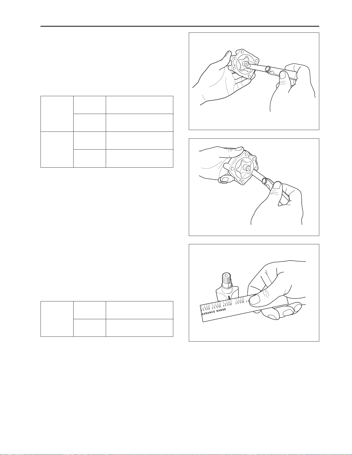
b. Servicing
(A) Rotor and lobe clearance of oil pump
1. Measure the clearance between the outer and inner rotor with a feeler gauge.
2. Measure the clearance between the outer and the
housing with a feeler gauge.
3. If the clearance exceeds the allowable limit, replace
the pump.
ENGINE
Outer
and inner
rotor
clearance
Outer
and inner
housing
clearance
Factory
spec.
Allowable
limit
Factory
spec.
Allowable
limit
0.10 ~ 0.16 mm
0.0039 ~ 0.0063 in.
0.20 mm
0.0079 in.
0.11 ~ 0.19 mm
0.0043 ~ 0.0075 in.
0.25 mm
0.0098 in.
(B) Rotor end clearance of oil pump
1. Put a strip of PLASTIGAGE on the rotor and assemble the pump.
2. Disassemble the pump and measure the amount
of the flattening with the scale to get the clearance.
3. If the clearance exceeds the allowable limit, replace
the pump.
569W2B7A
569W2B8A
End
clearance
Factory
spec.
Allowable
limit
D569-W02 May-2003
0.105 ~ 0.150 mm
0.00423 ~ 0.00591 in.
0.20 mm
0.0079 in.
569W2B9A
2-61
Page 84

CHAPTER 2 8454
F. COOLING SYSTEM
a. Checking Adjusting
(A) Fan belt
1. Measure the deflection, by depressing the belt halfway between the fan drive pulley and the alternator
pulley at 98 N (10 kgf, 22 lbs) of force.
2. If the deflection is not between the factory specifications, loosen the bolts and nuts, and relocate the
alternator to adjust.
3. If the belt is damaged or worn (see figure), replace
the belt.
Belt
tension
(direction)
Factory
spec
7 ~ 9 mm
0.28 ~ 0.35 in.
at 98 N (10 kgf, 22 lbs)
of force
(B) Radiator water tightness
1. Fill the radiator with water to the specified amount
and warm up the engine.
2. Set a radiator tester and raise the water pressure to
the specified pressure.
3. Check the radiator for water leaks.
4. For water leaks from a pin hole, repair it with radiator cement, and for larger leaks, replace the radiator.
Radiator
water
tightness
Factory
spec
No leaks at 137 kPa
(1.4 kgf/cm2, 20 psi)
(C) Radiator cap tightness
1. Set a radiator tester on the radiator cap.
2
2. Apply 88 kPa (0.9 kgf/cm
, 13 psi) of pressure and
measure the pressure for 10 seconds.
2
3. If the pressure falls below 59 kPa (0.6 kgf/cm
, 9
psi),replace the radiator cap.
569W2C0A
569W2C1A
Radiator
cap
tightness
2-62
Factory
spec
more than 10 seconds
for pressure fall
from 88 ~ 59 kPa
(0.9 ~ 0.6 kgf/cm2, 13 ~ 9 psi)
569W2C2A
D569-W02 May-2003
Page 85

b. Disassembling and Assembling
(A) Thermostat
1. Remove the thermostat cover (2).
2. Take out the thermostat (1).
(When reassembling)
• Apply liquid gasket (Three Bond 1215 or equivalent)
to the gasket.
(B) Water pump
1. Remove the fan and fan pulley.
2. Remove the water pump body from gear case cover.
3. Remove the water pump flange (1).
4. Remove the impeller and water pump shaft (3).
5. Remove the impeller from the water pump shaft.
6. Remove the mechanical seal (5).
ENGINE
569W2C3A
(1) Thermostat (2 ) Thermostat Cover
(When reassembling)
• Replace the mechanical seal (5) with new one.
c. Servicing
(A) Thermostat valve opening temperature
1. Suspend the thermostat in the water by a string with
its end inserted between the valve and seat.
2. Heating the water gradually, read the temperatures
when the valve starts to opens and when the valve
is completely opened approx 8 mm (0.315 in.).
3. If the measurements are not within the factory speci-
fications, replace the thermostat.
Opening
temperature
Factory
spec.
71 ± 1.5 °C
(160 ± 3 °F)
at beginning
Lower than 85 °C (185 °F)
at 8 mm (0.315 in.)
of opening
569W2C4A
(1) Water Pump Flange (4) Water Pump Body
(2) Water Pump Bearing (5) Mechanical Seal
(3) Water Pump Shaft (6 ) Impeller
569W2C5A
D569-W02 May-2003
2-63
Page 86

CHAPTER 2 8454
G. FUEL SYSTEM
a. Checking and Adjusting
1) Injection pump
(A) Injection term (Injection timing)
1. Remove the injection pipes.
2. Set the speed control lever to the maximum fuel
discharge position.
3. Turn the flywheel counterclockwise (facing the
flywheel) until the fuel flows through the hole of the
delivery valve holder (1).
4. Turn the flywheel further and stop turning when the
fuel stops to flow, to check the injection timing.
5. If the Fl mark does not align with the mark of the
window on flywheel housing, add or remove the
shim (2) to adjust.
569W2C6A
(1) Delivery Valve Holder (2 ) Shim
Injection
timing
4A220
4A200T
0.31 rad, 18°
before T.D.C
0.21 rad, 12°
before T.D.C
NOTE:
• Apply liquid gasket (There Bond 1215 or equivalent)
to the shim, when reassembling.
(Reference)
• The timing advances by removing 0.15 mm (0.006
in.) of shim and retards by adding one, approx 0.26
rad (1.5°) of crank angle.
• Approx 3.6 mm (0.142 in.) of turn at outer rim of
flywheel equals 0.26 rad (1.5°) of crank angle.
2-64
D569-W02 May-2003
Page 87

(B)Delivery valve fuel tightness
1. Remove the injection pipes, glow plugs and the in-
let manifold, and install a pressure tester.
2. With the speed control lever at the fuel injection po-
sition, turn the crankshaft counterclockwise (facing
the flywheel) until the pressure builds up to the fuel
injection pressure.
3. Release the pressure in the delivery chamber by
moving down the plunger to bottom dead center
(turn the crankshaft clockwise approx 1.57 rad (90°)
from the FI timing).
4. If the pressure drops for 5 seconds exceeds the
allowable limit, replace the delivery valve or pump
assembly.
5. If the pressure does not built up, replace the pump
element with new one and test again.
ENGINE
569W2C7A
Fuel
injection
pressure
Factory
spec.
14.71 MPa
150 kgf/cm
2
2134 psi
Pressure
drop
Allowable
limit
0.98 MPa
10 kgf/cm
2
142 psi
b. Injection Nozzle
• Never come in contact with spraying
diesel fuel under pressure, which can
have sufficient force to penetrate the
CAUTION
skin, causing serious personal injury.
• Be sure nobody is in direction of the
spray.
(A) Fuel injection pressure
1. Set the injection nozzle to the nozzle tester.
2. Measure the injection pressure.
3. If the measurement is not within the factory specifications, adjust with the adjustment washer (1) inside the nozzle holder.
(Reference)
Pressure variation with 0.1 mm (0.004 in.) difference of
adjusting washer thickness is approx. 10 kgf/cm
Fuel
injection
pressure
Factory
spec.
13.73 ~ 14.71 MPa
140 ~ 150 kgf/cm
2
.
2
1991 ~ 2134 psi
D569-W02 May-2003
569W2C8A
(1) Adjustment Washer
2-65
Page 88

CHAPTER 2 8454
(B) Fuel tightness of needle valve seat tightness
1. Set the injection nozzle to the nozzle tester.
2
2. Apply a pressure 130 kgf/cm
After keeping the nozzle under this pressure for 10
seconds. Check to see if fuel leaks from the nozzle.
3. If the fuel should leak, replace the nozzle.
c. Disassembling and Assembling
1) Injection pump
IMPORTANT:
• If replacing the pump element, the amount of fuel
injection should be adjusted on specified bench.
(12.75 mPa, 1,849 psi).
569W2D1A
2-66
569W2C9A
(1) Pump Body (5) Delivery Valve
(2) Control Rack (6) Tappet Roller
(3) Delivery Valve Holder (7 ) Cylinder
(4) Delivery Valve Spring (8) Plunger
D569-W02 May-2003
Page 89

2) Injection nozzle
Nozzle Holder
1. Secure the nozzle retaining nut (7) with a vise.
2. Remove the nozzle holder (1), and take out the parts
inside.
(When reassembling)
• Assemble the nozzle in clean fuel oil.
• Install the push rod (4), nothing its direction.
ENGINE
569W2D0A
(1) Nozzle Holder (5) Distance Piece
(2) Adjusting Washer (6) Nozzle
(3) Nozzle Spring (7) Nozzle Nut
(4) Push Rod
D569-W02 May-2003
2-67
Page 90

Page 91

CHAPTER 3
CLUTCH
Page 92

Page 93

1. TROUBLESHOOTING
CLUTCH
Symptom
Clutch slip
Clutch disconnection
abnormal
Starting is not smooth
Clutch noise
Clutch vibration
Clutch gets connected
suddenly
Provable Causes
• Clutch pedal play too small
• Clutch disc facing worn
• Grease or oil on clutch disc facing
• Distortion or damaged in clutch pressure plate
and flywheel
• Missing or feeble spring of clutch pressure plate
• Excessive clutch pedal defection
• Grease or oil on clutch disc facing
• Vibration or distortion in clutch disc
• Rust developed in clutch disc hub and shaft
splice part
• Clutch lever deformation, defective adjustment
• Abrasion and breakage in release bearing
• Fixation of clutch disc and flywheel or pressure
plate, rust developed
• Foreign substance intermixed in clutch
• Grease or oil on clutch disc facing
• Loosened riveting in clutch disc facing
• Distortion or damage in clutch disc, pressure
plate and flywheel
• Defective adjustment of clutch lever
• Missing or feeble spring of pressure plate
• Rust or wear in clutch disc hub and shaft spline
part
• Wear and Abrasion in release bearing
• Wear in clutch disc hub and shaft spline part
• Missing torsion spring of clutch disc
• Clutch disc damaged
• Bending in shuttle shaft or PTO drive shaft
• Defective dynamic balance in clutch assembly
• Damages on other clutch related parts
• Grease or oil on clutch disc facing
• Distortion in clutch pressure plate and flywheel
• Damage on torsion spring of clutch disc
Solution
Adjust
Replace
Clean or replace
Correct or replace
Replace
Adjust
Clean or replace
Replace
Remove rust or replace
Adjust or replace
Replace
Remove rust or replace
Clean
Clean or replace
Replace
Correct or replace
Adjust
Replace
Remove rust or replace
Replace
Replace
Replace
Replace
Replace
Replace
Replace
Clean or replace
Correct or replace
Replace
D569-W02 May-2003
3-3
Page 94

CHAPTER 3 8454
2. SPECIFICATIONS, TIGHTENING TORQUES AND
SPECIAL TOOLS
2.1 SPECIFICATIONS
Item
Clutch pedal
Safety switch
Clutch disc spline boss to shuttle
shaft
Clutch disc surface to rivet
Pressure plate
2.2 TIGHTENING TORQUES
Item
• Inlet bolts between flywheel
housing and clutch housing
• Inlet nuts between flywheel
housing and clutch housing
• Inlet bolts between clutch
housing and middle case
• Inlet nuts between clutch
housing and middle case
• Inlet bolts of clutch cover
• Clutch release fork mounting
bolts
Free Play
Clearance
Backlash
Depth
Flatness
Nominal
Diameter (Type)
M12 (9T)
M12 (7T)
M12 (9T)
M12 (7T)
M8 (7T)
M8 (7T)
Factory Specifications
20 ~ 30 mm
0.79 ~ 1.18 in.
2 ~ 5 mm
0.079 ~ 0.197 in.
-
-
-
Tightening T orques
N·m
10.3 ~ 117.7
77.5 ~ 90.2
103.0 ~ 117.7
77.5 ~ 90.2
23.5 ~ 27.4
23.5 ~ 27.4
10.5 ~ 12.0
7.9 ~ 9.2
10.5 ~ 12.0
7.9 ~ 9.2
2.4 ~ 2.8
2.4 ~ 2.8
kgf·m
Allowable Limit
-
-
2.0 mm
0.079 in.
0.3 mm
0.012 in.
0.2 mm
0.008 in.
lbf·ft
76.0 ~ 86.8
57.2 ~ 66.5
76.0 ~ 86.8
57.2 ~ 66.5
17.4 ~ 20.2
17.4 ~ 20.2
2.3 SPECIAL TOOLS
Clutch center guide
3-4
569W301A
D569-W03 June-2003
Page 95

3. STRUCTURE AND OPERA TION
The clutch is located between the engine and the transmission and is operated by stepping on the clutch
pedal. When the clutch pedal is depressed, the clutch
is disengaged and when it is released, the clutch is
engaged and power from the engine is transmitted to
the transmission. These tractors are equipped with a
single plate clutch.
3.1 F EATURES
• Ind. styled clutch is applied available to operate the
travel power and PTO power independently.
• Travel clutch: As dry-single plated clutch, traveling
power is disconnected if the clutch pedal is stepped
down.
• PTO clutch: As wet-multi plated clutch based on oil
pressure control, PTO power is disconnected and
connected by PTO switch over control.
CLUTCH
3.2 STRUCTURE
(1) Clutch Release Fork
(2) Release Hub
(3) Release Bearing
(4) Diaphragm Spring
(5) Clutch Cover
(6) Clutch Pressure Plate
(7) Clutch Disc
(8) Flywheel
(9) Shuttle Shaft
(10) Clutch Lever Shaft
569W302A
D569-W02 May-2003
3-5
Page 96

CHAPTER 3 8454
3.3 OPERATION
CLUTCH “ENGAGED”
When the clutch pedal is not depressed, the clutch release bearing (3) and the fingers of diaphragm spring
(4) are not connected to each other.
Accordingly, the pressure plate (6) is tightly pressed
against the flywheel (8) by the diaphragm spring (4).
As a result, rotation of the flywheel (8) is transmitted to
the transmission through the shuttle shaft (9) due to
the frictional force among the flywheel (8), clutch disc
(7) and pressure plate (6).
(1) Clutch Release Fork
(2) Release Hub
(3) Release Bearing
(4) Diaphragm Spring
(5) Clutch Cover
(6) Clutch Pressure Plate
(7) Clutch Disc
(8) Flywheel
(9) Shuttle Shaft
(10) Clutch Lever Shaft
569W302A
CLUTCH “DISENGAGED”
When the clutch pedal is depressed, the clutch rod is
pulled to rotate the clutch lever shaft (10). Then, the
release fork (1) pushes the release hub (2) and release bearing (3) toward the flywheel. Simultaneously
the release bearing pushes the diaphragm spring (4),
the frictional force among the flywheel (8), clutch disc
(7) and pressure plate (6) disappears.
Therefore, rotation of the flywheel (8) is not transmitted
to the clutch disc (7) stopping the rotation of the shuttle
shaft (9).
(1) Clutch Release Fork
(2) Release Hub
(3) Release Bearing
(4) Diaphragm Spring
(5) Clutch Cover
(6) Clutch Pressure Plate
(7) Clutch Disc
(8) Flywheel
(9) Shuttle Shaft
(10) Clutch Lever Shaft
569W319A
3-6
D569-W02 May-2003
Page 97

4. PREP ARA TION ST AGE FOR DISASSEMBLING AND
ASSEMBLING
4.1 SEPARATING PANEL FRAME
ASSEMBLY
PREP ARA TION 1
1. Removing the following parts.
• Bonnet
• Side Cover (RH, LH)
• Side Skirt (RH, LH)
• Battery Negative Code
CLUTCH
569W303A
PREP ARA TION 2
1. Disconnect the brake rods (4), (10).
2. Disconnect the clutch rod (2).
3. Remove the accelerator cable (12).
4. Disconnect the foot accelerator rod (11).
5. Remove the panel frame cover (7) and disconnect
the connectors (6).
6. Remove the shuttle shaft lever (5) after disconnecting
limit switch wire harness.
7. Disconnect the 2P connector of alternator (1), jumper
for fuel level sensor (3) and starter (9).
8. Disconnect the meter cable (13) at the engine side.
(1) 2P Connector for Alternator
(2) Clutch Rod
(3) Jumper Lead For Fuel Level Sensor
(4) Brake Rod (LH)
(5) Shuttle Shift Lever
(6) Connectors
(7) Panel Frame Cover
(8) Jumper Lead For Oil Switch
(9) Jumper Lead For Starter
(10) Brake Rod (RH)
(11) Food Accelerator Rod
(12) Accelerator Cable
(13) Meter Cable
(1) Side Cover (RH, LH) (4) Side Skirt (RH, LH)
(2) Bonnet (5) Battery Negative Code
(3) Front Grille
569W305A
569W306A
D569-W02 May-2003
3-7
Page 98
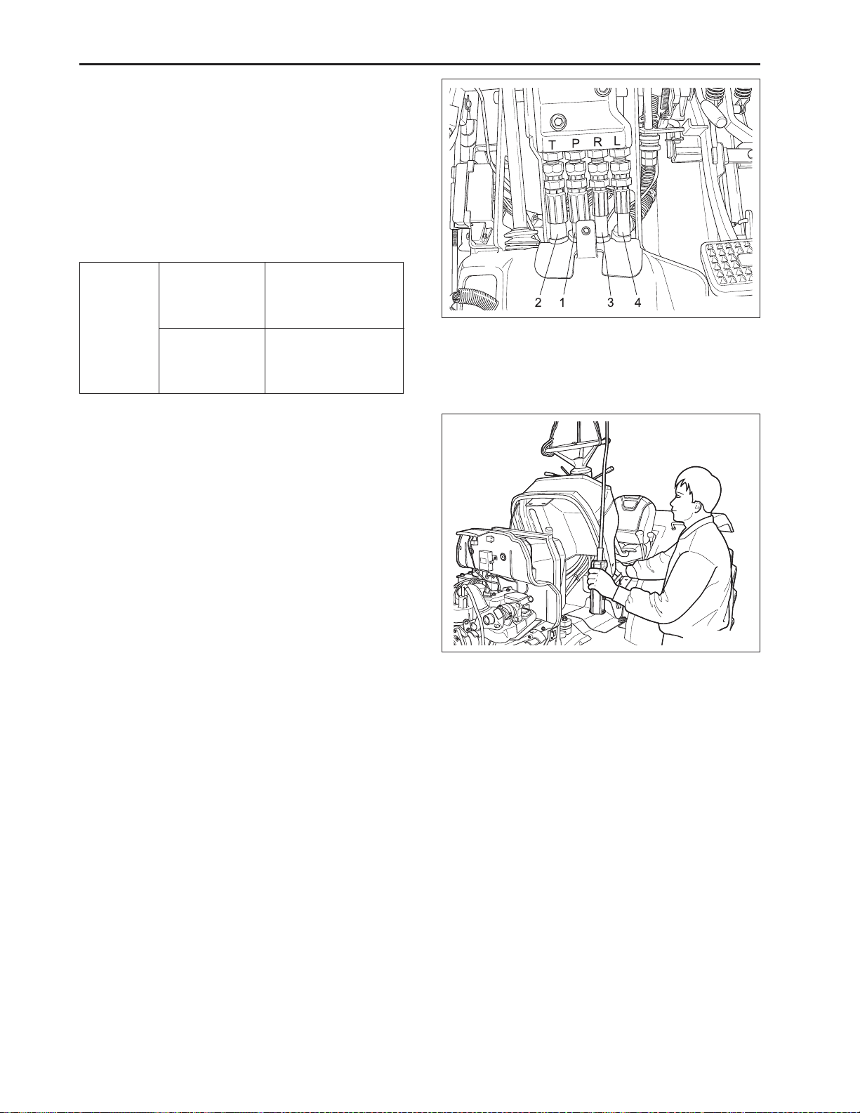
CHAPTER 3 8454
HYDRAULIC HOSES
1. Disconnect the main delivery hose (1), return hose
(2), right turning delivery hose (3) and left turning
delivery hose (4).
(When reassembling)
• In assembling the turning delivery hoses to the
steering controller, connect the delivery hose with
identification mark (type) “A” to the L port of the steering controller.
Tightening
torque
Main delivery
hose retaining
nut
Turning delivery
hose retaining
nut
46.6 ~ 50.9 N·m
4.8 ~ 5.2 kgf·m
34.4 ~ 37.6 lbf·ft
24.5 ~ 29.4 N·m
2.5 ~ 3.0 kgf·m
18.1 ~ 21.7 lbf·ft
PANEL FRAME AND STEERING ASSEMBLY
1. Remove the panel frame mounting crews (Two
screws a upper part. Seven screws at lower part).
2. Take out the panel frame and steering assembly as
a unit.
(When reassembling)
• Do not get in the wiring harness between panel
frame and platform.
569W307A
(1) Steering Hose P (3) Steering Hose R
(2) Steering Hose T (4) Steering Hose L
569W308A
3-8
D569-W02 May-2003
Page 99

4.2 SEPARATING ENGINE AND
CLUTCH HOUSING CASE
PROPELLER SHAFT
1. Slide the propeller shaft covers (4), (5) after remov-
ing to bolt (9).
2. Tap out the spring pin (10), and then slide the cou-
pling (2) the front.
(When reassembling)
• Apply grease to the splines of the propeller shaft.
CLUTCH
569W310A
(1) Propeller Shaft (6) O-Ring
(2) Coupling (7) O-Ring
(3) Cir-Clip (8) O-Ring
(4) Propeller Shaft Cover (9) Bolt
(5) Propeller Shaft Cover (10) Spring Pin
HYDRAULIC PIPES
1. Remove the brake rod (4) and suction pipe (3).
2. Remove the rubber hose (2).
3. Slide the return hose (1).
(When reassembling)
• Reinstall the pipe clamp securely.
Tightening
torque
Joint bolt for
delivery pipe (3)
and hydraulic
block
Joint bolt for
delivery pipe (2)
49.0 ~ 58.8 N·m
5.0 ~ 6.0 kgf·m
36.2 ~ 43.4 lbf·ft
34.3 ~ 39.2 N·m
3.5 ~ 4.0 kgf·m
25.3 ~ 28.9 lbf·ft
569W311A
(1) Return hose (3) Suction Pipe
(2) Rubber Hose (4) Brake Rod
D569-W02 May-2003
3-9
Page 100

CHAPTER 3 8454
SEP ARA TION THE ENGINE FROM CLUTCH
HOUSING
1. Place the jack under the clutch housing case.
2. Hoist the engine by the nylon lift strap at the tank
support.
3. Remove the engine mounting screws, and then pull
the engine to the front.
(When reassembling)
1. Apply grease to the splines.
2. Apply liquid gasket (Three Bond 1,208D or
equivalent) to joint face of the engine and clutch
housing.
569W312A
Tightening
torque
Engine and clutch
housing
mounting
screws, nuts
Engine and clutch
housing
mounting
stud bolts
77.5 ~ 90.2 N·m
7.9 ~ 9.2 kgf·m
57.1 ~ 66.5 lbf·ft
39.2 ~ 49.0 N·m
4.0 ~ 5.0 kgf·m
28.9 ~ 36.2 lbf·ft
4.3 DISASSEMBLY
A. Insert clutch center guide (1) up to the spline hub
and fix it not to be come off even though clutch inlet
bolt (2) is removed.
B. Remove clutch inlet bolts (2) and separate clutch
cover assembly (4).
• When attaching or detaching clutch,
slowly remove and slowly tighten the
clutch inlet bolts diagonally to secure
CAUTION
ASSEMBLY
A. Thoroughly remove worn dust attached on clutch
cover (4), clutch disc (5) and flywheel (3).
B. Insert clutch center guide (1) into the flywheel and
then fix.
C. When assembling clutch disc, face the shorter
spline boss toward flywheel side.
D. Tighten the clutch cover with bolts after confirming
the locations of lock pin holes (2 places).
operational safety and to prevent deformation of the clutch cover and
clutch pressure plate.
569W320A
Tightening
torque
(1) Clutch Center Guide (4) Clutch Cover
(2) Bolt (5) Clutch Disc
(3) Flywheel ( 6) Straight Pin
Clutch cover
assembling
bolts
23.5 ~ 27.5 N·m
2.4 ~ 2.8 kgf·m
17.4 ~ 20.3 lbf·ft
3-10
569W313A
D569-W02 May-2003
 Loading...