

Page 1
Operator’s Manual
826 SWE
1130 SWE
IMPORTANT: Read safety rules and instructions carefully before operating equipment.
Warning:
covered, brush-covered or grass-covered land unless the engine’s exhaust system is equipped with a spark arrester meeting
applicable local or state laws (if any). If a spark arrester is used, it should be maintained in effective working order by the operator.
In the State of California the above is required by law (Section 4442 of the California Public Resources Code). Other states may have
similar laws. Federal laws apply on federal lands. A spark arrester for the muffler is available through your nearest engine authorized
service dealer or contact the service department, P.O. Box 368023 Cleveland, Ohio 44136-9722.
This unit is equipped with an internal combustion engine and should not be used on or near any unimproved forest-
CUB CADET CORP. P.O. BOX 368023 CLEVELAND, OHIO 44136-9722
PRINTED IN U.S.A.
FORM NO.
770-10026A
(12/99)
Page 2
TABLE OF CONTENTS
Content Page
Important Safe Operation Practices...................................................................3
Loose Parts........................................................................................................5
Assembling Your Snow Thrower........................................................................5
Know Your Snow Thrower .................................................................................7
Operating Your Snow Thrower...........................................................................8
Making Adjustments ..........................................................................................10
Maintaining Your Snow Thrower........................................................................11
Service...............................................................................................................12
Troubleshooting.................................................................................................15
Parts List............................................................................................................16
FINDING MODEL NUMBER
This Operator’s Manual is an important part of your new snow thrower. It will help you assemble, prepare
and maintain the unit for best performance. Please read and understand what it says.
Before you start assembling your new equipment, please locate the model plate on the
equipment and copy the information from it in the space provided below. The information on
the model plat e is very import ant if you ne ed help fr om your loca l authorize d Cub Cade t
dealer.
You can locate the model number by looking at the lower frame cover on the rear of your snow thrower. A
sample model plate is explained below. For future reference, please copy the model number and the serial
number of the equipment in the space below.
(Model Number) (Serial Number)
Copy the model number here:
Copy the serial number here:
CUB CADET CORP.
P.O. BOX 368023
CLEVELAND, OHIO 44136
CALLING WARRANTY SERVICE
If you have difficulty assembling this product or have any questions regarding the controls, operation or
maintenance of this unit, please call the Customer Dealer Referral Line.
Call 1-(800)-528-1009 to locate your nearest Cub Cadet dealer. Before contacting your local
dealer, be sure to have your unit’s model number and serial number ready. See previous
section to locate this information.
2
Page 3

SECTION 1: IMPORTANT SAFE OPERATION PRACTICES
This Warning symbol points out important safety instructions which, if not followed, could endanger the
personal safety and/or property of yourself and/or others. Read and follow all instructions in this manual
before attempting to operate your snow thrower. Failure to comply with these instructions may result in
personal injury. When you see this symbol, heed its warning.
WARNING: The engine exhaust from this product contains chemicals known to the State of
California to cause cancer, birth defects, or other reproductive harm.
DANGER: Your snow thrower was built to be operated according to the rules for safe operation in this
manual. As with any type of power equipment, carelessness or error on the part of the operator can
result in serious in jury. Fail ure to obse rve the foll owing sa fety instru ctions coul d result in ser ious injur y
or death.
Training
• Read this operators manual carefully in its entirety
before attempting to assemble or operate this
machine. Be completely familiar with the controls
and the proper use of this machine before operating
it. Keep this manual in a safe place for future and
regular reference and for ordering replacement
parts.
• Never allow children under 14 years old to operate
a snow thrower. Children 14 years old and over
should only operate snow thrower under close
parental supervision. Only persons well acquainted
with these rules of safe operation should be allowed
to use your snow thrower.
• No one should operate this unit while intoxicated or
while taking medication that impairs the senses or
reactions.
• Keep the area of operation clear of all persons,
especially small children and pets.
• Exercise caution to avoid slipping or falling,
especially when operating in reverse.
Preparation
• Thoroughly inspect the area where the equipment is
to be used and remove all door mats, sleds, boards,
wires and other foreign objects.
• Disengage all clutches and shift into neutral before
starting the engine.
• Do not operate the equipment without wearing
adequate winter outer garments. Do not wear
jewelry, long scarfs or other loose clothing which
could become entangled in moving parts. Wear
footwear which will improve footing on slippery
surfaces.
• Before working with gasoline, extinguish all
cigarettes and other sources of ignition. Check the
fuel before starting the engine. Gasoline is an
extremely flammable fuel. Do not fill the gasoline
tank indoors, while the engine is running, or until
engine has been allowed to cool at least two
minutes. Replace the gasoline cap securely and
wipe off any spilled gasoline before starting the
engine as it may cause a fire or explosion.
• Use a grounded three wire plug-in for all units with
electric drive motors or electric starting motors.
• Adjust auger housing height to clear gravel or
crushed rock surface.
• Never attempt to make any adjustments while the
engine is running (except where specifically
recommended by the manufacturer).
• Let the engine and machine adjust to outdoor
temperature before starting to clear snow.
• Always wear safety glasses or eye shields during
operation or while performing an adjustment or
repair, to protect eyes from foreign objects that may
be thrown from the machine in any direction.
Operation
• Do not put hands or feet near or under rotating
parts. Keep clear of the discharge opening and
auger at all times.
• Exercise extreme caution when operating on or
crossing gravel drives, walks, or roads. Stay alert
for hidden hazards or traffic. Do not carry
passengers.
• After striking a foreign object, stop the engine,
remove wire from spark plug, and thoroughly
inspect the snow thrower for any damage. Repair
the damage before restarting and operating the
snow thrower.
• If the snow thrower should start to vibrate
abnormally, stop the engine and check immediately
for the cause. Vibration is generally a warning of
trouble.
• Stop engine whenever you leave the operating
position, before unclogging the collector/impeller
housing or discharge guide, and making any
repairs, adjustments, or inspections. Never place
your hand in the discharge or collector openings.
Use a stick or wooden broom handle to unclog the
discharge opening.
3
Page 4
• Take all possible precautions when leaving the unit
unattended. Disengage the collector/impeller, shift
into neutral, stop the engine, and remove the key.
• When cleaning, repairing, or inspecting, make
certain collector/impeller and all moving parts have
stopped. Disconnect the spark plug wire and keep
away from the plug to prevent accidental starting.
• Do not run an engine indoors. When starting the
engine and transporting the snow thrower in or out
of a building, open the doors. Exhaust fumes are
dangerous.
• Do not clear snow across the face of slopes.
Exercise extreme caution when changing direction
on slopes. Do not attempt to clear steep slopes.
• Never operate the snow thrower without guards,
plates, or other safety protection devices in place.
• Never operate the snow thrower near glass
enclosures, automobiles, window wells, drop off,
etc., without proper adjustments of snow thrower
discharge angle. Keep children and pets away.
• Do not overload the machine capacity by attempting
to clear snow at too fast a rate.
• Never operate the machine at high transport speeds
on slippery surfaces. Look behind and use care
when backing.
• Never direct discharge at bystanders or allow
anyone in front of unit.
• Disengage power to collector/impeller when
transporting or not in use.
• Use only attachments and accessories approved by
the manufacturer of snow thrower (such as wheel
weights, counter weights, cabs, etc.).
• Never operate the snow thrower without good
visibility or light. Always be sure of your footing an d
keep a firm hold on the handles. Walk, never run.
• The muffler and engine become hot and can cause
a burn. Do not touch these areas.
Maintenance And Storage
• Check the shear bolts, engine mounting bolts , etc.,
at frequent intervals for proper tightness to be sure
the equipment is in safe working condition.
• Never store the machine with fuel in the fuel tank
inside a building where ignition sources are present,
such as hot water and space heaters, clothes
dryers, and the like. Allow the engine to cool before
storing in any enclosure.
• Always refer to the operators manual instructions
for important details if the snow thrower is to be
stored for an extended period.
• Run the machine a few minutes after throwing snow
to prevent freeze up of collector/impeller. Check
clutch controls periodically to verify that they
engage and disengage properly and readjust if
necessary. Refer to the operators manual for
adjustment instructions.
Y our Responsibility
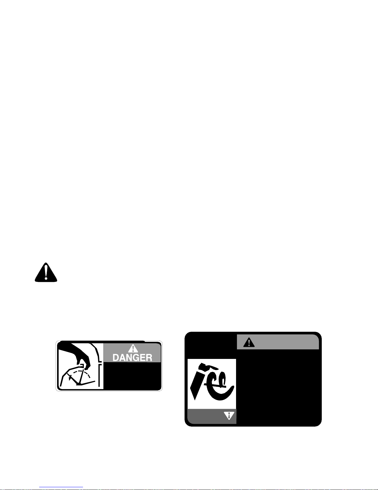
Restrict the use of this power machine to persons who read, understand and follow the warnings and
instructions in this manual and on the machine. Some of the safety labels on the equipment are
reproduced below. Take a moment to study these labels before operating the unit. Always maintain
safety while operating or servicing the equipment.
AND CLOTHING AWAY.
KEEP HANDS, FEET
ROTATING AUGER AVOID INJ U R Y FR O M
SHUT OFF ENGINE
BEFORE
UNCLOGGING
DISCHARGE CHUTE.
DANGER
WARNING
STOP ENGINE BEFORE REMOVING
1.
DEBRIS AND SERVICING UNIT.
KEEP CLEAR OF IMPELLER WHILE
2.
ENGINE IS RUNNING.
3.
NEVER DIRECT DISCHARGE AT
BYSTANDERS OR WINDOWS OR
ALLOW ANYONE IN FRONT OF
UNIT.
THOROUGHLY INSPECT THE AREA
4.
WHERE THE EQUIPMENT IS TO BE
USED AND REMOVE ALL DOOR
MATS, SLEDS, BOARDS, WIRES AND
OTHER FOREIGN OBJECTS.
REFER TO OWNERS MANUAL FOR
5.
FULL INSTRUCTIONS.
4
Page 5
SECTION 2: LOOSE PARTS
The snow thrower is shipped with the following loose parts in the carton. Please remove all loose parts from the
carton before discarding it. See Figure 1 to identify the parts, noting that these parts may be referred to again in the
following sections of the manual. Part numbers are shown in parentheses.
Auger Shear Bolts
Shear Bolts
(710-0890A)
Hex Lock Nuts
(712-0429)
The augers are secured to the auger shaft with two shear bolts and
hex lock nuts. If you hit a foreign object or ice jam, the snow thrower
is designed so that the bolts may shear. Two replacement shear
bolts and nuts ar e provid ed for your conveni ence. Sto re in a safe
place until needed.
IMPORTANT: NEVER replace the auger shear bolts with standard
hex bolts. Any damage to the auger gearbox or other components
as a result of doing so will NOT be covered by your snow thrower’s
warranty.
Figure 1
SECTION 3: ASSEMBLING YOUR SNOW THROWER
NOTE: Any referen ce in this manual to the left or right
side of the snow thrower is observed from the
operator’s position.
IMPORTANT: Make any final adjustments as instructed
later on in this section BEFORE operating your snow
thrower. Failure to follow the instructions may cause
damage to the snow thrower.
• Remove the screws from the top, sides, and ends
of the shipping carton.
• Set the panels aside to avoid tire punctures or
personal injury.
• Remove and discard the plastic bag that covers the
unit.
• Roll the unit out of the carton.
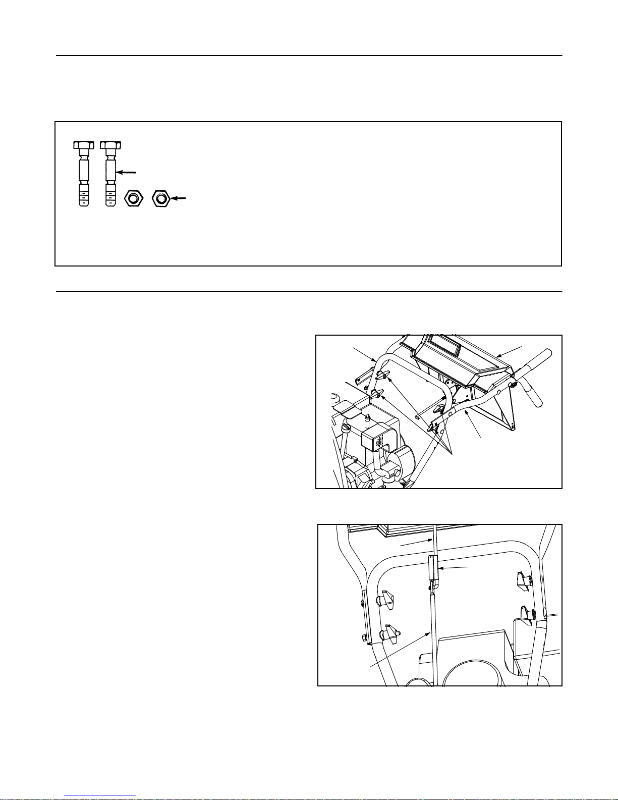
• Remove the lower two plastic wing nuts, cupped
washers and carriage bolts from each side of the
lower handle. See Figure 2.
• Raise the upper handle assembly until it locks over
the lower handle. See Figure 3.
• Look at the lower rear of the snow thrower frame to
be sure all the cables are aligned with the cable
roller guides.
• Secure the upper handle and lower handle with the
two plastic wing nuts, cupped washers and carriage
bolts previously removed and tighten the upper two
plastic wing nuts.
• Slide the shift rod connector down over the end of
the lower shift rod. See Figure 3. Tap the connector
until it locks over the lower shift rod.
Lower Handle
Wing Nuts,
Washers
and Bolts
Figure 2
Upper
Shift Rod
Connector
Lower
Shift Rod
Figure 3
NOTE: If the conn ector is not prop erly assemb led, the
shift rod will pivot and y ou will not be able to change
speeds or change directions.
Handle Panel
Upper Handle
Shift Rod
5
Page 6
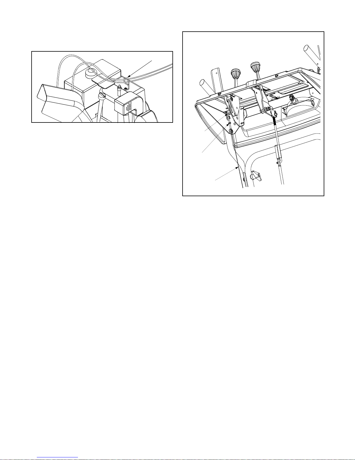
• If not already attached, slip the cables that run from
the handle panel to the chute into the cable guide
located on top of the engine. See Figure 4.
Cable Guide
Figure 4
Final Adjustments
“Z” End
Auger Control Adjustment
Check the adjustment of the auger control as follows:
• Push forward on the auger control (Refer to Figure
7) until the small rubber bumper contacts the upper
handle. There should be slack in the cable. See
Figure 5.
• Release the auger control. The cable should be
straight. Make certain you can depress the auger
control against the left handle completely without
using excess force.
If adjustment is necessary, proceed as follows:
• Loosen the jam nut and thread the cable in (for less
slack) or out (for more slack) as necessary. See
Figure 5.
• Recheck th e adjustm ent bef ore reti ghtenin g the
jam nut against the cable.
Traction Control and Shift Lever Adjustment
To check the adjustment of the traction control and shift
lever, proceed as follows:
• Move the shift lever into the sixth (6) position.
a. With the traction control (see Figure 7)
released, push the snow thrower forward,
then pull it back. Disregarding the overall
weight of the snow thrower, the machine
should otherwise move freely.
b. Engage the traction control, and attempt to
move the machine both forward and
rearward. You should experience resistance
as the wheels should not be turning.
• Move the shift lever into the fast reverse (R2)
position and repeat the previous steps (a & b).
If you experienced resistance either when repositioning
the shift lever (see Figure 7) from position 6 to R2 or
when attempting to move the machine forward or
rearward with the traction control released, your snow
thrower’s traction control is in need of adjustment and
you should NOT operate the snow thrower before
completing the adjustment as follows:
Jam Nut
Auger Control Cable
Figure 5
• Loosen the jam nut on the traction control cable
(located opposite the auger control cable) and
UNTHREAD the cable one full turn.
• Recheck t he ad justm ent.
• Retighten the jam nut to secure the cable when the
correct adjustment is reached.
If the machine can be moved freely both forward and
rearward with the traction control fully depressed,
proceed as follows:
• Loosen the jam nut on the traction drive cable and
THREAD the cable in one full turn.
• Recheck the adjustment and repeat the adjustment
as necessary.
• Retighten the jam nut to secure the cable when the
correct adjustment is reached.
NOTE: If y ou are unc ertain that you have reached the
correct adjustment, refer to the Traction Control
Adjustment in Section 6 of this manual.
Skid Shoe Adjustment
The space between the shave plate and the ground can
be adjusted by repositioning the skid shoes found on
either side of the snow throwers auger housing. For
smooth surface snow removal such as on an asphalt
driveway, place the skid shoes in a lower position. Use
a higher position when the area to be cleared is
uneven. See Figure 6.
IMPORTANT: When operating your snow thrower on a
gravel driveway, ALWAYS adjust the skid shoes into
the HIGHEST position.
6
Page 7
Adjust skid shoes as follows:
• Loosen, but do NOT remove, the three hex nuts
which fasten the skid shoe to the auger housing.
• Move the skid shoe to the desired position.
NOTE: Make certain the entire bottom surface of the
skidshoe is against the ground to avoid uneven wear on
the skid shoes.
• Retighten the hex nuts loosened earlier.
• Repeat this adjustment on the skid shoe found on
the opposite side of the snow thrower.
NOTE: The skid shoes are reversible on this machine.
When one side wea rs out, it can be rotated 180° and
the other flat skid surface can be used.
Carriage Bolts
Skid Shoes
SECTION 4: KNOW YOUR SNOW THROWER
Shave Plate
High
Low
Figure 6
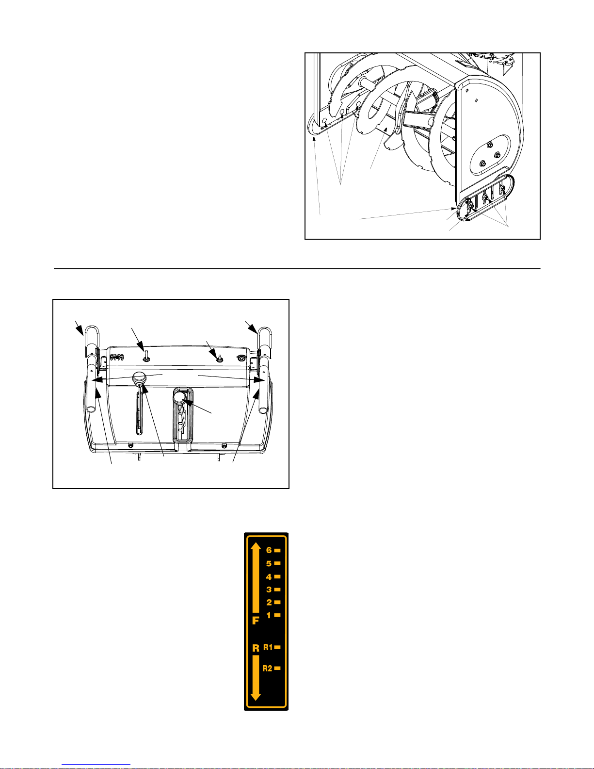
Hex Nuts
Auger
Control
Steering Control
Chute-Rotation
Left Wheel
Electric
Switch
Heated Handles
Handles
Chute
Tilt
Control
Figure 7
Traction Control /
Auger Control Lock
Switch
Shift
Lever
Right Wheel
Steering Control
Shift Lever
The shift lever is located in the center of the
handle panel and is used to determine both
ground speed and direction of travel. It can
be moved into any of eight positions.
Forward
Your snow thrower has six forward (F)
speeds. Position one (1) is the slowest and
position six (6) is the fastest.
Reverse
Your snow thrower has two reverse (R)
speeds. R1 and R2, R2 is the faster speed.
IMPORTANT: Always release the traction
control before changing speeds.
Auger Control
The auger control is located on the left handle. See
Figure 7. Squeeze the auger control lever to engage
the augers. Release to stop the snow throwing action
(the traction control must also be released).
Traction Contr ol / Auger Control Lock
The traction control is located on the right handle. See
Figure 7. Squeeze the traction control to engage the
wheel drive. Release to stop.
This same lever also locks the auger control so you
can operate the electric chute rotation switch without
interrupting the snow throwing process. If the auger
control is engaged simultaneously with the traction
control, the operator ca n release the auger control ( on
the left handle) and the augers will remain engaged.
Release the traction control to stop the augers and
wheel drive (the auger control must also be released).
Electric Chute-Rotation Switch
The electric chute-rotation switch is located o n the left
side of the snow thrower handle panel.
To change the direction in which discharged snow is
thrown, proceed as follows:
• Push the toggle switch to the left to rotate the chute
counterclockwise.
• Push the toggle switch to the right to rotate the
chute clockwise.
IMPORTANT: Release the switch once the chute has
completed its rotation cycle in either direction. Failure to
do so can result in damage to the electric chute motor
and/or its drive gear.
7
Page 8
Wheel Steering Controls
The left and right wheel steering controls are located on
the underside of the handles and are used to assist in
steering the snow thrower. See Figure 7. Squeeze the
right wheel steering control when turning right, squeeze
the left control when turning left. Operate your snow
thrower in open areas until you become familiar with
these controls.
NOTE: It is easier to maneuver a non-running snow
thrower with both wheel steering controls held in
simultaneously.
the Open (vertical) position before attempting to start
the engine.
Primer
Choke
Switch
Box
Heated Handles Switch
The heated handles switch is located on the right side
of the snow thrower handle panel. See Figure 7. To
activate the heated handles, toggle the switch to the
right to generate heat within the handles.
NOTE: The heated handles a re a compliment, NO T a
substitute for proper cold weather outerwear for hands.
It is recommended that the user wear gloves/mittens
when operating this snow thrower.
IMPORTANT: Toggle the heated handles switch to the
left into the OFF position after using the snow thrower.
Chute Tilt Contro l
The distance snow is thrown can be changed by
adjusting the angle of the chute assembly. Move the
chute tilt control forward to decrease the distance,
toward the rear to increase. See Figure 7.
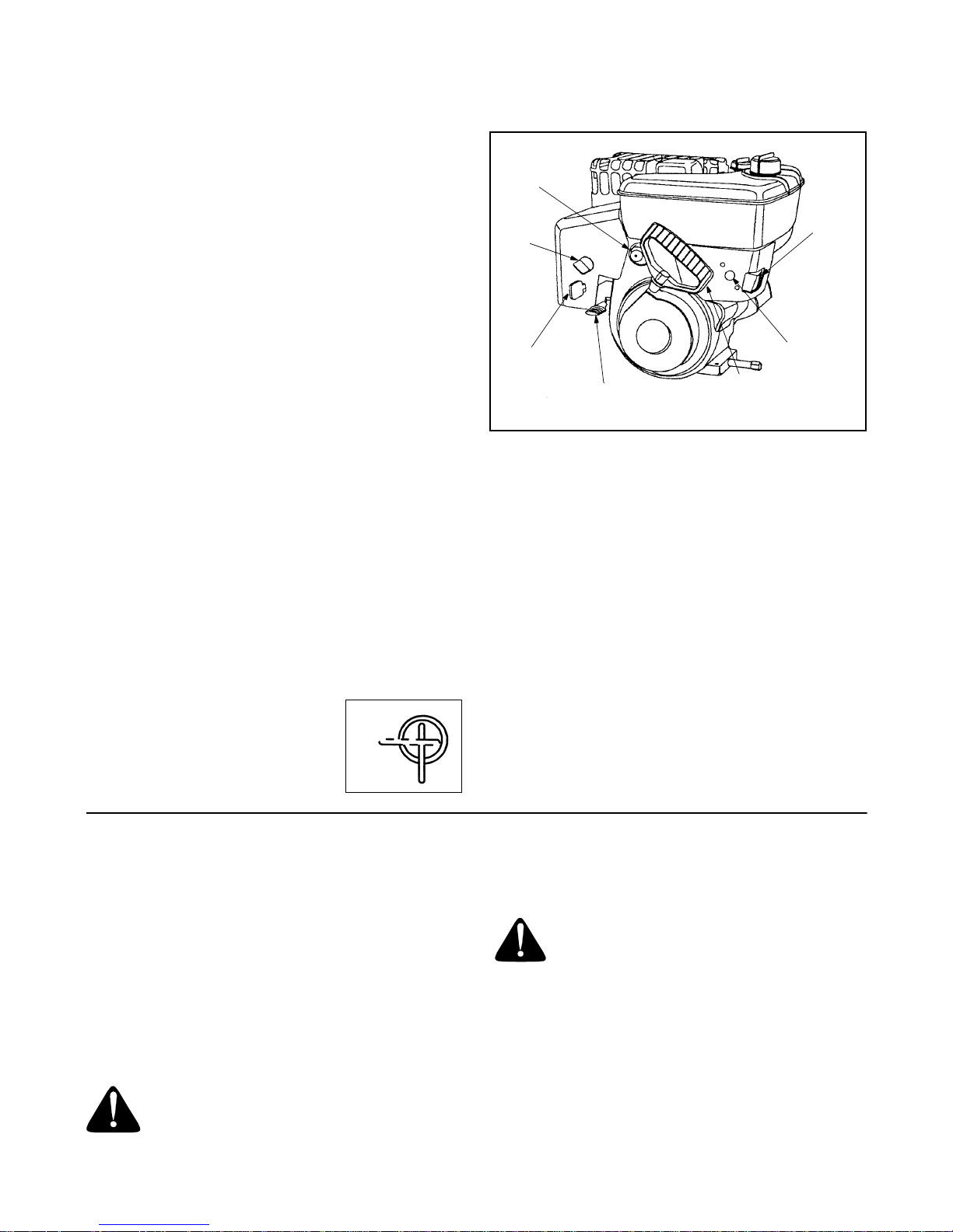
Fuel Shut-Off Valve
The fuel shut-off valve, located under
the fuel tank, controls fuel flow from
the tank. Always make certain it is in
Closed
Open
Electric
Ignition
Key
Throttle
Control
Recoil
Starter
Handle
Figure 8
Starter
Button
Headlight
The headlight is on whenever the engine is running.
Throttle Control
The throttle control is located on the engine. It regulates
the speed of the engine and will shut off the engine
when pushed down completely. See Figure 8.
Safety Ignition Key
The safety ignition key must be fully inserted in the
switch before the unit will start. Remove the ignition key
when the snow thrower is not in use. See Figure 8.
IMPORTANT: Do NOT attempt to turn the key.
SECTION 5: OPERATING YOUR SNOW THROWER
Gas And Oil Fill-Up
IMPORTANT: Although your snow thrower comes
shipped with oil already in the engine, you MUST check
the engine oil level as instructed in the separate engine
manual packed with your unit BEFORE starting the
engine for the first time. Read instructions carefully.
Service the engine with gasoline and oil as
instructed in the separate engine manual packed with
your snow thrower. Read instructions carefully.
WARNING: Never fill fuel tank indoors,
with the engine running or while engine is
hot. Do not smoke when filling fuel tank.
Electric Starter
WARNING: The electric starter is
equipped with a three-wire power cord
and plug, and is designed to operate on
120 volt AC household current. It must be properly
grounded at all times to avoid the possibility of
electric shock which may cause injury to the
operator. Follow all instructions carefully.
Determine that your house wiring is a three-wire
grounded system. Ask a licensed electrician if you
are not certain. If your house wiring system is not a
three-wire grounded system, do not use this
electric starter under any conditions. If your system
8
Page 9

is grounded and a three-hole receptacle is not
available at the point your starter will norma lly be
used, one should be installed by a licensed
electrician.
When connecting the power cord, always connect the
cord to the starter on the engine first, then plug the
other end into a three-hole grounded receptacle.
When disconnecting the power cord, always unplug the
end from the three-hole grounded receptacle first.
To Start Engine
IMPORTANT: If the unit shows any sign of motion
(traction drive or augers) with the controls disengaged,
shut the engine off immediately. Readjust as instructed
under Final Adjustments in Section 3 of this manual.
• Attach the spark plug wire to the spark plug.
• Make certain the fuel shut-off valve is in the open
(vertical) position.
• Make certain that both the auger control and the
traction control are in the disengaged position.
• Move the throttle control up to the FAST position.
Insert the ignition key into the slot. See Figure 8. Be
certain it snaps into place. Do not turn the key.
• Rotate the choke knob to the FULL choke position
(cold engine start). If the engine is warm, place the
choke in the OFF position.
• Connect the power cord (electric start) to the switch
box on the engine. Plug the other end of power cord
into a three-hole, grounded 120 volt AC receptacle.
• Push the primer button three times. If the engine is
warm, push the primer button once only. See
Figure 8.
NOTE: Always cover the ven t hole in the primer button
when pushing. Additional priming may be necessary for
°
cold starts if the temperature is below 15
• Electric Start: Push the starter button on the front
of the engine to turn the starter. When the engine
starts, release the starter button (see Figure 8).
• Recoil Start: Grasp the starter handle (see Figure
8) and pull the rope out slowly until resistance is
felt. Pull the starter handle rapidly. Do not allow the
handle to snap back. Allow it to rewind slowly while
keeping a firm hold on the starter handle.
• As the engine warms up and begins to operate
evenly, rotate the choke knob slowly to the OFF
position. If the engine falters, return to FULL choke,
then slowly move to the OFF position.
F.
To Stop Engine
• Run the engine for a few minutes after throwing
snow, to help dry off any moisture on the engine.
• To help prevent possible freeze-up of the starter,
proceed as follows:
Electric Starter: Connect the power cord to the
switch box on the engine, then connect to a 120
volt AC receptacle. With the engine running, push
the starter button and spin the starter for several
seconds. The unusual sound made by the spinning
starter will not harm the engine or starter. Disconnect the power cord from receptacle first, and then
from the switch box.
Recoil Starter: With the engine running, pull the
starter rope with a rapid, continuous full arm stroke
three or four times. Pulling the starter rope will produce a clattering sound, which is not harmful to the
engine or the recoil starter.
• To stop the engine, push the throttle control lever
down to the stop position. Remove the ignition key
by pulling it straight out of the keyhole and
disconnect the spark plug wire from the spark plug
to prevent accidental starting while the equipment
is unattended.
NOTE: Do not lose the i gnition key. Keep it in a safe
place. The engine will not start without the ignition key.
• Wipe all snow and moisture from the carburetor
cover in the area of the control levers. Also, move
the control levers back and forth several times.
Leave the throttle control lever in the STOP or OFF
position. Leave the choke control in the FULL
choke position. See Figure 8.
To Engage Wheel Drive
• With the engine running near top speed, move the
shift lever into one of the six FORWARD positions
or two REVERSE positions. Select a speed
appropriate for the snow conditions that exist.
NOTE: Use slower speeds in higher snow, and until
you are familiar with the operation of the snow thrower.
• Squeeze the traction control against the right
handle and the snow thrower will move. Release it
and the drive motion will stop.
IMPORTANT: NEVER move the shift lever without first
releasing the traction control. Doing so will cause
premature wear to the drive system’s friction wheel.
To Engage Augers
To engage the augers and start the snow throwing
action, proceed as follows:
• Squeeze the auger control against the left handle.
To disengage power to the augers:
• Release both the auger control and the traction
control, if engaged.
The auger control can be locked so you can turn the
electric chute directional control without interrupting the
snow throwing process. Refer to Traction Control/
Auger Control Lock in Section 4 of this manual.
9
Page 10

Operating Tips
NOTE: Allow the engine t o w ar m u p f or a few mi nut es .
The engine will not develop full power until it reach es
operating temperature.
WARNING: The temperature of the
muffler and the surrounding areas may
exceed 150
• For the most efficient snow removal, remove snow
immediately after it falls.
°
F. Avoid these areas.
SECTION 6: MAKING ADJUSTMENT
Sprocket
Hex Shaft
Axle Shaft
Drive Shaft
Chain
• Discharge the snow downwind whenever possible.
• Slightly overlap each previous path.
• Set the skid shoes 1/4" below the shave plate for
normal usage. The skid shoes may be adjusted
upward (to lo wer the sh ave plat e) for har d-packe d
snow. Adjust downward (to raise the shave plate)
when using on gravel or crushed rock.
• Be certain to follow the precautions found in the To
Stop Engi ne sec tion to pr even t possi ble freez e-up.
• Clean the snow thrower thoroughly after each use.
• Remove the frame cover underneath the snow
thrower by removing the six self-tapping screws.
• With the traction control released, there must be
clearance between the friction wheel and the drive
plate in all positions of the shift lever.
• With the traction control engaged, the friction wheel
must contact the drive plate. See Figure 9.
Drive Plate
Friction Wheel
Figure 9
WARNING: NEVER attempt to clean the
chute or make any adjustments while the
engine is running.
Skid Shoe Adjustment
The space between the shave plate and the ground can
be adjusted by raising or lowering the skid shoes. Refer
to Skid Shoe Adjustment in Section 3 of this manual.
Traction Control Adjustment
Refer to the information found under the heading Final
Adjustments in Section 3 of this manual to adjust the
traction control. If you are uncertain that you have
reached the correct adjustment, proceed as follows:
WARNING: Drain the gasoline out of your
snow thrower’s engine, or place a piece of
plastic film under the gas cap to avoid
spillage before making this adjustment.
Hairpin
Clip
Flat
Washer
Clutch Rod
Connector
Shift Arm
Figure 10
If adjustment is necessary:
• Loosen the jam nut on the traction drive cable
(Figure 5). Adjust the cable as necessary.
• Retighten the jam nut to secure the cable when
correct adjustment is reached and reassemble.
Shift Lever
Ferrule
Upper Shift Rod
Hairpin Clip
Lower Shift Rod
• Tip the snow thrower forward, allowing it to rest on
the auger housing.
NOTE: If you placed plas tic film unde r the gas ca p, be
certain to remove it before operating the snow thrower.
10
Page 11

Shift Rod Adjustment
To adjust the shift rod, proceed as follows.
• Remove the hairpin clip and slide the clutch rod
connector up, to separate the upper shift rod from
the lower shift rod. See Figure 10.
• Place the shift lever into the sixth (6) position.
• Rotate the shift arm clockwise (from the operator’s
position) as far as it will go.
• Thread the upper shift rod downward until the
elbow on its lower end aligns with the hole found in
the lower shift rod.
• Reconnect the upper shift rod to the lower shift rod
by reinserting the hairpin clip removed earlier and
sliding clutch rod connector back down into place.
IMPORTANT: Make certain to chec k for corre ct
adjustment of the shift rod as instructed under the
heading Final Adjustments in Section 3 of this manual,
before operating the snow thrower.
SECTION 7: MAINTAINING YOUR SNOW THROWER
Lubrication
WARNING: Disconnect the spark plug wire
and ground it against the engine before
performing any maintenance procedures.
Engine
Refer to the separate engine m anual p acked with yo ur
unit for all engine lubrication instructions.
WARNING: When following the
instructions in the separate engine manual
for draining oil, be sure to protect the
frame to avoid oil dripping onto
transmission parts.
Electric Chute-Rotation Motor
The gear on the electric chute-rotation motor and the
base of the discharge chute itself should be lubed with
multi-purpose automotive grease once a season. See
Figure 11.
Auger Shaft
At least once a season, remove the shear bolts on the
auger shaft. Spray lubricant inside the shaft. See Figure
12. Also lubricate the plastic auger bearings at least
once a season and grease the fittings on the end of the
auger shaft with a standard grease gun.
Hex Shaft
Lubricate the hex shaft with 6-n-1 grease at least once
a season or after every 25 hours of operation (available
at automotive stores, or order part number 737-0170).
Refer to Figure 9.
IMPORTANT: Keep all grease and oil off of the rubber
friction wheel and aluminum drive plate.
Drive and Shifting Mechanism
Lubricate at least once a season or after every 25 hours
of operation. Remove the frame cover, lubricate any
chains, sprockets, gears, bearings, shafts, and shifting
mechanism at least once a season. Use engine oil or a
spray lubricant. Avoid getting oil on the friction
wheel rubber and aluminum drive plate. Refer to
Figure 9.
Lube Gear
and Chute Base
Figure 11
Grease Fittings
Vent Plug
Shear Bolts
Plastic Be arings
Figure 12
Traction Cont rol / Auger Co ntrol Lock
The cams on the ends of the control rods which
interlock the traction drive and auger drive levers must
be lubricated at least once a season or every 25 hours
11
Page 12

of operation. The cams can be accessed beneath the
handle panel. Use a multi-purpose automotive grease.
Gear Case
The gear case is lubricated with grease at the factory.
Every 25 hours or once a season, remove the vent plug
located on the top of the gear case. If necessary, use a
grease gun on the gear case grease fitting. Lubricate
SECTION 8: SERVICE
using Shell Alvania grease EPR00, part number 737-
0168. Refer to Figure 12.
IMPORTANT: Do not overfill the gear case. Damage to
the seals could result. Be sure the vent plug is free of
grease in order to relieve pressure.
WARNING: Disconnect the spark plug wire
and ground it against the engine before
performing any repairs or maintenance.
Engine
Refer to the separate engine manual packed with your
unit for all engine maintenance procedures.
Augers/Shear Bolts
The augers are secured to the auger shaft with two
shear bolts and hex lock nuts. Refer to Figure 12. If you
hit a foreign object or ice jam, the snow thrower is
designed so that the bolts may shear.
If the augers will not turn, check to see if the bolts have
sheared. Two replacement shear bolts and hex lock
nuts have been provided with the snow thrower. For
future use, order kit number OEM-710-0890 which
contains four replacement shear bolts and
accompanyin g hex lock nuts.
IMPORTANT: NEVER replace the auger shear bolts with
standard hex bolts. Any damage to the auger gearbox
or other components as a result of doing so will NOT be
covered by your snow throwers warranty.
Shave Plate And Skid Shoes
The shave plate and skid shoes on the bottom of the
snow thro wer ar e subj ect to we ar. T hey sh ould be
checked periodically and replaced when necessary.
Refer to Figure 6.
To remove the skid shoes, remove the six carriage
bolts, belleville washers and hex nuts (three on each
side) which attach them to the snow thrower.
Reassemble the new skid shoes making sure that the
bolts and washers are reinstalled correctly. Also, make
certain the skid shoes are adjust ed so the fla t surface is
sitting level on the ground. The skid shoes can be
rotated on this machine 180° so both flat surfaces of the
skid shoe can be utilized for wear.
To remove the shave plate, remove the carriage bolts,
belleville washers and hex nuts which attach it to the
snow thrower housing. Reassemble the new shave
plate, making sure the heads of the carriage bolts are to
the inside of the housing. Tighten securely.
Belt Removal And Replacement
WARNING: Disconnect the spark plug wire
and ground it against the engine before
performing any repairs or maintenance.
Auger Belts
• Remove the plast ic bel t cove r at th e fro nt of the
engine by removing the two self-tapping screws.
See Figure 13.
• Drain the gasoline from the snow thrower, or place
a piece of plastic film under the gas cap.
• Tip the snow thrower up and forward so that it rests
on its auger housing.
Engine
Self-Tapping
Screws
Belt Cover
Auger Housing
Figure 13
• Remove the six self-tapping screws from the frame
cover underneath the snow thrower.
• Roll the front and rear auger belts off the auger
drive pulley. See Figure 14.
• Unhook the idler spring from the hex bolt on the
auger housing. See Figure 15.
• Back out the stop bolt until the support bracket
rests on the auger pulley. See Figure 16.
NOTE: It may be necessa ry to loosen the s ix nuts that
connect the frame to the auger housing to aid in belt
removal.
• Lift the rear auger belt from the auger pulley, and
slip the belt between the support bracket and the
auger pulley. See Figure 15. Repeat this step for
the front auger belt.
12
Page 13

• Replace both auger drive belts by following
instructions in reverse order.
Friction Wheel
Wheel
Drive
Pulley
Auger
Drive
Pulley
Idler
Pulley
Frame
Wheel
Drive
Belt
Idler
Pulley
Auger
Drive
Belts
Figure 14
NOTE: If you placed plas tic film unde r the gas cap, be
certain to remove it before operating the snow thrower.
Drive Belt
• Follow the first four steps of the instructions for
servicing the auger belts.
• Pull the idler pulley up, and lift the belt off the wheel
drive pulley and friction wheel disc. See Figure 15.
• Back out the stop bolt until the support bracket
rests on the auger pulley. See Figure 16.
• Slip the belt between the friction wheel and drive
disc. See Figure 16. Remove and replace the belt.
Reassemble following the instructions in reverse
order.
NOTE: The suppo rt bracket must rest on the stop bolt
after the new belt has been assembled. See Figure 16.
Drive Plate
Drive Belt
Stop Bolt
Support Bracket
Figure 16
Replacing Friction Wheel Rubb er
The rubber on the friction wheel is subject to wear and
should be checked after 25 hours of operation, and
periodically thereafter. Replace the friction wheel
rubber if any signs of wear or cracking are found.
• Drain the gasoline from the snow thrower, or place
a piece of plas tic under the gas cap.
• Tip the snow thrower up and forward, so that it rests
on the housing.
• Remove the six self-tapping screws from the frame
cover underneath the snow thrower.
• Remove the cli ck pin that secures t he lef t wheel to
the axle and slide the wheel from the axle.
• Remove the four screws securing the left drive
cover to the frame. Remove the drive cover. See
Figure 18.
Screws
Friction Wheel Rubber
Hub
Screws
Support
Bracket
Rear
Auger
Belt
Front
Auger
Belt
Auger
Pulley
Idler
Spring
Auger
Housing
Figure 15
Support
Bracket
Spring
Frame
Friction Wheel Plates
Figure 17
• Holding the friction wheel assembly, slide the hex
shaft out of the left side of the frame. See Figure 19.
The spacer on the right side of the hex shaft will fall
and the sprocket should remain hanging loose in
the chain.
• Lift the friction wheel assembly out between the
axle shaft and the drive shaft assemblies.
• Remove the six screws from the friction wheel
assembly (three from each side). Remove the
friction wheel rubber from between the friction
wheel plates. See Figure 17.
13
Page 14

• Reassemble the new friction wheel rubber to the
friction wheel plates and hub, tightening the six
screws in rotation and with equal force.
• Position the friction wheel assembly up onto the pin
of the shift rod assembly, and slide the hex shaft
through the friction wheel assembly. Reassemble
in reverse order.
NOTE: If you placed plas tic film unde r the gas cap, be
certain to remove it.
Drive
Cover
Screws
Left
Drive
Cover
Shift Rod Assy
Axle Shaft
Drive Shaft
Figure 19
Off-Season Storage
Pin
Hex Shaft
Friction
Wheel
Assembly
Figure 18
Frame
Cover
Left Axle
WARNING: Never store an engine wit h fuel
in the tank indoors or in poorly ventilated
areas, where fuel fumes may reach an open
flame, spark or pilot light as on a furnace,
water heater, clothes dryer or any gas
appliance.
• If the unit is to be stored for over 30 days, prepare
the engine for storage as instructed in the separate
engine manual packed with your unit.
• Remove all debris from the exterior of the engine
and equipment.
• Follow the lubrication recommendations found in
Section 7 of t his manua l.
• Always store the snow thrower in a clean, dry area.
NOTE: When storing any type of power equipment in
an unventilated or metal sto rage shed, care shou ld be
taken to rust proof the equipment. Using a ligh t oil or
silicone, coat the equipment, especially any chains,
springs, bearings and cables.
14
Page 15

SECTION 9: TROUBLESHOOTING
Problem Cause Remedy
Engine fails to start 1. Fuel tank empty, or stale fuel.
2. Blocked fuel line.
3. Choke not in the ON position
4. Faulty spark plug.
5. Safety key not in ignition switch on engine.
6. Spark plug wire disconnected.
7. Primer button not being used properly.
8. Fuel shut-off valve closed.
Engine runs erratic 1. Unit running on CHOKE.
2. Blocked fuel line or stale fuel.
3. Water or dirt in the fuel system.
Loss of power 1. Spark plug wire loose.
2. Gas cap vent hole plugged.
Excessive vibration 1. Loose parts or damaged auger. 1. Stop the engine immediately and
Unit fails
to propel itself
Unit fails
to discharge snow
Electric ch ute fails to
turn
Electric chute turns
in opposite direction
of the switch
Heated grips are not
creating heat
1. Traction control cable in need of
adjustment.
2. Drive belt loose or damaged.
1. Discharge chute clogged.
2. Shear bolt sheared.
3. Foreign object lodged in auger.
4. Auger control cable in need of adjustment.
5. Auger belt loose or damaged.
1. Loose electrical connections.
2. Blown Fuse.
1. The switch connector is installed
backwards
1. Loose electrical connections.
2. Blown fuse.
3. Faulty grip. If one heated grip fails, both
grips will not function.
1. Fill tank with clean, fresh gasoline. Fuel
becomes stale after thirty days.
2. Clean the fuel line.
3. Move switch to the ON position
4. Clean, adjust gap or replace.
5. Insert the key fully into the switch.
6. Connect spark plug wire.
7. Refer to the engine manual.
8. Open fuel shut-off valve.
1. Move the choke lever to OFF position.
2. Clean the fuel line; fill the tank with
clean, fresh gasoline.
3. Drain the fuel tank and carburetor.
Refill with fresh fuel.
1. Connect and tighten spark plug wire.
2. Remove ice and snow from gas cap. Be
certain vent hole is clear.
disconnect the spark plug wire. Tighten
all bolts and nuts. If vibration continues,
have the unit serviced by an authorized
service dealer.
1. Adjust traction control cable. Refer to
Section 6 of this manual.
2. Replace drive belt. Refer to Section 8 of
this manual.
1. Stop engine and disconnect spark plug
wire. Clean discharge chute and inside
of auger housing.
2. Replace shear bolt.
3. Stop engine immediately and
disconnect spark plug wire. Remove
object from auger.
4. Adjust auger control cable. Refer to
Section 6 of this manual.
5. Refer to Section 8 of this manual.
1. Make sure all connections are tight and
fully installed.
2. Replace 5A fuse. Located under handle
panel near switch connector.
1. Unplug the switch connector under the
handle panel. Turn connector 180° and
reconnect.
1. Under the handle panel, check
connections from the handles to the
wiring harness.
2. Replace 5A fuse under the handle
panel near crank switch connector.
3. Have the grips checked at an
authorized service dealer.
15
Page 16

SECTION 10: PARTS LIST
Models 826 SWE / 1130 SWE
1
2
3
Ref.
No.
1.
2.
3.
4.
5.
Part No. Part Description
734-1709
734-1712
738-0994A Axle: .75” dia. x 12.201” Lg.
734-1530
734-1525
734-1708
734-1711
734-0255 Tubeless Air Valve
NOTE: For painted parts, please refer to the list of
color codes below. Please add the applicable color
code, wherever needed, to the part number to order
a replacement part. For instance, if a part,
numbered 700-xxxx, is painted Cub Yellow, the part
number to order would be 700-xxxx-0498.
Wheel Assy Comp: 16.5” x 4.8” (826 SWE)
Wheel Assy Comp: 16” x 6.5” (1130 SWE)
Tire, Snow Hog, 16.5 x 4.8 - 4 (826 SWE)
Tire, Snow Hog, 16.0 x 6.5 x 8 (1130 SW E)
Rim Assembly (826 SWE)
Rim Assembly (1130 SWE)
Cub Yellow: 0498
Cub Beige: 0499
Powder Black: 0637
5
4
16
Page 17

Models 826 SWE / 1130 SWE
4
16
13
17
11
9
8
1
5
6
7
12
2
Ref.
No.
1.
2.
3.
4.
5.
6.
7.
8.
9.
10.
11.
12.
13.
14.
15.
16.
17.
18.
— 737-0168 Grease (Two Ounces)
Part No. Part Description
618-0123 RH Housing (Incl. Ref. 17, 18)
618-0418 LH Housing w/Fitting (Incl. Ref. 17, 18)
710-0642 Self Tapping Screw, 1/4-20 x .75
711-1024
711-0909
714-0161 Hi-Pro Key, 3/16 x 5/8
715-0143 Spring Spiral Pin, .25 x 1.25
717-0528 Worm Gear, 20-tooth
717-0526 Worm Shaft
718-0186 Thrust Collar
721-0325 Grease Plug
721-0327 Grease Seal
736-0351 Flat Washer, .76 x 1.5 x .030
736-0369 Flat Washer, .508 x 1.0 x .020
736-0445 Flat Washer, .76 x 1.5 x .060
741-0662 Flange Bearing, .75 x 1.0 x .59
741-0663 Flange Bearing, .503 ID x .75 OD
618-0417
618-0415
737-3000 Grease Fitting, 3/16” Drive
Spiral Axle, 30” (1130 SWE)
Spiral Axle, 26” (826 SWE)
Gear Assy Complete, 30” (1130 SWE)
Gear Assy Complete, 26” (826 SWE)
15
14
3
10
18
3
17
Page 18

Models 826 SWE / 1130 SWE
68
50
67
37
63
65
57
58
57
58
55
58
66
62
60
2
24
20
3
9
40
66
58
61
77
11
15
5
14
78
14
53
56
64
76
79
45
5
10
69
27
75
9
51
82
31
40
46
45
47
21
27
74
27
5
70
5
59
22
72
73
72
27
71
68
69
54
81
29
8
13
17
11
25
31
39
For
reference
only
38
23
32
26
43
11
18
15
52
16
41
30
42
6
For
reference
only
44
27
9
35
35
36
48
10
49
44
28
12
4
1
19
14
9
7
18
Page 19

Models 826 SWE / 1130 SWE
Ref.
No.
1.
2.
3.
4.
5.
6.
7.
8.
9.
10.
11.
12.
13.
14.
15.
16.
17.
18.
19.
20.
21.
22.
23.
24.
25.
26.
27.
28.
29.
30.
31.
32.
35.
36.
37.
38.
39.
40.
41.
42.
Part No. Part Description
684-0008A Shift Arm Assembly
710-0262 Carriage Bolt 5/16-18 x 1.5”
710-0449 Carriage Bolt 5/16-18 x 2.25”
710-0788 TT Screw 1/4-20 x 1”
710-0837 C-Sunk Screw #10-16x 0.625”
710-0890A Shear Bolt 5/16-18 x 1.5”
710-3008 Hex Screw 5/16-18 x .75”
711-0677 Ferrule
712-0429 Hex Lock Nut 5/16-18
712-3010 Hex Nut 5/16-18
714-0104 Cotter Pin
720-0284 Handle Knob
725-1757 Heated Grip
736-0242 Belleville Washer
736-0275 Flat Washer
736-0451 Saddle Washer
747-0620A Shift Rod: Upper
747-0621 Shift Rod: Lower
749-0951 Lower Handle
749-0952A Upper Handle: L S tyle RH
749-0953A Upper Handle: L S tyle L H
750-0963 Connector: Shift Rod
618-0419 Gear Assembly: Ring
629-0937 Electric Harness: Lower
710-0262 Carriage Bolt: 5/16-18 x 1.5”
710-0451 Carriage Bolt: 5.16-18 x .750”
710-0599 TT Screw: 1/4-20 x 0.5”
710-0602 TT Screw: 5/16-18 x 1”
710-0805 Hex Screw: 5/16-18 x 1.5”
710-0817 TT Screw: 5/16-18 x 1.25”
710-0896 Hex Screw AB:1/4-14 x 0.625”
710-3008 Hex Screw: 5/16-18 x .75”
712-3027 Hex Flange Lock Nut
724-0249 Electric Motor: Chute Crank
725-0157 Cable Tie
731-0851A Chute Flange Keeper
731-1300A Lower Chute
731-1313C Ca ble Guide: Chute Ti lt
731-1320 Upper Chute
731-2279 Motor Cover: Chute Rotation
Ref.
No.
43.
44.
45.
46.
47.
48.
49.
50.
51.
52.
53.
54.
55.
56.
57.
58.
59.
60.
61.
62.
63.
64.
65.
66.
67.
68.
69.
70.
71.
72.
73.
74.
75.
76.
77.
78.
79.
80.
81.
82.
Part No. Part Description
736-0159 5/16 Washer
736-0242 Belleville Washer
736-0506 Special Washer
746-0896 Control Cable
746-0901 Control Cable
750-1232 Spacer
782-0599 Motor Bracket
784-5594 Cable Bracket
784-5604 Handle: Chute Tilt
629-0936 Harness Assembly: Upper
684-0036 Handle Assembly RH
684-0037 Handle Assembly LH
710-1003 Special Hex Screw
712-0271 Hex Sems Nut: 1/4-20
712-0693 Hex Nut
716-0398 Lock Ring: Toggle Switch
720-0232 Shift Knob
725-1672 Lamp Housing
725-1755 Toggle Switch: Double Throw
725-1756 Toggle Switch: Single Throw
725-1759 Halogen Lamp: 50W, 12V
726-0152 Mounting Clamp
731-2276 Handle Panel
736-0226 Flat Washer
747-1136 Headlight Retainer
714-0507 Cotter Pin: 3/32 x .75
747-0877 Cam Rod
784-5680 RH Handle Support Bracket
784-5679 LH Handle Support Bracket
748-0362 Cam Handle Lock
748-0363 Handle Lock Pawl
732-0145 Compression Spring: .36 x 1.0
710-0459A Hex Cap Screw: 3/8-24 x 1.5
784-5619A Shift Handle
712-0116 Jam Nut, 3/8-24
732-0193 Comp. Spring: .39 x .6 x .88
736-0105 Bell Washer
784-5682 RH Handle Support Bracket
784-5681 LH Handle Support Bracket
711-0653 Clevis Pin
19
Page 20

Models 826 SWE / 1130 SWE
38
18
34
2
3
4
11
10
15
14
27
28
9
13
35
12
13
25
10
9
16
23
22
26
30
19
1
5
6
7
8
21
23
22
39
40
42
37
18
36
41
39
29
16
20
31
32
33
17
40
24
20
Page 21

Models 826 SWE / 1130 SWE
Ref.
No.
1.
2.
3.
4.
5.
6.
7.
8.
9.
10.
11.
12.
13.
14.
15.
16.
17.
18.
19.
20.
21.
22.
Part No. Part Description
712-0116 Lock Jam Nut 3/8-24
756-0178 Flat Idler
784-5632A Auger Idler Arm
710-0459A Hex Cap Screw 3/8-24 x 1.50
738-0281 Shoulder Screw
736-0174 Wave Washer
732-0611 Extension Spring
712-3068 Hex Nut 5/16-18
710-0276 Carriage Bolt, 5/16-18 x 1.00
736-0119 Lock Washer 5/16
05931 Housing
741-0309 Ball Bearing
710-0451 Carriage Bolt, 5/16-18 x .75
705-5226 Chute Reinforcement
684-0055B
684-0040C
712-3010 Hex Nut 5/16-18
712-0429 Lock Nut 5/16-18
736-0242 Belleville Washer
736-0231 Flat Wshr, .344ID x 1.125 OD
737-3000 Grease Fitting, 3/16” Drive
731-1379A Chute Adapter
712-0324 Hex Lock Nut 1/4-20
30” Housing Assy (1130 SWE)
26” Housing Assy (826 SWE)
Ref.
No.
23.
24.
25.
26.
27.
28.
29.
30.
31.
32.
33.
34.
35.
36.
37.
38.
39.
40.
41.
42.
Part No. Part Description
736-0463 Flat Washer
784-0399 Bearing Housing w/Fitting
710-0703 Carriage Screw 1/4-20 x .75
710-0604 Hex Screw 5/16-18
736-0169 Lock Washer 3/8
712-0798 Hex Nut 3/8-16
741-0245 Hex Flange Bearing
784-5038B Skid Shoe
736-0242 Bell Washer
712-3010 Hex Nut 5/16-18
784-5575
784-5579A
710-0260 Carriage Bolt 5/16-18 x .62
684-0065 Impeller Assembly
715-0114 Pin
618-0417
618-0415
605-5248A
605-5192A
736-0188 Flat Washer
741-0493A Flange Bushing
605-5249A
605-5193A
710-0890A Shear Bolt 5/16-18 x 1.5
Shave Plate (1130 SWE)
Shave Plate (826 SWE)
30” Gear Assy (1130 SWE)
26” Gear Assy (826 SWE)
30” Spiral RH (1130 SWE)
26” Spiral RH (826 SWE)
30” Spiral LH (1130 SW E)
26” Spiral LH (826 SWE)
NOTE: For painted parts, please refer to the list of
color codes below. Please add the applicable color
code, wherever needed, to the part number to order
a replacement part. For instance, if a part,
numbered 700-xxxx, is painted Cub Yellow, the part
number to order would be 700-xxxx-0498.
Cub Yellow: 0498
Cub Beige: 0499
Powder Black: 0637
21
Page 22

Models 826 SWE / 1130 SWE
28
29
30
26
23
22
21
16
19
16
16
19
16
15
11
12
10
18
27
17
14
1
3
4
8
9
13
7
4
6
5
1
2
20
24
25
22
Page 23

Models 826 SWE / 1130 SWE
Ref.
No.
1.
2.
3.
4.
5.
6.
7.
8.
9.
10.
11.
12.
13.
14.
15.
16.
17.
18.
19.
20.
21.
22.
23.
24.
25.
26.
27.
28.
29.
30.
Part No. Part Description
710-1652 Hex Washer Screw 1/4-20 x .625
731-1324 Belt Cover
732-0710 Extension Spring
710-0627 Hex Screw 5/16-24 x .75
710-3005 Hex Cap Screw 3/8-16 x 1.25
05896A Drive Clutch Idler Brac ket
748-0234 Shoulder Spacer
756-0987 Pulley Half
754-0346 V-Belt
756-0986 Pulley Half
736-0270 Bell Washer
710-0230 Hex Cap Screw 1/4-28 x .50
756-0313 Flat Idler
710-1245 Lock Hex Cap Screw 5/16-24
712-0181 Lock Jam Nut 3/8-16
756-0569 Pulley Half
736-0242 Bell Washer
736-0505 Flat Washer
754-0430A Belt
756-0967 Auger Pulley
736-0247 Flat Washer 3/8 x 1.25 O D
736-0331 Bell Washer
710-0696 Hex Cap Screw 3/8-24
748-0360 Adapter Pulley
710-0654A Hex Screw 3/8-16 x 1.0
629-0071 Extension Cord
OEM-390-987 Electric Start Kit
712-0324 Lock Nut, 1/4-20
736-0173 Flat Washer, .28 x .74 x .063
732-0705 Cable Guide
23
Page 24

Models 826 SWE / 1130 SWE
54
42
11
29
16
30
7
26
49
11
41
47
36
43
31
34
22
9
16
30
9
14
21
43
9
9
23
44
27
13
51
28
14
9
21
4
22
34
11
26
55
57
47
32
17
11
34
18
40
19
36
5
14
21
39
9
45
24
50
6
52
40
34
32
18
34
37
33
7
14
32
20
38
46
34
37
33
25
8
3
20
32
48
10
35
53
38
1
13
7
Drive Clutch Cable
routed below axle
and hooked here
15
24
47
11
11
36
Page 25

Models 826 SWE / 1130 SWE
Ref.
No.
1.
2.
3.
4.
5.
6.
7.
8.
9.
10.
11.
12.
13.
14.
15.
16.
17.
18.
19.
20.
21.
22.
23.
24.
25.
26.
27.
28.
29.
Part No. Part Description
618-0043 Dogg Assembly: RH
618-0044 Dogg Assembly: LH
618-0303B Shift Assembly: Steerable Drive
656-0012A Friction Wheel Dis c Assy.
684-0014B Shift Rod Assembly
684-0042B Bearing
684-0130 Transmission F rame As sembly
684-0131A Support Bracket Assembl y
710-0599 Hex Wshr Hd. TT Screw 1/4-20 x .5
710-0788 Hex Wshr Hd. TT Screw 1/4-20 x 1
710-1652 Hex Hd TT Scrw 1/4-20 x .625”
711-1267 Drive Shaft
711-1268 Actuator Shaft
711-1364 Pin
712-0711 Jam Nut 3/8-24 Gr .8
712-3017 Hex Nut: 3/8-16
713-0233 Chain
713-0374 Chain
713-0413 Sprocket: 10T
713-0472 Sprocket
714-0104 Cotter Pin
736-0142 Flat Washer
714-0474 Cotter Pin
716-0102 Snap Ring
721-0263 Adhesive: Loctite
732-0209 Extension Spring
732-0264 Extension Spring
736-0105 Bell Washer
736-0160 Flat Washer
Ref.
No.
30.
31.
32.
33.
34.
35.
36.
37.
38.
39.
40.
41.
42.
43.
44.
45.
46.
47.
48.
49.
50.
51.
52.
53.
54.
55.
56.
57.
58.
Part No. Part Description
736-0169 Lock Washer
784-5740 Retainer Shaft LH: Actua tor Drive
736-0351 Flat Washer
736-0626 Flat Washer
737-0170 Lubricant: 6 in 1
737-3007 Grease
738-0924 Shoulder Screw
741-1111 Hex Flange Bearing
741-0598 Hex Flange Bearing
741-0600 Ball Bearing
741-0701 Flange Bushing
746-0897 Auger Clutch Cable
746-0898 Drive Clutch Cable
746-0956 Steering Cable
748-0190 Spacer
750-1161 Axle Support Tube
750-1162 Spacer
756-0625 Roller Cable
784-5590 Shift Bracket
784-5687A Auger Clutch Cable G uide Brac ket
784-5689A Front Support Guide Brac ket
784-5730A Retainer Shaft RH: Act uator Dri ve
784-5732 Frame Cover
784-5733 Roller Bracket: Drive Cable
710-1233 Oval C-Sunk Mach ine Screw
712-0127 Weld Nut
725-0157 Cable Tie
746-0950 Turn Trigger
714-0104 Cotter Pin
NOTE: For painted parts, please refer to the list of
color codes below. Please add the applicable color
code, wherever needed, to the part number to order
a replacement part. For instance, if a part,
numbered 700-xxxx, is painted Cub Yellow, the part
number to order would be 700-xxxx-0498.
Cub Yellow: 0498
Cub Beige: 0499
Powder Black: 0637
25
Page 26

Models 826 SWE / 1130 SWE
26
Page 27

Models 826 SWE / 1130 SWE
Optional Equipment
Drift Cutters- Part Number:OEM-390-679
Tire Chains- Part Number:OEM-390-991 (826 SWE)
Part Number:OEM-390-655 (1130 SWE)
27
Page 28

MANUFACTURER’S LIMITED WARRANTY FOR:
TWO-YEAR RESIDENTIAL
ONE-YEAR COMMERCIAL
Proper maintenance of your Cub Cad et equi pm ent is the own er’s responsibility. Follow the instructions in your
operator’s manual for correct lubricants and maintenance schedule. Your Cub Cadet dealer carries a
complete line of quality lubricants and filters for your equipment’s engine, transmission, chassis and
attachments.
Riding mowers, lawn tractors, garden tractors, Cub Cadet
attachments and home maintenance products
This limited warra nty for residential users, covers a ny defect in mater ials or workmansh ip in your Cub Cadet
equipment for two years fr om the date of purchas e for the first user pur chaser. We will replac e or repair any
part or parts without charge through your authorized Cub Cadet dealer.
Batteries have a one-year prorated limited warranty with 100% replacement during the first three months.
V-belts for either the traction drive or any attachments are covered for one year only.
Cub Cadet equipment used commercially is warranted for one year only.
(Commercial use is defined as either having hired operators or used for income producing purposes.)
Items not covered
The warranty doe s not c over rout ine ma intena nce i tems suc h as lubri cants, f ilt ers (o il, fue l, air a nd h ydraul ic),
cleaning, tune-ups, br ake and/or clutch inspection, a djustments made as part of normal maintenance, blade
sharpening, set-up, a bus e, a ccid ent s and normal wear. It doe s n ot c ov er in ci den tal cos ts suc h as tr anspo rti ng
your equipment to and from the dealer, telephone charges or renting a product temporarily to replace a
warranted product.
There is no other express warranty.
How to obtain service
Contact your autho riz ed Cub Ca det s ervi cing de ale r who s old you your Cub Ca det eq uip men t. I f th is d eal er i s
not available, see the Consumer Yellow Pages under “lawn mowers” for the name of a dealer near you.
If you need further assistance in finding an authorized Cub Cadet servicing dealer, contact:
Cub Cadet Corporation
Post Office Box 368023
Cleveland, Ohio 44136
This limited warranty gi ves y ou spec ific lega l rig hts, and you m ay als o have ot her right s which va ry from s tate
to state.
How does state law apply?
 Loading...