

Page 1
Installation Instructions
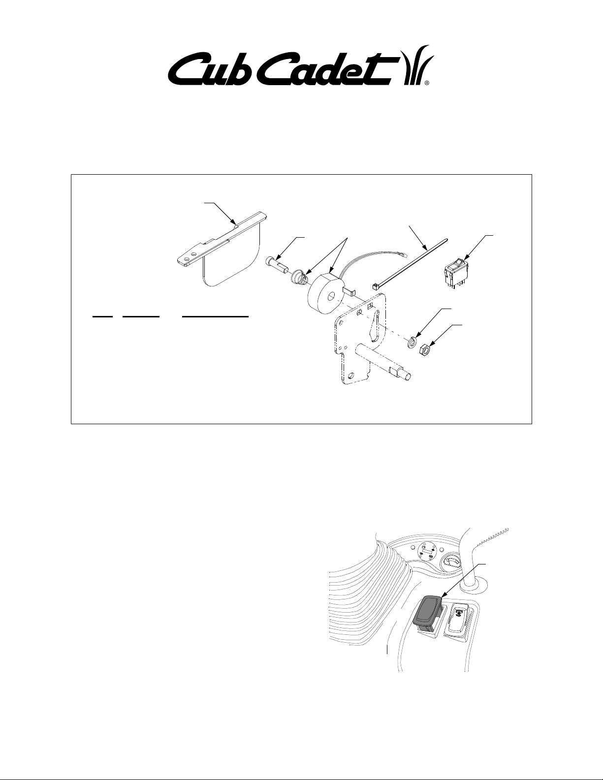
759-04080 CRUISE CONTROL KIT
For Series 6000 Tractor Models
KIT COMPONENTS
3
5
1
2
6
Ref. Pt. No. Description
1.
1750736
2.
1768971
3.
703-05791
4.
712-0240
5.
725-0157
6.
725-04246
7. 736-0171 Lock Washer, 7/16"
Introduction
The cruise control kit is designed to allow the tractor operator to maintain a desired “foot free” forward speed
in areas where constant speed changes are not required. The cruise control feature can only be operated
in the forward direction.
Installing the Cruise Control Kit
NOTE: Some installation procedures are more easily
performed from beneath the tractor. If equipped, the
mower deck may be removed from the tractor to improve access.
Wire leads w/connectors needed to power the cruise
control magnet are provided in the tractor wire harness.
To install the cruise control kit, proceed as follows:
• Remove the plug from the right side of the dash
panel by sliding a thin flat edged tool beneath the
plug and prying upward. See Figure 1.
Special Screw
Magnet w/Spring Assy.
Cruise Latch Bracket
Hex Jam Nut, 7/16-20
Cable Tie
Cruise Switch
7
4
NOTE: The wire harness connector for the cruise switch
may be connected to the dash panel plug. If so, carefully
pull the wire harness connector up through the dash
panel while removing the plug. If the wire harness leads
are not connected to the plug, it will be necessary to remove the dash panel insert.
Remove
Plug
Figure 1
CUB CADET LLC P.O. BOX 361131 CLEVELAND, OHIO 44136-0019
PRINTED IN U.S.A. FORM NO. 769-01718 (3/05)
1
Page 2

• Remove the dash panel insert by removing the two
screws and lifting the insert out (See Figure 2).
• Locate the unused dash harness connector (with
green(2), green w/white, red w/black, yellow w/
black, and violet wires) inside the dash panel. Lift
the connector up through the hole in the dash panel
from which the plug was just removed.
Screws
Remove Screws
Fender
Cover
Figure 4
Dash Panel
Insert
Figure 2
• Align the cruise switch (Ref.6) and the dash harness connector so that the locator tabs on each side
of the connector will slide up on the flat area of the
switch, then plug the switch into the connector. See
Figure 3.
Cruise Switch
Flat Area
Connector
Locator Tab
Dash Harness
Connector
Figure 3
• With the light area of the switch positioned toward
the top, push the cruise switch fully into the hole in
the dash panel.
• Reinstall the dash panel insert and secure with the
two screws.
• Remove the four hex tapp screws and two truss
head screws securing the fender cover; then remove the cover from the tractor. Refer to Figure 4.
• From beneath the right running board, locate the
hex lock nut on the end of the pedal shaft. Using a
3/4" socket and long socket extension, loosen the
lock nut so that it is unthreaded beyond the end of
the pedal shaft threads. See Figure 5.
Pedal Link
Hex Lock Nut
Pedal Shaft
Bearing Plate
Figure 5
IMPORTANT: Use care to avoid damaging the hydrau-
lic outlet tubes when completing the following step.
• Using a mallet and a 3/4" or larger bar placed
against the hex lock nut, carefully drive the pedal
shaft toward the left side of the tractor.
NOTE: The control linkage of the tractor will limit the distance the pedal shaft can be moved. Do not force the
pedal shaft; move the shaft only as far as necessary to
install the lock washer and nut on the frame side of the
pedal shaft plate. Refer to Figure 6.
• Slide the compression spring (Ref. 2), large end
first, onto the special screw. Refer to Figure 6.
• Insert the double ‘D’ end of the special screw (Ref.
1) into the double ‘D’ hole of the pedal shaft plate.
Refer to Figure 6.
2
Page 3

Hex
Jam
Nut
Lock Washer
Tractor
Frame
Special Screw
Spring
Pedal Shaft Plate
Figure 6
• Slide the lock washer (Ref.7) onto the special
screw, then thread the hex jam nut (Ref.4) onto the
screw. Refer to Figure 6.
NOTE: Because of limited space between the ped-
al shaft plate and frame, it may be easier to install
the hex jam nut from the underside of the tractor.
• Fully tighten the hex jam nut onto the special
screw. Then from beneath the right running board
carefully retighten the hex lock nut to reposition the
pedal shaft. Refer to Figure 5.
• Hook the bent tab of the magnet (Ref. 2) into the
square hole of the pedal shaft plate and pivot the
magnet onto the special screw (See Figure 7).
Push the magnet onto the screw so that the bent
tab is behind the plate and retains the magnet on
the screw.
• Insert the cruise latch bracket (Ref. 3) down
through the opening in the fender/running board so
that its large plate area is against the left side of
the magnet. See Figure 8.
Hex Tapp
Screw
Drive Shaft Shield
Magnet
Cruise
Latch
Bracket
Figure 8
• Pivot the rear of the cruise latch bracket downward
so that the bracket mounting holes align with the
holes of the drive shaft shield. Refer to Figure 8.
• While holding the cruise latch bracket tightly
against the magnet, secure the bracket with the
two hex tapp screws removed earlier. Refer to Figure 8.
• Locate the unused two wire connector of the main
wire harness along the right side of the frame (See
Figure 9). Plug the two wires from the magnet into
the wire harness connector.
Magnet
Bent Tab
Hook tab &
pivot onto
Square
Hole
screw
Figure 7
• Remove the two hex tapp screws securing the
right side of the tractor drive shaft shield to the
frame. Refer to Figure 8.
Drive Shaft
Main Harness
Wire Harness
Connector
Figure 9
• Use the cable tie (Ref.5) to secure the wire harness lead and magnet wires to the main harness,
away from the drive shaft. Refer to Figure 9.
3
Page 4

Setting The Cruise Control
WARNING: Always use extreme caution
when operating the tractor with the
cruise control engaged. Use good judgement and maintain a safe speed for the
conditions of operation.
NOTE: The cruise control feature can only be operat-
ed in the forward direction.
• Slowly depress the forward control pedal until the
desired speed is achieved.
• While holding the forward control pedal, depress
the top of cruise control switch to energize the
magnet and engage the cruise control. NOTE: The
light of the switch will illuminate to indicate the
switch has been depressed to the "ON" position.
• If the cruise control has engaged, the forward control pedal will lock in the desired position, and the
tractor will maintain the same forward speed when
you remove your foot from the pedal.
• If you wish to increase the speed while the cruise
control is engaged, simply depress the forward
pedal further. It is not necessary to disengage and
re-engage the cruise control.
Disengaging the Cruise Control
NOTE: Regardless of the method used, the indicator
light in the cruise switch will turn off when the cruise
control is disengaged. Simply depress the top of the
switch to re-engage the cruise control.
Disengage the cruise control using one of the following
methods:
• Depress the brake pedal to disengage the cruise
control and stop the tractor.
• Depress the bottom of the cruise control switch to
disengage the cruise control.
NOTE: Although not recommended, depressing the
forward/reverse pedal to the reverse position will also
disengage the cruise control.
To change to the reverse direction when operating with
cruise control, use one of the recommended methods
to disengage the cruise control, then depress the reverse control pedal.
4
 Loading...