

Page 1
Operator’s Manual
Models
724 STE
926 STE
Model 926 STE shown
IMPORTANT: Read safety rules and instructions carefully before operating equipment.
Warning:
covered, brush-covered or grass-covered land unless the engine’s exhaust system is equipped with a spark arrester meeting
applicable local or state laws (if any). If a spark arrester is used, it should be maintained in effective working order by the operator.
In the State of California the above is required by law (Section 4442 of the California Public Resources Code). Other states may have
similar laws. Federal laws apply on federal lands. A spark arrester for the muffler is available through your nearest engine authorized
service dealer or contact the service department, P.O. Box 368023 Cleveland, Ohio 44136-9722.
PRINTED IN U.S.A.
This unit is equipped with an internal combustion engine and should not be used on or near any unimproved forest-
CUB CADET CORP. P.O. BOX 368023 CLEVELAND, OHIO 44136-9722
FORM NO.
770-10008B
(6/2000)
Page 2

TABLE OF CONTENTS
Content Page
Important Safe Operation Practices...................................................................3
Loose Parts .......................................................................................................5
Assembling Your Snow Thrower .......................................................................5
Know Your Snow Thrower.................................................................................7
Operating Your Snow Thrower ..........................................................................9
Making Adjustments ..........................................................................................11
Maintaining Your Snow Thrower........................................................................12
Servicing Your Snow Thrower ...........................................................................13
Troubleshooting.................................................................................................16
Parts List............................................................................................................17
FINDING MODEL NUMBER
This Operator’s Manual is an important part of your new Snow Thrower. It will help you assemble, prepare
and maintain the unit for best performance. Please read and understand what it says.
Before you start assembling your new equipment, please locate the model plate on the
equipment and copy the information from it in the space provided below. The information on
the model plat e is very import ant if you ne ed help fr om your loca l authorize d Cub Cade t
dealer.
You can locate the model number by looking at the lower frame cover on the rear of your snow thrower. A
sample model plate is explained below. For future reference, please copy the model number and the serial
number of the equipment in the space below.
Copy the model number here:
CUB CADET CORP.
P.O. BOX 368023
CLEVELAND, OHIO 44136
Copy the serial number here:
CALLING CUSTOMER SUPPORT
If you have difficulty assembling this product or have any questions regarding the controls, operation or
maintenance of this unit, please call the Customer Dealer Referral Line.
Call 1- (800)-528-1009 to reach the Customer Dealer Referral Line. Please have your unit’s
model number and serial number ready when you call. See previous section to locate this
information.
2
Page 3

SECTION 1: IMPORTANT SAFE OPERATION PRACTICES
This symbol points out important safety instructions which, if not followed, could endanger the personal
safety and/or property of yourself and others. Read and follow all instructions in this manual before
attempting to operate this machine. Failure to comply with these instructions may result in personal
injury. When you see this symbol—heed its warning.
WARNING: Engine Exhaust, some of its constituents, and certain vehicle components contain or emit
chemicals known to State of California to cause cancer and birth defects or other reproductive harm.
DANGER: This machine was built to be operated according to the rules for safe operation in this
manual. As with any type of power equipment, carelessness or error on the part of the operator can
result in serious injury. This machine is capable of amputating hands and feet and throwing objects.
Failure to observe the following safety instructions could result in serious injury or death.
Training
1. Read, understand, a nd follow all in struction s on the
machine and in the manual(s ) before a ttempting to
assemble and o perate. Keep this ma nual in a safe pl ace
for future and regular re ference a nd for orde ring
replacement parts.
2. Be familiar with all controls and their prope r operation.
Know how to stop the mach ine and d isengage them
quickly.
3. Never allow childre n under 14 y ears old to operate this
machine. Children 14 years old and over should rea d and
understand the op eration in struction s and sa fety rules i n
this manual and should be trained and sup ervised b y a
parent.
4. Never allow adults to operate this machine without
proper instruction.
5. Thrown objects can cause seriou s personal injury . Plan
your snow throwin g pattern to avoid di scharge of mat erial
toward roads, bystanders and the like.
6. Keep bystanders, hel pers, pets and chi ldren at l east 75
feet from the machin e while it is in operatio n. Stop
machine if anyo ne enters the area.
7. Exercise caution to avoid s lipping o r falli ng, espe cially
when operating in reverse.
Preparation
1. Thoroughly inspect the area wh ere the eq uipment i s to
be used. Remove all door mat s, newspa pers, sle ds,
boards, wires and o ther foreig n object s which c ould be
tripped over or throw n by the auger/imp eller.
2. Always wear safet y glasses or eye s hields d uring
operation and while performing an adjustment or repair to
protect your eyes. T hrown ob jects whi ch ricochet can
cause serious inj ury to the eyes.
3. Do not operate wit hout wearing adequate winter outer
garments. Do not wear jewelry, long scarves or other
loose clothing which cou ld becom e entang led in m oving
parts. Wear footwear w hich wi ll improve footing on
slippery surfaces.
4. Use a grounded three wire ex tension cord and receptac le
for all units with electric start engi nes.
5. Adjust collector housing height to clear gravel or crushed
rock surfaces.
6. Disengage all cl utch levers before st arting the engin e.
7. Never attempt to m ake any adjustme nts while engine i s
running, except where spec ifically recomm ended in the
operator’s manual.
8. Let engine and m achine adju st to outd oor tem perature
before starting to clear snow.
9. To avoid personal injury or pro perty damage use extre me
care in handling gasolin e. Gasol ine is e xtremely
flammable and the v apors are explosiv e. Serious
personal injury c an occur w hen gas oline is spilled o n
yourself or your c lothes which c an ignit e. Wash y our skin
and change clot hes immedi ately.
a. Use only an approved gasoline container.
b. Extinguish all cigarettes, cig ars, pipes and other
sources of ignition.
c. Never fuel machine indoo rs.
d. Never remove gas cap or add fue l whil e the
engine is hot or running.
e. Allow engine to cool at leas t two minu tes before
refueling.
f. Never over fill fuel tank. Fil l tank to no more tha n
½ inch below bottom of fill er neck to provide space
for fuel expansi on.
g. Replace gasoli ne cap an d tighten secu rely.
h. If gasoline is sp illed, wip e it off th e engine and
equipment. Move machine to another area . Wait 5
minutes before start ing the e ngine.
i. Never store the machine or fuel containe r inside
where there is an o pen flam e, spark or pilot l ight
(e.g. furnace, water heater, space heate r, clothes
dryer etc.).
j. Allow machine to cool 5 minute s before storin g.
Operation
1. Do not put hands o r feet near rotating p arts, in the a uger/
impeller housing o r disc harge chu te. Cont act wit h the
rotating parts can am putate ha nds and feet.
2. The auger/impelle r clutch lev er is a safety de vice. Nev er
bypass its operati on. Doing so, makes the ma chine
unsafe and may cause p ersonal i njury.
3. The clutch leve rs must o perate easily in both d irections
and automatical ly return to the disengaged pos ition when
released.
4. Never operate with a miss ing or da maged di scharge
chute. Keep all safe ty devic es in pl ace and working.
3
Page 4
5. Never run an engine indoors or in a poorly vent ilated
area. Engine exhaust contains carbon monoxide , an
odorless and dea dly gas .
6. Do not operate mac hine while under the influenc e of
alcohol or drugs.
7. Muffler and engine be come hot and c an cause a burn. D o
not touch.
8. Exercise extreme ca ution when operating on or cro ssing
gravel surfaces. Stay alert for hidden hazards or traffic.
9. Exercise caution w hen changi ng directi on and w hile
operating on slop es.
10. Plan your snow t hrowing pat tern to av oid disc harge
towards windows, wa lls, cars e tc. To avoid prope rty
damage or personal injury caus ed by a ricochet.
11. Never direct disc harge at c hildren, b ystander s and pet s
or allow anyone in front of t he machi ne.
12. Do not overload machine capa city by attemptin g to clear
snow at too fast of a rate.
13. Never operate this machin e without good visib ility or light.
Always be sure of your footi ng and k eep a firm hold on
the handles. Walk, n ever run.
14. Disengage power to t he aug er/impeller w hen
transporting or not in use.
15. Never operate mach ine at hi gh transp ort speeds on
slippery surfaces. Look down and b ehind an d use ca re
when in reverse.
16. If the machine shoul d start to vibrate abn ormally, stop the
engine, disconnect the spark plug an d grou nd it agai nst
the engine. Inspect thoroughly for dam age. Repair any
damage before starting and ope rating.
17. Disengage all cl utch lev ers and st op engin e before y ou
leave the operating position (be hind the handles). Wai t
until the auger/im peller come s to a complete stop befo re
unclogging the d ischarge chute, m aking an y
adjustments, or inspecti ons.
18. Never put your hand in the d ischarge or colle ctor
openings. Always use a cl earing to ol to unc log the
discharge opening.
19. Use only attach ments a nd acce ssories approved by the
manufacturer (e.g. wheel weigh ts, tire c hains, cabs etc.) .
20. If situations occur which are not covered in this manua l,
use care and good judgment. Cont act your dealer or
telephone 1-800-528-10 09 for assistance and the name
of your nearest s ervicing dealer.
Maintenance And Storage
1. Never tamper with safety devices. Check their proper
operation regularly.
2. Disengage all cl utch lev ers and stop engi ne. Wait u ntil
the auger/impelle r come to a complet e stop. D isconn ect
the spark plug wi re and grou nd again st the en gine to
prevent unintended starting before cl eaning, repairi ng, or
inspecting.
3. Check bolts, and sc rews for pro per tig htness at frequent
intervals to keep t he ma chine in safe worki ng condi tion.
Also, visually inspe ct mach ine for an y damag e.
4. Do not change the engi ne governor settin g or over-speed
the engine. The g overnor c ontrols the m aximum s afe
operating speed o f the eng ine.
5. Snow thrower shave plates an d skid shoes are subj ect to
wear and damage. F or your s afety protecti on, freque ntly
check all compon ents and replace with origin al
equipment manuf acturer’s (O.E.M.) parts only. Use of
parts which do not m eet the ori ginal eq uipment
specifications may lea d to imp roper perfor mance an d
compromise safety.
6. Check clutch co ntrols period ically to verify they engage
and disengage prope rly and adjust, if ne cessary. Refer to
the adjustment s ection i n this op erator’s man ual for
instructions.
7. Maintain or replace safety and instruction labels, as
necessary.
8. Observe proper disposal l aws and regulations for ga s, oil,
etc. to protect the environmen t.
9. Prior to storing, run machine a few minutes to clear snow
from machine an d prevent freeze up of auger/i mpeller.
10. Never store the machine or fuel c ontainer i nside whe re
there is an open flame, spark or pilot light such as a wate r
heater, furnace ,cloth es dryer etc .
11. Always refer to the operator’s ma nual for p roper
instructions on off-season storage.
Your Responsibility:
Restrict the use of this p ower ma chine to persons wh o read,
understand and fo llow the w arnings and ins tructions in this
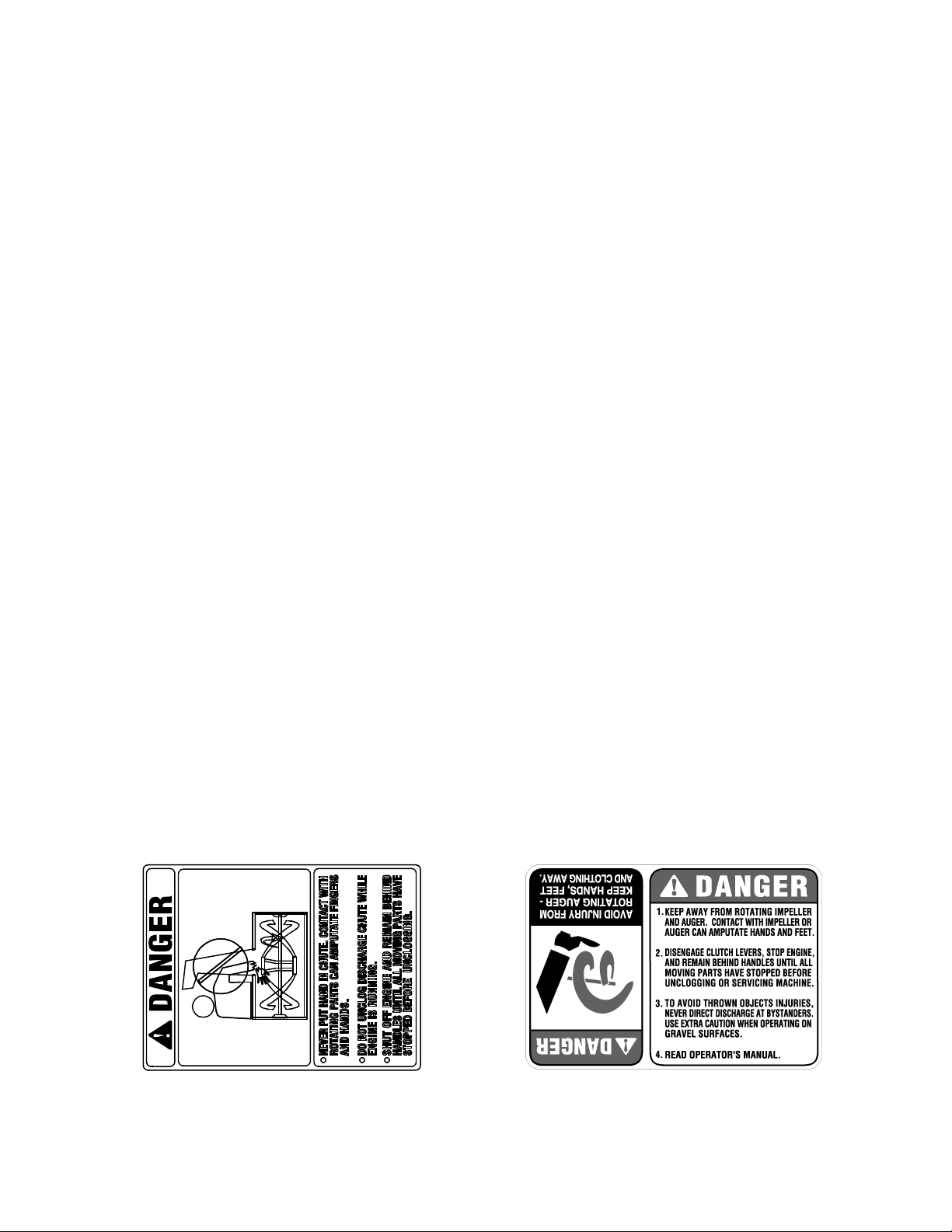
manual and on t he mach ine. The s afety la bels ar e given
below for your refer ence.
4
Page 5
SECTION 2: LOOSE PARTS
The snow thrower is shipped with the following loose parts in the carton. Please remove all loose parts from the
carton before discarding it. See below to identify the parts, noting that these parts may be referred to again in the
following sections of the manual. Part numbers are shown in parentheses.
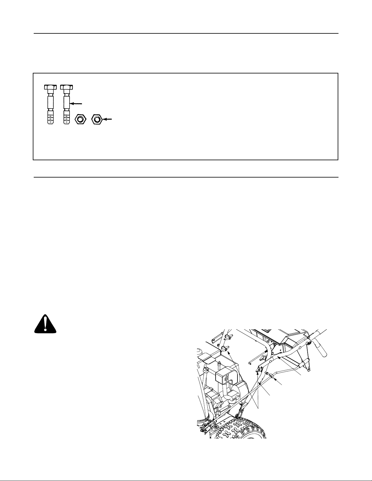
Auger Shear Bolts
Shear Bolts
(710-0890A)
Hex Lock Nuts
(712-0429)
The augers are secured to the auger shaft with two shear bolts and
hex lock nuts. If you hit a foreign object or ice jam, the snow thrower
is designed so that the bolts may shear. Two replacement shear
bolts and nuts ar e provid ed for your conveni ence. Sto re in a safe
place until needed.
IMPORT ANT :
hex bolts. Any damage to the auger gearbox or other components
as a result of doing so will NOT be covered by your snow thrower’s
warranty.
NEVER replace the auger shear bolts with standard
Figure 1
SECTION 3: ASSEMBLING YOUR SNOW THROWER
NOTE: Any reference in this manual to the left or right
side of the snow thrower is observed from the
operator’s position.
IMPORT ANT :
later on in this section BEFORE operating your snow
thrower. Failure to follow the instructions may cause
damage to the snow thrower.
• Remove the screws from the top, sides, and ends
of the shipping carton.
• Set the panels aside to avoid tire punctures or
personal injury.
• Remove and discard the plastic bag that covers the
unit.
• Roll the unit out of the carton.
Make any final adjustments as instructed
WARNING: Disconnect the spark plug
and ground it against the engine to pr event
unintended starting.
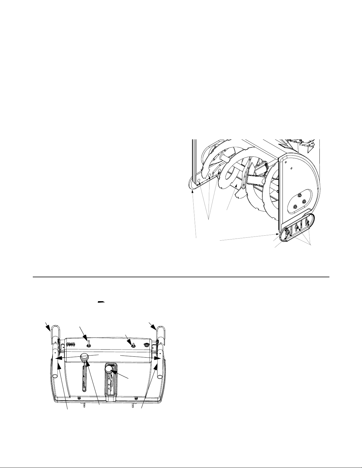
• Model 926 STE: Remove the low er two plastic
wing nuts, cupped washers and carriage bolts from
each side of the lower handle. See Figure 2.
• Model 724 STE: Remove the lower two plastic
wing nuts, cupped washers and carriage bolt
(eyebolt on the left side) from the lower handle.
See Figure 2.
• Raise the upper handle assembly until it locks over
the lower handle. See Figure 3.
• Look at the lower rear of the snow thrower frame to
be sure all the cables are aligned with the cable
roller guides.
• Model 926 STE: Secure the upper handle and
lower handle with the two plastic wing nuts, cupped
washers and carriage bolts previously removed and
tighten the upper two plastic wing nuts.
• Model 724 STE: Secure the upper handle and
lower handle with the two plastic wing knobs,
cupped washers and carriage bolt (eyebolt on left
side) previously removed. See Figure 3.
• Model 724 STE: Adjust the eyebolt on the chute
directional control so the rod does not come into
contact with the engine by moving the hex nut
against the handle (if necessary). Retighten the
wing nut to secure the directional control in this
position.
• Slide the shift rod connector down over the end of
the lower shift rod. See Figure 3. Tap the connector
until it locks over the lower shift rod.
Upper Handle
Eyebolt
Lower Handle
Wing Knobs, Washers,
& Bolts
Model 724 STE shown
Figure 2
5
Page 6
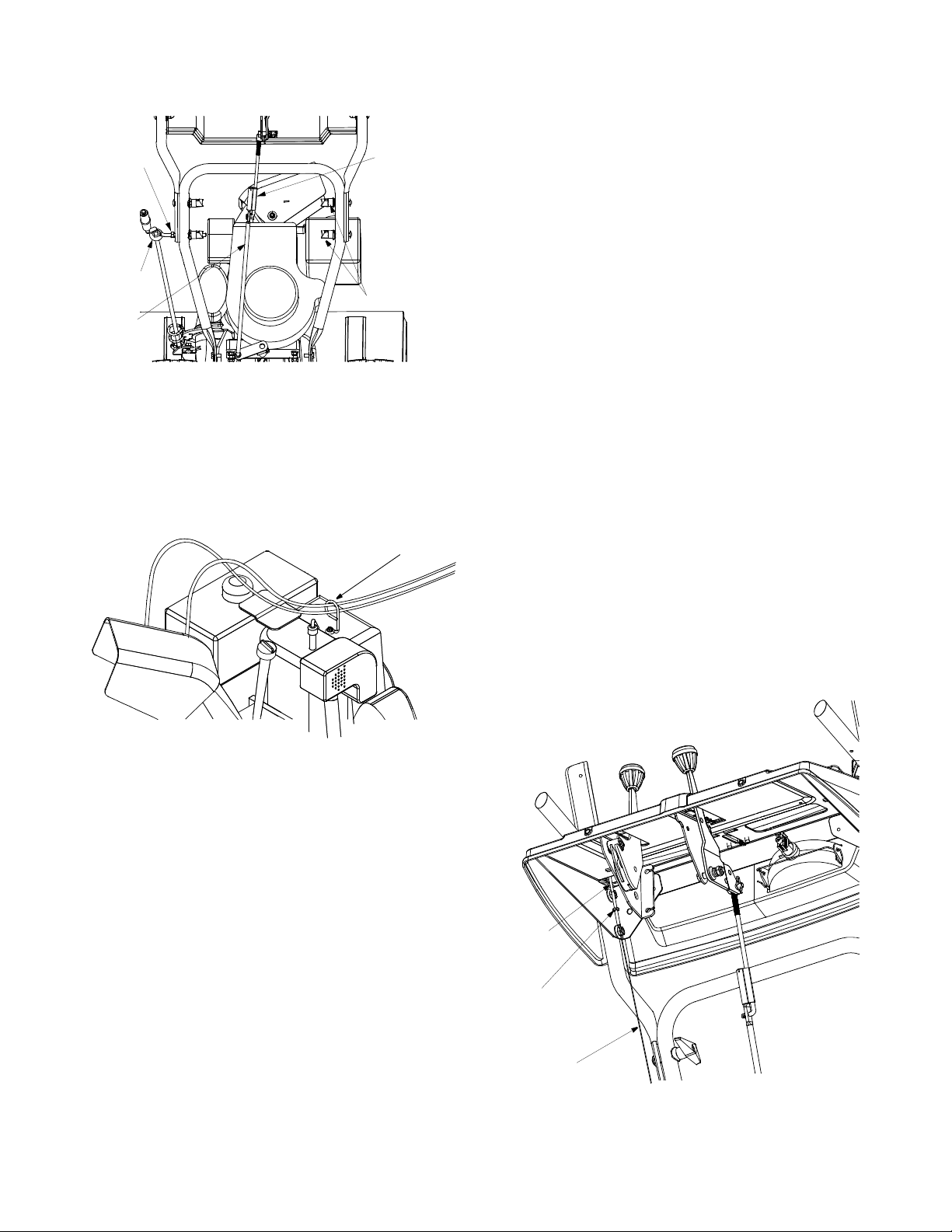
Hex Nut
Eyebolt
Lower
Shift Rod
Figure 3
Shift Rod
Connector
Wing Knobs
NOTE: If the connector is not properly assembled, the
shift rod will pivot and y ou will not be able to change
speeds or change directions.
• If not already attached, slip the cables that run from
the handle panel to the chute into the cable guide
located on top of the engine. See Figure 4.
Cable Guide
• Loosen the jam nut and thread the cable in (for less
slack) or out (for more slack) as necessary. See
Figure 5 .
• Recheck th e adjustm ent bef ore reti ghtenin g the
jam nut against the cable.
Traction Control and Shift Lever Adjustment
NOTE: It is eas ier to maneuver a non-running sno w
thrower with both track steering controls held in
simultaneously.
To check the adjustment of the traction control and shift
lever, proceed as follows:
• Move the shift lever into the sixth (6) position.
a. With the traction control (see Figure 7 )
released, push the snow thrower forward,
then pull it back. Disregarding the overall
weight of the snow thrower, the machine
should otherwise move freely.
b. Engage the traction control, and attempt to
move the machine both forward and
rearward. You should experience resistance
as the wheels should not be turning.
• Move the shift lever into the fast reverse (R2)
position and repeat the previous steps (a & b).
If you experienced resistance either when repositioning
the shift lever (see Figure 7 ) from position 6 to R2 or
when attempting to move the machine forward or
rearward with the traction control released, your snow
thrower’s traction control is in need of adjustment and
you should NOT operate the snow thrower before
completing the adjustment as follows:
Figure 4
• Unwrap the headlight wire, which is attached to the
headlight beneath the handle panel.
• Wind the headlight wire around the right handle
until excess slack i s remo ved.
• Plug the wire from the right side of the engine,
beneath the fuel tank.
Final Adjustments
Auger Control Adjustment
Check the adjustment of the auger control as follows:
• Push forward on the auger control (Refer to Figure
7 ) until the small rubber bumper contacts the upper
handle. There should be slack in the cable. See
Figure 5 .
• Release the auger control. The cable should be
straight. Make certain you can depress the auger
control against the left handle completely without
using excess force.
If adjustment is necessary, proceed as follows:
“Z” End
Jam Nut
Auger Control Cable
Figure 5
6
Page 7
• Loosen the jam nut on the traction control cable
(located opposite the auger control cable) and
UNTHREAD the cable one full turn.
• Recheck t he ad justm ent.
• Retighten the jam nut to secure the cable when the
correct adjustment is reached.
If the machine can be moved freely both forward and
rearward with the traction control fully depressed,
proceed as follows:
• Loosen the jam nut on the traction drive cable and
THREAD the cable in one full turn.
• Recheck the adjustment and repeat the adjustment
as necessary.
• Retighten the jam nut to secure the cable when the
correct adjustment is reached.
NOTE: If you are uncertain that you have reached the
correct adjustment, refer to the Traction Control
Adjustment in the previous column.
Skid Shoe Adjustment
The space between the shave plate and the ground can
be adjusted by repositioning the skid shoes found on
either side of the snow throwers auger housing. For
smooth surface snow removal such as on an asphalt
driveway, place the skid shoes in a lower position. Use
a higher position when the area to be cleared is
uneven. See Figure 6.
• Loosen, but do NOT remove, the three hex nuts
which fasten the skid shoe to the auger housing.
• Move the skid shoe to the desired position.
NOTE: Ma ke certain th e entire bottom surface of the
skidshoe is against the ground to avoid uneven wear on
the skid shoes.
• Retighten the hex nuts loosened earlier.
• Repeat this adjustment on the skid shoe found on
the opposite side of the snow thrower.
NOTE: The skid shoes are reversible on this machine.
When one side wea rs out, it can be rotated 180° and
the other flat skid surface can be used.
Shave Plate
Carriage Bolts
IMPORT ANT :
gravel driveway, ALWAYS adjust the skid shoes into
When operating your snow thrower on a
Skid Shoes
the HIGHEST position.
Adjust skid shoes as follows:
SECTION 4: KNOW YOUR SNOW THROWER
Shift Lever
The shift lever is located in the center of the handle
Auger
Control
Steering Control
Chute-Rotation
Left Track
Electric
Switch
Heated Handles
Handles
Chute
Tilt
Control
Model 926 STE shown
Figure 7
Traction Control /
Auger Control Lock
Switch
Shift
Lever
Right Track
Steering Control
panel and is used to determine both ground speed and
direction of travel. It can be moved into any of eight
positions.
Forward
Your snow thrower has six forward (F) speeds. Position
one (1) is the slowest and position six (6) is the fastest.
Reverse
Your snow thrower has two reverse (R) speeds. R1 and
R2, R2 is the faster speed.
IMPORT ANT :
changing speeds.
Auger Control
The auger control is located on the left handle. See
Figure 7. Squeeze the auger control lever to engage
the augers. Release to stop the snow throwing action
(the traction control must also be released).
High
Low
Hex Nuts
Figure 6
Always release the traction control before
7
Page 8
Traction Control / Auger Cont rol Lock
The traction control is located on the right handle. See
Figure 7. Squeeze the traction control to engage the
wheel drive. Release to stop.
This same lever also locks the auger control so you
can operate the electric chute rotation switch without
interrupting the snow throwing process. If the auger
control is engaged simultaneously with the traction
control, the operator can release the auger contr ol (on
the left handle) and the augers will remain engaged.
Release the traction control to stop the augers and
wheel drive (the auger control must also be released).
Chute Directional Control (Model 724 STE)
The chute directional control is located on left side of
the snow thrower.
To change the direction in which snow is thrown, turn
chute directional control as follows:
• Crank clockwise to discharge to the left.
• Crank counterclockwise to discharge to the right.
Electric Chute-Rotation Switch (Model 926 STE)
The electric chute-rotation switch is located o n the left
side of the snow thrower handle panel.
To change the direction in which discharge d snow is
thrown, proceed as follows:
• Push the toggle switch to the left to rotate the chute
counterclockwise.
• Push the toggle switch to the right to rotate the
chute clockwis e.
IMPORT ANT :
completed its rotation cycle in either direction. Failure to
do so can result in damage to the electric chute motor
and/or its drive gear.
Release the switch once the chute has
Track Steering Control
The left and right track steering controls are located on
the underside of the handles and are used to assist in
steering the snow thrower. See Figure 7. Squeeze the
right track control when turning right, squeeze the left
control when turning left. Operate your snow thrower in
open areas until you become familiar with these
controls.
NOTE: The heated grips are a compliment, NOT a
substitute for proper cold weather outerwear for hands.
It is recommended that the user wear gloves/mittens
when operating this snow thrower.
IMPORT ANT :
left into the OFF position after using the snow thrower.
Chute Tilt Control
The distance snow is thrown can be changed by
adjusting the angle of the chute assembly. Move the
chute tilt control forward to decrease the distance,
toward the rear to increase. See Figure 7.
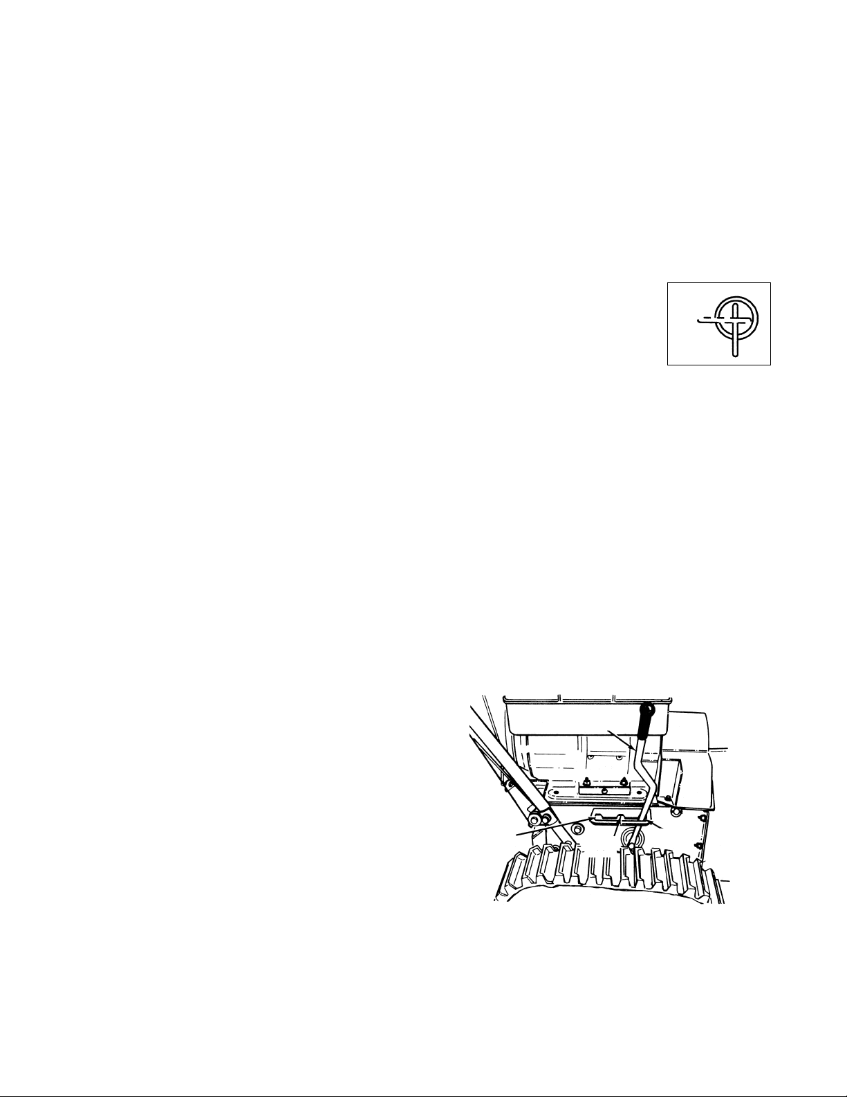
Fuel Shut-Off Valve
The fuel shut-off valve, located under
the fuel tank, controls fuel flow from
the tank. Always make certain it is in
the Open ( vert ical ) posi tion befo re
attempting to start the engine.
Track Lock Lever
The track lock lever is located on the right side of the
snow thrower and is used to select the position of the
auger housing and the method of track operation. See
Figure 8. Move the lever to the right, then forward or
backward to one of the three positions.
Transport—Raises the front end of the snow thrower for
easy transport. Using proper caution, this position may
also be used on many gravel driveways to clear snow
while leaving gravel undisturbed.
Normal Snow—Allows the tracks to be suspended
independently for continuous ground contact.
Packed Snow—Locks the front end of the snow thrower
down to the ground for hard-packed or icy snow
conditions.
Toggle the heated handles switch to the
Closed
Open
Track
Lock Lever
NOTE: It is eas ier to maneuver a non-running sno w
thrower with both track steering controls held in
simultaneously.
Heated Handles Switch (Model 926 STE)
The heated handles switch is located on the right side
of the snow thrower handle panel. See Figure 7. To
activate the heated handles, toggle the switch to the
right to generate heat within the handle grips.
Packed
Snow
8
Normal
Snow
Figure 8
Transport
Page 9
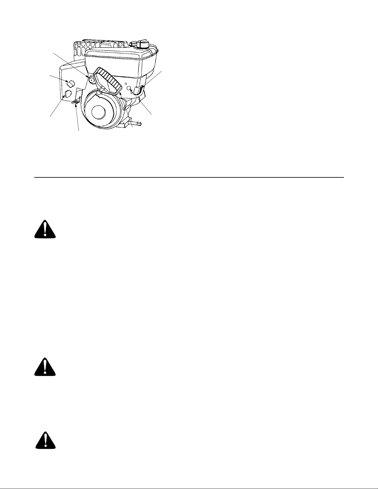
Headlight
Primer
Choke
Switch
Box
The headlight is on whenever the engine is running.
Throttle Control
The throttle control is located on the engine. It regulates
the speed of the engine and will shut off the engine
when pushed down completely. See Figure 9.
Safety Ignition Key
The safety ignition key must be fully inserted in the
switch before the unit will start. Remove the ignition key
when the snow thrower is not in use. See Figure 9.
IMPORT ANT :
Do NOT attempt to turn the key.
Ignition
Key
Throttle
Control
Figure 9
Recoil
Starter
Handle
Electric
Starter
Button
SECTION 5: OPERATING YOUR SNOW THROWER
Before Starting
WARNING: Read, unde rstand, and follow
all instructions and warnin gs on th e machine
and in this manual before operating.
• The spark plug wire was disconnected for safety
purposes during assembly. Attach spark plug wire
to spark plug before starting.
Gas And Oil Fill-Up
IMPORT ANT :
shipped with oil already in the engine, you MUST check
the engine oil level as instructed in the separate engine
manual packed with your unit BEFORE starting the
engine for the first time. Read instructions carefully.
Service the engine with gasoline and oil as
instructed in the separate engine manual packed with
your snow thrower. Read instructions carefully.
Although your snow thrower comes
WARNING: Use extreme care when
handling gasoline. Gasoline is extremely
flammable and the vapors are explosive.
Never fuel machine indoors or while the
engine is hot or running. Extinguish
cigarettes, cigars, pipes and other sources of
ignition.
Electric Starter
WARNING: The electric starter is
equipped with a three-wir e power cord and
plug, and is desig ned to operat e on 12 0 volt
AC household current. It must be prop erly grounded at
all times to avoid the possi bility of electric sh ock which
may cause injury to the operator. Follow all instructions
carefully. Determine that your house wiring is a threewire grounded system. A sk a lic en se d ele ct ri cian if you
are not certain. If your house wiring system is not a
three-wire grounded system, do not use this electric
starter under any conditions. If your system is grounded
and a three-hole receptacle is not available at the point
your starter will normally be used, one should be
installed by a licensed electrician.
When connecting the power cord, always connect the
cord to the starter on the engine first, then plug the
other end into a three-hole grounded receptacle.
When disconnecting the power cord, always unplug the
end from the three-hole grounded receptacle first.
To Start Engine
IMPORT ANT :
(traction dr ive or aug ers) with the control s diseng aged,
shut the engine off immediately. Readjust as instructed
under Final Adjustments in Section 3 of this manual.
• Attach the spark plug wire to the spark plug.
• Make certain the fuel shut-off valve is in the open
(vertical) position.
• Make certain that both the auger control and the
traction control are in the disengaged position.
• Move the throttle control up to the FAST position.
Insert the ignition key into the slot. See Figure 9. Be
certain it snaps into place. Do not turn the key.
• Rotate the choke knob to the FULL choke position
(cold engine start). If the engine is warm, place the
choke in the OFF position.
If the unit shows any sign of motion
9
Page 10

• Connect the power cord (electric start) to the switch
box on the engine. Plug the other end of power cord
into a three-hole, grounded 120 volt AC receptacle.
• Push the primer button three times. If the engine is
warm, push the primer button once only. See
Figure 9.
NOTE: Always cover the vent hole in the primer
button when pushing. Additional priming may be
necessary for cold starts if the temperature is below
°
15
F.
• Electric Start: Push the starter button on the front
of the engine to turn the starter. When the engine
starts, release the starter button (see Figure 9).
• Recoil Start: Grasp the starter handle (see Figure
9) and pull the rope out slowly until resistance is
felt. Pull the starter handle rapidly. Do not allow the
handle to snap back. Allow it to rewind slowly while
keeping a firm hold on the starter handle.
• As the engine warms up and begins to operate
evenly, rotate the choke knob slowly to the OFF
position. If the engine falters, return to FULL choke,
then slowly move to the OFF position.
To Stop Engine
• Run the engine for a few minutes after throwing
snow, to help dry off any moisture on the engine.
• To help prevent possible freeze-up of the starter,
proceed as follows:
Electric Starter: Connect the power cord to the
switch box on the engine, then connect to a 120
volt AC receptacle. With the engine running, push
the starter button and spin the starter for several
seconds. The unusual sound made by the spinning
starter will not harm the engine or starter.
Disconnect the power cord from receptacle first,
and then from the switch box.
Recoil Starter: With the engine running, pull the
starter rope with a rapid, continuous full arm stroke
three or four times. Pulling the starter rope will produce a clattering sound, which is not harmful to the
engine or the recoil starter.
• To stop the engine, push the throttle control lever
down to the stop position. Remove the ignition key
by pulling it straight out of the keyhole and
disconnect the spark plug wire from the spark plug
to prevent accidental starting while the equipment
is unattended.
NOTE: Do not los e the i gnition ke y. Keep it in a safe
place. The engine will not start without the ignition key.
To Engage Track Drive
• With the engine running near top speed, move the
shift lever into one of the six FORWARD positions
or two REVERSE positions. Select a speed
appropriate for the snow conditions that exist.
NOTE: Use slower speeds in hi gher snow and until
you are familiar with the operation of the snow thrower.
• Squeeze the traction control against the right
handle and the snow thrower will move. Release it
and the drive motion will stop.
IMPORT ANT :
releasing the traction control. Doing so will cause
premature wear to the drive system’s friction wheel.
NEVER move the shift lever without first
To Engage Augers
To engage the augers and start the snow throwing
action, proceed as follows:
• Squeeze the auger control against the left handle.
To disengage power to the augers:
• Release both the auger control and the traction
control, if engaged.
The auger control can be locked so you can turn the
electric chute directional control without interrupting the
snow throwing process. Refer to Traction Control/
Auger Control Lock in Section 4 of this manual.
Operating Tips
NOTE: Allow the engine to warm up for a few minutes.
The engine will not develop full power until it reach es
operating temperature.
WARNING: Muffler and surrounding areas
of the engine become hot and can cause a
burn. Do not touch.
• For the most efficient snow removal, remove snow
immediately after it falls.
• Discharge the snow downwind whenever possible.
• Slightly overlap each previous path.
• Set the skid shoes 1/4" below the shave plate for
normal usage. The skid shoes may be adjusted
upward (to lo wer the sh ave plat e) for har d-packe d
snow. Adjust downward (to raise the shave plate)
when using on gravel or crushed rock.
• Be certain to follow the precautions found in the To
Stop Engi ne sec tion to pr even t possi ble freez e-up.
• Clean the snow thrower thoroughly after each use.
• Wipe all snow and moisture from the carburetor
cover in the area of the control levers. Also, move
the control levers back and forth several times.
Leave the throttle control lever in the STOP or OFF
position. Leave the choke control in the FULL
choke position. See Figure 9.
10
Page 11
SECTION 6: MAKING ADJUSTMENTS
WARNING: NEVER attempt to make adjustments
while the engine is run ning, except where specifie d in
the operator’s manual.
Chute Directional Adjustment
The distance snow is thrown can be adjusted by
adjusting the angle of the chute assembly. Refer to the
Chute Tilt Cont rol i n the Know Your Sn ow Th rower
Section.
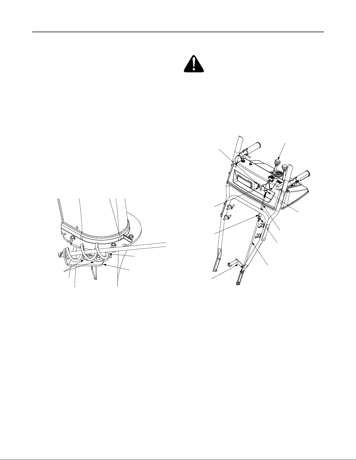
Chute Directional Contr ol And Support
Bracket Adjustment (Model 724 STE)
If the spiral at the bass of the chute directional control is
not fully engaging with the notches in the lower chute
assembly, the support bracket can be adjusted inward
or outward as follows:
• Loosen, but do NOT remove the hex nuts which
secure the chute directional control support bracket
to the snow thrower housing. See Figure 10.
WARNING: Dra in the gasoline out of your
snow thrower’s engine, or place a piece of
plastic film under the gas cap to avoid
spillage befor e ma king th is a djust ment.
• Tip the snow thrower forward, allowing it to rest on
the auger housing.
• Remove the frame cover underneath the snow
thrower by removing the six self-tapping screws.
• With the traction control released, there must be
clearance between the friction wheel and the drive
plate in all positions of the shift lever.
Hairpin
Clip
Flat
Washer
Shift Lever
Ferrule
Spiral
Hex Nuts
Figure 10
• Adjust the support bracket inward or outward so
that the spiral is fully engaged in the notches on the
chute before retightening the hex nuts.
Support
Bracket
Skid Shoe Adjustment
The space between the shave plate and the ground can
be adjusted by raising or lowering the skid shoes. Refer
to Skid Shoe Adjustment in Section 3 of this manual.
Traction Control Adjustment
Refer to the information found under the heading Final
Adjustments in Section 3 of this manual to adjust the
traction control. If you are uncertain that you have
reached the correct adjustment, proceed as follows:
Clutch Rod
Connector
Shift Arm
Figure 11
• With the traction control engaged, the friction wheel
must contact the drive plate. See Figure 12.
If adjustment is necessary:
• Loosen the jam nut on the traction drive cable (see
Figure 5). Adjust the cable as necessary.
• Retighten the jam nut to secure the cable when
correct adjustment is reached and reassemble.
Upper Shift Rod
Hairpin Clip
Lower Shift Rod
NOTE: If you placed plastic film under the gas cap, be
certain to remove it before operating the snow thrower.
11
Page 12

Drive Shaft
Drive
Sprocket
Shaft
Friction
Wheel
Rubber
Figure 12
Cable
Pivot
Rod
Drive
Plate
Auger Control Adjustment
Refer to the information found under the heading Final
Adjustments in Section 3 of this manual to adjust the
auger control.
Shift Rod Adjustment
To adjust the shift rod, proceed as follows.
• Remove the hairpin clip and slide the clutch rod
connector up, to separate the upper shift rod from
the lower shift rod. See Figure 10.
• Place the shift lever into the sixth (6) position.
• Rotate the shift arm clockwise (from the operator’s
position) as far as it will go.
• Thread the upper shift rod downward until the
elbow on its lower end aligns with the hole found in
the lower shift rod.
• Reconnect the upper shift rod to the lower shift rod
by reinserting the hairpin clip removed earlier and
sliding clutch rod connector back down into place.
IMPORT ANT :
adjustment of the shift rod as instructed under the
heading Final Adjustments in Section 3 of this manual,
before operating the snow thrower.
Make certain t o check for cor rect
SECTION 7: MAINTAINING YOUR SNOW THROWER
Lubrication
WARNING: Disconnect the spark plug wire
and ground it against the engine before
performing any maintenance procedures.
Engine
Refer to the separate engine m anual p acked with yo ur
unit for all engine lubrication instructions.
WARNING: When following instruc tions in
the separate engine manual for draining oil,
be sure to protect the frame to avoid oil
dripping onto transmission parts.
Electric Chute-Rotation Motor (Model 926 STE)
The gear on the electric chute-rotation motor and the
base of the discharge chute itself should be lubed with
multi-purpose automotive grease once a season. See
Figure 13.
Auger Shaft
At least once a season, remove the shear bolts on the
auger shaft. Spray lubricant inside the shaft. See Figure
14. Also lubricate the plastic auger bearings at least
once a season and grease the fittings on the end of the
auger shaft with a standard grease gun.
Gear Shaft
Lubricate the gear shaft with 6-n-1 grease at least once
a season or after every 25 hours of operation (available
at automotive stores, or order part number 737-0170).
Refer to Figure 12.
IMPORT ANT :
friction wheel and aluminum drive plate.
Keep all grease and oil off of the rubbe r
Drive and Shifting Mechanism
Lubricate at least once a season or after every 25 hours
of operation. Remove the frame cover, lubricate any
chains, sprockets, gears, bearings, shafts, and shifting
mechanism at least once a season. Use engine oil or a
spray lubricant. Avoid getting oil on the friction
wheel rubber and aluminum drive plate. Refer to
Figure 12.
Lube Gear
and Chute Base
12
Figure 13
Page 13

Traction Cont rol / Auger Co ntrol Lock
Grease Fittings
Vent Plug
Shear Bolts
The cams on the ends of the control rods which
interlock the traction drive and auger drive levers must
be lubricated at least once a season or every 25 hours
of operation. The cams can be accessed beneath the
handle panel. Use a multi-purpose automotive grease.
Gear Case
The gear case is lubricated with grease at the factory.
Every 25 hours or once a season, remove the vent plug
located on the top of the gear case. If necessary, use a
grease gun on the gear case grease fitting. Lubricate
using Shell Alvania grease EPR00, part number 737-
0168. Refer to Figure 14.
IMPORT ANT :
the seals could result. Be sure the vent plug is free of
Plastic Bearings
Figure 14
grease in order to relieve pressure.
SECTION 8: SERVICING YOUR SNOW THROWER
Do not overfill the gear case. Damage to
WARNING: Disconnect the spark plug wire
and ground it against the engine before
performing any repairs or maintenance.
Engine
Refer to the separate engine manual packed with your
unit for all engine maintenance procedures.
Augers/Shear Bolts
The augers are secured to the auger shaft with two
shear bolts and hex lock nuts. Refer to Figure 14. If you
hit a foreign object or ice jam, the snow thrower is
designed so that the bolts may shear.
If the augers will not turn, check to see if the bolts have
sheared. Two replacement shear bolts and hex lock
nuts have been provided with the snow thrower. For
future use, order kit number OEM-710-0890 which
contains four replacement shear bolts and
accompanyin g hex lock nuts.
IMPORT ANT :
standard hex bolts. Any damage to the auger gearbox
or other components as a result of doing so will NOT be
covered by your snow throwers warranty.
NEVER replace the auger shear bolts with
Shave Plate And Skid Shoes
The shave plate and skid shoes on the bottom of the
snow thrower are subject to wear. They should be
checked periodically and replaced when necessary.
Refer to Figure 6.
To remove the skid shoes, remove the six carriage
bolts, belleville washers and hex nuts (three on each
side) which attach them to the snow thrower.
Reassemble the new skid shoes making sure that the
bolts and washers are reinstalled correctly. Also, make
certain the skid shoes ar e adjust ed so the flat surface is
sitting level on the ground. The skid shoes can be
rotated on this machine 180° so both flat surfaces of the
skid shoe can be utilized for wear.
To remove the shave plate, remove the carriage bolts,
belleville washers and hex nuts which attach it to the
snow thrower housing. Reassemble the new shave
plate, making sure the heads of the carriage bolts are to
the inside of the housing. Tighten securely.
13
Page 14

Belt Removal And Replacement
WARNING: Disconnect the spark plug wire
and ground it against the engine before
performing any repairs or maintenance.
Auger Belts
• Remove the plast ic bel t cove r at th e fro nt of the
engine by removing the two self-tapping screws.
See Figure 15.
• Drain the gasoline from the snow thrower, or place
a piece of plastic film under the gas cap.
• Tip the snow thrower up and forward so that it rests
on its auger housing.
Engine
Self-Tapping
Screws
Belt Cover
Auger Housing
Figure 15
• Remove the six self-tapping screws from the frame
cover underneath the snow thrower.
• Roll the front and rear auger belts off the auger
drive pulley. See Figure 16.
• Unhook the idler spring from the hex bolt on the
auger housing. See Figure 17.
• Back out the stop bolt until the support bracket
rests on the auger pulley. See Figure 18.
Wheel
Drive
Pulley
Auger
Drive
Pulley
Idler
Pulley
Frame
Wheel
Drive
Belt
Idler
Pulley
Auger
Drive
Belts
Figure 16
NOTE: If you placed plastic film under the gas cap, be
certain to remove it before operating the snow thrower.
Drive Belt
• Follow the first four steps of the instructions for
servicing the auger belts.
• Pull the idler pulley up, and lift the belt off the wheel
drive pulley and friction wheel disc. See Figure 17.
• Back out the stop bolt until the support bracket
rests on the auger pulley. See Figure 18.
• Slip the belt between the friction wheel and drive
disc. See Figure 18. Remove and replace the belt.
Reassemble following the instructions in reverse
order.
NOTE: The support bracket must rest on the stop bolt
after the new belt has been assembled. See Figure 18.
NOTE: It may be necessary to loosen the six nuts that
connect the frame to the auger housing to aid in bel t
removal.
• Lift the rear auger belt from the auger pulley, and
slip the belt between the support bracket and the
auger pulley. See Figure 17. Repeat this step for
the front auger belt.
• Replace both auger drive belts by following
instructions in reverse order.
14
Rear
Auger
Belt
Front
Auger
Belt
Support
Bracket
Auger
Pulley
Idler
Spring
Figure 17
Auger
Housing
Frame
Support
Bracket
Spring
Page 15
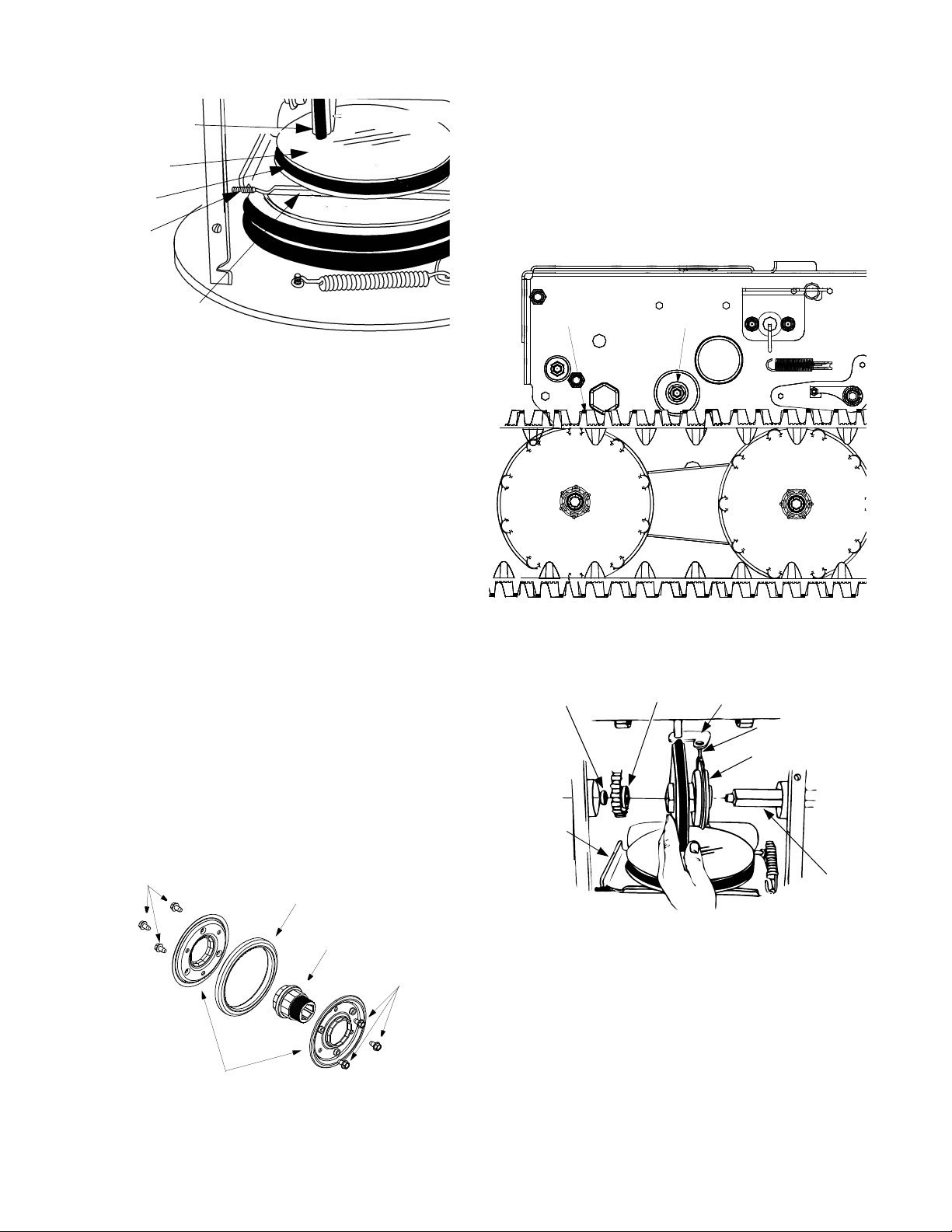
Friction Wheel
Drive Plate
Drive Belt
• Reassemble the new friction wheel rubber to the
friction wheel plates and hub, tightening the six
screws in rotation and with equal force.
• Position the friction wheel assembly up onto the pin
of the shift rod assembly, and slide the shaft
through th e asse mbly . Reas sembl e in re verse
order.
Stop Bolt
Support Bracket
Figure 18
Servicing Friction Wheel Rubber
The rubber on the friction wheel is subject to wear and
should be checked after 25 hours of operation, and
periodically thereafter. Replace the friction wheel
rubber if any signs of wear or cracking are found.
• Drain the gasoline from the snow thrower, or place
a piece of plastic under the gas cap.
• Tip the snow thrower up and forward, so that it rests
on the housing.
• Remove the six self-tapping screws from the frame
cover underneath the snow thrower.
• Using a 7/8" wrench to hold the shaft, loosen, but
do not completely remove, the hex bolt and washer
on the left end of the shaft. See Figure 19 and
Figure 20.
• Lightly tap the hex bolt to dislodge the ball bearing
from the right side of frame before removing the hex
bolt and washer from the left end of the shaft.
• Move the shaft to the right and slide the friction
wheel assembly from the shaft.
• Remove the six screws from the friction wheel
assembly (three from each side). Remove the
friction wheel rubber from between the friction
wheel plates. See Figure 18
NOTE: If you placed plastic film under the gas cap, be
certain to remove it.
Hex Bolt
Track
Spacer
Support
Bracket
Sprocket
Washer
Figure 20
Shift Rod
Assembly
Pin
Friction Wheel
Assembly
Screws
Friction Wheel Plates
Friction Wheel Rubber
Hub
Figure 19
Screws
Shaft
Figure 21
Off Season Storage
WARNING: Never store engine with fuel in tank
indoors or in enclosed, poorl y ventilated areas where
fuel fumes may r each an open flam e, spar k or pilot light
as on a furnace, wate r heater, clothes dryer, or other
gas appliance.
• Clean snow thrower thoroughly.
• Lubricate as instructed above with light oil.
15
Page 16

• Follow “Storage” instructions in the Engine Manual.
• Store in a clean, dry area. Block the snow thrower
up so it is not resting on the rubber auger blades.
NOTE: When storing an y type of po wer equipme nt in
an poorly ventilated or metal storage shed, care should
be taken to rustproof the equipment, especially springs,
cables and all moving parts.
SECTION 9: TROUBLE SHOOTING
Problem Cause Remedy
Engine fails to star t 1. Fuel tank empty, o r stale fuel.
2. Blocked fuel lin e.
3. Choke not in ON p osition
4. Faulty spark plug.
5. Safety key not in ignition switch on engin e.
6. Spark plug wire disconnected.
7. Primer button not being used properly.
8. Fuel shut-off valve closed.
Engine runs erratic 1. Unit running on CHOKE.
2. Blocked fuel lin e or stal e fuel.
3. Water or dirt in fue l system.
4. Carburetor out of adjustment.
Loss of power 1. Spark plug wire loose.
2. Gas cap vent hole plugged.
3. Exhaust port plugged .
Engine overheats 1. Carburetor not ad justed pro perly. 1. Refer to the engine manu al or have t he
Excessive vibration 1. Loose parts or da maged au ger. 1. Stop engine imme diately and disc onnect
Unit fail s
to propel itself
1. Traction contr ol cable in need of adjust ment.
2. Drive belt loose or damage d.
1. Fill tank with fresh gasoline.
2. Clean the fuel line.
3. Move switch to ON position
4. Clean, adjust gap or replac e.
5. Insert the key fully into the switch.
6. Connect spark plug wire.
7. Refer to the engine manu al.
8. Open fuel shut-off valve.
1. Move choke lever to OFF position.
2. Clean fuel line; fill tank with clean, fresh
gasoline.
3. Drain fuel tank an d carburetor. R efill wi th
fresh fuel.
4. Refer to the engine manu al.
1. Connect and tighten spark plug wire.
2. Remove ice and snow from gas cap . Be
certain vent hole is clear.
3. Refer to the engine manu al.
carburetor adjusted b y an aut horized
engine service deale r.
spark plug wire. Tighten all bolts and nuts. If
vibration continues, have unit serviced by
an authorized se rvice de aler.
1. Adjust traction c ontrol cab le. Ref er to page.
2. Replace drive belt. Refer to page 13.
Unit fail s
to discharge snow
Electric chute fails to
turn
Electric chute turns i n
opposite direction of
the switch
1. Discharge chute clogg ed.
2. Foreign object lodged in auger.
3. Auger control cable in need of adjustm ent.
4. Auger belt loose or damaged.
5. Shear bolt(s) sheared
1. Loose electrical connec tions.
2. Blown Fuse.
1. The switch co nnector i s instal led back wards 1. Unplug the switc h conne ctor under the
16
1. Stop engine imme diately and disc onnect
spark plug wir e. Clean discharge chute and
inside of auger housing.
2. Stop engine imme diately and disc onnect
spark plug wir e. Remo ve objec t from au ger.
3. Refer to page 6 for a djust ment instruc tions.
4. Refer to page 13.
5. Replace Shear bolt(s)
1. Make sure all connectio ns are tight and fully
installed.
2. Replace with #5A fuse. The fuse is under
handle panel ne ar switch con nector.
handle panel. Tu rn connector 180° and
reconnect.
Page 17

SECTION 10:
Models 724 STE / 926 STE
4
16
13
17
11
9
8
1
5
6
7
12
2
Ref.
No.
1.
2.
3.
4.
5.
6.
7.
8.
9.
10.
11.
12.
13.
14.
15.
16.
17.
18.
— 737-0168 Grease (Two Ounces)
Part No. Part Description
618-0123 RH Housing
618-0418 LH Housing w/Fitting
710-0642 Self Tapping Screw, 1/4-20 x .75
711-0908A
711-0909A
714-0161 Hi-Pro Key, 3/16 x 5/8
715-0143 Spring Spiral Pin, .25 x 1.25
717-0528 Worm Gear, 20-tooth
717-0526 Worm Shaft
718-0186 Thrust Collar
721-0325 Grease Plug
721-0327 Grease Seal
736-0351 Flat Washer, .76 x 1.5 x .030
736-0369 Flat Washer, .508 x 1.0 x .020
736-0445 Flat Washer, .76 x 1.5 x .060
741-0662 Flange Bearing, .75 x 1.0 x .59
741-0663 Flange Bearing, .503 ID x .75 OD
618-0414A
618-0415A
737-3000 Grease Fitting, 3/16” Drive
Spiral Axle, 24” (724 STE)
Spiral Axle, 26” (926 STE)
Gear Assy Complete, 24” (724 STE)
Gear Assy Complete, 26” (926 STE)
15
14
3
10
18
3
17
Page 18
Models 724 STE / 926 STE
68
67
37
50
25
31
39
91
For
reference
only
65
63
38
9
23
32
60
40
26
62
43
57
58
57
58
55
58
66
77
58
66
11
61
15
5
2
24
20
14
3
16
41
30
42
6
For
reference
only
44
9
27
35
35
36
48
10
49
44
28
12
19
9
7
14
78
14
53
56
64
76
79
45
5
10
7
88
11
69
27
80
75
9
51
10
83
92
82
31
40
46
27
74
45
47
21
85
84
4
86
87
52
10
14
27
18
5
70
5
1
22
11
59
72
73
72
27
71
68
69
54
81
29
8
13
17
11
15
90
89
18
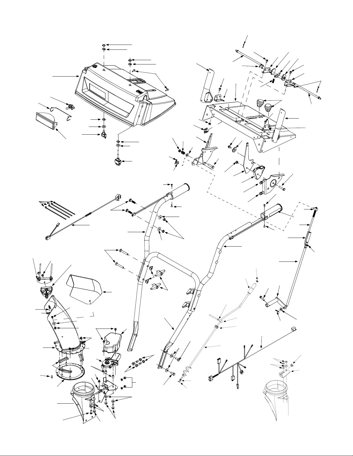
Page 19

Models 724 STE / 926 STE
Ref.
No.
1.
2.
3.
4.
5.
6.
7.
8.
9.
10.
11.
12.
13.
14.
15.
16.
17.
18.
19.
20.
21.
22.
23.
24.
25.
26.
27.
28.
29.
30.
31.
32.
35.
36.
37.
38.
39.
40.
41.
42.
43.
44.
45.
46.
47.
48.
Part No. Part Description
684-0008A Shift Arm Assembly
710-0262 Carriage Bolt 5/16-18 x 1.5”
710-0449 Carriage Bolt 5/16-18 x 2 .25”
710-0788 TT Screw 1/4-20 x 1”
710-0837 C-Sunk Screw #10-16x .625Ӡ
710-0890A Shear Bolt 5/16-18 x 1.5”
710-3008 Hex Screw 5/16-18 x .7 5”
711-0677 Ferrule
712-0429 Hex Lock Nut 5/16-18
712-3010 Hex Nut 5/16-18
714-0104 Cotter Pin
720-0284 Handle Knob
720-0274
725-1757
736-0242 Belleville Washer
736-0275 Flat Washer
736-0451 Saddle Washer
747-0620A Shift Rod: Upper
747-0621 Shift Rod: Lower
749-0951 Lower Handle
749-0952A Upper Handle: L Style RH
749-0953A Upper Handle: L Style LH
750-0963 Connector: Shift Rod
618-0419 Gear Assembly: Ring ‡
629-0937 Electric Harness: Lower ‡
710-0262 Carriage Bolt: 5/16-18 x 1.5”
710-0451 Carriage Bolt: 5.16-18 x .750”
710-0599 TT Screw: 1/4-20 x 0.5”
710-0602 TT Screw: 5/16-18 x 1” ‡
710-0805 Hex Screw: 5/16-18 x 1.5”
710-0817 TT Screw: 5/16-18 x 1. 25” ‡
710-0896 Hex Screw AB:1/4-14 x 0.625 ”
710-3008 Hex Screw: 5/16-18 x .75” ‡
712-3027 Hex Flange Lock Nut
724-0249 Electric Motor: Chute Crank ‡
725-0157 Cable Tie
731-0851A Chute Flange Keeper
731-1300A Lower Chute
731-1313C Cabl e Guide: C hute Tilt
731-1320 Upper Chute
731-2279 Motor Cover: Chute Rotation ‡
736-0159 5/16 Washer
736-0242 Belleville Washer ‡
736-0506 Special Washer
746-0896 Control Cable
746-0901 Control Cable
750-1232 Spacer‡
Grip†
Heated Grip ‡
19
Ref.
No.
49.
50.
51.
52.
53.
54.
55.
56.
57.
58.
59.
60.
61.
62.
63.
64.
65.
66.
67.
68.
69.
70.
71.
72.
73.
74.
75.
76.
77.
78.
79.
80.
81.
82.
83.
84.
85.
86.
87.
88.
89.
90.
91.
92.
Part No. Part Description
782-0599 Motor Bracket‡
784-5594 Cable Bracket
784-5604 Handle: Chute Tilt
629-0936
629-0938A
684-0036 Handle Assembly RH
684-0037A Handle Assembly LH
710-1003 Special Hex Screw
712-0271 Hex Sems Nut: 1/4-20
712-0693 Hex Nut‡
716-0398 Lock Ring: Toggle Switch‡
720-0232 Shift Knob
725-1672 Lamp Housing
725-1755 Toggle Switch: Double Thr.‡
725-1756 Toggle Switch: Single Thr.‡
725-1759 Halogen Lamp: 50 W, 12V
726-0152 Mounting Clamp‡
731-2276
731-2274
736-0226 Flat Washer†
747-1136 Headlight Retain er
714-0507 Cotter Pin: 3/32 x .75
747-0877 Cam Rod
784-5680 RH Handle Support B racket
784-5679 LH Handle Support Brac ket
748-0362 Cam Handle Loc k
748-0363 Handle Lock Pawl
732-0145 Compression Sprin g: .36 x 1.0
710-0459A Hex Cap Screw: 3/8-24 x 1.5
784-5619A Shift Handle
712-0116 Jam Nut, 3/8-24
732-0193 Comp. Spring: .39 x .6 x .88
736-0105 Bell Washer
784-5682 RH Handle Support B racket
784-5681 LH Handle Support Brac ket
711-0653 Clevis Pin
705-5204A Chute Crank Assembly †
720-0201A Knob †
726-0100 Push Cap †
747-0697 Eyebolt †
735-0234 Rubber Grommet †
736-0185 Flat Washer†
784-5647 Chute Crank Brkt.†
741-0475 Plastic Bushing†
710-3015 Hex Head Cap Screw 1/4-20†
684-0102 Handle Panel
Harness Assembly: Uppe r‡
Harness Assembly: Light †
Handle Pane‡
Handle Panel†
† 724 STE
‡ 924 STE
Page 20

Models 724 STE / 926 STE
38
18
34
2
3
4
11
10
15
14
27
28
9
13
35
12
13
25
10
9
16
23
22
26
30
19
1
5
6
7
8
21
23
22
39
40
42
37
18
36
41
39
29
16
20
31
32
33
17
40
24
20
Page 21
Models 724 STE / 926 STE
Ref.
No.
1.
2.
3.
4.
5.
6.
7.
8.
9.
10.
11.
12.
13.
14.
15.
16.
17.
18.
19.
20.
21.
22.
Part No. Part Description
712-0116 Lock Jam Nut 3/8 -24
756-0178 Flat Idler
784-5632A Auger Idler Arm
710-0459A Hex Cap Screw 3/8-24 x 1.50
738-0281 Shoulder Screw
736-0167 Flat Washer
732-0611 Extension Spring
712-3068 Hex Nut 5/16-18
710-0276 Carriage Bolt, 5/16-18 x 1.00
736-0119 Lock Washer 5/16
05931A Housing
741-0309 Ball Bearing
710-0451 Carriage Bolt, 5/16-18 x .75
705-5226 Chute Reinforcement
684-0039C
684-0040C
712-3010 Hex Nut 5/16-18
712-0429 Lock Nut 5/16-18
736-0242 Belleville Wash er
736-0231 Flat Wshr, .344ID x 1.125 O D
737-3000 Grease Fitting, 3/ 16” Drive
731-1379B Chute Adapter
712-0324 Hex Lock Nut 1/4-20
24” Housing Assy (724 STE)
26” Housing Assy (926 STE)
Ref.
No.
23.
24.
25.
26.
27.
28.
29.
30.
31.
32.
33.
34.
35.
36.
37.
38.
39.
40.
41.
42.
Part No. Part Description
736-0463 Flat Washer
784-0399 Bearing Housing w /Fitting
710-0703 Carriage Screw 1/4-20 x .7 5
710-0604 Hex Screw 5/16-18
736-0169 Lock Washer 3/8
712-0798 Hex Nut 3/8-16
741-0245 Hex Flange Bearing
784-5038B Skid Shoe
736-0242 Bell Washer
712-3010 Hex Nut 5/16-18
784-5581A
784-5579A
710-0260 Carriage Bolt 5/16-18 x .62
684-0065 Impeller Assembly
715-0114 Pin
618-0414A
618-0415A
605-5188A
605-5192A
736-0188 Flat Washer
741-0493A Flange Bushing
605-5189A
605-5193A
710-0890A Shear Bolt 5/16-18 x 1.5
Shave Plate (724 STE)
Shave Plate (926 STE)
24” Gear Assy (724 STE)
26” Gear Assy (926 STE)
24” Spiral RH (724 STE)
26” Spiral RH (926 STE)
24” Spiral LH (724 STE)
26” Spiral LH (926 STE)
NOTE: For painted parts, please refer to the list
of color codes below. Please add the applicable
color code, wherever needed, to the part number
to order a replacement part. For instance, if a
part, numbered 700-xxxx, is painted Cub Yellow,
the part number to order would be 700-xxxx-0716.
Cub Yellow: 0716
Cub Beige: 0499
Powder Black: 0637
21
Page 22

Models 926 STE
28
29
30
26
23
22
21
16
19
16
16
19
16
15
11
12
10
18
17
27
14
1
3
4
8
9
13
7
4
6
5
1
2
24
25
20
IMPORTANT: For a proper working machine, use Factory
Approved Parts.
V-BELTS are specially designed to engage and disengage
safely. A substitute (non OEM) V-Belt can be dangerous by
not disengaging comp letely
22
Page 23

Models 926 STE
Ref.
No.
1.
2.
3.
4.
5.
6.
7.
8.
9.
10.
11.
12.
13.
14.
15.
16.
17.
18.
19.
20.
21.
22.
23.
24.
25.
26.
27.
28.
29.
30.
Part No. Part Description
710-1652 Hex Washer Screw 1/4-20 x .625
731-1324 Belt Cover
732-0710 Extension Spring
710-0627 Hex Screw 5/16-24 x .7 5
710-3005 Hex Cap Screw 3/8-16 x 1.25
05896A Drive Clutch Idler Bracket
748-0234 Shoulder Spacer
756-0987 Pulley Half
754-0346 V-Belt
756-0986 Pulley Half
736-0270 Bell Washer
710-0230 Hex Cap Screw 1/4-28 x .50
756-0313 Flat Idler
710-1245 Lock Hex Cap Screw 5/ 16-24
712-0181 Lock Jam Nut 3/8-1 6
756-0569 Pulley Half
736-0242 Bell Washer
736-0505 Flat Washer
754-0430A Belt
756-0967 Auger Pulley
736-0247 Flat Washer 3/8 x 1 .25 OD
736-0331 Bell Washer
710-0696 Hex Cap Screw 3/8-24
748-0360 Adapter Pulley
710-0654A Hex Screw 3/8-16 x 1.0
629-0071 Extension Cord
OEM-390-987 Electric Start Kit
712-0324 Lock Nut, 1/4-20
736-0173 Flat Washer, .28 x .74 x .063
732-0705 Cable Guide
23
Page 24

Model 724 STE
1
32
5
16
14
24
21
24
23
9
15
2
28
11
3
27
22
26
2
3
20
8
12
1
29
30
31
19
6
13
17
18
25
IMPORTANT: For a proper working machine, use Factory
Approved Parts.
V-BELTS are specially designed to engage and disengage
safely. A substitute (non OEM) V-Belt can be dangerous by
not disengaging completely
24
4
Page 25

Model 724 STE
Ref.
No.
1.
2.
3.
4.
5.
6.
7.
8.
9.
10.
11.
12.
13.
14.
15.
16.
17.
18.
19.
20.
21.
22.
23.
24.
25.
26.
27.
28.
29.
30.
31.
32.
Part No. Part Description
05896A Drive Clutch Idler Bracket
710-0230 Hex Cap Screw 1/4-20
710-0627 Hex Cap Screw 5/16-24
710-0654A Hex Screw 3/8-16 x 1.0
710-0696 Hex Cap Screw 3/8-24
710-1245 Lock Hex Cap Screw 6/16-24
710-1652 Hex Washer Screw 1/4-20 x .625
710-3005 Hex Cap Screw 3/8-16 x 1.25
712-0181 Lock Jam Nut 3 /8-16
731-1324 Belt Cover
732-0339 Extension Spring
736-0159 Washer 5/16
736-0242 Bell Washer
736-0247 Flat Washer
736-0270 Bell Washer
736-0331 Bell Washer
736-0505 Flat Washer
736-0507 Special Wash er
748-0360 Adapter Pulley
750-1053 Spacer
754-0430A Belt
754-0456 V-Belt
756-0313 Flat Idler
756-0569 Pulley Half
756-0967 Auger Pulley
756-0984 Pulley Half
756-0985 Pulley Half
OEM-390-987 Electric Start Kit
712-0324 Lock Nut, 1/4-20
736-0173 Flat Washer, . 28 x .74 x .06 3
732-0705 Cable Guide
629-0071 Extension Cord
25
Page 26
Models 724 STE / 926 STE
22
23
24
25
19
21
20
19
18
17
16
14
3
15
26
11
13
29
27
28
30
31
36
18
32
2
30
20
26
19
10
19
27
2
30
34
32
25
24
23
22
2
21
12
4
1
9
7
6
5
39
38
32
2
40
32
37
26
Page 27
Models 724 STE / 926 STE
Ref.
No.
1.
2.
3.
4.
5.
6.
7.
8.
9.
10.
11.
12.
13.
14.
15.
16.
17.
18.
19.
20.
Part No. Part Description
784-5648 Frame C o ver
710-1652 Tap Screw, 1/4-20 x .625
748-0190 Spacer, .508 ID x .75 OD x .68
732-0264 Ext. Spring
712-0711 Jam Nut, 3/8-24
736-0105 Bell Washer, .401 x .87 x .063
684-0021 Friction Wheel Supp ort Bracket Assy
746-0898 Drive Cable, 39.88”
656-0012A Friction Disc
784-5689A Front Support Guide Bracket
713-0413 Ten-Tooth Sprocket
746-0897 Auger Cable, 44.75”
750-0997 Spacer, .675 ID x 1 OD x .23
711-1042 Hex Track Shaft
684-0042C Friction Wheel Assembly
736-0160 Flat Washer, .536 ID x .93 OD x .05
714-0474 Cotter Pin
741-0563 Ball Bearing
736-0242 Bell Washer, .34 ID x .872 OD
710-0538 Hex Cap Screw, 5/16-18 x .625
Ref.
No.
21.
22.
23.
24.
25.
26.
27.
28.
29.
30.
31.
32.
33.
34.
35.
36.
37.
38.
39.
40.
Part No. Part Description
710-0875 Tap Screw, 1/4-20 x .75
736-0270 Bell Washer, .265 x .75 x .062
736-0176 Flat Washer, 1/4 ID x .93 OD x .12
741-1111 Hex Flange Bearing
710-0643 Hex Cap Screw, 5/16-18 x 1
748-0234 Shoulder Spacer
710-0604 Tap Screw, 5/16-18 x .625
684-0031 Frame Assembly
738-0924 Spacer
756-0625 Cable Roller
784-5688 Drive Cable Guide Br acket
710-0599 Tap Screw, 1/4-20 x .5
784-5590 Shift Frame Bracket
684-0014B Shift Rod Assembly
784-5687A Auger Cable Guide Bracket
710-0809 Tap Screw, 1/4-20 x 1.25
618-0063 Friction Wheel Bearing
718-0301A Friction Wheel Hub
735-0243 Friction Wheel Rubber
784-5617A Friction Plate
NOTE: For painted parts, please refer to the list
of color codes below. Please add the applicable
color code, wherever needed, to the part number
to order a replacement part. For instance, if a
part, numbered 700-xxxx, is painted Cub Yellow,
the part number to order would be 700-xxxx-0716.
Cub Yellow: 0716
Cub Beige: 0499
Powder Black: 0637
27
Page 28

Models 724 STE / 926 STE
44
43
14
4
8
13
40
30
42
11
39
27
45
54
52
22
48
32
50
33
28
29
46
47
20
51
49
30
53
56
37
31
19
24
16
12
51
46
19
54
55
20
26
25
1
2
3
5
9
6
10
7
15
17
18
21
36
34
33
38
41
35
32
23
37
56
22
26
21
18
14
28
17
16
15
13
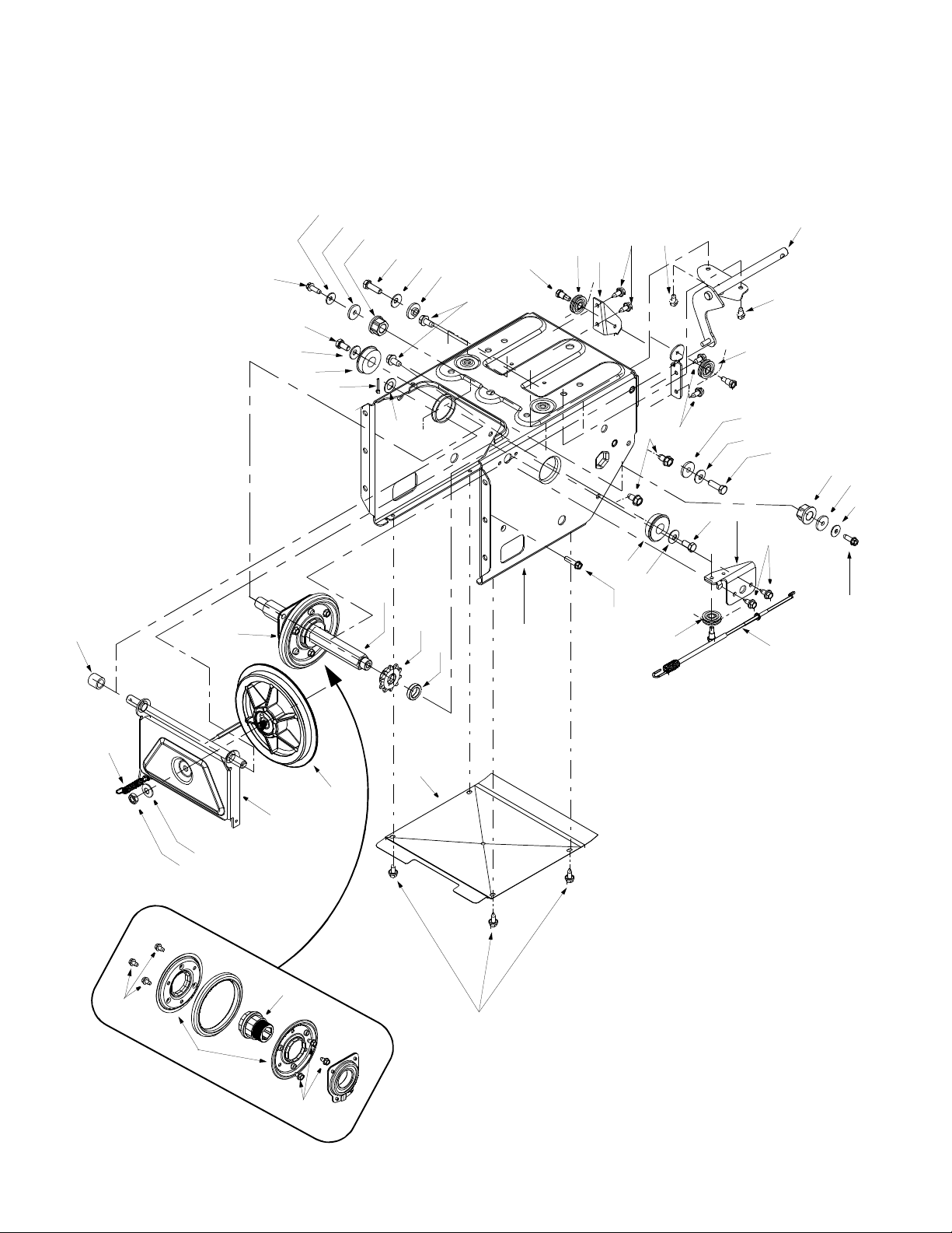
Page 29

Models 724 STE / 926 STE
Ref.
No.
1.
2.
3.
4.
5.
6.
7.
8.
9.
10.
11.
12.
13.
14.
15.
16.
17.
18.
19.
20.
21.
22.
23.
24.
25.
26.
27.
28.
Part No. Part Description
720-0223 Grip
710-0604 Tap Screw, 5/16-18 x .625
784-5642 Track Lockout Plate
710-0157 Hex Cap Screw, 5/16-24 x .75
736-0242 Bell Washer, .34 ID x .872 OD
684-0038 Track Lock Handl e Assem bly
710-0459A Hex Cap Screw, 3/8-24 x 1.5
712-0214 Hex Nut, 3/8-24
748-0353A Lift Shaft Drive
750-0547 Spacer, .628 ID x .875 OD x .5
784-5609 Steering Cable Bracket
684-0009 Track Pivot Rod Assembly
712-0346 Jam Nut, 1/2-20
731-1292 Snow Track
736-0272 Flat Washer, .5 x 1 x .06
731-1538A Track Drive Wheel
631-0032 Track Idler Wheel
750-0995 Spacer, .51 ID x .75 O D x 1.67
738-0140 Screw, .435 x .178-5/16 x .56
736-0406 Flat Washer, .442 x 1.38 x .06
750-0909 Spacer, .51 ID x 1 OD x 1.34
712-0429 Hex Nut, 5/16-18
618-0044 LH Dogg Assembly
684-0024 Idler Axle Assembly
710-1231 Eye Bolt, 5/16-18 x 3
784-5639 Track Side Plate
711-0911 Actuator Shaft
713-0233 Chain
Ref.
No.
29.
30.
31.
32.
33.
34.
35.
36.
37.
38.
39.
40.
41.
42.
43.
44.
45.
46.
47.
48.
49.
50.
51.
52.
53.
54.
55.
56.
Part No. Part Description
618-0169 Track/Steering Shaft Assy
684-0154 Track Hub Assy w/Fittin g
713-0437 Chain
741-0339 Flange Bearing
736-0287 Flat Washer, .793 x 1 .24 x .06
611-0053 Axle Assembly
750-0904 Spacer, .514 x .630 x 1.59
618-0043 RH Dogg Assembly
750-0903 Spacer, .514 x .630 x 2.44
732-0209 Ext. Spring
710-0602 Tap Screw, 5/16-18 x 1
719-0295A Track Housing
746-0948 Steering Cable
746-0950 Steering Trigger
712-0127 Flange Nut
710-1233 Screw, #10-24 x 1.375
716-0114 Retaining Ring
618-0046 Carrier Assembly
717-1211 Ring Gear
716-0115 Retaining Ring
713-0414 13-Tooth Sprocket
711-0912 Track Steering Drive Shaft
736-0502 Flat Washer, .58 x 1.0 6 x .02
736-0336 Flat Washer, 5/8 x 1 x .03
715-0120 Spiral Pin, 3/16 x 1
717-1209 12-Tooth Gear
717-1210 18-Tooth Gear
737-3000 Grease Fitting , 3/16” Drive
NOTE: For painted parts, please refer to the list
of color codes below. Please add the applicable
color code, wherever needed, to the part number
to order a replacement part. For instance, if a
part, numbered 700-xxxx, is painted Cub Yellow,
the part number to order would be 700-xxxx-0716.
Cub Yellow: 0716
Cub Beige: 0499
Powder Black: 0637
29
Page 30

MANUFACTURER’S LIMITED WARRANTY FOR:
TWO-YEAR RESIDENTIAL
ONE-YEAR COMMERCIAL
Proper maintenance of your Cub Cad et equi pm ent is the own er’s responsibility. Follow the instructions in your
operator’s manual for correct lubricants and maintenance schedule. Your Cub Cadet dealer carries a
complete line of quality lubricants and filters for your equipment’s engine, transmission, chassis and
attachments.
Riding mowers, lawn tractors, garden tractors, Cub Cadet
attachments and home maintenance products
This limited warra nty for residential users, covers a ny defect in mater ials or workmansh ip in your Cub Cadet
equipment for two years from the dat e of purchase for the firs t user purchase r. We will replace or repa ir any
part or parts without charge through your authorized Cub Cadet dealer.
Batteries have a one-year prorated limited warranty with 100% replacement during the first three months.
V-belts for either the traction drive or any attachments are covered for one year only.
Cub Cadet equipment used commercially is warranted for one year only.
(Commercial use is defined as either having hired operators or used for income producing purposes.)
Items not covered
The warranty doe s not c over rout ine ma intena nce i tems suc h as lubri cants, f ilt ers (o il, fue l, air a nd h ydraul ic),
cleaning, tune-ups, br ake and/or clutch inspection, a djustments made as part of normal maintenance, blade
sharpening, set-up, a bus e, a ccid ent s and normal wear. It doe s n ot c ov er in ci den tal cos ts suc h as tr anspo rti ng
your equipment to and from the dealer, telephone charges or renting a product temporarily to replace a
warranted product.
There is no other express warranty.
How to obtain service
Contact your autho riz ed Cub Ca det s ervi cing de ale r who s old you your Cub Ca det eq uip men t. I f th is d eal er i s
not available, see the Consumer Yellow Pages under “lawn mowers” for the name of a dealer near you.
If you need further assistance in finding an authorized Cub Cadet servicing dealer, contact:
Cub Cadet Corporation
Post Office Box 368023
Cleveland, Ohio 44136
How does state law apply?
This limited warranty gi ves y ou spec ific lega l rig hts, and you m ay als o have ot her right s which va ry from s tate
to state.
 Loading...