

Page 1

&
*36123
18(4VSHYGXW%OXMIRKIWIPPWGLEJX¤7EEVFVµGOIR¤+IVQER]
SERIES 7000
Page 2

English
Français
Deutsch
Page 3

TABLE OF CONTENTS
TO THE OWNER ..................................... ....... ...... ....... ...... ...... ............................................... 3
CALLING SERVICE INFORMATION ...................................................................................... 3
RECORDING MODEL AND SERIAL NUMBER INFORMATION ........................................... 4
USING THE TRACTOR CORRECTLY..................................................................................... 5
IMPORTANT SAFE OPERATION PRACTICES ..................................................................... 6
SAFETY LABELS ................................................................................................................. 10
SECTION 1: CONTROLS AND FEATURES ........................................................................ 12
SECTION 2: OPERATION .................................................................................................... 18
SECTION 3: ADJUSTMENTS .............................................................................................. 27
SECTION 4: TRACTOR MAINTENANCE ............................................................................ 30
SECTION 5: ENGINE INFORMATION AND MAINTENANCE ............................................. 43
SECTION 6: SPECIFICATIONS ........................................................................................... 49
SECTION 7: OPTIONAL EQUIPMENT AND ACCESSORIES ............................................. 50
WARRANTY ..................................... ...... ....... ...................................................................... 51
TO THE OWNER
This Operator’s Manual is an important part of your new tractor. The information contained in this
manual has been prepared in detail to help you better understand the features, correct operation,
adjustments, and mainten ance of your tractor. The performance and dependa bility of this trac tor rely
greatly on the manner in which it is operated and maintained. Therefore, it i s recommended that all
operators of the tracto r carefully read this manua l and fully understand its operation. Also keep the
manual available for reference to ensure proper operation, and that maintenance procedures are
performed as scheduled to assure the tractor’s optimal mechanical condition.
NOTE:
indicate that relative position on the tractor when facing forward while seated in the operator’s seat.
Your authorized
with the maintenance needed to ensure the satisfactory operation of your tractor. The dealer has
trained service personnel familiar with the latest servicing information, is equipped with the latest
tools, and has a comple te line of genuine
quality.
All references to LEFT, RIGHT, FRONT, and REAR, unless specifically stated otherwise,
Cub Cadet
dealer is interested i n the perfo rmanc e you re ceiv e from yo ur trac tor, an d
Cub Cadet
service parts wh ich assure proper fit and high
CALLING SERVICE INFORMATION
The engine manufacturer is responsible for all engine-related issues with regards to performance,
power-rating, and specifications.
If you have difficulties with the tractor and/or eq uipment; have any q uestions regarding th e operation
or maintenance of t his equipment; or desire additio nal information not found in th is manual, contact
your dealer. If you need assistance in locating a deal er in your area, contact the Cust omer Dealer.
Before calling your dealer, make sure that you have y our model number(s) and manufa cturing date
available for the dealer.
3
Page 4
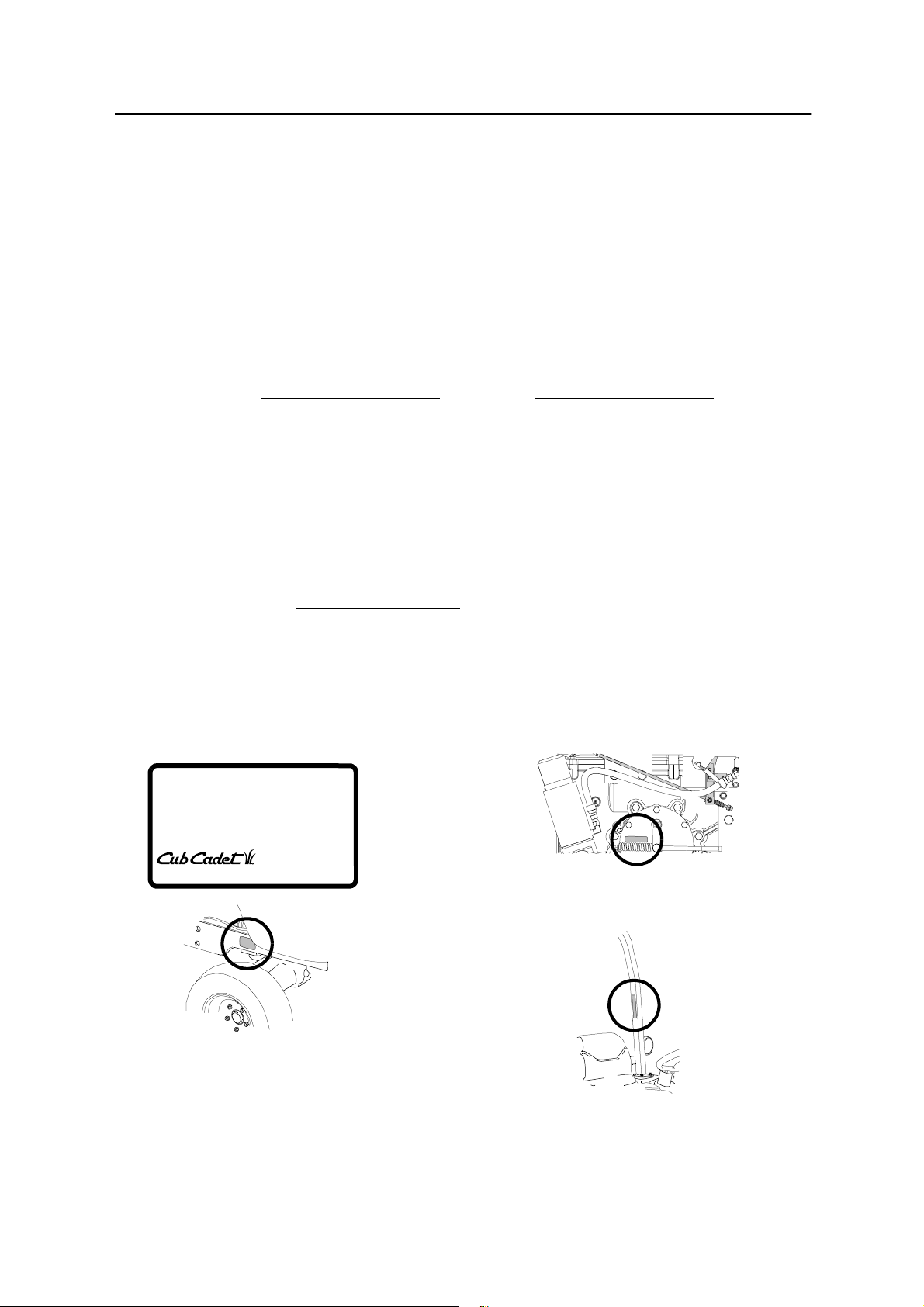
RECORDING MODEL AND SERIAL NUMBER INFORMATION
Product identification plates are provided for major components of your tractor. The numbers on these
plates are importa nt if you r tractor should re quire de aler se rvice, or i f you nee d additio nal infor mation
on your tractor. Prior to usin g your tracto r for the fir st time, r ecord the nu mbers from the ident ification
plates in the appropriate spaces provided below.
• The tractor model plate is located on the right frame rail behind the right front tire.
• The engine model/ serial number plate and engin e information plate are loc ated on the right side
of the engine above and aside the injection pump (below the air cleaner).
• The transmission serial plate is located on right brake drum cover behind the right rear wheel.
• The ROPS information plate is located on the left vertical leg of the ROPS.
Tractor Model Plate:
Model Number Mfg. Date (Serial No.)
Engine Information:
Engine Model Serial Number
Transmission Serial Plate:
Serial Number
ROPS Information Plate:
ROPS Serial No.
TRACTOR MODEL PLATE
XXXXXXXXXXX XXXXXXXXXX
Model Number Mfg. Date
CUB CADET LLC
P. O. BOX
www.cubcadet.com
DEALER LOCATOR PHONE NUMBER:
361131
CLEVELAND, OH 44136
877-282-8684
TRANSMISSION SERIAL PLATE
ROPS INFORMATION PLATE
4
Page 5

USING THE TRACTOR CORRECTLY
This tractor is intended for use
• As a tractor for usual emp loyment in the land- and forestry, green areas- and plant c are as well as for
winter services.
• In accordance with the instructions and safety information contained in this guide.
Any other use is considered to be contrary to the inten ded purp ose. The u ser is l iable for all dama ge done t o
third parties and to their property on the part of the manufacturer for damage resulting therefrom.
WARNING: This tractor is not licensed for use on public roads and public surfaces within its
standard configuration. When using public traffic roads and public surfaces the tractor
respective regulations of the country the is used in have to be considered.
5
Page 6

IMPORTANT SAFE OPERA TION PRACTICES
WARNING: THIS SYMBOL POINTS OUT IMPORTANT SAFETY INSTRUCTIONS WHICH, IF
NOT FOLLOWED, COULD ENDANGER THE PERSONAL SAFETY AND/OR PROPERTY OF
YOURSELF AND OTHERS. READ AND FOLLOW ALL INSTRUCTIONS IN THIS MANUAL
BEFORE ATTEMPTING TO OPERATE YOUR UNIT. FAILURE TO COMPLY WITH THESE
INSTRUCTIONS MAY RESULT IN PERSONAL INJURY. WHEN YOU SEE THIS SYMBOL,
HEED ITS WARNING.
WARNING: The engine exhaust, some of its constituents, and certain vehicle components
contain or emit che micals known to the State o f California to cause cance r, birth defects or other
reproductive harm.
DANGER: Your tractor was built to be operated according to the rule s for safe operation in this
manual. As with any type of power equip ment, c areles sness or error on th e par t of the operato r ca n
result in serious injury. To help prevent accid ents, read and take the f ollowing precautions before
operating this tractor. Failure to observe the following safety instructions could result in serious
injury or death.
1. GENERAL OPERATION
• Read, understand , and follow all instructi ons in
the operator’s manual and on the machine
before starting. Keep this manual in a safe
place for future and regular reference.
• Only allow res ponsible individuals familiar with
the instructions to operate the machine. Know
controls and how to stop the machine quickly.
• Use the roll bar and seat belt for safe operation.
Overturning the tractor without a roll bar, or with
a roll bar and the seat belt unfastened, can
result in death or injury.
• Always use the seat belt, except if the roll bar
has been removed or, if applicable, the roll bar
is in the folded position.
• Use the handholds and running boards when
getting on and off the tractor to help prevent
accidental falls. Keep the running boards cl ear
of mud and debris.
• Wear sturdy, rough-soled work shoes. Never
operate the tractor in bare feet, sandals, or
sneakers.
• Do not wear loose fitting clothes or jewelry.
They can be caught in moving parts.
• Do not allow anyo ne but the o perator to r ide on
the tractor. There is no safe position on the
tractor for additional riders. Do not carry
passenger.
• Keep all safety decals clean and readable.
Replace any missing, illegible, or damaged
safety decals.
• Do not operate the machine while under the
influence of alcohol or drugs.
• Use only accessories approved for this
machine by the manufacturer. Read,
understand and fol low all instructions provided
with the approved accessory.
• Before starting the tractor, engage the parking
brake, place the PTO switch in the "OFF"
position, place the li ft control lever in the down
position, and make certain any remote control
valve levers are in the neutral position.
• Always sit in the tractor seat when starting the
engine or operating controls. Do not start the
engine or operate controls while standing
beside the tractor.
• Never tamper with safety devices. Chec k their
proper operation regularly. Contact your Cub
Cadet dealer if safety devices malfunction.
• Avoid accidental contact with control pedals
while the engine is runni ng, as this can cause
unexpected movement of the tractor.
• Never leave a running machine unattended.
Always disengage the PTO, engage the
parking brake, and stop engine before
dismounting.
• Never park the tractor on a steep incline.
• Pull only from a drawbar or the l ower h itch lin ks
in the down position. Mak e certain the drawbar
pin is locked in p lace. Pull ing from the rea r axl e
of the tractor or any point abov e the axle could
cause the tractor to overturn.
• Maintain the weight balance of the tractor.
Install front end weights to counterbalance
heavy implements attached to the three point
hitch. Do not operate the tractor with a light
front end.
6
Page 7

• Any towed vehicle with a total weight exceeding
that of the tractor should be equipped its own
braking system that is operational from the
tractor seat.
• Do not leave equipment in the raised position.
• Watch for traffic when operating near or
crossing roadways. If local laws permit road
travel, use the flashing hazard lights and SMV
signs when traveling on public roadways.
• Make certain all tractor lights are illuminated
when operating at night.
• Always watch where you are going, espe cially
at blind corners, trees, or other objec ts that ca n
obscure your vision.
• Check overhead clearance carefully before
driving under power l ines, wires, bridge s or low
hanging tree branches, before entering or
leaving buildings, or in any other situation
where the operator and/or roll bar may be
struck, which could result in serious injury.
• To avoid upsets , drive the tracto r with care an d
at a safe speed. Use extra caution when
operating over rough ground, when crossing
ditches or slopes, and when turning corners.
• If the tractor becomes stuck, use reverse to
free the tractor to prevent tractor upset.
2. SLOPE OPERATION
Slopes are a maj or factor related to los s of control
and tip-over accidents which can result in severe
injury or death. All slopes require extra caution. If
you cannot back up the slope or if y ou feel uneasy
on it, do not operate this unit on that area or serious
injury could result.
DO:
• Operate up and down slopes, not across.
• Remove obstacles such as rocks, limbs, etc.
• Watch for holes , ruts or bumps. U neven terrain
could overturn the mac hine. Tal l grass can hid e
such obstacles.
• Place the transmi ssion in the low range. when
climbing or descending slopes. Always keep
machine in gear when going down slopes to
take advantage of engine braking action.
• Follow the manufa cturers recommendations for
counterweights to improve stability.
• Keep all movement on the slopes slow and
gradual. Do not make sudden changes in
speed or direction. Rapid engagement or
braking could cause t he front of the machine to
lift and rapidly fli p over backwards which coul d
cause serious injury.
• Avoid starting or stopping on a slope. If tires
lose traction, disen gage the PTO and proceed
slowly straight down the slope.
DO NOT:
• Do not turn on slope s unless necessary; then,
turn slowly and gradually downhill, if possible.
• Do not mow near drop-offs, ditches or
embankments. The mower coul d suddenly turn
over if a wheel goes over the edge of a cliff or
ditch, or if an edge caves in.
3. CHILDREN
• Tragic accide nts ca n occu r if the oper ator i s not
alert to the presence of children. Children are
often attracted to the machine. Never assume
children will remain where you last saw them.
• Keep childr en out of the operating area an d in
watchful care of an adult other than the
operator.
• Be alert and turn machine off if children enter
the area.
• Before and when backing, look behind and
down for small children.
• Never carry children . They may fal l off and be
seriously injur ed or interfere with safe machin e
operation.
• Never allow children under 16 years old to
operate the machine. Bylaws may stipulate a
different minimum age. Children 16 years and
over should only op erate machine under close
parental supervision and proper instruction.
• Use extra care when approaching blind
corners, shrubs, tree s or other o bjects tha t may
obscure your vision of a child or other hazard.
• Remove key when machine is unattended to
prevent unauthorized operation.
4. OPERATING THE PTO
• When operating PTO driven equipment,
disengage the P TO, stop the engine, and wait
until the PTO stops before dismounting the
tractor and disconnecting the equipment.
• Do not wear loose fitting clothing when
operating the PTO or when near rotating
equipment.
7
Page 8

• To prevent injury, do no t adjust, unclog, clean,
or service PTO driven equipment while the
tractor engine is running.
• Make certain all PTO shields are always installed.
5. SAFETY FRAME (ROPS)
Your tractor is equipped with a rollover protective
structure (ROPS) which must be maintained in a
fully functional condition. Use care when driving
through doorways or spaces with a low overhead.
• Never modify the ROPS in any way.
• Never attempt to s traighten or reweld any part
of the main frame or retaining brackets that
have been damaged. Doing so may weaken
the structure and endanger your safety.
• Never secure any parts on the main frame or
attach the safety frame wi th a ny thi ng othe r tha n
the special fasteners specified.
• Never attach ropes, chains, or cables to the
ROPS for pulling purposes.
• Although the ROPS provides you the maximum
protection possible, never take unnece ssary risks.
6. SERVICE
• Use extreme care in handling gasoline and
other fuels. They are extremel y flammable and
the vapors are explosive. Us e onl y an app ro ve d
container.
• Never remove fuel cap or add fuel with the
engine running.
• Replace fuel cap securely and wipe off any
spilled fuel befor e starting the engine a s it may
cause a fire or explosion.
• Extinguish all cigarettes, cigars, pipes and
other sources of ignition.
• Never refuel th e machine indoors becau se fuel
vapors will accumulate in the area.
• Never store the fuel container or machine
inside where there is an open flame or spark,
such as a gas hot water heater, space heater
or furnace.
• The cooling system is under pressure. Never
remove the radiator cap when the system is
hot. Slowly turn the cap the to the first stop to
release pressure before removing the cap.
• Escaping hydraulic fluid under pressure can
penetrate the skin. If fluid is injected into the
skin, seek immedia te medical attention. Do not
use your hand to check for lea ks. Use a piece
of cardboard or paper.
• Never run a machine inside a closed area.
• To reduce fire hazard, keep the tractor free of
any debris build-up. Clean up oil or fuel spillage.
• Before cleaning, repairing or inspecting, make
certain all movi ng parts have s topped. Keep all
nuts, bolts and screws tight to be sure the
equipment is in safe working condition.
• Never tamper with safety devices. Chec k their
proper operation regularly.
• Check brake operation frequently. Adjust and
service as required.
• Engine components become hot during
operation and can caus e a burn. Allow to cool
down before touching.
• Do not change the engine governo r settings or
overspeed the engine. Excessive engine
speeds are dangerous.
• Observe prop er disposal laws and regulations.
Improper disposal of fluids and materials can
harm the environment and the ecology.
• Prior to disposal, de termine the proper method
to dispose of waste from your local
Environmental Protection Agency. Recycling
centers are established to properly dispose of
materials in an environmentally safe fashion.
• Use proper co ntainers when dr aining fluids. D o
not use food or beverage containers that may
mislead someone into drinking from them.
Properly dispose of the conta iners immediately
following the draining of fluids.
• DO NOT pour oi l or other fluids into the ground ,
down a drain or into a stream, pond, lake or
other body of water. Observe Environmental
Protection Agency regulations when disposing
of oil, fuel, coolant, brak e fluid, filter s, batteries,
tires and other harmful waste.
• We do not recommend the use of a pressure
washer or garden hose to clean you r unit. They
may cause damage to electrical components;
spindles; pulleys; bearings; or the engine. The
use of water will result in shortened life and
reduce serviceabi li ty.
WARNING:
read, understand and follow the warnings and instructions in this manual and on the machine.
- YOUR RESPONSIBILITY: Restrict the use of this power machine to persons who
8
Page 9
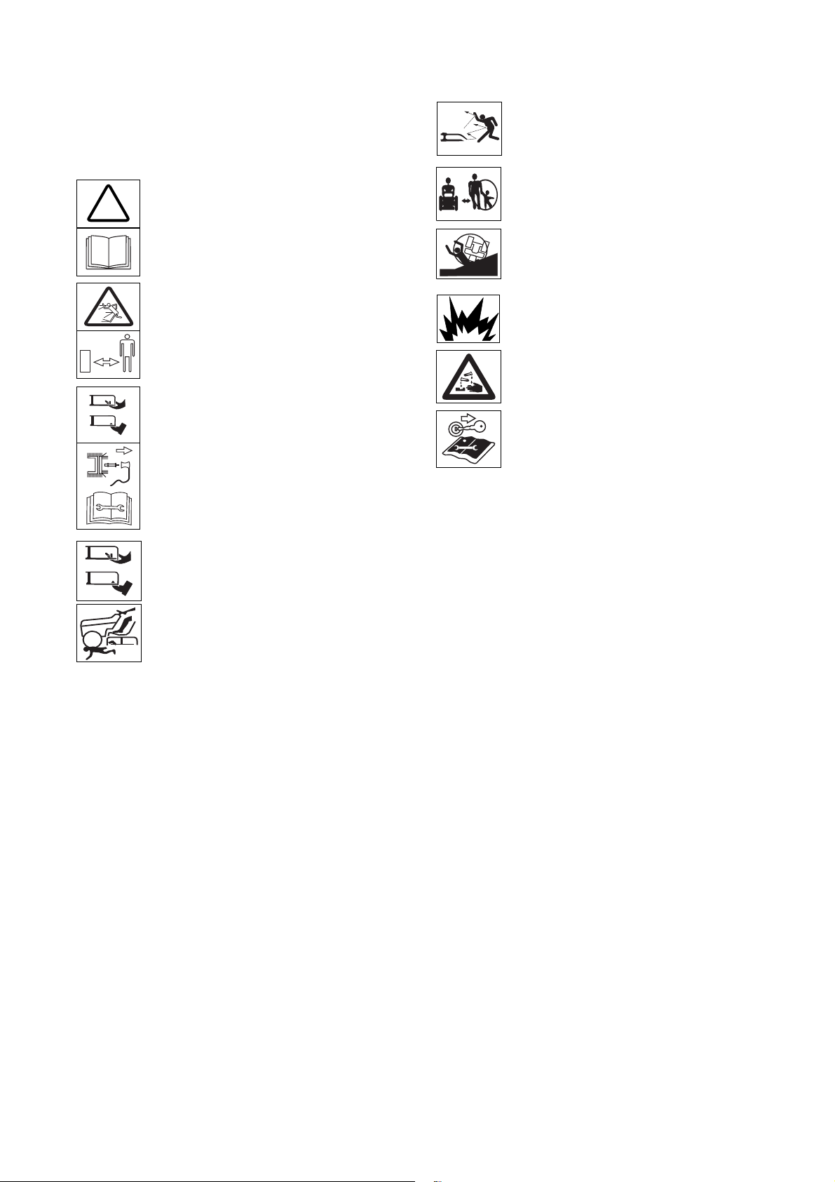
Symbols on the appliance
On the appliance you will find various symbols on
adhesive labels. These symbols are explained in the
followin g:
Attention! Please read the operating
!
instructions before putting appliance into
operation!
Injury hazard due to grass or solid
objects thrown out by mower.
Keep people, in particular children, and
animals away from the area in which the
appliance is being used.
Working on steep slopes can be
dangerous.
Keep third parties away from the danger
area!
Before working on the cutting tools,
remove the spark plug connector! Keep
fingers and feet away from the cutting
tools! Switch off the appliance and
remove the spark plug connector before
adjusting, cleaning, or checking it.
Risk of injury from rotating cutting blades
or parts.
Warning!
Danger of explosion.
Battery acid/
risk of burns.
Before beginning any work on this
machine, remove the ignition key and
observe all information contained in this
guide.
Always keep these symbols on the appliance in
a legible state.
9
Page 10
SAFETY LABELS
1.
KNOW THE OPERATING AND SAFETY INSTRUCTIONS IN THE
OPERATORS’S MANUAL AND ON THE TRACTOR
2.
MOVE THROTTLE TO MID POSITION AND DEPRESS BRAKE PEDAL.
3.
TURN KEY TO THE START POSITION.
1.
DISENGAG E P TO AND SET PARKING BRAKE .
2.
MOVE THROTTLE CONTROL TO MID POSITION AND TURN KEY OFF.
•
GO UP AND DOWN SLOPES, NOT ACROSS.
•
AVOID SUDDE N TURNS.
•
DO NOT OPERATE UNIT WHERE IT COULD SLIP OR TIP.
•
IF MACHINE STOPS GOING UPHILL, STOP PTO AND BACK DOWN HILL SLOWLY.
•
DO NOT MOW WHEN CHI LDREN OR OTHERS ARE AROUND.
•
DO NOT ALLOW P ASSENGERS ON THE TRACTOR AT ANY TIME.
•
LOOK DOWN AND BEHIND BEFORE AN D WHILE BACKING.
•
KEEP SAFETY DEVICES [GUARDS, SHIELDS, AND SWITCHES] IN PLACE AND WORKING.
•
REMOVE OBJECTS THAT COULD BE THROWN BY THE BLADES .
•
KNOW LOCATION AND FUNCTION OF ALL CONTROLS.
•
BE SURE THE BLADES AND THE ENGINE ARE STOPPED BEFORE PLACI NG HANDS
OR FEET NEAR BLADES.
•
BEFORE LEAVING OPERATOR’S POSITION, DISENGAGE PTO, ENGAGE BRAKE LOCK,
SHUT OFF ENGINE AND REMOVE KEY.
•
SLOW DOWN FOR TURNS, ROUGH GROUND AND SLOPES TO AVOID UPSET.
•
ON PUBLIC ROADS USE SMV EMBLEM AND HAZARD LIGHTS.
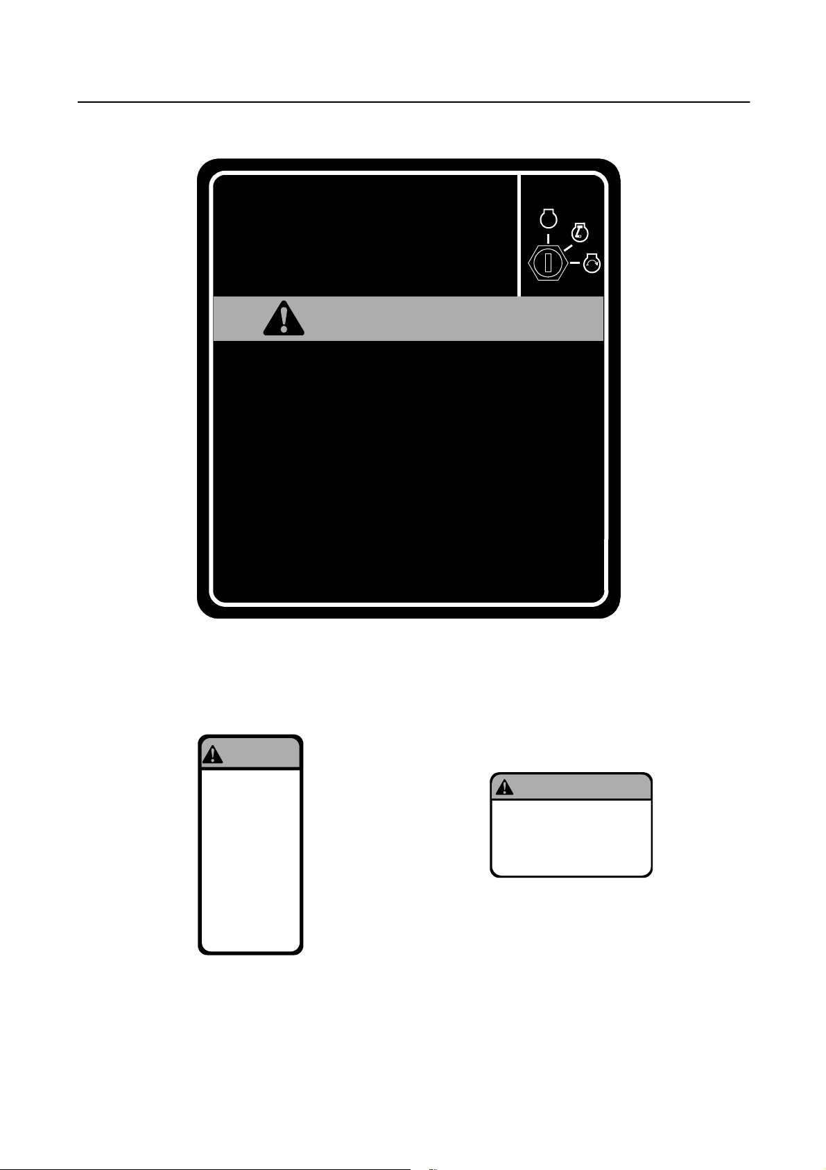
STARTING INSTRUCTIONS
.
STOPPING INSTRUCTIONS
WARN
AVOID SERIOUS INJURY OR DEATH
READ OPERATOR’S MANUAL
I
NG
IGNITION
.
P
O
T
S
INSTRUCTION AND WARNING LABEL
LOCATED ON RUNNING BOARD TUNNEL COVER
WARNING
KEEP HANDS
AND CLOTHING
AWAY FROM
ROTATING FAN
AND BELTS TO
PREVENT
SERIOUS INJURY
FAN WARNING LABEL
LOCATED ON EACH
SIDE OF RADIATOR
WARNING
EXPLOSION AND INJURY CAN
RESULT FROM THE USE OF
STARTING AIDS WITH HOT GLOW
PLUGS, DO NOT I NJECT GASOLINE
OR ETHER IN AIR INTAKE
STARTING AID
WARNING LABEL
LOCATED UNDER HOOD
10
Page 11

SAFETY LABELS (Cont.)
WARNING
To avoid personal injury, keep PTO shield in place.
Pull only from draw bar. pulling from any other point can cause rear overturn.
Disengage PTO and stop engine before servicing tractor, or implements,
or attaching or detaching implements.
FAILURE TO FOLLOW ANY OF THE INSTRUCTIONS ABOVE CAN CAUSE
SERIOUS INJURY TO THE OPERATOR, OR OTHER PERSONS.
LOCATED ON REAR PTO SHIELD
PTO WARNING LABEL
WARNING
BATTERIES CON TAIN ACID AN D EXPLOSIVE GAS.
EX P LO S ION CAN RESULT FROM SPARKS, FLAM ES,
OR W RONG CABLE CONNECTIONS. TO CONNECT
JUM PER CABLES OR CHARGER SEE M ANUAL FOR
CORRECT PROCEDURE. FAILURE TO FOLLOW THE
ABOVE INSTRUCTIONS CAN CAUSE SERIOUS
PERS ON AL INJUR Y OR D EATH .
BATTERY WARNING LABEL
LOCATED UNDER HOOD
WARNING
When improperly operated this tractor can roll over or upset. Use of the ROPS and
sea t be lt mini mize the possibi li ty of inj ury or de at h if roll over or upset occ urs. For
low cl ea ranc e use only, the ROPS c an be lowe red. No pro te ct ion i s provide d in t his
posi tion and t he seat belt should not be fastened . For all ot her use s, secure t he ROPS
in the upright position and fasten the seat belt.
ROLL OVER WARNING LABEL
LOCATED ON RIGHT/REAR FENDER
11
Page 12
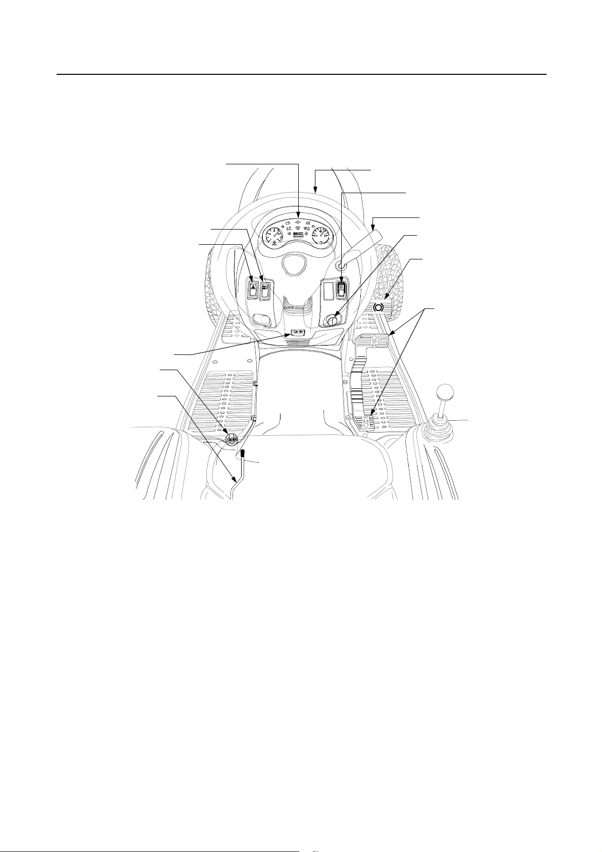
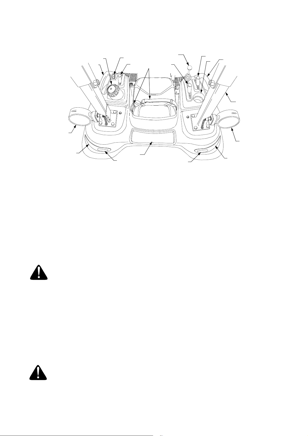
SECTION 1: CONTROLS AND FEATURES
FLOORBOARD AND DASH PANEL MOUNTED CONTROLS
M
L
K
J
H
G
A
B
C
D
E
F
Figure 1
A
Steering Wheel
B
PTO Switch
C
Throttle Handle
D
Ignition Switch
E
Brake Pedal
F
Forward/Reverse Pedal
G
Seat Adjustment Lever
H
Differential Lock Pedal
J
Parking Brake Lever
K
Hazard Light Switch
L
Headlight Switch
M
Instrument Panel
* Steering Wheel and Seat Phantomed For Clarity
12
Page 13
NOTE:
PTO
Switch
Symbol
References to LEFT and RIGHT indicate
that side of the tractor when facing forward while
seated in the drivers seat. Reference to FRONT
indicates the grille end of the tractor; to REAR, the
drawbar end.
A. Steering Wheel
The steering wheel is centered on the dash panel. It
is used to change the d irection (left or right) of the
tractor while driving.
NOTE:
This tractor is equipped with hydraulic
power steering. With this feature, the cap and
spokes of the steering wheel may change position.
B. PTO Switch
Figure 2
The PTO switch is a rocker type switch located to
the right of the steering wheel on the dash panel.
top
Push the
engage the PTO. Push the
of the PTO switch downward to
bottom
of the switch
downward to disengage.
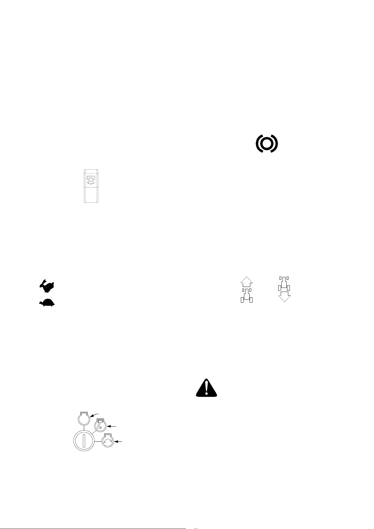
C. Throttle Handle
OFF - The engine and electrical system is turned
off.
ON - The electrical system and glow plugs are
energized.
START- The starter motor will turn the engine.
Release the key immediately when the
engine starts
E. Brake Pedal
Brake Pedal
Symbol
Figure 4
The brake pedal is locate d at the front of the right
floor board. Depress to engage the tractor brakes
and neutralize the hydrostatic transmission. Fully
depress the brake pedal to activate the safety
interlock switch when starting the tractor.
F. Forward/Reverse Pedal
The forward/reverse pedal is a self neutralizing
rocker style peda l loca te d al on g t he righ t flo or b oar d.
Forward Reverse
Pedal Pedal
Symbol Symbol
This symbol indicates the
fast position.
This symbol indicates the
slow position.
The throttle handle is located to the right of the
steering wheel on the dash panel. When set in a
given position, a uniform engine speed will be
maintained. Rotate t he handle rearward t o increas e
the engine speed.
D. Ignition Switch
NOTE:
To prevent accidental starting and/or battery
discharge, remove the key from the ignition swi tch
when the tractor is not in use.
The ignition switch has three positions as follow:
OFF
STOP
ON-PREHEAT
START
Figure 3
Figure 5
Forward
Slowly press down on the front of the pedal to start
moving forward. The forward ground speed of the
tractor is directly affected by the distance th e front
of the pedal is depressed.
Reverse
WARNING:
Check behind the tractor to
be sure the area is clear of people, pets
or obstacles and use a slower speed to
maintain control of the tractor when
traveling in reverse.
Press down on the rear of the pedal to move in
reverse.
G. Seat Adjustment Lever
The seat adjustment lever is located beneath the
left side of the seat. This lev er is used to ad just the
seat forward or backward.
13
Page 14
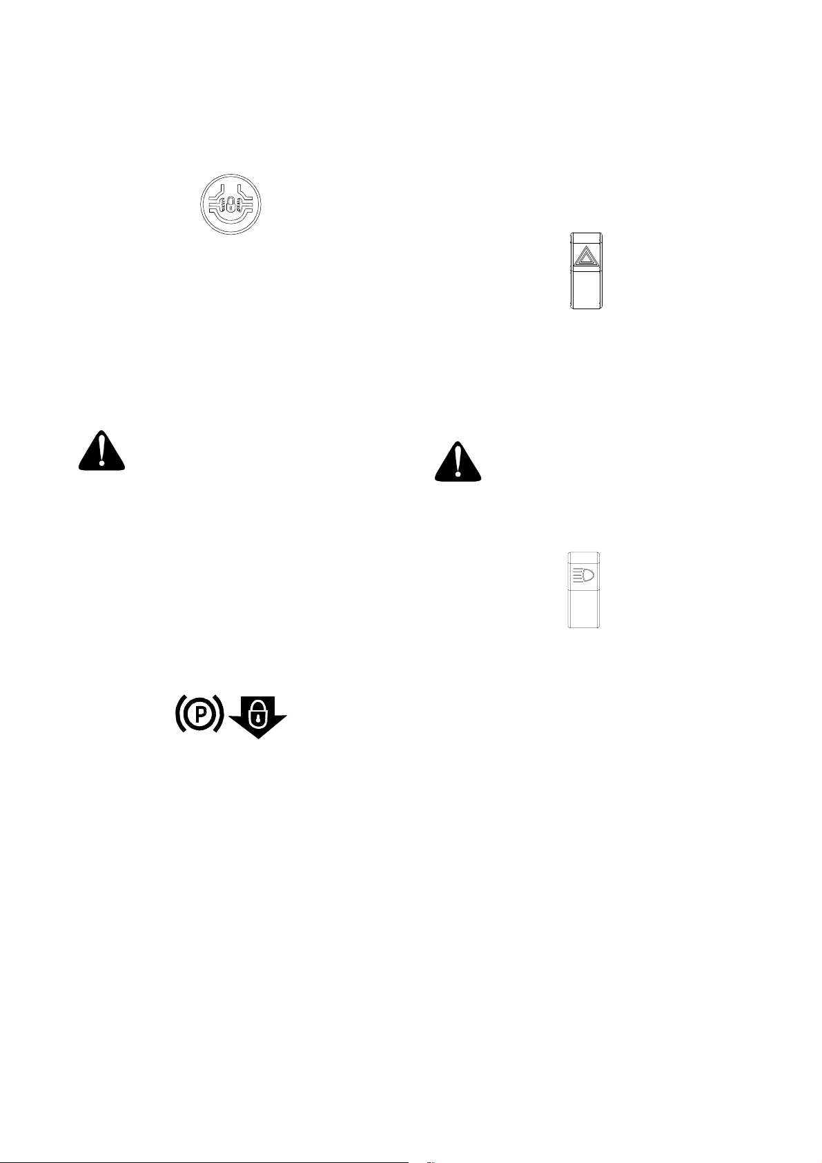
H. Differential Lock Pedal
Diff. Lock
Pedal
Symbol
Figure 6
Located at the rear of the left floor board, the
differential lock pedal engages the transmission
differential lock.
The differential lock is used to gain additional traction when operating th e tracto r on wet o r loose so il.
When the pedal is depressed the rear wheels of the
tractor are prevented from rotatin g inde penden tly o f
one another.
WARNING: When operating with the
differential lock engaged, the tractor
will be difficult to steer. Do not drive
the tractor on roadways or at high
speeds with the differential lock
engaged.
The parking brake lever is located below the
steering wheel in the dash panel. With the brake
pedal fully depresse d, push the park ing brake lev er
downward and release the brake ped al to lock the
parking brake.
K. Hazard Light Switch
Figure 8
The hazard light switch is a rocker type switch
located to the left of the steering wheel on the dash
panel. Push the
top
of the hazard light switch
downward to activate the flashing amber lights.
WARNING: Always activate the flashing hazard lights when operating the
tractor on, or near, roadways.
L. Headlight Switch
NOTE:
Disengagement of the differential lock is
recommended prior to turning the tractor on grass
or other maintained surfaces — tire damage to the
turf could occur.
J. Parking Brake Lever
Parking
Brake
Symbol
Figure 7
Figure 9
The headlight swit ch is a r ocker ty pe s witch loc ated
to the left of the steeri ng wheel on the dash panel.
top
Push the
of the headlight switch downward to
turn on the headlights, in strument panel lights, and
tail lights.
14
Page 15

M. Instrument Panel
7
3
12
10
2
8
6
Figure 10
1. Fuel Gauge
The fuel gauge monitors, at 20 second intervals,
the fuel level in the fu el t ank . The nee dle pointing to
the right indicates a full tank. The ignition switch
must be in the ON position to read the fuel gauge.
2. Tachometer
The tachometer shows the engine speed in r evolutions per minute (RPM). Optimal engine operating
speed is approximately 2500-3600 RPM. When
operating PTO driven atta chments the RPM ind icator needle should b e within the green range on the
tachometer dial.
3. Battery Indicator Light
The bulb illuminates to indicate the battery is be ing
discharged. If this warning lamp comes on during
operation, check the charging system for possible
causes and/or contact your Cub Cadet dealer.
4. Engine Oil Pressure Light
This warning lamp indicates low engine oil pressure. If the bulb comes on while the engine is
running, stop the engi ne immediate ly and check for
possible causes. NOTE:
The bulb may illuminate
when the ignition switch is in the ON position, but
should turn off when the engine is started
.
5. Engine Coolant Temperature Light
Illumination of this warning lamp indicates the
engine coolant temperature has risen above the
prescribed operating range. If the light comes on
while operating the tractor, eliminate all loads and
try cooling the engine by r unning at mid throttle for
a few minutes. Stop the engine and allow to cool;
then check for possible causes (e.g. low coolant
level, plugged radiato r scr een ).
6. Parking Brake Indicator Light
The bulb illuminates when the ignition switch is in
the ON position and the br ake pedal is depressed.
The light flashes if attempting to start the tractor
with the brake not engaged.
4
11
9
5
10
1
7. PTO Indicator Light
Light comes on in a fi xed mode wh enever th e PTO
switch is in the ON position, with the following
exceptions.
• The light will illuminate in a flashing mode if
attempting to start the tractor with the PTO
switch in the ON position.
• The light will chan ge to the flas hing mod e when
the PTO switch is on, but the r everse pedal has
been engaged and the reverse override has
NOT been engaged.
8. Hour Meter
The hour meter records th e hours and tenths of an
hour (
right
most digit) that the tractor has been
operated. The hourmeter is ac tiv ate d wh enev er th e
tractor engine is running. Keep a record of the
hours of operation and maintenance performed to
ensure all maintenance procedures are completed
according to the schedule in this manual.
9. PTO Reverse Override Indicator
This warning lamp illuminates to indicate the PTO
reverse override switch has been depressed and
the PTO reverse override is engaged. Use extra
caution when operating PTO driven attachments
while traveling in the reverse direction.
10. Hazard Light Indicator
Arrows will flash in conjunction with the amber hazard
lights when the hazard light switch is tu rned on.
11. Glow Plug Indicator Light
Illuminates when the ign ition switch is turne d to the
ON position. The li ght remains lit for a pres et time
while the glow plugs heat the precombustion
chambers of the diesel engine.
12. Cruise Control Indicator Light (Optional)
15
Page 16
FENDER MOUNTED CONRTOLS AND FEATURES
A
G
H
J
B
C
K
N
L
O
D
K
E
G
F
M
H
J
Figure 11
A
Fuel Fill Cap
B
PTO Reverse Override Switch
C
PTO Selection Lever
D
Hydraulic Lift Lever
E
Trans. Hi/Lo Shift Lever
F
Cup Holder
G
Hand Holds
H
Amber Hazard Lights
J
Tail Lights (Red)
K
Reverse Lights (White)
L
Storage Tr ay
M
Foldable ROPS
N
Seat Belt
Auxiliary Hydraulic Control HandleO
A. Fuel Fill Cap
The fuel fill cap is located on the left fender beside
the operator’s seat.
WARNING: Never fill the fuel tank to
the top of the filler neck. Expansion
could result in overflow, allowing
highly flammable fuel to come in
contact with the operator.
B. PTO Reverse Override Switch
The PTO reverse ove rride switch is located on the
left fender. Depress the front of the switch to
engage the override which allows the PTO to
operate while the tractor is traveling in the reverse
direction.
Once activated, this function remains
activated until the ignition switch is turned to
the OFF position,
regardless of the number of
times the PTO is turned off using the PTO switch.
WARNING: Use EXTREME caution
when operating PTO driven attachments while traveling in the reverse
direction.
C. PTO Selection Lever
The PTO selection lever is located on the left
fender.
• Push the lever forward to engage the mid PTO.
• Push the lever rearward to engage the rear
PTO.
• Move the lever to the center position to
simultaneously eng age both the rear PTO and
mid PTO.
D. Hydraulic Lift Lever w/Position Control
The hydraulic lift lever is located on the right fender.
This lever controls the position of the three point
hitch lift arms. There is a direct relationship
between the position of the lever and the height
position of the installed equipment.
• To lower the lift arms, move the lift lever
forward until the desired height setting is
attained.
• To raise the lift arms, move the lift lever
rearward until the desired height setting is
attained.
16
Page 17

E. Transmission Hi/Lo Range Shift Lever
The Hi/Lo range shift lever is located on the right
fender. The lever has two spe ed ran ge settings and
a neutral position. The lever must be shifted into
either the high or low range p rior to depressing the
forward/reverse pedal to drive the tractor .
• Push the lever forward to shift into the high
range.
• Push the lever rearward to shift into the low
range.
• Move the lever to the center position to shift
into the neutral position.
WARNING: Never attempt to shift the
range lever when the tractor is in
motion.
F. Cup Holder
The cup holder is located on the right fender.
G. Hand Holds
Hand holds are built into both the left and right hand
fender covers. The han dle s can be used to assist in
mounting and dismounting the tractor.
H. Amber Hazard Lights
The hazard lights are located on each side of the
ROPS bar. The lights illumin ate in a flashing mode
when the hazard light switch is turned on. Always
use the hazard lights when it is necessa ry to warn
others that the tractor is being operated in the area.
J. Tail Lights
The tail lights illuminate wh en the ignition switch is
in the ON position and the headlight switch is
turned on.
K. Reverse Lights
The reverse lights illuminate when the tractor is
being operated in the reverse direction.
L. S tor age Tray
The storage tray is located behind the seat. Us e th e
tray to carry small loose artic les while ope rating th e
tractor.
M. Foldable ROPS (Rollover Protective Structure)
ROPS is installed to prevent or reduce injuries to
the operator should the tractor accidentally overturn. The foldable feature allows the ROPS to be
lowered when operating in areas with low overhead clearance. The protection provided by the
ROPS is minimized if the se at belt is not used and
eliminated when in the folded position.
N. Seat Belt
The seat belt, properly adjusted and used in
conjunction with the Rollover Protective Structure
(ROPS), can greatly reduce the risk of serious
injury or death to the operator if an accidental
tractor overturn occurs.
WARNING: DO NOT use the seat belt if
the ROPS is in the folded position, or
the structure has been removed from
the tractor.
O. Auxiliary Hydraulic Control Handle
The auxiliary hydraul ic control handle is lo cated on
the front of the right hand fender cover. Use this
handle to control the movement of attachments
connected to the auxiliary hydraulic system of the
tractor.
17
Page 18

SECTION 2: OPERATION
ROLLOVER PROTECTIVE STRUCTURE (ROPS)
This tractor is equipped with a foldable Rollover
Protection Structure (R OPS) and seat belts. When
used together they a re effective i n reducing i njuries
to the operator in the eve nt of an accidental tractor
rollover. The safety provided by the ROPS is
minimized if the seat belt is not properly adjusted
AND buckled. Refer to ADJUSTMENTS for seat
belt adjustment.
ROPS
FOLDING THE ROPS
The foldable ROPS feature allows the operator to
quickly lower the ROPS to ope rate in areas where
there is low overhead clearance. However, the
ROPS should be used in the lowered position only
when absolutely necessary. Operate with the
ROPS in the ‘up’ position whenever possible.
WARNING: A folded ROPS does not
provide rollover protection. When the
ROPS is in the folded position, the seat
belt must NOT be used.
Reposition the ROPS as follows:
• Slightly lo osen the two hex scre ws on the front
of the ROPS to relieve their pressure on the
ROPS. See Figure 13.
• Remove the tw o internal cotter pins, and, whil e
supporting the ROP S, withdraw the c levis pins.
See Figure 13. Carefully lower the ROPS.
• Reinstall the clevis pins and cotter pins for
storage.
Figure 12
WARNING: Always wear the seat belt
when operating the tractor equipped
with a ROPS. However, if the ROPS is in
the folded position or has been removed, the seat belt must not be used.
Use the following guidelines when using a tractor
equipped with a ROPS:
• Be aware of o ve rh ead cle ar ances in the area of
operation. Check for cl ear an ce of doo r (or ga te)
openings and other overhead objects such as
utility lines and tree branches. Overhead
objects could catch the ROPS and upset the
tractor.
• Do not modify th e RO PS b y dril li ng ho le s for , or
welding accessories to the structure.
• Do not use the ROPS to pull objects with the
tractor. Use ONLY the tractor drawbar for
pulling.
• In the event of an accident, have the ROPS
carefully inspec ted and, if necessary, replaced
by your
Cub Cadet
dealer. Do not attempt to
repair the ROPS.
CLEVIS
PIN
INTERNAL
COTTER PIN
HEX
SCREW
CLEVIS
PIN
Figure 13
To raise the ROPS:
• Remove inter nal cotter pin s and clev is pins an d
lift the ROPS into position.
• Insert the clevis pins and secure with the
internal cotter pins.
• Tighten the hex screws against the ROPS.
18
Page 19

SAFETY INTERLOCK SYSTEM
• Do not smoke while refueling the tractor.
This tractor is equipped with a safety interlock
system for the protection of the operator. If the
interlock system should ever malfunction, do not
operate the tractor. Contact your authorized
Dealer. The safety i nterlock syst em prevents
Cadet
the engine from cranking or starting unless the
brake pedal is fully depressed, and the PTO is
“OFF”.
• The safety interlock system will shut off the
engine if the operator leaves the seat before
engaging the parking brake.
• The safety interlock system will shut off the
engine if the ope rator leaves the seat with the
PTO “ON”, regardless of whether the brake
lock is engaged.
NOTE:
The PTO switch must be moved to the
Cub
“OFF” position to restart the engine. If the
reverse override fu nction had bee n activated, it
will remain activated until the ignition switch is
turned to the "OFF" position.
• The safety interlock system will shut off the
PTO if the
unless the reverse override function is
activated.
FUELING THE TRACTOR
Fill the fuel tank with only clean, fre sh, diesel fuel.
Fuel with a cetane number of 45 is recommended,
but fuel with a minimum cetane number of 40 is
acceptable. To ensure the freshness of the fuel,
purchase fuel in a quantity tha t can be used within
30 days.
NOTE:
DO NOT USE KEROSENE OR GASOLINE
reverse control pe dal
is depressed,
in your diesel engine. Damage to the engine will
occur.
Generally a good grade Number Two Diesel Fuel
should be used in your diesel en gine. However, in
extremely cold temp eratures a qualit y Number One
Diesel Fuel, or a blend of Number O ne an d Num ber
Two Diesel fuels should be used. In most areas,
diesel fuel is prop erly blended for seasonal use as
ambient temperatures change. Therefore, it is
important to monitor fuel purchases so that
seasonal grade fuels are not carried over after the
average ambient temperature has changed.
WARNING: Never fill the fuel tank to
the top of the filler neck. Expansion
could result in overflow through the
vents in the cap, allowing fuel to come
in contact with the operator.
• Do not fill the fuel tank when the engine is
running or while the engine is hot.
• The fuel fill c ap is located on the fen der to the
left of the seat. Unscrew the fuel cap and fill
tank from an approve d container. Do not fill the
fuel tank to capacity. Allow room for expansion.
• Tighten the fuel c ap securely, and immediately
wipe up any spilled fuel.
• To minimize condensation, keep the fuel tank
as full as possibl e wi tho ut fi ll in g to ca pac ity . I t is
a good practice to fill the f uel tank at the en d of
the day to reduce overnight condensation.
• Do not allow the fu el tank to run dry. Running
out of fuel requires bleeding air and repriming
the fuel system.
WARNING: Fuel in the engine injection
system is under high pressure. If not a
qualified mechanic, do not attempt to
service the fuel injection system. Do
not use your hand to check for leaks.
NEW TRACTOR BREAK-IN PROCEDURES
Proper care during the first hours of operation will
help to assure optimal performance from your ne w
tractor.
• Never operate a new engin e imm ediately under
full load. Allow the engine to warm up.
• Avoid operating the engine for prolonged
periods at either high or low speeds with no
load.
• Use the transmission’s low speed range for
heavy loads to avoid lu gging of the engine due
to overload.
• Closely monitor the engine oil and coolant
levels, and keep filled to the recommended
levels.
• After the first ten hours of operation, check all
of the front and rear wheel bolts. If necessary ,
retighten to the following torque:
Front Wheels — 74 Nm
Rear Wheels — 108 Nm
• Perform all break-in maintenance procedures
found in the MAINTENANCE section.
19
Page 20

STARTING THE ENGINE
WARNING: Always sit in the operator’s
seat when starting the tractor, Never
attempt to start the engine while
standing beside the tractor.
• Observe the instrument panel. If the battery
indicator light, oil pressure light, or coolant
temperature light comes on, immediately stop
the engine. Have the tractor inspected b y your
Cub Cadet
dealer.
WARNING: Never use starting fluids,
such as ether, as a start ing aid. Severe
engine damage or fire could result.
• Check the engine oil and coolant levels.
• Operator must be sitting in the tractor seat.
• Move the throttle handle to the full (FAST)
throttle position. Refer to Figure 14.
• Make sure the PTO switch is in the “OFF”
position.
Note: The PTO light on instrument
panel will flash if switch is in ON position.
THROTTLE
HANDLE
SLOW
FAST
PTO SWITCH
IN ‘OFF’
POSITION
Figure 14
• Either fully de press and ho ld the brake ped al or
engage the parking brake.
Note: The parking
brake indicator o n instrument panel will flash if
pedal is not depressed
.
• Turn the ignition key clockwise to the "RUNPREHEAT" position, an d obse rve the gl ow plu g
indicator light on the instrument panel. Wait
until the glow plug indicator light turns off
before cranking the engine.
NOTE:
engine has been running and is warm
Preheating may not be necess ary if the
.
• Turn the ignition key to the “START” position
and release it as soon as the engine starts;
however, do not crank the engi ne continuously
for more than 20 seconds at a time. If the
engine does not start w ithin this time, turn the
key to “OFF” and wait at least one minute to
allow the engine’s starter motor to cool. Try
again after waiting.
• After the engine has started, slowly move the
throttle lever to the idle position. Allow the
engine to idle for approximately three to five
minutes before putting the engine under load.
COLD WEATHER STARTING
Ensure that the correct viscosity grade of lubricating
oil is used for the ambient temperature range in
which the engine will run, as shown in the
lubrication table in the MAINTENANCE section of
this manual. Place the th rottle co ntrol in the low idl e
(SLOW) position if the temperature is below 32°F
(0°C), then follow the normal engine starting
instructions above. Allow the eng ine additional time
to warm up.
USING JUMPER CABLES TO START ENGINE
WARNING: Batteries contain sulfuric
acid and produce explosive gasses.
Make certain the area is well ventilated,
wear gloves and eye protection, and
avoid sparks or flames near the battery.
If the battery loses power and is unable to
adequately crank the engin e to start it, the aid of a
booster battery may be necessary. Connect the
booster battery as follows:
• Connect the ends of one jumper cable to the
positive terminals of both the disabled tractor
battery and the booster battery.
• Connect one end of the other cable to the
booster battery’s negative terminal.
• Connect the other end of that cable to the
engine block or frame of the disabled tractor, as
far from the battery as possible.
• Start the disabled tractor following the normal
starting instructions previously provided; then
disconnect the jumper cables in the exact
reverse order of connection.
• Have the tractor’s electrical system checked
and repaired as soon as possible to eliminate
the need for jump starting.
STOPPING THE ENGINE
• Place the PTO switch in the “OFF” position.
• Place the throttle control as follows:
- If the engine has been operated at low loads ,
place the throttle control lever in the “SLOW”
position and allow th e engi ne to i dle for about
one minute.
- If the engine has been operate d at high l oad,
run the engine at approximately 1/2 throttle
for three to five minutes to reduce the en gine
coolant and oil temperatu res. Then move the
throttle control to the "SLOW" position.
20
Page 21

• Turn the ignitio n key to the “OFF” position an d
remove the key from the ignition switch.
NOTE:
Always remove the ke y fro m th e ig ni tio n
switch to prevent accidental starting or battery
discharge if the equipment is left unattended.
DRIVING THE TRACTOR
WARNING: Avoid sudden starts, excessive speed and sudden stops.
Do not leave the seat of the tractor
without disengaging the PTO and
engaging the parking brake. If leaving
the tractor unattended, turn the ignition key off and remove key.
• Adjust the operator ’s seat to the most comfortable position that allows you to operate all
controls and pedal s. See seat adjustment in th e
ADJUSTMENTS section.
WARNING: DO NOT use the seat belt if
the ROPS is in the folded position or
has been removed from the tractor.
• Adjust the se at bel t to fit s nugly but c omfortab ly
around your lap, then buckle the seat belt.
Refer to ADJUSTMENTS section.
• Shift the transmi ssion Hi/ Lo range sh ift lever on
the right fender to the desired speed setting.
Refer to USING THE HI/LO RANGE SHIFT
LEVER in paragraphs below.
• Use the trac tor and /or the auxiliary hydrauli c lift
lever(s) to raise all tractor attachments from the
ground if transporting the tractor to a work site.
• Depress the brake pedal to release the parking
brake, then slowly release the brake pedal.
• Move the throttle handle to the position where
the engine operates best for the load to be
handled (normally full throttle).
• Slowly depress either the front or rear of the
forward/rever se pedal to move t he tractor in the
desired direction. Refer to USING THE
FORWARD/REVERSE PEDAL.
DRIVING ON SLOPES
WARNING: Do not operate on inclines
with a slope in excess of 15 degrees
(a rise of approximately 25 cm every
1 Meter). The tractor could overturn
and cause serious injury.
IMPORTANT:
Always shift the transmission
into the LOW speed range BEFORE beginning
the climb or descent of any slop
Operate the tractor up and down slopes, never
across slopes. Do not drive so that the tractor may
tip over sideways.
e.
Before operating the tractor on a slope, walk the
slope to look for possible hazards such as rocks,
mounds, stumps, or surface irregularities which
could cause the tractor to be upset.
Back the tractor with attachment up the steepest
portion of each slope you intend to work. If the
tractor cannot negotiate the slope in reverse, the
slope is too steep to be worked.
Avoid turns when drivin g on a slope. If a turn must
be made, turn down the slo pe. Turning up a slope
greatly increases the chance of a roll over.
Avoid stopping when driving up a slope. If it is
necessary to stop while drivin g up a slope, start up
smoothly and carefully to reduce the possibility of
flipping the tractor over backward.
STOPPING THE TRACTOR
• Fully depress the brake pedal to bring the tra ctor to a complete stop. Push downward on the
parking brake lever and release the pedal to
engage the parking brake. Refer to Figure 15.
• Disengage the PTO using the PTO switch.
• Place the throttle control lever in the “SLOW”
position and allow the engine to idle for about
one minute; then turn the ignition switch to
“OFF’” and remove the key from the switch.
• Depress the center button of the seat belt buckle
to release the seat belt before dismounting.
USING THE FORWARD/REVERSE PEDAL
The hydrostatic transmission provides constantly
variable ground speeds within the speed rating of
each transmission range. The tractor speed is
controlled by the forward/reverse rocker pedal on
the
right
floorboard.
The forward/reverse pedal i s self neutralizing. The
transmission and pedal return to neutral and the
tractor stops when the pedal is released.
• To move forward, slowly depress the front of
the forward/reverse pedal until the desired
speed is achieved. The speed of the tractor is
directly related to the distance the pedal is
depressed. Refer to Figure 15.
• To move in rever se, check that the area be hind
is clear then slowly depress the rear of the
forward/reverse peda l.
• When traveling short distances with frequent
changes in direction, th e fo rwa rd /rev erse ro cker
pedal may be operated using the heel/toe
method. Place your foot on the center section
of the pedal and press downward with your
toes to move forward. Press downward with
your heel to move in reverse.
NOTE:
Slightly more effort is needed to depress the
forward/reverse pedal using the heel/toe method.
21
Page 22

BRAKE PEDAL
FORWARD/
REVERSE
PEDAL
Forward
PARKING
BRAKE
LEVER
Heel/Toe
Operation
Reverse
Figure 15
WARNING: The forward/reverse pedal
will not operate when the parking brake
is engaged. Do not attempt to force the
pedal when the parking brake is
engaged; this could cause premature
wear or damage to the drive linkage.
LOW range — Shift the lever fully rearward in slot.
Forward speed 0 to 10.2 km/h.
Reverse speed 0 to 5.1 km/h.
Low range is recomme nded for use with most PTO
driven tractor attachments. Low range must be
used when climbing or descending slopes.
NEUTRAL — Shift the lever to the center of slot.
Disengages the transmission drive.
Use ONLY for towing or moving the tractor when
not under power.
USING THE DIFFERENTIAL LOCK PEDAL
Depressing the differential lock pedal engages a
mechanism in the transmission that locks the
differential. This prevents the rear wheels from
rotating independently of each other and provides
constant power to bot h rea r wheels when a dditional
traction is needed.
IMPORTANT:
Do not engage the differential
lock when one of the rear wheels is rotating.
Stop the wheel rotation and then engage the
differential lock.
USING THE HI/LO RANGE SHIFT LEVER
WARNING: The tractor must be
stopped before engaging or disengaging the transmission Hi/Lo range shift
lever. Shifting while the tractor is in
motion will cause damage to the
transmission.
WARNING: Always maintain a tractor
speed that allows for complete control
and stability of the machine. Be awar e
of dangerous areas or conditions.
Push the lever to the righ t side of the slot to clear
the shift gate, then shift the lever as follows:
HI range — Shift the lever fully forward in slot. Se e
Figure 16.
Forward speed 0 to 17.7 km/h.
Reverse speed 0 to 8.8 km/h.
Hi range is normal ly used for transport and can be
used with some tractor attachments
LOW
HI
N
HI/LO RANGE
LEVER
SHIFT
WARNING: When operating with the differential lock engaged, the tractor will
be difficult to steer. Do not drive the
tractor on roadways or at high speeds
with the differential lock engaged.
• Fully depress and hold the differential lock
pedal to engage the transmission differential
lock. Release the pedal to disengage the
differential lock. See Figure 17.
DIFFERENTIAL
LOCK PEDAL
(Depress and
Hold to Engage)
SHIFT GATE
Figure 16
Figure 17
NOTE:
Because of the drive load on the internal
engagement mechanism, releasing the differential
lock pedal may not always disengage the
differential lock. It may be necessary to slow the
tractor, or reverse the direction of travel, to
disengage the differential lock.
22
Page 23

USING THE HYDRAULIC LIFT LEVER
The hydraulic lift sy stem provides power for raising
and positioning three point hitch and belly mounted
equipment. The system’s position control feature
maintains the selected height or depth of the
equipment. When the hy draul ic li ft lev er is mov ed to
a higher or lower s et tin g, t he sy s tem r epo si tio ns the
equipment and maintains that selected position.
• To raise an attachment using the hydraulic lift
system, the engine must be running.
• Generally, an attachment can be lowered with
the engine running or off.
• There is a direct relationship between the
height of the equi pment and the positio n of the
lever in its slot. Operate the equipment to
determine your preferred height setting and,
consequently, the positio n of the lift lever in its
slot.
• Move the lift lever forward in the slot to the
position that lowers the equipment to the
desired height setting. See Figure 18.
HYDRAULIC
LIFT LEVER
Lowest
Height
Position
Highest
Height
Position
Figure 18
• Move the lift lever rearward in the slot to raise
the equipment to a h igher height setting, or all
the way rearward to raise the equipment to the
transport position. See Figure 18.
USING THE PTO SELECTION LEVER
WARNING: NEVER shift the PTO selection lever while the PTO is engaged.
Damage to internal components will
occur.
The position of the PTO selection lever will determine whether the rear PTO, mid PTO, or both
PTO’s will be engaged when the PTO switch is activated.
Pull the lever to the rig ht side of the s lot to cl ear the
shift gate, then shift the lever as follows:
• Shift the PTO selection le ver rearward to select
the rear PTO. The rear PTO is used to drive
equipment designed to operate at an input
speed of 540 RPM. See Figure 19.
PTO REVERSE
OVERRIDE
SWITCH
SHIFT GATE
Rear
PTO
PTO
SELECTION
LEVER
Mid &
Rear
PTO
Mid
PTO
Figure 19
• Shift the PTO lever forward to select the mid
PTO. The mid PTO is used to drive equipment
designed to operate at an input speed of 2000
RPM. Refer to Figure 19.
• Shift the PTO lever to the middle position to
select both the mid PTO and rear PTO. The
mid PTO and rear PTO will run simultane ously
when the PTO switch is activated. Refer to
Figure 19.
NOTE:
Occasionally you may not be able to shift
from one PTO selecti on to another due to a slight
misalignment between the internal shift collar and
the gears. In these in stances if will be necessar y to
‘jog’ the PTO while shifting the selection lever.
Momentarily engage the PTO while applying light
pressure on the shift lever to fully engage the
internal gears.
ENGAGING THE P TO
WARNING: The operator must be in the
seat at all times when the PTO in
engaged. If the operator should leave
the seat without turning off the PTO
switch, the tractor’s engine will shut
off.
• Move the throttle handle to the mid throttle
position. Refer to Figure 20.
top
• Push the
of the PTO switch downward to
engage the PTO (Refe r to Figure 20). The PTO
light on the instrument panel will come on.
• Move the throttl e handle to the fu ll throttl e position. When operating PTO driven attachments,
observe the tachometer on the instrument
panel to ensure the RPM indicator needle is
within the green range on the tachometer dial.
23
Page 24

THROTTLE HANDLE
Mid Thro ttle
to Engage
3500 RPM
to Run
PTO SWITCH
Figure 20
• Push the
bottom
of the switch downward to
disengage the PTO.
IMPORTANT:
Normally the PTO will not
operate when the tractor is dri ven in th e rev ers e
direction. The PTO reverse override switch
must be activated to operate the PTO while
traveling in reverse.
USING THE PTO REVERSE OVERRIDE SWITCH
The PTO reverse override switch, located on the
left
fender, allows the PTO to operate while the
tractor is traveling i n the reverse direction. Refer to
Figure 19.
• The PTO must firs t be engaged using the PTO
switch on the dash panel.
• Depress the front of the override switch to
activate the reverse override system. The light
in the instrument panel will come on.
IMPORTANT:
Once activated, the reverse
override will remain activated until the ignition
switch is turned to the OFF position, regardless
of the number of times the PTO is engaged and
disengaged using the PTO switch. If the
override switch is illuminated, the system is
activated.
WARNING: Use EXTREME CAUTION
when operating PTO driven attachments while traveling in the reverse
direction.
LIGHTING
Headlights and Taillights
Always use the headlights and taillights for after
dusk and pre-dawn operation of the tractor. The
lights not only illuminate the work area, but also
increase the visib ility of the tractor for anyone who
might enter the area of operation.
The headlights use two halo gen bul bs per si de. The
placement of the bulbs prov ide a broad light range
for safer operation of the tractor in low light
conditions.
• To turn on the headl ights and tai llights, depre ss
the top end of the headlight switch located to
the left of the steering wheel.
• To turn off the headl ights and tai llights, depre ss
the bottom of the light switch.
Use of headlights and taillights is also recommended when operating the tractor on or near roadways to increase visibility to traffic.
Hazard Lights
Always use the flashing a mber hazard lights along
with the SMV (Slow Moving Vehicle) emblem when
operating the tractor on, or near, roadways. Also
activate the haza rd lights when necessary to w arn
others that the tractor is being operated in the area.
• To turn on the flashing hazard lights, depress
the top end of th e haz ard li ght s witch loc ated t o
the left of the headlight switch.
• To turn off the hazard lights, depress the
bottom of the light switch.
USING THE TOP LINK RETAINER HOOK
The top link hook i s provided to retain the the top
link of the three point hitch when not in use.
To utilize the top link hook, proceed as follows:
• While holding the top link upward, raise the
hook rod and slide it fully to the
locks in the u pright position in the
left
so that it
right
slot of
the mounting bracket.
• Lower the top link into the hook of the rod.
• To release the top li nk, lift the to p link out of the
retainer hook; then slide the hook rod fully to
right
the
MTG. BRACKET
HOOK ROD
LOCKED IN
BRKT. SLOT
and pivot it downward.
TOP LINK
HOOK ROD
RELEASED
Figure 21
24
Page 25

USING THE THREE POINT HITCH
WARNING: Always disengage the PTO,
stop the engine, and set the parking
brake before dismounting the tractor
to connect, disconnect, or adjust three
point hitch mounted implements.
Use the rear three point hitch system to attach
three point mounted implements, which are
normally driven by the rear PTO. Us ing the pos ition
control feature of th e tractor’s hydraulic lift s ystem,
the three point hitch system provides for variable
positioning of the implemen t as well as allo wing the
implement to be fully raised for transport.
Read the ADJUSTMENTS section for instructions
on adjusting the RH a djustable lift link, upp er hitch
link, and hitch chain. See Figure 22.
USING THE AUXILIARY HYDRAULIC VALVE
Some tractors may be equipped with an auxiliary
hydraulic valve package. This package provides
two hydraulic circuits for operating optional
equipment that can be installed on the tractor.
The male and female hydraulic couplers, located
beneath the right running board, are marked with
color coded washers that should match the color
coded hydraulic lines of
Cub Cadet
equipment. See
Figure 23.
IMPORTANT: If color coding is not present, note
that the inner hydraulic couplers represent one
hydraulic circuit and the outer couplers the
other. Do not cross connect circuits when
connecting hydraulic lines of optional
equipment.
UPPER
HITCH LINK
FIXED
LIFT
LINK
HITCH
PLATE
LOWER HITCH LINK
DRAW
BAR
ADJUSTABLE
LIFT LINK
HITCH
CHAIN
Figure 22
USING THE HITCH PLATE
Use only the hitch plate and drawba r (Refer to Figure 22), for towing pull-behind equipment (carts,
trailers, etc.) or dragging loads.
Raise the lower links of t he three poin t hitch to the ir
highest position to prevent interference with the
towed equipment.
IMPORTANT:
When transporting pull-behind
equipment, always use a safety chain to supplement the connection between the tractor and
towed equipment. The safety chain must have
a strength rating equal to or greater than the
gross weight of the equipment being towed.
OUTER
FEMALE
COUPLER
INNER
OUTER
MALE
COUPLER
COUPLERS
Figure 23
Using the Auxiliary Hydraulic Control Handle
Use the auxiliary hydraulic control handle located
on the right fender as follows:
• Pull the handle rearward to raise the front
hitch or front loader boom. See Figure 24.
• Push the handle forward to lower front hitch
or front loader boom. Refer to Figure 24.
• Push the handle fully forwa rd until it locks in
the detent positio n to place the front hitch or
front loader boom in the float position.
• Push the handle to the right to angle (if
equipped) the front hi tch to the r igh t o r dum p
the loader bucket. Refer to Figure 24.
• Pull the handle to the left to angle (if
equipped) the front hitch to the left or roll
back the loader bucket.
25
Page 26

FLOAT HITCH
FLOAT BOOM
LOWER HITCH
LOWER BOOM
ANGLE LEFT
ROLLBACK
BUCKET
RH FENDER
COVER
ANGLE RIGHT
DUMP BUCKET
RAISE HITCH
RAISE BOOM
Figure 24
“ON DEMAND” FOUR WHEEL DRIVE
The “On Demand” Four Wheel Drive system
automatically delivers power to the front axle
whenever the need for add itional traction is sen sed
by the transmissi on. No action from the operator is
required for engagement.
TRACTOR WEIGHTING
When implements are installed on either the front or
rear of the tractor, the normal balance of the tr actor
is altered.
• As a rear mounted implement is raised to the
transport position, the balance point of the
tractor shifts rearward, which may result in a
loss of steering control and tractor stability.
• When a front mounted imple ment is raised, the
balance point shif ts forwar d and may r esult in a
loss of traction and stability.
To counterbalance these weight shifts, weight
should be added to the tracto r in the form of either
cast iron weights or liquid ballast. However, only
enough weight should be added to obtain good
traction, control, and stability. Exces sive weight will
unnecessarily load down the tractor’s engine and
transmission.
NOTE:
When adding weight to the tractor, it may be
necessary to increase the inflation pressure in the
tires.
Front Weights
To counterbalance three point hitch mounted
equipment, a weight bracket/bumper kit and cast
iron weights are available from your
Cub Cadet
dealer.
When mounting optional
Cub Cadet
equipment on
the rear of the tractor, such as a rotary tiller, rotary
cutting deck, or a rear finish mower, the weight
bracket and a minimum of four suitcase weights
should be used.
For all other rear mounted equipment, follow the
guidelines provided in the implement’s Operator’s
Manual to determine ho w much weight is needed to
counterbalance the equipment.
If guidelines are not av ailable, ballast th e tractor so
that a minimum of approximately 40% of the
machine weight is on the front wheels.
Weighting the Rear of the Tractor
Adding weight to the rear of the tractor is not
required for most
Cub Cadet
front mounted
equipment currently available for this tractor.
However, if installing only the optional front end
loader (without the back hoe), weight must be
added to the rear of the tractor. The most common
methods of adding wei ght are fi lling the re ar wheels
with liquid ballast (usually a calcium chloride and
water solution) or mounting a rear weight box.
Liquid Ballast
Properly filling the rear tires with liquid ballast
increases the weight of each rear wheel to
approximately 90 kg, which should provide
adequate counterbalance.
Because special equipment and a familiarity with
the practice is required, only a qualified tire
technician should perform this procedure. Consult
with your
Cub Cadet
dealer about having liquid
ballast added to your tires, and for any special
maintenance instructions after the procedure is
performed.
Rear Weight Box
A weight box will provide adequat e counterbalance
if the following criteria is met:
• The weight box and contents must total a
minimum of 90 kg.
• The weight b ox must be posi tioned a minimu m
of approximately 5.8 cm rearward of the rear
axle, and be carried n o more than 30.4 cm from
the ground.
If the weight box is positioned closer to the rear
axle or carried higher, additional weight must be
added to effectively counterbalance the front
loader.
26
Page 27

SECTION 3: ADJUSTMENTS
ADJUSTING THE SEAT
For the comfort of the operator, a single lever
adjustable seat is provided to set the fore to aft
position of the seat. Adjust the seat to the most
comfortable position that allows you to operate all
controls and pedals.
WARNING: Do not adjust the seat when
the tractor is moving, as this could
cause the operator to lose momentary
control of the tractor and result in an
accident.
• To adjust the seat, pivot the seat adjustment
lever to the left and hold while r epositioni ng the
seat to the desired position.
• After repositi oning th e seat, releas e the lever to
lock the seat in position. Slide the seat either
slightly forward or rearward to assure it is
locked or until engagement of the lock is felt.
See Figure 25.
Adjust the final length of the seat belt using the
adjuster clip, buckle li nk, and u ppe r belt webbing on
right
the
half of the belt.
• To lengthen the belt, hold the ends of the
adjuster clip and tip upward the side of the clip
toward the buckle link. See Figure 26.
• While holding the clip, pull the upper webbing
of the belt through the clip toward the buckle
link. See Figure 26.
• Hold the belt and pull the buc kle link to the
left
to remove the sl ac k in t he upper webbing of the
belt between the adjuster clip and the link.
RELEASE
BUTTON
BUCKLE
LINK
BUCKLE
UPPER
WEBBING
Tip Sides of Clip
Pull Belt to
Lengthen
Pull Belt to
Shorten
ADJUSTER
CLIP
LOWER
WEBBING
Pivot Lever
SEAT
ADJUSTMENT
LEVER
to Left
Figure 25
ADJUSTING THE SEAT BELT
WARNING: Always wear the seat belt
when operating the tractor equipped
with a ROPS. However, if the ROPS
has been removed, the seat belt
should not be used.
NOTE:
If the belt is too long or too short to be properly adjusted using the upper belt webbing, the
adjustment clip should be repositioned. To do so,
firmly grasp the adj ustment clip and pull the lower
webbing though the c lip. Move the clip toward the
anchor point at the seat to shorten the belt, or
toward the buckle link the lengthen the belt.
Figure 26
• To shorten the belt, tip the other side of the clip
upward, pull the free end of the bel t webbing to
right
the
, and pull the buckle link to the
left
to
remove the slack.
THREE POINT HITCH ADJUSTMENTS
level
• Adjust the RH adjustable lift link to
the
lower hitch links . Loosen the jam nut and turn
the adjustment tube as shown in Figure 27 to
shorten or lengthen the lift link. Tig hten the jam
nut against the adjustment tube after adjusting.
Loosen
Jam Nut
Shorten
JAM
NUT
ADJUSTMENT
TUBE
Lengthen
Figure 27
27
Page 28

• The length of the upper hitch link is normally
determined by the design of each implement.
To adjust the upper hitch link , loosen the locking lever and turn the adjustment tube as
shown in Figure 28. After the appropriate length
is attained, tighten the lo cking lever. If correctly
adjusted, the upp er hitch link will be parallel or
nearly parallel to the lower hitch links.
Lengthen
ADJUSTMENT
TUBE
Shorten
LOCKING
LEVER
• Distance ‘A’ should be 0–0.5 cm less than
distance ‘B’ if the toe-in is correct. If it is not,
readjust the toe-in.
A
Figure 28
• The length of the hitch c hains, atta ched to each
lower hitch link, limit the side-to-side movement of the lower li nks. Loos en the jam nu t and
turn the chain’s hex shaft as shown in Figure
29 to adjust the length of the hitch chain.
Tighten the jam nut after adjusting.
Turn Hex Shaft
to Lengthen
Loosen
Jam Nut
Turn Hex Shaft
to Shorten
HEX SHAFT
HEX JAM NUT
Figure 29
ADJUSTING FRONT WHEEL TOE-IN
The front wheel toe-in is set at the factory and
should maintain the proper setting. However, the
toe-in should be checked periodically and
readjusted if necessary.
B
Figure 30
READJUST THE TOE-IN AS FOLLOWS:
NOTE:
The left ball joint and jam nut are left hand
threaded.
• Loosen the jam nuts at both the LH and RH ball
joints. See Figure 31.
• Slide an open-end wrench onto the flat area at
either end of the tie rod and tu rn the tie rod as
follows:
Rearward to shorten the tie rod and decrease
the toe-in. See Figure 31.
Forward to lengthen the tie rod and increase
the toe-in. See Figure 31.
Front of
Tractor
Shorten Rod —
Decrease T oe-in
Lengthen Rod —
Increase Toe-in
CHECK THE TOE-IN AS FOLLOWS:
• Place the tractor on a level surface with the
wheels in the straight ahead position.
• Place an easily visible mark on the center lines
of both front tires at the horizont al center line of
the wheel.
• Measure and record the distance ‘A’ between
the two ma rks. See Figure 30.
• Roll the tractor forward or rearward until the
marks are at the horizontal center line at the
rear of the wheels. Measure and record the
distance ‘B’ between the marks. See Figure 30.
TIE ROD
JAM NUT
LH BALL JOINT
Figure 31
• Readjust the tie r od as necessary to obtain th e
correct toe-in, then ti ghten the jam nu ts against
the ball joints.
28
Page 29

ADJUSTING THE BRAKES
The tractor brakes are adjusted at the factory and
should experience minimal wear if the tractor is
operated normally. However, all brake pads are
subject to wear and at som e p oi nt th e b ra ke li nk ag e
may have to be adjusted.
Check the brake linkage as follows:
• Place the tractor on a level surface.
• Stop the tract or engine a nd engage the park ing
brake.
• From the right/rear side of the tractor, check the
gap between the flange of the brake rod and
the ferrule connected to the t ransmission brake
arm. The gap should b e a minimum of 0.4 cm .
See Figure 32.
• Check the gap of the brak e rod on the l eft side
of the tractor in the same manner.
• If either gap is less than 0.4 cm , the brake rod
should be adjusted.
Adjust the brake linkage as follows:
• Disengage the parking brake.
• Remove the internal cotter pin and disengage
the adjustment ferrule at the front of the brake
rod from the brake link. See Figure 32.
• Turn the adjustment ferrule onto the rod as
needed to shorten the rod and acquire the
0.4 cm minimum gap.
• Reinstall the ferrule and internal cotter pin in
the brake link.
• Engage the parking brake and recheck the
brake rod gaps. Repeat the abo ve procedures
as necessary to obtain the specified minimum
gap.
ADJUSTING HYDRAULIC LIFT FEEDBACK ROD
Correct adjustment of the feedback rod (Refer to
Figure 33) is ins trumental in prop er oper ation of th e
position control hydraulic lift system.
The feedback rod is adjusted at the factory and
should not require further adjustment. Because of
the precise nature of the feedback rod adjust ment,
it is recommended that any adjustment be performed by a qualified mec hanic at your Cub Cadet
dealer.
If a high pitched s queal continues to emit from the
lift valve after repositioning the lift, or the position
control feature is no t functioning proper ly, have the
position control li nkage insp ected by y our loca l Cub
Cadet dealer. Refer to Figure 33.
BRAKE
ARM
FERRULE
BRAKE
PEDAL
RH BRAKE
LINK ASS’Y.
BRAKE ROD
ADJUSTMENT
FERRULE
ROD
FLANGE
0.4 cm minimum gap
w/brake fully engaged
Figure 32
INTERNAL
COTTER PIN
FEEDBACK
LINKS
FEEDBACK
ROD
HYDRAULIC
LIFT VALVE
Figure 33
29
Page 30

SECTION 4: MAINTENANCE
The service life and reliability of any machine
depends upon the care it is given. Proper lubrication and maintenance is a vital part of that care.
Using the
Lubrication and Mai ntenance Chart
as a
guide, monitor the hourmeter on the instrument
panel to ensure the required maintenance procedures are performed. The maintenance schedule
reflects the minimal requirements to maintain the
equipment. More frequent inspections and maintenance is preferable.
Make certain tha t all lubric ation fitting s are inst alled
and functioning. Wipe aw ay all old grease and dirt
from the lube fittings to prevent foreign materials
from entering as the new gr ease is applied. Use a
LUBRICATION TABLE
Application
Type of
Lubricant
Capacity
API
Classifi-
cation
pressure lubricating gun to force in new grease.
Apply pressure un til c lea n grea se emerges from the
lubrication point.
Miscellaneous working parts not provided with
lubrication fittings should be oiled regularly with a
good grade of lubricating oil.
Lubricate the tractor thorou ghly before taki ng it to a
remote location for a prolonged period of time.
Lubricant is cheap. Use plen ty of it. Worn parts can
be expensive to replace.
Store your supply of lubricating grease and oil in
clean, covered conta iners t o pro tect th em from d ust
and dirt. Keep the lubricating gun nozzle clean.
General Information
Anticipated
Ambient
Temp.
SAE
Viscosity
Description
Engine Engine
Transmission
and
Hydraulic
System
Front Wheel
Drive Axle
Lube
Fittings
Radiator
and
Overflow
Reservoir
Hydraulic
Transmission
Gear Lube Approx.
Antifreeze
Oil
Fluid
Grease
Approx.
4.7 l
w/Filter
Approx.
24.6 l
2.3 kg
(2.4 l)
As
Needed
Approx.
5 l
CH-4;
CG-4;
or
CF-4
–12° to 20°C 5W-20
–17° to 40°C 10W-30
–10° to 50°C 15W-40
–5° to 50°C 20W-50
Use Cub Cadet
Hydraulic Transmission Fluid
737-3025 (0.94 l)
737-3062 (3.78 l)
737-3063 (9.5 l)
737-3035 (18.9 l)
Use Cub Cadet Gear Lube
737-3065 (0.94 l)
Use Cub Cadet
251H EP Grease
737-3034 (0.4 kg Cartridge)
Use High Quality Permanent Type Antifreeze
(Ethylene Glycol with corrosion and rust
inhibitor chemicals)
Coolant Mixt ure Ratio
Distilled Water 50% : Antifreeze 50%
Use High Quality
Diesel Engine Oil
Cub Cadet
737-3066
Use High Quality
Diesel Engine Oil
Use High Quality
Diesel Engine Oil
30
Page 31

LUBRICATION AND MAINTENANCE CHART (ILLUSTRATION)
2
10
18
4
18
20 21
19
23
5
1
5
3
11
16
14
13
16
6
16
14
16
15
12
22
5
17
8
9
6
7
9
31
Page 32

LUBRICATION AND MAINTENANCE CHART
Service Intervals
Ref.
No.
1 Check Engine Oil Level
2 Check and Clean Air Cleaner
3 Check Engine Coolant Level
4 Check and Clean Radiator
Screen and Oil Cooler Fins
5 Change Engine Oil and Repl ace
Oil Filter
6 Retorque Front and Rear Wheel
Bolts
7 Check Transmission Oil Level
8 Replace Hydraulic and
Hydrostatic Oil Filters
9 Replace Hydraulic and Hydro-
static Oil
10 Replace Air Cleaner Element
11 Grease Drive Shaft (both ends)
12 Grease FWD Drive Shaft (both
ends)
13 Grease Front Axle Pivot (front
and rear lube fittings)
14 Check Oil Level of Front Axle
AND Final Reduction Gear
Cases (both sides)
15 Grease Power Steeri ng Cylinder
(both ends)
16 Change Oil in Front Axle AND
Final Reduction Gear Cases
(both sides)
17 Grease Three Point Lift Shaft
18 Change Engine Coolant Yearly
19 Check All Hoses and Hose
Connections
20 Check Condition of Fan Belt
21 Replace Fan Belt
22 Drain Fuel Filter Cup
23 Replace Fuel Filter Element
Operation to
be Performed
Hours
Hours
Hours
Hours
Hours
Hours
Hours
Hours
Before
each use
Every 10
Every 25
Every 50
Every 100
Every 200
Every 250
Every 300
Every 500
Hours
Every 1000
•
•
•
••
†
first
10
hrs.
•
•
first
25
hrs.
•
•
†
••
•
•
•
••
•
••
••
•
•
••
•
Before
•
•
Storage
† More often when operating under dusty conditions
32
Page 33

ACCESSING THE ENGINE COMPARTMENT
WARNING: If the tractor has been
recently operated, engine surfaces
(including the radiator) will be HOT.
Allow the engine to cool before opening the hood, or use extreme caution
to avoid burns when the hood is open.
To raise the hood, locat e the latch release lever in
the hood notch at the front of the tractor. Lift and
hold the latch release lever whi le lifting the hood at
the hood notch. See Figure 34.
• Fully raise the hood so that the hood prop
cylinders hold the hood in the raised position.
SIDE PANEL
TABS IN MTG.
BRKT. SLOTS
QUICK FASTENER
Pivot
Turn
Flip up
QUICK
FASTENER
SIDE
PANEL
HOOD
NOTCH
Lift Hood
LATCH
RELEASE
LEVER
Lift Lever
Figure 34
To remove the two side panels:
• Flip the tabs of the two quick release fast eners
up and turn to align with the slots in the side
panel. See Figure 35.
• Pivot the top of the side panel over and off th e
quick fastener tabs.
• Pivot the top of the sid e panel until th e two tabs
at the bottom of the panel can be withdrawn
from the slots of the si de pan el mou nti ng b r ackets; then remove the side panel. See Figure 35.
To reinstall the side panels:
• Insert the two side pa ne l ta bs in t o th e sl ot s of th e
side panel moun ting brackets. See Figu re 35.
• Pivot the top of th e pa nel tow ar d the trac tor and
over the tabs of the quick release fasteners.
• Pull the quick faste ner tabs sl ig htl y outwar d an d
rotate 1/4 turn (perpendic ular to sl ot) to loc k the
side panels in place. Flip the fastener tabs
down.
Figure 35
Close the hood by pushing downward until captured
by the hood latch.
GENERAL BATTERY INFORMATION
WARNING:
• Battery posts, terminals and related accessories contain lead and lead compounds. Wash
hands after handling.
• Should battery acid accidentally splatter into
the eyes or onto the skin, rinse the affected
area immediately with c lean cold water . If there
is any further dis comfort, seek prompt medical
attention.
• If acid spills on clothing, first dilute it with clean
water, then neutralize with a solution of
ammonia/water or baking soda/water.
• NEVER conne ct ( or dis co nnec t) ba ttery ch ar ger
clips to the battery whil e the charger is turned
on, as it can cause sparks.
• Keep all sources of ignition (cigarettes,
matches, lighters) away from the battery. The
hydrogen gas generated during charging can
be combustible.
• As a further precau tion, only c harge the battery
in a well ventilated area.
• Always shield eyes and protect skin and
clothing when working near batteries.
WARNING: Batteries contain sulfuric
acid and may emit explosive gases.
Use extreme caution when handling
batteries. Keep batteries out of the
reach of children.
33
Page 34

BATTERY REMOVAL
WARNING: Battery posts, terminals
and related accessories contain lead
and lead compounds. Wash hands
after handling.
The battery is located at the front of the tractor
beneath the hood, just forward of the radiator.
To remove the battery:
• Open the tractor hood as described in the
previous sub-section.
• Remove the two wing nuts and the battery
holddown strap from the ba ttery hol ddow n ro ds.
See Figure 36.
• Spread the locking clips on the sides of the
terminal covers and li ft the top s of th e cov ers to
expose the battery connections. See Figure 36
HOLDDOWN STRAP
WING NUT
CABLE
CLAMP
CHARGING THE BATTERY
Test and, if necessary, recharge the battery after
the tractor has been stored for a period of time.
• A voltmeter or load tester should read 12.6 volts
(DC) or higher across the battery terminals.
• Charge the battery with a 12-volt battery
charger at a MAXIMUM rate of 10 amps.
Voltmeter
Reading
12.7 100% Full Charge
12.4 75% 90 Min.
12.2 50% 180 Min.
12.0 25% 280 Min.
State of
Charge
Charging
Time
BATTERY MAINTENANCE
The battery is filled with battery acid and then
sealed at the factory. However, even a
“maintenance free” battery requires some
maintenance to ensure its proper life cycle.
• Spray the terminals and exposed wire with a
battery terminal sealer, or coat the terminals
with a thin coat of gr ease or petroleum jelly , to
protect against corrosion.
• Always keep the battery cables and terminals
clean and free of corrosion.
• Always keep the terminal covers in place and
closed over the battery terminals.
• Avoid tipping. Even a sealed battery will leak
electrolyte when tipped.
BATTERY
HOLDDOWN
ROD
TERMINAL
COVER
Figure 36
• Loosen the cab le clamp of the negative battery
lead, then lift the neg ative cable and its terminal cover off the negative battery post. Move
the cable away from the negative battery post.
• Repeat the above procedure to remove the
cable and cover from the positive battery post.
• Carefully lift the battery out of the tractor.
Install the battery by repeating the above steps in
the reverse order.
WARNING: Always connect the positive lead to the battery before connecting the negative lead.
BATTERY STORAGE
• When storing the tractor for extended periods,
disconnect the ne gative battery cable. It is no t
necessary to remove the battery.
• All batteries discha rge durin g stora ge. Keep the
exterior of the battery cl ean, especially the top .
A dirty battery will discharge more rapidly.
• The battery must be stored with a full charge. A
discharged battery can freeze sooner than a
charged battery. A fully charged battery will
store longer in cold temperatures than hot.
• Recharge the battery before returning to service. Although the tract or may start, the engin e
charging system may not fully recharge the
battery.
34
Page 35

HEAD LIGHT BULB REPLACEMENT
The tractor is equipped w ith four headlight b ulbs. If
one of the bulbs s hould burn out, replace th e bulb
as follows:
• Fully raise the hood so that the hood prop
cylinders hold the hood in the raised position.
• Pull both locking tabs of the wire harness plug
away from the bulb/socket assembly and
unplug the wire harness from the bulb
assembly. See Figure 37.
BULB/SOCKET
ASSEMBLY.
WIRE
HARNESS
PLUG
REFLECTOR
LOCKING TAB
Figure 37
• Turn the bulb/sock et assembly approxi mately a
quarter turn counterclockwise to align its tabs
with the notches of the reflector, then remove
from the reflector.
• Replace with a ne w bulb/ socket assem bly (Cub
Cadet No. 725-3161A).
• Align the tabs of the new bu lb/socket assemb ly
with the notches of the refl ector and insert the
bulb.
• Turn the bulb/socket assembly clockwise to
lock in place. Plug the wire harness into the
socket, making s ure the plug locking tabs lock
onto the socket assembly.
Replace a tail light bulb as follows:
• Turn the light soc ket counterclockwise to align
the socket tabs with the notches in the tail light
reflector.
• Once aligned, c arefully pull the light sock et out
of the tail light reflector.
• Pull the light bulb fr om the socket and replace
with a like part.
• Align the tabs of the soc ket with the notches in
the reflector and carefully insert the socket.
Turn the socket fully clockwise to lock in place.
HAZARD BULB REPLACEMENT
Flashing hazard lights are in stalled on ea ch side of
the ROPS. Replace the bulbs as follows:
• Grasp the outer half of the light housing and
both the front and rear lenses. Accessing the
screws from the notches at the top and bottom
of the outer housing, remove the two screws
fastening the outer and inner housings
together. See Figure 38.
NOTCH
SCREW
NOTCH
OUTER
HOUSING
LENSES
BULB
SOCKET
INNER
HOUSING
Figure 38
TAIL LIGHT BULB REPLACEMENT
Each tail light assembly has two light bulbs — a
reverse indicator bulb (Cub Cadet no. 725-3263)
and a tail light (Cub Cadet no. 725-3262). Access
the back side of the tail lig hts from under the rear
fender.
NOTE:
Use caution when removing the tail light
sockets from the reflec tor housings. The bulbs can
be pulled from the sockets and dropped into the
reflector housing, r equiring removal of the reflector
housing to retrieve the bulb.
• Remove the outer housing and lenses.
• Push in on the bulb and turn countercl ockwise
to remove the bulb from the light socket.
• Align the new bulb with the socket slot, push
the bulb into the socket, and turn clockwis e to
lock it in the socket.
• While making certain the lenses engage the
front and rear grooves of the inner housing,
install the lenses and outer housing. Secure
with the two screws.
35
Page 36

SERVICING ELECTRICAL SYSTEM
Fuses are installed to pr otect the tractor’s e lectrical
system from dama ge caused by excessiv e amperage. Always use the same capacity fuse for
replacement. If the electr ical system does no t function, check for blown fuses. See Figure 39
If you have a recurring problem with blown fuses,
have the tractor’s e lectr ic al s ys tem ch ec ke d by your
Cub Cadet dealer.
INSTRUMENT
PANEL FUSES
(3 AMP)
STARTER
RELAY
PTO RELAY
GOOD
BAD
Figure 39
Accessing the Fuse Center
The fuse center is lo cated on the insid e
right
of the
dash panel. To access the fuse cente r, remove the
dash panel inse rt by remov ing the two s crews. See
Figure 40.
Reposition the dash panel insert in the dash and
secure with the two screws to cover the fuse center.
SCREWS
DASH
PANEL
INSERT
FUSE
CENTER
Figure 41
Main Fuse
The main fuse in the tractor wir e harness protects
the tractor’s entir e electrical system. A blown mai n
fuse will prevent battery current from passing
though the harness.
To replace the main fuse:
• Raise the tractor hood and remove the right
side panel.
• Locate the fuse holder on the front of the bulkhead, just inside the right side of the dash panel.
See Figure 42.
MAIN FUSE
FUSE HOLDER
Figure 40
Instrument Panel Fuses
The instrument panel’ s circuitry is protected by the
two fuses in the fus e center. If the inst rument pa nel
does not function properly, check the fuses.
• Pull the two fuses from the fuse center and
check their condition. Replace a blown fuse
with the same capacity fuse (3 Amp). Refer to
Figure 41.
Relays
The PTO relay and start circ uit relay, located in the
fuse center, maintain power to each of those
circuits. If one of the circuits is not functioning
properly, have your dealer electrically check the
relay. See Figure 41.
WIRE
HARNESS
DASH PANEL
Figure 42
• Pull the fus e from the fuse holder and replac e
with the same capacity fuse (30 Amp). NEVER
use a higher amperage fuse.
• Install the side panel and lower the tractor
hood.
36
Page 37

Hazard Light Flasher Relay
The flasher relay controls the on / off flashing of the
hazard lights. If the hazard lights do not function
properly, the flasher relay is probably faulty.
Replace the relay as follows:
• Remove the das h panel insert by re moving the
two screws. Refer to Figure 40.
• Pull the wire harness from the dash opening.
Cut and remove the el ectrical tape holding the
flasher relay to the harness. See Figure 43
• After first no ting the position of the t wo harne ss
leads, disconnect the leads and replace the
faulty relay with a new relay.
• Secure the relay to the wire harness with
electrical tape.
• Position the w ire harn ess in the dash panel an d
reinstall the dash panel insert.
FLASHER
RELAY
TAPE
WIRE
HARNESS
HARNESS
LEADS
Figure 43
CHECKING TRANSMISSION/HYDRAULIC
SYSTEM OIL LEVEL
Check the hydro transmission/hydraulic system oil
level after every 50 hours of operation. Check the
oil level only while the engine is stopped and the
tractor is standing on a level surface.
OIL FILL PLUG/DIPSTICK
PTO SHIELD
Full Mark
Add Mark
F
A
Figure 44
• Turn the oil fill plug /dipstick counterclockwise to
unscrew from the transmission housing.
• Withdraw the dipstick and wipe it clean, then
reinsert and screw in a ll the way. Unscrew and
withdraw again to read the oil level. Always
keep the oil level betw ee n th e ad d an d full ma r ks
on the dipstick (See Figure 44).
• If the oil lev el is low, add Cub Cadet hydraul ic
oil. Loosely positio n a funnel in the fill hole so
that there is enough cl earance around the funnel to allow the transmission to ve nt while the
oil is poured into t he transmis sion. Fill ONL Y to
the full mark, never overfill the transmission.
NOTE:
Always use Cub Cadet hydraulic oil to
ensure correct formulation. Substitute oils could
affect performance and may cause damage to the
transmission.
• Reinsert the oil fill plug/dipstick into the
transmission housing and turn clockwise until
tight.
The oil fill plug / di pstick is located at th e rear of the
tractor, above the rear PTO shield. See Figure 44.
• Clean the area around the oil fill plug/ dipstick to
prevent debris from entering the transmission
housing. See Figure 44.
37
Page 38

CHANGING TRANSMISSION/HYDRAULIC
SYSTEM OIL
Change the hydrostatic transmission/hydraulic
system oil and filters after every 200 hours of
operation. The dry capacity of the transmission/
hydraulic system is approximately 24.6 l.
Change the transmission/hydraulic system oil as
follows:
• Operate the tr actor for a short period to warm
the oil to the normal operating temperature.
Place the tractor on a lev el sur face, engage the
parking brake, and stop the tractor engine.
• Remove any belly mounted attachments.
• Clean the area around the transmission drain
plug and the oil fill plug/dipstick to prevent
debris from enteri ng the transmission. Re fer to
Figure 44 and Figure 45.
HYDROSTATIC
OIL FILTER
(723-3014)
HYDRAULIC
SYSTEM
FILTER
(723-0405)
TRANSMISSION
DRAIN PLUG
• Apply a light co ating of c lean tran smis sion oil to
the gasket of the new filter . Install the filter by
turning it clockwise, by hand, until the gasket
contacts the filter base on the transmission
housing; then tigh ten the filter an a dditional 1/2
to 3/4 turn.
• Clean around the b ase of the hydraulic syste m
oil filter and remove the filter by turning it
counterclockwise. Refer to Figure 45.
• Apply a light co ating of c lean tran sm ission oil to
the gasket of the new filter . Install the filter by
turning it clockwise, by hand, until the gasket
contacts the filter base on the transmission
housing; then tigh ten the filter an a dditional 1/2
to 3/4 turn.
• Loosely position a funnel in the oil fill hole so
that there is enough cl earance around the funnel to allow the transmission to ve nt while the
oil is poured into t he transmis sion. Fill ONL Y to
the full mark on the dipstick, never overfi ll the
transmission.
NOTE:
Always use Cub Cadet hydraulic oil and
filters to ensure correct formulation and filtering
capacity. Substitute oils and/or filters could affect
performance and may cause damage to the
transmission.
• Reinsert the oil fill plug/dipstick into the
transmission housing and turn clockwise until
tight.
• Start the engine and allow it to run for a few
minutes. Shut the engine off, then check for
leaks and recheck the oil level in the
transmission housing.
Viewed from beneath the Tractor
Figure 45
• Place a suitab le container(s) beneath the front
of the transmission housing.
• Remove the oi l fill plug/dip stick to he lp vent the
transmission, then remove the drain plug and
allow the transmission oil to drain into the
container(s). Reinstall the drain plug after
draining the oil. See Figure 45.
Dispose of used oil in an env ironmentally
safe manner. If necessary, contact your
area EPA office f or proper disposal procedures and recycling center locations.
• Clean around the base of the hydrostatic
transmission oil filter and remove the filter by
turning it counterclockwise. See Figure 45.
CHANGING HYDROSTATIC TRANSMISSION
AND HYDRAULIC SYSTEM OIL FILTERS
NOTE:
With the exception of the first oil filter
change after the 25 hour break-in period, the
hydrostatic transmission and hydraulic system oil
filters should be changed along wi th the h ydrostatic
transmission/hydraulic system oil after every 200
hours of operation.
Initial Break-In Period Filter Change
During the initial hours of tractor operation,
contaminants caused by the normal break-in of
internal transmission and hydraulic system
components will col lect in the o il filters. Be cause of
this, the filters sho uld be changed after the first 25
hours of operation.
Hydro Pump Filter — Part No. 723-3014
Hydraulic System Filter — Part No. 723-0405
38
Page 39

NOTE:
A large volume of oil may drain from the
transmission while performing the 25 hour change
of the oil filters. If collected in a clean container
and kept free of debris, this oil may be reused in
the transmission/ hydraulic system.
Perform the INITIAL change of the transmission
and hydraulic system oil filters as follows:
• Remove any belly mounted attachments.
• Clean the areas around the hydrostatic trans-
mission and hydraul ic sy st em oi l fi lte rs. Ref er to
Figure 45.
• Position a CLE AN, suitab le co ntainer be low the
hydrostatic transmission filter. See Figure 45.
• Apply a light co ating of c lean tran sm ission o il to
the gasket of the new hydrostatic filter.
• Remove the old hydrostatic filter by turning it
counterclockwis e, and immed iat ely rep lace with
the new filter. Turn the filter clockwise, by hand,
until the gasket contacts the filter base on the
transmission housing ; then tighten the filter an
additional 1/2 to 3/4 turn.
• Position the collection container below the
hydraulic system filter. See Figure 45.
• Apply a light co ating of c lean tran sm ission o il to
the gasket of the new hydraulic system filter.
• Remove the old hydraulic system fil ter by turn-
ing it counterclockwise, and immediately replace with the new filter. Turn the filter clockwise, by hand, until the gasket contacts the
filter base on the transmission housing; then
tighten the filter an additional 1/2 to 3/4 turn.
• Clean the area around the transmission oil fill
plug/dipstick to prevent debris from entering the
transmission (Refer to Figure 44) and remove
the plug.
• Following the instructions previously provided
in CHANGING TRANSMISSION/HYDRAULIC
SYSTEM OIL, refill the transmission with the
clean salvaged oil or with new hydraulic oil.
• Reinsert the o il fill plug/ dipstick into the trans-
mission housing and turn clockwise until tight.
• Start the engine and allow it to run for a few
minutes. Shut the engine off, then check for
leaks and recheck the oi l level in the transmission housing.
NOTE:
If a front end loader, or a loader and back hoe, are in-stalled on t he tractor after the first 25
hours of operation, it is reco mmended that the filters again be changed after the first 25 hours of
operation with these attachments installed
.
Regularly Scheduled Oil Filter Changes
Change the hydrostatic tr ansmission and hydraulic
system oil filters along with the hydrostatic transmission / hydraulic system oil after every 20 0 hours
of operation. Refer to the previous sub-section
CHANGING TRANSMISSION /HYDRAULIC SYSTEM OIL and follow the instructions for changing
the oil and filters.
CHECKING OIL LEVEL IN FRONT AXLE AND
FINAL REDUCTION GEAR CASES.
Check the front axle and final reduction gear case
oil levels after ever y 50 hours of ope ration. Check
the oil level only while the engine is stopped and
the tractor is standing on a level surface.
Check Front Axle Oil
left
The oil fill plug/dipstick is l ocated on the
the axle housing. See Figure 46.
OIL FILL PLUG/DIPSTICK
FRONT AXLE
FULL MARK
Figure 46
• Clean the a rea around th e oil fill plug/ dip stick to
prevent debris from entering the axle housing.
See Figure 46.
• Turn the oil fill plug /dipstick counterclockwise to
unscrew from the axle housing.
• Withdraw the dipstick and wipe it clean, then
reinsert and screw in a ll the way. Unscrew and
withdraw again to read the oil level. Always
keep the oil level between the bottom and the
full mark of the dipstick (See Figure 46).
• If the oil level is low, add only enough
Gear Lube to b ring the level to the full mark on
the dipstick. NEVER ove rf ill the axle housing.
• Reinsert the fill plug/dipstick into the axle
housing and turn clockwise to fully tighten.
side of
Cub Cadet
39
Page 40

Check Final Reduction Gear Case Oil
Check the oil level at the two final reduction gear
case fill plugs.
• Locate the fill plugs approximately midway up
on the front of the
right
and
left
gear cases. See
Figure 47.
• Remove the fill plugs and check that the oil
level is at the bottom edge of the fill port
opening.
FILL PLUG
FRONT AXLE
DRAIN PLUG
Figure 48
• Fill the axle wi th Cub Ca det Ge ar Lu be unti l the
oil level reaches the full mark on the dipstick.
Do not over fill the axle housing.
• Reinstall the fill plug /d ipst ick in th e ax le hou sin g.
RH FINAL
REDUCTION
GEAR CASE
Figure 47
• If the oil leve l is low, use a funnel with a flexi ble
spout to add enough Cub Cadet Gear Lube to
bring the level up to the bottom of the fill port.
• Reinstall the fill plug in each gear case.
CHANGING FRONT AXLE AND FINAL
REDUCTION GEAR CASE OIL
Change the front axle a nd final red uction ge ar case
oil after every 300 hours of operatio n. The total dry
capacity of both gear cases a nd the axle h ousing is
approximately 2.3 kg (2.4 l).
Change the front axle a nd final red uction ge ar case
as follows:
• Operate the tr actor for a short period to warm
the oil to the normal operating temperature.
Place the tractor on a lev el sur face, engage the
parking brake, and stop the tractor engine.
• To prevent debris from entering the front axle
housing, clean the a rea around the oil fill plug /
dipstick and the axle drain plug located at the
center front of the axl e. Refer to Figure 46 and
Figure 48.
• Place a suitabl e container beneath the front o f
the axle housing.
• Remove the oi l fill plug/dip stick to he lp vent the
axle, then remove the drain plug a nd allow the
oil to drain into the container . Rein sta ll the drai n
plug after draining the oil. See Figure 48.
• Move the drain pan underneath either of the final
reduction gear ca ses .
• Remove the fill plug an d dr a in plug fro m th e gea r
case and drain the oil. Se e Figure 49. After the
oil has drained, rein st al l th e dr ain pl ug .
• Using a funnel w ith a flex ible spo ut, fill the g ear
case up to the bottom of the fill port with Cub
Cadet Gear Lube. Reinstall the fill plug.
FILL PLUG
RH FINAL
REDUCTION
GEAR CASE
DRAIN PLUG
Figure 49
• Repeat the previ ous three steps to change the
oil in the other final reduction gear case.
Dispose of used oil in a n environmentally
safe manner. If necessary, contact your
area EPA office f or proper disposal procedures and recycling cent er loca tio n s.
40
Page 41

LUBRICATION OF MAIN DRIVE SHAFT
Lubricate both ends of the main drive shaft after
every 50 hours of operation as follows:
• The front end of the drive shaft can be
accessed from under the hood, and the rear
end by removing the six s crews and the center
fender cover. The drive shaft can also be
accessed from the underside of the tractor.
NOTE:
It may be necessar y to rotate the drive
shaft to access the grease fittings.
• Using a pressure lubricating gun, lubricate the
drive shaft with Cub Cadet 251H EP grease.
LUBRICATION OF FWD DRIVE SHAFT
Lubricate both ends of the FWD drive shaft with
Cub Cadet 251H EP grease afte r every 50 h ours of
operation. The FWD drive shaft can be accessed
from beneath the tractor.
TIRE MAINTENANCE
Check the tire air pres sure after every 50 hours o f
operation or weekly. Keep the tires inflated to the
recommended pressures. Improper inflation will
shorten the service life of a tire. See the tire side
wall, or the Tire Inflation chart, for proper inflation
pressures. Observe the following guidelines:
• Do not inflate a tire above the maximum
pressure shown either on the sidewall of the
tire or the Tire Inflation chart.
• Do not reinflate a ti re that has been run flat or
seriously under inflated. Have a qualified tire
mechanic inspect and service the tire.
WARNING: Servicing tires can be dangerous. Whenever possible, trained
personnel should service and mount
tires.
WHEEL BOLT TORQUE
The front and rear wheel bolts should be retorqued
after the first ten hours of operation and every 100
hours thereaft er, or if the wheel assembly has been
removed. Using a torque wrench, retighten the bolts
as follows:
Rear Wheels—In a staggered pattern, retor qu e th e
rear wheel bolts to 108 Nm.
Front Wheels—In a staggered pattern, retorque
the front wheel bolts to 74 Nm.
MAINTENANCE OF THE ROLLOVER
PROTECTIVE STRUCTURE (ROPS)
Periodically (at least every six months) visually
inspect the ROPS for dama ge and loose faste ners.
If damage is noted, contact your Cub Cadet dealer.
If an accident has occurred which may have
damaged the ROPS, have the ROPS thoroughly
inspected by your Cub Cadet dealer.
WARNING: To ensure the structural
integrity of the ROPS to provide operator protection, do not attempt to
straighten or weld the ROPS. A damaged ROPS should be replaced.
If the ROPS is removed for any reason, make su re
the proper hardware is use d to reinstall it, and that
the recommended torque va lues are applied to the
fasteners.
When replacing or reinstalling the ROPS, apply
®
Loctite
242 to the thr eads of the bolts an d torque
the bolts to 88 to 94 Nm.
If you must service the t ires, observe the following
safety precautions to avoid an injury or fatality:
• Make certain the rim is clean and free of rust.
• Lubricate the flanges of the rim and beads of
the tire with soap solution.
WARNING: When seating the beads,
never inflate a tire over 2.4 bar. Inflating a tire with unseated beads beyond
2.4 bar could break the bead or rim with
sufficient explosive force to cause
a serious injury.
• Inflate the tire to seat the beads. If the tire
beads have not seated at or before 2.4 bar,
allow the tire to deflate. Reposition the tire on
the rim, lubricate the tire beads and rim flanges,
and reinflate until se ated – up to a maximum of
2.4 bar.
• After the beads have seated, adjust the inflation pressure to the recommended operating
pressure.
• Do not use a damaged rim, or attempt to repa ir
a rim by brazing, welding, or pounding out.
• Make certain the ja ck used to raise the tractor
has a weight capacity adequate for lifting the
tractor.
• Place the tractor on a firm, level surface and
position jack stands to support the raised
tractor while repairing tires.
41
Page 42

• DO NOT place any part of your body beneath
the tractor or start the tractor engine while the
tractor is raised off the ground with a jack.
TIRE INFLA TION CHART
Tread
Position
Front Turf 23 x 9.5-12 0.7 bar
Rear Turf 31 x 12-15 1.0 bar
Front Indus. 8.5-12 2.4 bar
Rear Indus. 10-16.5 3.1 bar
Type Tire Size
Inflation
Pressure
TRACTOR STORAGE
If your tractor is not going to be operated for an
extended period of time (thirty days to approximately six months), the tractor should be pr epared
for storage. Store the tra ctor in a dry and protecte d
location. If st ored outside, cover t he tractor (incl uding the tires) to protect it from the elements. The
procedures outlined below should be performed
whenever the tractor is placed in storage.
WARNING: Never store the tractor with
fuel in the tank indoors or in poorly
ventilated enclosures, where fuel
fumes may reach an open fla me, spark
or pilot light as on a furnace, water
heater, clothes dryer, etc.
1. Change the engine oil and filter following the
instructions provided in CHANGING THE
ENGINE OIL AND FILTER in SECTION 5.
2. Drain and flush the cooling syste m. Refill with a
minimum 50/50 antifreeze and water coolant
solution. Use a highe r percentage of antif reeze
if the tractor will be subjected to temperatures
below minus 1 °C.
3. Clean the engine and the entire tractor
thoroughly.
4. Fill the fuel tank with FRESH high grade
Number Two diesel fuel.
5. Remove the glow plugs and pour a small
amount of engine oil into each cylinder.
Reinstall the glow plugs and slowly crank the
engine to distribute the oil.
6. Fully charge the battery, then disconnect the
negative cable at th e battery to prevent possible discharge. Thoroughly clean the battery.
Recharge the battery periodically when in
storage.
NOTE:
Remove the battery if exposed to prolonged periods of sub-freezing temperatures.
Store in a cool, dry location where temperatures are above freezing.
7. Lubricate all lubrication points.
8. Jack up and block the tractor to remove the
weight from the tires i f stored for a lon g period.
If not blocked up, reinflate the tires regularly.
NOTE: We do not recommend the use of a
pressure washer or garden ho se to clea n your unit .
They may cause damage to elect rical components;
spindles; pulleys ; bearings; or the engine. The use
of water will result in shortened life and reduce
serviceability
.
REMOVING THE TRACTOR FROM STORAGE
• Check the engine oil and coolant levels.
• Fully charge the battery and inflate the tires t o
the recommended pressure.
• Start the engine and allow to idle for a few
minutes to ensure engine is operating properly.
• Drive the tract or without a loa d to make certai n
all the tractor systems are functioning properly.
42
Page 43

SECTION 5: ENGINE MAINTENANCE
WARNING: Use care when servicing
any component in the engine area. If
the engine has recently been operated,
components will be hot and could
cause burns. Allow the engine to cool
before servicing.
WARNING: Before servicing the engine,
place the tractor on a level surface,
stop the engine, engage the parking
brake, and remove the key from the
ignition switch.
CLEANING THE ENGINE
This tractor has a liquid-cooled engine. Air must
freely circulate throu gh the fins of the radiator and
the transmission oil cooler. Keep this area free of
accumulated dirt and debri s to preven t engine ov erheating, which could possibly cause extensive
engine damage.
WARNING: Keep the muffler area clean.
Before running the engine, remove all
combustible debris from the muffler area.
Reinsert the screen, making sure that it is in the
slots of the radiator frame.
CHECKING ENGINE OIL LEVEL
Before each use, the oil level in the engine
crankcase should be checked to see that it is filled
to the correct lev el. During the " break in" per iod for
the engine, closel y moni tor t he eng ine oil l evel. The
oil level should be checked hourly during the first 5
hours of operation.
• Check the oil level only while the engine is
stopped and the tractor is level . Clean the area
around the oil level dipstick to prevent debris
from entering the crankcase. See Figure 51.
• If recently operated, allow the engine to cool
and the oil to drain back into the oil pan.
• To check the oi l lev el , wi thd raw th e di ps tick an d
wipe it clean. Reinsert the dipstick all the way
into the tube before withdrawing it for a true
reading.
CLEANING RADIATOR/RADIATOR SCREEN
To remove the radiator screen, lift the hood and carefully lift screen by the ce nt er ta b. Fl ush t he scr een with
water to clean its surface. See Fi gure 50.
RADIATOR
RADIATOR
CAP
TRANSMISSION
OIL COOLER
SCREEN
RADIATOR
DIPSTICK
DIPSTICK
TUBE
Figure 51
• Always keep th e oil level between the full and
the add marks on the dipstick. See Figure 52.
• Reinsert the dip stick into the dipstick tube and
push firmly into the tube.
DIPSTICK
Figure 50
Check the radiator and transmission coole r fins for
any accumulatio n of debris lo dged between cooling
fins. Blow the debris out using compressed air
directed from the fan shroud side of the radiator.
43
ADD MARK
FULL MARK
Figure 52
Page 44

ADDING ENGINE OIL
WARNING: Never overfill the engine
crankcase. The engine may overheat
and/or damage may result if the
crankcase is below the “ADD” mark or
over the “FULL” mark on the dipstick.
For best results, fill to the “FULL” mark
on the dipstick as opposed to adding a
given quantity of oil. Always check the
level on the dipstick before adding
more oil.
Refer to the LUBRICA TIO N TA BL E in t he MAI NTENANCE SECTION of this m anual to determine the
proper type of oil to add to the crankcase for the
conditions under which the engine will be operated.
• Place the tract or on a level surfac e and engag e
the parking brake. Stop th e tractor engine and
remove the ignition key.
• Clean the area around the oil filler cap to
prevent debris from entering the crankcase.
See Figure 53.
OIL FILL CAP
OIL FILL TUBE
CHANGING THE ENGINE OIL AND FILTER
The engine oil and oil filte r should be c hanged after
every 250 hours. Refer to the LUBRICATION
TABLE in the MAINTENANCE SECTION of this
manual for the quant ity of oil nee ded, and to deter mine the proper type of oil to u se for the conditions
under which the engine will be operated.
WARNING: Because the engine is run
prior to draining the oil, the engine may
be hot. Use caution to avoid burning
yourself on engine surfaces.
Run the engine for a few minute s to allow the oil in
the crankcase to warm u p. Warm oil will flow more
freely and carry away mor e engine impurities. Use
care to avoid burns from hot oil. While the engine
oil is warm, proceed as follows:
• Place the trac tor on a le vel sur face and engag e
the parking brake. Stop th e tractor engine and
remove the ignition key.
• Clean around th e base o f the oil filter, the oil fill
cap, and the dipstick tube to prevent debris
from entering the crankcase.
• Remove the dipstick and oil fill cap from the
engine. Refer to Figure 51 and Figure 53.
right
• Locate the engine dr ain plug on the
of the
engine (See Figure 54). Place a suitable
container below the drain plug to c ollect the old
oil.
Figure 53
• Turn the oil filler cap counterclockwise to
unscrew from the oil fill tube.
• SLOWLY pour oil into the crankcase until the
oil level reaches the “FULL” mark on the
dipstick. Refer to Figure 52.
• Insert the oil fill cap into the o il fill tu be and turn
clockwise until fully tightened. Reinsert the
dipstick into the dipstick tube and push firmly
into the tube.
IMPORTANT:
The oil fill cap and dipstick must
always be installed securely in place when the
engine is running. Severe engine damage could
result from failure to do so.
OIL DRAIN PLUG
RT. FRAME RAIL
OIL PAN
Figure 54
• Turn the drain plug counter-clockwise to
remove from the engine oil pan.
• Allow the old oil to completely drain from the
engine crankcase into the container below.
44
Page 45

• Remove the fil ter by turning it countercloc kwise
using an automotive type filter wrench to
loosen. See Figure 55.
FULL
MARK
OIL
FILTER
FUEL
FILTER
COOLANT
RESERVOIR
LOW
MARK
Figure 55
• Reinstall the drai n plug in the engine and cl ean
up any residual oil. Refer to Figure 54.
• Apply a light coating of clean oil on the gasket of
the new oil filter. Thread the filter on by hand
until the gasket contacts the filter base, then
tighten the filter an additional 3/4 turn. Do not
overtighte n t he fil te r.
• Refill the crankcase to the "FULL" mark on the
dipstick with the appropriate type oil.
• Reinstall the oil fill cap and dipstick.
• Start the engine and run for about 5 minutes.
Stop the engine an d check for leaks at the oil
filter and drain plug.
• Wait 3 minutes and re-check the oil level. If
needed, add oil to bring the oil level up to the
"FULL" mark.
WARNING: Never overfill the engine
crankcase. The engine may overheat
and/or damage may result. For best
results, fill to the “FULL” mark on the
dipstick as opposed to adding a given
quantity of oil. Always check the level
on the dipstick before adding more oil.
Dispose of used oil in an environmentally
safe manner. If necessary, contact your
area EPA office for proper disposal
procedures and recycli ng cen ter loca tio ns .
IMPORTANT:
The oil fill cap and dipstick must
always be installed securely in place when the
engine is running. Severe engine damage could
result from failure to do so.
CHECKING ENGINE COOLANT LEVEL
Before each use, the engine coolant level in the
overflow reservoi r shou ld be c hecked to ens ure it is
within the operating range. En gine coolant absorbs
heat from the eng ine and transfers the heat to the
air flowing through the ra diator. If the coolant level
becomes low, the engine may overheat and could
cause severe damage to the engine.
Use a permanent typ e antifreeze containing corrosion and rust inhibitors. Dilute the antifreeze with
water at a 1:1 ratio to mix the coolant solution (50%
antifreeze : 50% water).
NOTE:
Distilled water is recommend ed for the coolant solution IF your tap water has a high mineral
content. Minerals cause scaling in the engine and
the radiator coolant passages. System efficiency
will be greatly red uc ed ov er ti me an d s ev ere engine
damage may result.
• Check the coolan t level wh en the engi ne is cold
and the tractor is on a level surface.
• Raise the tractor hood and check the coolant
right
level in the ov e rflo w res er vo ir on th e
side of
the engine. Refer to Figure 55.
• If the coolant level is below the "LOW" mark,
remove the cap from the reservoir and add
coolant solution to the "FULL" mark.
NOTE:
The cooling system is a closed type.
Normally, to prevent air from entering the system,
the radiator cap should not be removed.
If the overflow res ervoir is empty, the radiator cap
should be removed and the coolant level in the
radiator checked before adding coolant to the
reservoir. If necessary, first refill the sy stem t hroug h
the radiator filler neck as follows:
WARNING: It is dangerous to remove
the radiator cap when the system is
hot. Allow the system to cool before
removing the radiator cap.
• Turn the radiator cap counterclockwise to the
first stop to release any pressure. Refer to
Figure 50.
• Push downward on the cap and turn counter-
clockwise until the cap stops then lift cap off.
• Slowly pour coolan t into the filler neck unti l the
level reaches the bottom of the filler neck
overflow flange.
• Wait a few minutes to allow as much air as
possible to escape through the filler neck, then
reinstall the radiator cap.
• Fill the overflow reservoir to the "FULL" mark.
45
Page 46

• Start the engin e and allow it to run for a short
period. Stop the engine.
• Recheck the coolant level in the overflow
reservoir and refill as needed. Reinstall the
reservoir cap.
INSPECTION OF COOLING SYSTEM HOSES
Check the cooling system hoses and fan belt for
any cracks or deterioratio n after every 100 hours of
operation. Check for loose hose connections.
Replace any damaged hos es and tighten any loos e
connections. Replace a worn or damaged fan belt.
CHANGING THE ENGINE COOLANT
The engine coolant sh ould b e dra ined a nd repla ced
with new coolant solution yearly.
The dry capacity of the cooling system is
approximately 5.2 Liter. Dilute the antifreeze with
water at a 1:1 ratio to mix the coolant solution
(50 % antifreeze : 50 % water).
Change the engine coolant as follows:
• Drain the coolant wh en the en gine is cold.
• Place the tractor on a level surface and raise the
tractor hood .
• Slide the overflow reservoir upward and off the reservoir bracket to access the radiator drain plug.
• Locate th e radiator drain plug in the lower
right
rear corner of th e ra di at or . See F igu r e 56.
RESERVOIR
RADIATOR
DRAIN PLUG
BRACKET
Coolant is a toxic subs tance. Disp ose of in
an environmentally safe manner. Contact
your area EPA office for proper disposal
methods and recycling center locations.
• Reinstall the drain plug and turn clockwise until
fully tightened.
• Turn the radiator cap counterclockwise to the
first stop, then push downward on the cap and
turn counterclockwise to remove. Refer to
Figure 50.
• In stages, SLOWLY pour the coolant solution
into the filler neck, allowing as much air as
possible to escape throu gh the neck. Fill to the
overflow flange of the filler neck.
• Wait a few minutes to allow air to escape
through the filler nec k a nd refil l a s nee ded, the n
reinstall the radiator cap.
• Fill the overflow reservoir to the "FULL" mark.
• Start the engin e and allow it to run for a short
period. Stop the engine.
• Recheck the coolant level in the overflow
reservoir and refill as needed. Reinstall the
reservoir cap.
CHANGING THE AIR CLEANER
Check the air cleaner daily or before starting the
engine. Check for loose or damaged components
and check the condition of the filter element.
Remove any buildup of dirt and debris in the air
cleaner housing.
Replace the paper air cleaner element after every
300 hours of operation. Mor e often if operating the
tractor under extremely dusty conditions.
Figure 56
• Place a suitable container beneath the drain
plug and remove the cap from the overflow
reservoir.
• Turn the drain plug counterclockwise to remove. Allow as much of the old cool ant as possible to drain from the system.
Check and replace the a ir cle an er e lem ent a s f ollows:
• Unlock the clamps to remove the air cleaner
housing cover. See Figure 57.
COVER
CLAMP
Pull Outward
to Unlock
COVER
Figure 57
46
Page 47

• Pull the air cleaner element from the housing.
See Figure 58.
AIR
CLEANER
HOUSING
AIR
CLEANER
ELEMENT
Draining The Fuel Filter
The fuel filter is equipped with a valve to drain
condensate (water) that has separated from the
diesel fuel and settled at the bottom of the filter.
Drain the condensate from the fuel filter before
each use (Refer to Figure 59).
• Stop the engine and place a suitable c ontainer
beneath the filter drain valve. See Figure 59.
FUEL FILTER
CARTRIDGE
Figure 58
• Lightly blow or brush loose debris from the a ir
cleaner element. Clean any debris from the
housing.
• Inspect the paper pleats of the cleaner elemen t
for damage and dirt. Inspect the sealing surface
on the inner end of the element for deterioration
or damage. Replace a damaged or dirty air
cleaner element.
• Push the new air cleaner el ement fully into the
housing.
• Position the cover on the housing. Hook the
two clamps onto the rim of the housing and lock
the clamps. Refer to Figure 57.
IMPORTANT: A
clean and properly installed
air cleaner element significantly contributes to
prolonging engine life.
SERVICING THE FUEL FILTER
WARNING: Do not service the fuel filter
when tractor is hot or near any source
of ignition. Allow the tractor to cool.
The tractor is equipped with an in-line fuel filter
right
located on the
side of the e ngine.
Diesel fuel is a toxic substance. Dispose
of in an environmentally safe manner.
Contact your area EPA office for proper
disposal methods and recycling center
locations.
FUEL
FILTER
DRAIN
Turn to
Open
Turn to
Close
Figure 59
• Turn the filter drain counterclockwise to open.
Allow the water at the bottom of the filter to
drain until only pure diesel fuel drains from the
valve. See F igure 59.
• Turn the filter drain clockwis e to close. Refe r to
Figure 59.
• Slowly turn the air bl eed k nob co unter clockwi se
until fuel begins to seeps out ar ound the bleed
knob. Turn the air bleed knob clockwise to
close. Refer to Figure 60.
Changing The Fuel Filter
Replace the fuel filter cartridge after every 500
hours of operation.
NOTE:
There is no shut off valve in the fuel system.
To stop the flow o f fuel while replacing the filter, it
will be necessary to carefully clamp the fuel line
between the fuel tank and the filter.
• Place a suitable container beneath the filter
drain.
47
Page 48

• Clamp the fuel line just to the rear of the fuel
filter. See Figure 60.
Clamp
Fuel Line
FUEL
LINE
FILTER
CARTRIDGE
FILTER
DRAIN
LOCK/
UNLOCK
ICONS
AIR BLEED
KNOB
Figure 60
• Open the filter d rain and drain th e filter into the
container below. Close the filter drain.
• Turn the filter approximately 1/4 turn counterclockwise (as viewed from bottom) t o align the
unlock icons. Refer to Figure 60.
• Pull the filter cartridge straight downward to
remove from the filter body.
• Align the unlock i cons of the ne w filter car tridge
and filter body, and pus h t he n ew f il ter c ar tridg e
fully up into the filter body.
• Turn the new filter cartridge approximately 1/4
turn clockwise to lock. NOTE:
The lock icons
on the body and cartridg e should be aligned or
nearly aligned
.
• Remove the clamp from the fuel line. The filter
should begin to fill will diesel fuel.
• Slowly turn the air bl eed k nob co unter clockwi se
until fuel begins to seeps out ar ound the bleed
knob. Turn the air bleed knob clockwise to
close. Refer to Figure 60.
• Remove the catch container and properly
dispose of the diesel fuel.
• Start and run the tractor’s engine for a short
period to fully bleed any residual air from the
filter, fuel lines, and injection pump.
ENGINE BREATHER SERVICE
The engine breather should be changed after every
2000 hours of engine operation. Contact your Cub
Cadet dealer.
FUEL INJECTOR NOZZLE SERVICE
The fuel injector nozzles should be checked and
serviced after every 2000 hours of engine
operation. Contact your Cub Cadet dealer.
48
Page 49

SECTION 6: SPECIFICA TIO NS
Engine
Manufacturer. . . . . . . . . . . . . . . . . . . . . . . . . . . . . . . . . . . . . . . . . . . . . . . . . . . . . . . . . Caterpillar
KW . . . . . . . . . . . . . . . . . . . . . . . . . . . . . . . . . . . . . . . . . . . . . . . . . . . . . . . . . . . . . . . . . . . . 20.8
Cylinders . . . . . . . . . . . . . . . . . . . . . . . . . . . . . . . . . . . . . . . . . . . . . . . . . . . . . . . . . . . . . . . 3 OHV
Cooling System . . . . . . . . . . . . . . . . . . . . . . . . . . . . . . . . . . . . . . . . . . . . . . . . . . . . . . . . . . . Liquid
Bore . . . . . . . . . . . . . . . . . . . . . . . . . . . . . . . . . . . . . . . . . . . . . . . . . . . . . . . . . . . . . . . . . (77 mm)
Stroke . . . . . . . . . . . . . . . . . . . . . . . . . . . . . . . . . . . . . . . . . . . . . . . . . . . . . . . . . . . . . . . . (81 mm)
Displacement . . . . . . . . . . . . . . . . . . . . . . . . . . . . . . . . . . . . . . . . . . . . . . . . . . . . . . . . . . . . (1.1 l)
Compression Ratio . . . . . . . . . . . . . . . . . . . . . . . . . . . . . . . . . . . . . . . . . . . . . . . . . . . . . . . . . 23:1
Low Idle Speed . . . . . . . . . . . . . . . . . . . . . . . . . . . . . . . . . . . . . . . . . . . . . . . . . . . . . . . . 1200 rpm
High Idle Speed. . . . . . . . . . . . . . . . . . . . . . . . . . . . . . . . . . . . . . . . . . . . . . . . . . . . . . . . 3400 rpm
Valve Clearance (Cold)
Intake . . . . . . . . . . . . . . . . . . . . . . . . . . . . . . . . . . . . . . . . . . . . . . . . . . . . . . . .008 in. (0.2 mm)
Exhaust . . . . . . . . . . . . . . . . . . . . . . . . . . . . . . . . . . . . . . . . . . . . . . . . . . . . . .008 in. (0.2 mm)
Crank Case Capacity (With Filter)
Minimum . . . . . . . . . . . . . . . . . . . . . . . . . . . . . . . . . . . . . . . . . . . . . . . . . . . . . . . . . . . . . . (3.4 l)
Maximum . . . . . . . . . . . . . . . . . . . . . . . . . . . . . . . . . . . . . . . . . . . . . . . . . . . . . . . . . . . . . . (4.9 l)
Cooling System
Type . . . . . . . . . . . . . . . . . . . . . . . . . . . . . . . . . . . . . . . . . . . . . . . . Pressure System, Thermostat
Radiator Cap . . . . . . . . . . . . . . . . . . . . . . . . . . . . . . . . . . . . . . . . . . . . . . . . . . . . . . . . . . 0.89 bar
Capacity . . . . . . . . . . . . . . . . . . . . . . . . . . . . . . . . . . . . . . . . . . . . . . . . . . . . . . . . . . . . . . . . (5.2 l)
Bypass, Impeller Type Pump
Electrical System
Charging System . . . . . . . . . . . . . . . . . . . . . . . . . . . . . . . . . . . . . . . . . . . . . . . . . . . . . . Alternator
Capacity . . . . . . . . . . . . . . . . . . . . . . . . . . . . . . . . . . . . . . . . . . . . . . . . . . . . . . 40 Amp Regulated
Battery . . . . . . . . . . . . . . . . . . . . . . . . . . . . . . . . . . . . . . . . . . . . . . . . . . . . . . . . . . . . . . . . 12 Volt
Starter Motor . . . . . . . . . . . . . . . . . . . . . . . . . . . . . . . . . . . . . . . . . . . . . . . . . . . . . . . . . . Solenoid
Fuel System
Fuel Tank Capacity . . . . . . . . . . . . . . . . . . . . . . . . . . . . . . . . . . . . . . . . . . . . . . . . . . . . . . (22.7 l)
Fuel Type . . . . . . . . . . . . . . . . . . . . . . . . . . . . . . . . . . . . . . . . . . . . . . . . . . . . . . . . . . Diesel Fuel
Fuel Filter . . . . . . . . . . . . . . . . . . . . . . . . . . . . . . . . . . . . . . . . . . . . . . . . . . . . . . . . . . . . . . . In-line
Fuel Pump . . . . . . . . . . . . . . . . . . . . . . . . . . . . . . . . . . . . . . . . . . . . . . . . . . . . . . . . . Mechanical
Transmission
Type . . . . . . . . . . . . . . . . . . . . . . . . . . . . . . . . . . . . . . . . . . . . . . . . . . . . . . . . . . . . . . Hydrostatic
Drive . . . . . . . . . . . . . . . . . . . . . . . . . . . . . . . . . . . . . . . . . . . . . . . . . . . . . . . . . On Demand 4WD
Transmission Oil . . . . . . . . . . . . . . . . . . . . . . . . . . . . . Cub Cadet Hydraulic/Transmission Fluid
Transmission Capacity (Includes Hydraulics) . . . . . . . . . . . . . . . . . . . . . . . . . . . . . . . . . . . (24.6 l)
Front Axle Oil . . . . . . . . . . . . . . . . . . . . . . . . . . . . . Cub Cadet Gear Lube-135 H.E.P.(85W-140)
Front Axle Capacity (Includes RH and LH Final Drives) . . . . . . . . . . . . . . . . . . . . . . . . . . . (2.4 l)
Shift Range . . . . . . . . . . . . . . . . . . . . . . . . . . . . . . . . . . . . . . . . . . . . . . . . . . . . . . . . . . . . . Hi/Lo
Forward Travel Speed
Hi Range . . . . . . . . . . . . . . . . . . . . . . . . . . . . . . . . . . . . . . . . . . . . . . Forward – 0 to 17.7 km/h
Reverse – 0 to 8.8 km/h
Lo Range . . . . . . . . . . . . . . . . . . . . . . . . . . . . . . . . . . . . . . . . . . . . . . Forward – 0 to 10.3 km/h
Reverse – 0 to 5.1 km/h
Differential Lock . . . . . . . . . . . . . . . . . . . . . . . . . . . . . . . . . . . . . . . . . . . . . . . Foot Pedal Control
49
Page 50

SPECIFICATIONS
Hydraulic Lift System
Type . . . . . . . . . . . . . . . . . . . . . . . . . . . . . . . . . . . . . . . . . . . . . . . . . . . . . . . Auxiliary Pump-Gear
Control . . . . . . . . . . . . . . . . . . . . . . . . . . . . . . . . . . . . . . . . . . . . . . . . . . . . Position Control Lever
Pump Capacity . . . . . . . . . . . . . . . . . . . . . . . . . . . . . . . . . . . . . . . . . . . . . . . . . . . . . . . . 30 l/mi n.
Maximum Pressure . . . . . . . . . . . . . . . . . . . . . . . . . . . . . . . . . . . . . . . . . . . . . . . . . . . . . 104 bar
Brakes
Type . . . . . . . . . . . . . . . . . . . . . . . . . . . . . . . . . . . . . . . . . . . . . . . . . . . . . . . . . . . Dry Shoe/Drum
Parking Brake . . . . . . . . . . . . . . . . . . . . . . . . . . . . . . . . . . . . . . . . . . . . . . . Hand Operated Lever
Steering
Type . . . . . . . . . . . . . . . . . . . . . . . . . . . . . . . . . . . . . . . . . . . . . . . . . . . . . . . . . Hydrostatic Power
Turning Radius . . . . . . . . . . . . . . . . . . . . . . . . . . . . . . . . . . . . . . . . . . . . . . . . . . . . . . . . . 762 mm
Power Take-Off
Type . . . . . . . . . . . . . . . . . . . . . . . . . . . . . . . . . . . . . . . . . . . . . . . . . . . . . . . . . . . . Electric Clutch
Speed
Rear . . . . . . . . . . . . . . . . . . . . . . . . . . . . . . . . . . . . . . . . . . . . . . . . . . . . . . . . . . . . . . . 540 rpm
Mid/Front (Optional) . . . . . . . . . . . . . . . . . . . . . . . . . . . . . . . . . . . . . . . . . . . . . . . . . . 2000 rpm
Shaft Size
Rear . . . . . . . . . . . . . . . . . . . . . . . . . . . . . . . . . . . . . . . . . . . . . . . . . . . . . . . . . . . . . . . (35 mm)
Mid . . . . . . . . . . . . . . . . . . . . . . . . . . . . . . . . . . . . . . . . . . . . . . . . . . . . . . . . . . . . . . .(25.4 mm)
KW at PTO . . . . . . . . . . . . . . . . . . . . . . . . . . . . . . . . . . . . . . . . . . . . . . . . . . . . . . . . . . . . . . . 15.4
Hitch System
Type . . . . . . . . . . . . . . . . . . . . . . . . . . . . . . . . . . . . . . . . . . . . . . . . . . . . Three Point, Category 1
Capacity @ 24" Behind Hitch . . . . . . . . . . . . . . . . . . . . . . . . . . . . . . . . . . . . . . . . . . . . . . . 430 kg
Maximum Height . . . . . . . . . . . . . . . . . . . . . . . . . . . . . . . . . . . . . . . . . . . . . . . . . . . . . . 787 mm
Cylinder Type . . . . . . . . . . . . . . . . . . . . . . . . . . . . . . . . . . . . . . . . . . . . . . . . . . . . . . Single Acting
Tires
Turf
Front. . . . . . . . . . . . . . . . . . . . . . . . . . . . . . . . . . . . . . . . . . . . . . . . . . . . . . . . . . . . . 23 x 9.5-12
Rear . . . . . . . . . . . . . . . . . . . . . . . . . . . . . . . . . . . . . . . . . . . . . . . . . . . . . . . . . . . . . 31 x 12-15
Industrial
Front . . . . . . . . . . . . . . . . . . . . . . . . . . . . . . . . . . . . . . . . . . . . . . . . . . . . . . . . . . . . . . . 23 x 8.5
Rear . . . . . . . . . . . . . . . . . . . . . . . . . . . . . . . . . . . . . . . . . . . . . . . . . . . . . . . . . . . . . . 10 x 16.5
General Dimensions
Overall Length (w/o Hitch) . . . . . . . . . . . . . . . . . . . . . . . . . . . . . . . . . . . . . . . . . . . . . . . 2311 mm
Overall Length (w/Hitch) . . . . . . . . . . . . . . . . . . . . . . . . . . . . . . . . . . . . . . . . . . . . . . . . . 2769 mm
Overall Width . . . . . . . . . . . . . . . . . . . . . . . . . . . . . . . . . . . . . . . . . . . . . . . . . . . . . . . . . 1219 mm
Overall Height (w/o ROPS) . . . . . . . . . . . . . . . . . . . . . . . . . . . . . . . . . . . . . . . . . . . . . . 1422 mm
Overall Height (w/ROPS) . . . . . . . . . . . . . . . . . . . . . . . . . . . . . . . . . . . . . . . . . . . . . . . . 2082 mm
Wheelbase . . . . . . . . . . . . . . . . . . . . . . . . . . . . . . . . . . . . . . . . . . . . . . . . . . . . . . . . . . . 1473 mm
Minimum Ground Clearance . . . . . . . . . . . . . . . . . . . . . . . . . . . . . . . . . . . . . . . . . . . . . . 254 mm
Weight w/ROPS . . . . . . . . . . . . . . . . . . . . . . . . . . . . . . . . . . . . . . . . . . . . . . . . . . . . . . . . . 882 kg
SECTION 7: OPTIONAL EQUIPMENT AND ACCESSORIES
When purchasin g your tractor, you probably had it equipped for your p articular needs at that time .
You may later wish to obtain additional equipment or accessories to perform other tasks. Please
contact your
Cub Cadet
dealer.
50
Page 51

LIMITED WARRANTY
FOR CUB CADET COMPACT TRACTORS
AND CUB CADET ATTACHMENTS
Proper maintenance of your Cub Cadet equipment is the owner’s responsibility. Follow the instructions in your owner’s
manual for correct lubricants and maintenance schedule. Your Cub Cadet dealer carries a complete line of genuine Cub
Cadet parts and quality lubricants and filters for your equipment’s engine, transmission, chassis and attachments.
This limited warranty covers any defect in materials or workmanship in your Cub Cadet compact tractor and Cub Cadet
attachments from the date of purchase for the first user purchaser.
COMPACT TRACTOR (less the power line) .......................... TWO YEAR OR 1500 HOURS (whichever is first)
POWER LINE:
NON-COMMERCIAL ....................................................... TWO YEARS OR 1500 HOURS (whichever is first)
COMMERCIAL ................................................................ ONE YEAR OR 1500 HOURS (whichever is first)
Commercial use is defined as either having hired operators or used for income producing purposes. In no event will we be
responsible for loss of use, loss of profit, loss of or damage to crops, inconvenience, commercial loss or other incidental or
consequential damages whatsoever.
The power line is defined as (and is limited to):
Cylinder Block Transmission Case or Center Case
Cylinder Head Differential Housing
(Front) Gear Case Final Drive Case
Oil Pan Front Axle Case
Clutch Housing and all Parts Contained Therein Mid and Rear PTO Output Shafts
We will replace or repair any part or parts without charge through your Authorized Cub Cadet Compact Tractor Dealer.
ITEMS NOT COVERED
The warranty does not cover routine maintenance items such as lubricants, filters (oil, fuel, air and hydraulic), cleaning,
tune-ups, brake and/or clutch inspection, adjustments made as part of normal maintenance, blade sharpening, set-up,
abuse, accident and normal wear. It does not cover incidental costs such as transporting your equipment to and from the
dealer, telephone charges or renting a product temporarily to replace a warranted product. Specific items not covered are:
lamp bulbs, injection nozzles, fuel injection pumps, glow plugs, strainers, fuses, brake linings, clutch facings, clutch discs,
coolant, rubber products, glass products, plastic products, packings, belts and damage caused by use in an application tor
which the product is not designed or any other misuse, neglect, incorporation or use of unsuitable attachments or parts,
unauthorized alteration, improper installation, or any causes other than defects in material or workmanship of the product.
There is no other express warranty.
HOW TO OBTAIN SERVICE
Contact your authorized Cub Cadet servicing dealer who sold you your Cub Cadet equipment.
CHANGES
Cub Cadet LLC reserves the right to make changes in the design and other changes in its products at any time without
notice and without incurring any obligation to product previously manufactured or purchased.
51
Page 52

07'3URGXFWV$NWLHQJHVHOOVFKDIW
,QGXVWULHVWUDH
'6DDUEUFNHQ
*HUPDQ\
(
MTD Handelsgesellschaft
mbH
Welser Straße 122
4614 Marchtrenk
( 07 24 26 05 55
07 24 26 05 54
A. Verbeke NV
Industriepark Nord
Tavernierlaan 1
8700 Tielt
( 0 51 40 24 41
0 51 40 37 75
MTD Denmark ApS
Messingvej 30 A
8900 Randers
( 87 11 91 00
87 11 96 00
MTD International France
B.P. 453 Saint-Etienne du
Rouvray
76806 Cedex
( 02 32 91 94 32
02 32 91 94 36
MTD Hungária Kft
Dózsa György út 1
8248 Nemesvámos
( 06 88 51 55 00
06 88 50 55 20
MTD Trädgårdsmaskiner
Sätunavägen 3
52141 Falköping
( 0 51 51 71 00
0 51 57 11 41 4
MTD Motorgeräte GmbH
Industriestraße 9–11
73054 Eislingen / Fils
( 0 71 61 85 05 0
0 71 61 85 05 70
E.P.Barrus LTD
Launton Road
OX6 0UR Bicester,
Oxfordshire
( 0 18 69 36 36 36
0 18 69 36 36 20
© 2004 MTD Products AG
MTD Schweiz AG
Allmendstraße 14
5612 Villmergen
( 05 66 18 46 00
05 66 18 46 09
 Loading...