

Page 1

Operator’s
Manual
45” Snowblower
Model 59A40051727
Cub Cadet Yanmar LLC
P.o. Box 368023
Cleveland, Ohio 44136-0019
PRINTED IN U.S.A.
76 9- 04 374A
(November 13, 2008)
Page 2
Table of Contents
Cub Cadet/YanmarLLC
CLEVELAND, OHIO 44136
Copy the model number here:
Copy the serial number here:
Model Number
Serial Number
xxxxxxxxxxxxx
xxxxxxxxxxxxx
P.O. Box 361052
www.cubcadetyanmar.com
Dealer Locator Phone Number: 877-282-5055
Content Page
Safe Operation Practices ................................................................................................................................ 3
Safety Labels found on the Snow Blower ....................................................................................................... 6
To the Dealer ................................................................................................................................................... 7
To the Owner ................................................................................................................................................... 7
Contents ......................................................................................................................................................... 8
Unpacking the Snow Blower ........................................................................................................................... 9
Installation ...................................................................................................................................................... 9
Maintenance .................................................................................................................................................... 13
Service............................................................................................................................................................. 15
Operation ........................................................................................................................................................ 15
Removing ........................................................................................................................................................ 16
Parts List .......................................................................................................................................................... 18
Finding Model Number
This Operator’s Manual is an important part of your new snow blower. It will help you assemble, prepare and maintain the unit for best
performance. Please read and understand what it says.
Before you start assembling your new equipment, please locate the model plate on the equipment and copy the information
from it in the space provided below. The information on the model plate is very important if you need help from our Customer
Support Department or an authorized dealer.
You can locate the model number by looking near the back right side of the auger housing. A sample model plate is shown below. For •
future reference, please copy the model number and the serial number of the equipment in the space below.
Calling Customer Support
If you have difficulty with this snow blower; have any questions regarding the controls, operation or maintenance of this equipment; or
desire additional information not found in this manual, contact your nearest authorized Cub Cadet Yanmar dealer. If you need assistance in
locating a dealer in your area, contact the Customer Dealer Referral Line.
Call 1-(877) 282-5055 to reach the Customer Dealer Referral Line. Please have your snow blower’s model number and serial number ready
when you call. See previous section to locate this information. For more details about your unit, visit our website at www.cubcadetyanmar.
com.
2
Page 3

Section 1: Safe operation practiceS
This symbol points out important safety instructions which, if not followed, could endanger the personal safety and /or property
of yourself and others. Read and follow all instructions in this manual before attempting to operate this machine. Failure to comply
with these instructions may result in personal injury. When you see this symbol—HEED ITS WARNING.
This machine was built to be operated according to the rules for safe operation in this manual. As with any type of power equipment, carelessness or error on the part of the operator can result in serious injury. This snow blower is capable of amputating
hands and feet and throwing objects. Failure to observe the following safety instructions could result in serious injury or death.
Training
Safety instructions are important! Read this manual and the 1.
tractor’s Operator’s Manual before operating this unit. Follow all
safety rules and safety label information. (Replacement labels
are available through your Cub Cadet Yanmar dealer.) Failure to
follow instructions or safety rules can result in serious injury or
death.
Never allow children to operate this equipment. Never allow 2.
adults to operate the equipment without the proper instruction
Know your controls and how to stop engine and attachment 3.
quickly in an emergency.
Operators must be instructed in and be capable of the safe 4.
operation of the equipment, its attachments and all controls.
Do not allow anyone to operate this equipment without proper
instructions.
Keep hands and body away from pressurized lines. Use paper 5.
or cardboard, not body parts to check for leaks. Wear safety
goggles. Hydraulic fluid under pressure can easily penetrate skin
and will cause serious injury or death.
Make sure that all operating and service personnel know that in 6.
the event hydraulic fluid penetrates skin, it must be surgically
removed as soon as possible by a doctor familiar with this
form of injury, or gangrene, serious injury or death will result.
CONTACT A PHYSICIAN IMMEDIATELY IF FLUID ENTERS SKIN OR
EYES. DO NOT DELAY.
Do not allow children or untrained persons to operate 7.
equipment.
Installation
During installation, the tractor engine should be off, the key 1.
removed and the parking brake engaged.
Do not disconnect hydraulic lines until attachments are 2.
removed or lowered to the ground and system pressure is
released by operating valve levers. Never operate any hydraulic
cylinders during any phase of the installation process.
After connecting hoses, check that all control lever positions 3.
function as instructed in this Operator’s Manual. Do not operate
until control lever and equipment movements are correct.
Preparation
Check that all hardware is tight and properly installed. Always 1.
tighten to torque specifications as instructed in this manual.
Air in hydraulic systems can cause erratic operation and allows 2.
loads or equipment components to drop unexpectedly.
Before operating or allowing anyone to approach the equipment, 3.
purge any air in the system by operating all hydraulic functions
several times after connecting equipment, connecting hoses, or
doing any hydraulic maintenance.
After connecting hoses, check that all control lever positions 4.
function as Instructed in this Operator’s Manual. Do not operate
until control lever and equipment movements are correct.
Protective sleeves must be over hydraulic hoses and securely 5.
fastened onto metal hose fittings as described in this manual.
Replace if damaged or if protective sleeve is not properly
positioned or secured.
Make sure all hydraulic hoses, fittings and valves are in good 6.
condition and not leaking before starting power unit or using
equipment. Check and route hoses carefully to prevent damage.
Hoses must not be twisted, bent sharply, kinked, frayed, pinched,
or come into contact with any moving parts. Operate moveable
components through full operational range to check clearances.
Replace any damaged hoses immediately.
Always wear relatively tight and belted clothing to avoid 7.
entanglement in moving parts. Wear sturdy, rough-soled work
shoes and protective equipment for eyes, hair, hands, hearing and
head.
Avoid injury or death. Never work under a raised attachment. 8.
Always lower attachment to the ground. Operate valve levers to
release any hydraulic pressure. If attachment obstructs tractor
maintenance, attachment must be removed from tractor.
Do not modify or alter or permit anyone else to modify or alter the 9.
equipment or any of its components in any way.
Your Cub Cadet Yanmar dealer can supply original equipment 10.
hydraulic accessories and repair parts. Substitute parts may not
meet original equipment specifications and may be dangerous.
Ensure implement is properly attached, adjusted and in good 11.
operating condition.
Power unit must be equipped with ROPS or ROPS CAB and seat 12.
belt. Keep seat belt securely fastened. Falling off power unit can
result in death from being run over or crushed. Keep foldable ROPS
systems in locked up position at all times.
Ensure all safety labels are installed. Replace if damaged. (See 13.
Safety Labels later in this section).
Ensure shields and guards are properly installed and in good 14.
condition. Replace if damaged.
Thrown objects can cause serious personal injury. Plan your snow 15.
throwing pattern to avoid discharge of material toward roads,
bystanders and the like.
3
Page 4

Keep bystanders, pets and children at least 75 feet from the 16.
machine while it is in operation. Stop machine if anyone enters the
area.
Exercise caution while operating tractor with this attachment, 17.
especially when traveling in reverse.
Thoroughly inspect the area where the equipment is to be used. 18.
Remove all door mats, sleds, boards, wires and any other foreign objects
which could be thrown by the auger/impeller.
Always wear safety glasses or eye shields during operation and while 19.
performing an adjustment or repair to protect your eyes. Thrown
objects which ricochet can cause serious injury to the eyes.
Do not operate without wearing adequate winter outer garments. 20.
Do not wear jewelry, long scarves or other loose clothing which could
become entangled in moving parts. Wear footwear which will improve
footing on slippery surfaces.
To avoid personal injury or property damage use extreme care in 21.
handling gasoline. Gasoline is extremely flammable and the vapors are
explosive. Serious personal injury can occur when gasoline is spilled on
yourself or your clothes which can ignite. Wash your skin and change
clothes immediately.
Use only an approved gasoline container.a.
Never fill containers inside a vehicle or on a truck or trailer bed b.
with a plastic liner. Always place containers on the ground, away
from your vehicle, before filling.
When practical, remove gas-powered equipment from the truck c.
or trailer and refuel it on the ground. If this is not possible, then
refuel such equipment on a trailer with a portable container,
rather than from a gasoline dispenser nozzle.
Keep the nozzle in contact with the rim of the fuel tank or d.
container opening at all times, until refueling is complete. Do not
use a nozzle lock-open device.
Extinguish all cigarettes, cigars, pipes and other sources of e.
ignition.
Never fuel machine indoors. f.
Never remove gas cap or add fuel while the engine is hot or g.
running.
Allow engine to cool at least two minutes before refueling.h.
Never over fill fuel tank. Fill tank to no more than ½ inch below i.
bottom of filler neck to provide space for fuel expansion.
Replace gasoline cap and tighten securely.j.
If gasoline is spilled, wipe it off the engine and equipment. Move k.
machine to another area. Wait 5 minutes before starting the
engine.
Never store the machine or fuel container inside where there l.
is an open flame, spark or pilot light (e.g. furnace, water heater,
space heater, clothes dryer etc.).
Allow machine to cool at least 5 minutes before storing.m.
14.
Adjust collector housing height to clear gravel or crushed rock surfaces. 15 .
Disengage all clutches and shif t into neutral before starting the engine. 16.
Never attempt to make any adjustments while engine is running, except 17.
where specifically recommended in the operator’s manual(s).
Let tractor engine and attachment adjust to outdoor temperature 18.
before starting to clear snow.
Operational
Do not allow other people in the area when operating, 1.
attaching, removing, assembling or servicing equipment;
particularly small children.
Improper use of a snow thrower can cause injury or death.2.
Do not put hands or feet near or under rotating parts, in the 3.
auger/impeller housing or discharge chute. Keep clear of the
discharge opening at all times. Contact with the rotating parts
can amputate hands and feet.
Never operate with a missing or damaged discharge chute. Keep 4.
all safety devices in place and working.
When cleaning, repairing or inspecting the snow thrower, 5.
make certain the collector/impeller and all moving parts have
stopped. Disengage the power take-off, lower attachment,
set the parking brake and stop engine before you leave the
operating position. . Do not run the engine indoors, except
when starting the engine and for transporting the snow thrower
in or out of the building. Open the outside doors; exhaust fumes
are dangerous.
Do not operate machine while under the influence of alcohol or 6.
drugs.
Exercise extreme caution when operating on or crossing gravel 7.
surfaces. Stay alert for hidden hazards or traffic.
Exercise caution when changing direction and while operating 8.
on slopes.
Do not clear snow across the face of slopes; go up and down. 9.
Exercise extreme caution when operating on slopes. Do not
attempt to clear steep slopes.
Plan your snow throwing pattern to avoid discharge towards 10.
windows, walls, cars etc. To avoid property damage or personal
injury caused by a ricochet.
Never direct discharge at children, bystanders and pets or allow 11.
anyone in front of the machine.
Do not overload machine capacity by attempting to clear snow 12.
at too fast of a rate.
Never operate this machine without good visibility or light.13.
Disengage power to the auger/impeller when transporting or 14.
not in use.
Never operate machine at high transport speeds on slippery 15.
surfaces. Look down and behind and use care when in reverse.
If the machine should start to vibrate abnormally, stop the 16.
engine, disengage the power take-off, lower the attachment
and set the parking brake. Inspect thoroughly for damage.
Repair any damage before starting and operating.
After striking a foreign object, stop the engine, remove the 17.
wire from the spark plug, thoroughly inspect the snow thrower
for any damage, and repair the damage before restarting and
operating the snow thrower.
Disengage the power take-off, lower attachment, set the 18.
parking brake and stop engine before you leave the operating
position. Wait until the auger/impeller comes to a complete
stop before unclogging the discharge chute, making any
adjustments, or inspections. Remove the key if leaving the
machine unattended.
Do not carry passengers.19.
If situations occur which are not covered in this manual, use care 20.
and good judgment. Contact your dealer or telephone 1-(877)
282-5055 for assistance and the name of your nearest servicing
dealer.
4
Page 5

Allow for snow thrower length and width when making turns.21.
Use only attachments and accessories approved by the 22.
manufacturers of the snow blower (such as wheel weights,
counter weights or cabs.)
Clearing a clogged discharge chute. Hand contact with the 23.
rotating impeller inside the discharge chute is the most common
cause of injury associated with snow throwers. Never use your
hand to clean out the discharge chute.
SHUT THE ENGINE OFF!a.
Wait 10 seconds to be sure the impeller blades have b.
stopped rotating.
Never operate the snow thrower without good visibility c.
or light.
Avoid Injury or Death from Rollover Accidents:
Move and turn tractor at low speeds.•
Watch for hidden hazards such as holes, ditches, and other •
obstructions which may cause tractor and snow thrower to tip
ove r.
Be extra careful when operating on a slope.•
Do not operate on steep slopes.•
Do not stop, start or change directions suddenly on slopes.•
Tractor must be equipped with a Roll-Over Protective Structure •
(ROPS) and seat belt.
Keep seat belt securely fastened and keep foldable ROPS •
systems in “locked up” position at all times.
Avoid Injury or Death from Falling Objects:
Before dismounting tractor or performing any service or •
maintenance, disengage the power to the implement, lower the
3-point hitch and all raised components to the ground, operate
valve lever to release any hydraulic pressure, stop engine, set
parking brake, remove key, and unfasten seat belt.
Shut off tractor, set park brake and remove key. Operate •
valve levers to release any hydraulic pressure. If snow thrower
obstructs tractor maintenance, snow thrower must be removed
from tractor.
Maintenance
Before dismounting tractor or performing any service or 1.
maintenance, disengage power to implement, lower the 3-point
hitch and all raised components to the ground, operate valve
levers to release any hydraulic pressure, stop engine, set parking
brake, remove key, and unfasten seat belt.
Adjustment of system relief pressure should be done by a 2.
qualified, experienced Cub Cadet Yanmar dealer. Incorrect
adjustment can result in system failures and serious personal
injury.
Always wear relatively tight and belted clothing to avoid 3.
entanglement in moving parts. Wear sturdy, rough-soled work
shoes and protective equipment for eyes, hair, hands, hearing
and head.
Do not allow other people in the area when operating, 4.
attaching, removing, assembling or servicing equipment.
Ensure implement is properly attached, adjusted and in 5.
good operating condition.
Keep all persons away from operator control area while 6.
performing adjustments, service or maintenance.
Tighten all bolts, nuts and screws securely. Check that all 7.
cotter pins are installed securely to ensure equipment is in
a safe condition before operating.
Ensure all safety labels are installed. Replace if damaged. 8.
(See Safety Labels later in this section)
Ensure shields and guards are properly installed and in 9.
good condition. Replace if damaged.
Do not disconnect hydraulic lines until all system pressure 10.
is relieved. Lower unit to ground, stop engine, and operate
all hydraulic control levers.
When servicing or replacing pins in cylinder ends, tines, 11.
etc., always use a brass drift and hammer. Failure to do so
could result in injury from flying metal fragments.
Check the shear bolts and other bolts at frequent intervals 12.
for proper tightness to be sure the equipment is in safe,
working condition.
Maintain and replace safety and instruction labels as 13.
necessar y.
Run the machine a few minutes after throwing snow to 14.
prevent freeze-up of the collector/impeller.
Storage
Block equipment securely for storage. Securely store
attachments to prevent falling. To help prevent injury caused by
a falling implement, always:
Detach on a hard, level surface.1.
Keep children and bystanders away2.
Engage the tractor’s parking brake before detaching from 3.
storage area.
Never store the machine with fuel in the fuel tank inside 4.
a building where ignition sources are present such as hot
water heaters, space heaters or clothes dryers. Allow the
engine to cool before storing in any enclosure.
Always refer to the operator’s manual for important details 5.
if the snow thrower is to be stored for an extended period
of time.
To provide necessary balance, frame must be equipped with
bucket or attachment before attaching or detaching from
tractor, or when snow blower is in stored position.
Do not loosen hydraulic fittings or hoses while snow 1.
blower is in stored position.
Do not climb or lean on equipment stored on stand.2.
WARNING! YOUR RESPONSIBILITY
Restrict the use of this attachment to persons who read, understand and follow the warnings and instructions in this manual, the tractor’s
Operator’s Manual and on the tractor and loader attachment. The safety labels found on the loader attachment are illustrated on the
following page.
5
Page 6
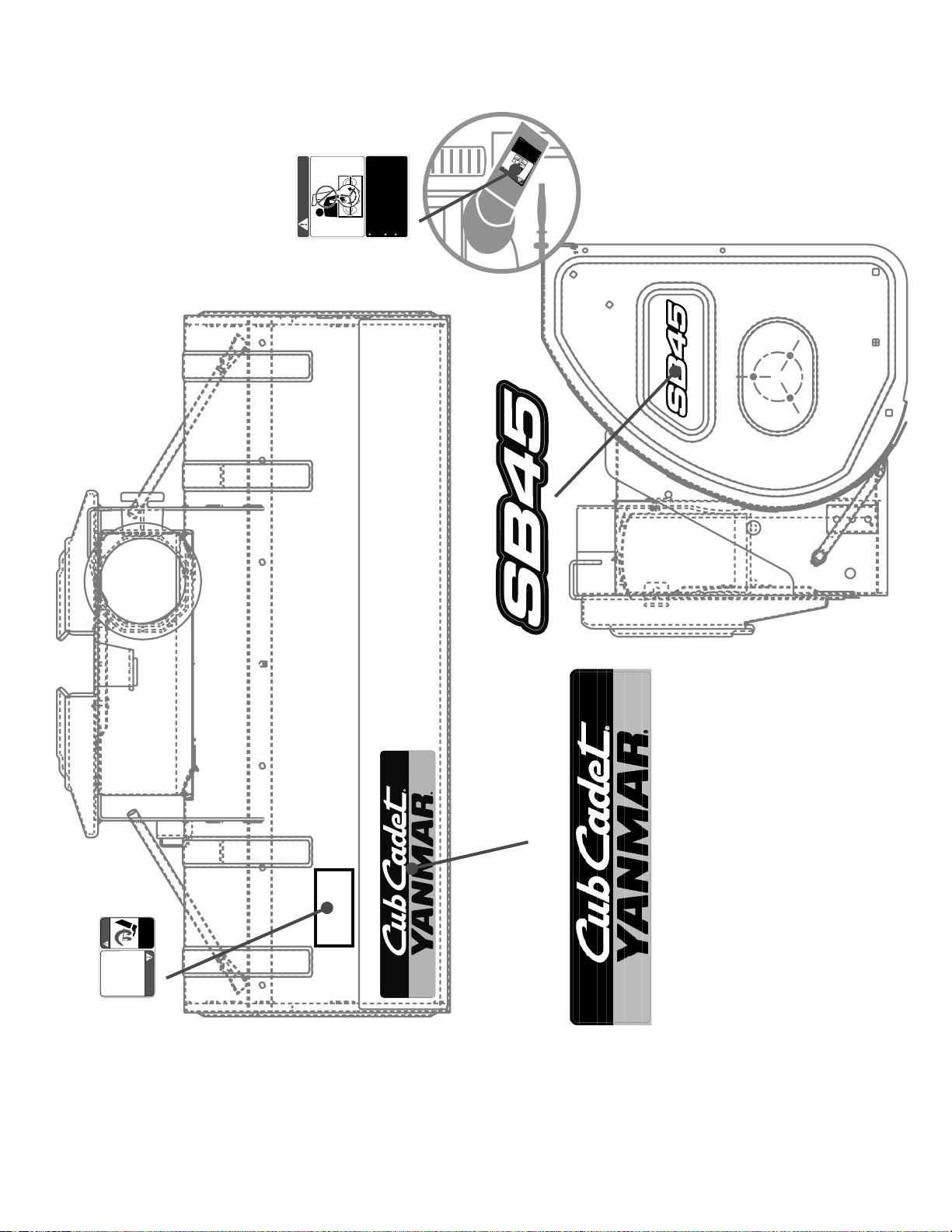
SECTION 2: LABELS FOUND ON SNOW BLOWER
DANGER
N
EVER
PUT
H
AN
D IN CHU
TE.
CO
NTAC
T WIT
H
ROTA
TING
P
ARTS
CAN AMPU
TAT
E FINGERS
AND
HA
NDS
.
DO
NOT
UN
CLOG DISCHARGE C
HUTE
WHILE
E
N
GINE IS R
UNNING
.
SHUT O
FF E
NGINE A N D R E M
AI
N ON
M
A
CHINE U NT IL
ALL MOVIN
G
PA
RTS
HAV
E
STOPPED BEFORE UNC
LOGGING.
777S30515
Cut Foot Pictorial Facing
Away From Operator
(QTY 2) 777D12773
DAN GER
DANGER
AVOID INJURY FROM
ROTATING AUGER - KEEP HANDS, FEET
AND CLOTHING AWAY.
KEEP AWAY FROM ROTATING IMPELLER AND AUGER. CONTACT WITH IMPELLE R
OR AUGER CAN AMPUTATE HANDS AND FEET.
DISENGAGE PTO, STOP ENG INE, SET PARK
BRAKE, AND REMAIN ON MA CHINE UNTIL
ALL MOVING PARTS HAVE STOPPED BEFORE
UNCLOGGING OR SERVI CING.
TO AVOID THROWN OBJECTS I NJURIES,
NEVER DIRECT DISCHARGE AT BYSTANDERS.
USE EXTRA CAUTION WHEN OPERATING ON
GRAVEL SU RFACE S.
READ OPERATOR'S MANUAL
.
FOR BALLAST REQUIREMENTS REFER TO
YOUR ATTACHMENT MANUAL.
1.
2.3.4.
5.
777D12791
Place On To p Of Auger Housing 3.5” X 15.75”
777S30524
On Edge Of Chute Read
From Chute Position
DANGER
NEVER PUT HAND IN CHUTE. CONTACT WITH
ROTATING PARTS CAN AMPUTATE FINGERS
AND HANDS.
DO NOT UNCLOG DISCHARGE CHUTE WHILE
ENGINE I S RUNNI NG.
SHU T OF F E NGI NE AND RE MAI N O N
MACHI NE U NTIL ALL MOVI NG PA RTS
HAVE STOPPED BEFOR E UNCLOGGIN G.
6
Page 7

SECTION 3: TO THE DEALER
The initial assembly and proper installation of this attachment should be completed by the Cub Cadet Yanmar dealer. Read the instructions and safety precautions found in this manual carefully.
SECTION 4: TO THE OWNER
This Operator’s Manual is an important part of your new 45” Snow Blower assembly. Contained in this manual are instructions covering installation, safe operation, and maintenance of the Model 59A40051727 snow blower assembly. Please read and understand what it says.
The Model 59A40051727 45” Snow Blower assembly is designed for use ONLY with certain Cub Cadet Yanmar tractor models. It will NOT
fit nor operate safely or properly on or with any other tractor.
References to LEFT and RIGHT indicate the left and right sides of the tractor when facing forward in the operator’s position. Reference to
the FRONT indicates the grille end; to the REAR the drawbar end.
7
Page 8

SECTION 5: CONTENTS
10
11
12
13
15
18
17
16
14
19
20
5
6
7
8
1
2
3
4
9
The snow blower attachment components are listed below along with their part numbers. Assemblies are made up of more than one part
and do not have a part number. Before beginning installation, lay all components out on a flat surface to assure everything is present.
Figure 1
1. Snow Blower Assembly N/A 1 pc
2. Chute Crank N/A 1 pc
3/4. Drive Shaft & Front Hitch PTO 819-010225 2 pc
5. Link Connecting Chain 713-04069 1 pc
6. Link Connecting Chain 713-04072 1 pc
7. Cotter Pin 714-04040 2 pc
8. Shear Pin, .375 x .181 738-04155 2 pc
(5-8 packaged with manual)
9. Chute Assembly N/A 1 pc
10. Chute Clamp 703-4080 1 pc
11. Chute Clamp Spacer 703-4079 1 pc
12. Carriage Screw, 1/4-20 x 1.00 710-0932 2 pc
13. Hex Lock Nut, 1/4-20 712-0324 2 pc
14. Flange Lock Nut, 3/8-16 712-04065 2 pc
15. Flange lock Nut, 5/16-18 712-04063 4 pc
16. Hex Screw, 5/16-18 x 1.00 710-0376 2 pc
17. Carriage Bolt, 5/16-18 x .750 710-0451 2 pc
18. Hex Screw, 3/8-16 x 3.50 710-3085 2 pc
19. Spacer, 3/8 ID x 1.0 x 2.25 750-05176 2 pc
20. Bell Washer, .340 x .872 x .060 736-0242 2 pc
(10-20 packaged in screw pack)
8
Page 9

SECTION 6: UNPACKING
Stub Shaft
Hex Screw
Hex Lock Nut
Stub Shaft
Drive Shaft
Unpacking the Snow Blower
Move the tractor and snow blower to a firm flat area large enough
to accommodate both. Allow enough room to install the snow
blower on the front of the tractor.
Carefully open the shipping container. Cut any ties or bands •
securing the snow blower, chute assembly, drive shaft, chute
crank and front hitch PTO to the shipping pallet. Remove the
snowblower, chute assembly, drive shaft, chute crank and
front hitch PTO from the shipping container.
Remove the hardware from the manual bag. Check that the •
parts in the manual bag and the parts that came attached to
the crate are correct by referring to Figure 1 and the list on
page 3.
SECTION 7: INSTALLATION
Installing the Snow Blower
If your front hitch is equipped with the angle kit, the hitch angle
cylinders will need to be replaced. Follow the instructions below to
replace the cylinders.
WARNING! Do not disconnect hydraulic lines until
all system pressure is relieved. Lower the
attachment to ground, stop engine, and operate
all hydraulic control levers
Disconnect the angle kit hoses from the tractor hydraulic 1.
couplers, and slide the hoses out of the protective sleeve.
From either side of the tractor, remove the hex lock nuts, hex 2.
screws, washers, and spacers securing the cylinder to the
hitch ‘A’ frame and mounting bracket. Reassembly and Insert
the hardware in the appropriate cylinder ends and loosely
fasten with the hex lock nut to store the cylinder assembly.
Move to the other side the tractor and repeat the above step 3.
to remove the cylinder on that side of the tractor.
Remove the cotter pins and clevis pins from the fixed length 4.
hitch arms.
From either side of the tractor, align the shorter hub of the 5.
hitch arm with mounting bracket at the bottom of the hitch
bracket, and insert the shorter clevis pin. Secure with the
cotter pin.
Raise the longer hub end of the hitch arm up between the 6.
mounting brackets on the bottom of the ‘A’ frame. Insert the
longer clevis pin and secure with the cotter pin.
Move to the other side of the tractor and repeat the previous 7.
two steps to install the fixed length hitch arm on that side of
the tractor.
The front hitch assembly is required to mount the snow blower on
the tractor. If the front hitch is installed it has to be removed for
proper installation.
Remove the front hitch as follows:
Disconnect the hitch hydraulic hoses from the hydraulic 8.
outlets of the tractor. Install the protective caps on the hitch
hoses, and remove the hoses from hose support rods. Install
the protective plugs in the hydraulic outlets.
Remove the hex cap screws and hex lock nuts securing the 9.
hitch mounting brackets to the tractor frame, and carefully
lower the hitch assembly from the tractor.
Connect the stub shaft to the backside of the ‘A’ frame 10.
bracket as shown in Figure 2. Mount the stub shaft using
the hex screws and hex lock nuts shown in Figure 2. When
mounting the stub shaft be sure that the grease fitting is
facing downward.
Figure 2
Re-install the front hitch with the stub shaft in place.11.
Mount the drive shaft the stub shaft as shown in Figure 3.12.
Figure 3
9
Page 10

Align the locking collar of the drive shaft with the Mid - PTO 13.
Front Hitch
“A” Bracket
Snow Blower
Mounting Frame
Jack Stand
Clevis Pin
Click Pin
Skid Shoe
Mid-PTO
Shaft
Locking Collar
Drive Shaft
shaft and slide the drive shaft fully onto the PTO shaft. If
necessary, compress the locking collar of the drive shaft to
ease connecting the shaft. See Figure 4. The intermediate
drive shaft must be securely connected to the Mid PTO shaft
at the lower/front of the tractor’s transmission housing.
Remove the clevis pin and click pin from the jack stand, move 17.
the jack into the third hole and replace the clevis pin and click
pin. Repeat on the other side. See Figure 6.
Figure 6
Figure 4
WARNING! Never position any part of your body
beneath tractor implements held in the raised
position only by the tractor’s hydraulic system. A
sudden loss of pressure could cause the implement to fall and could result in severe injury.
Pull the drive shaft to make sure it is locked onto the PTO 14.
shaft. The drive shaft must not pull off of the Mid PTO shaft.
NOTE: It may be necessary to turn the PTO slightly to align the
splines of the drive shaft with those of the PTO shaft.
Place the snow blower on a level surface.15.
Lower the skid shoes into the lowest operating position. See 16.
Figure 5. See the Adjustments section for how to adjust skid
shoes.
Figure 5
Start the tractor. Using the implement control lever, lower the 18.
front hitch ‘A’ frame.
Slowly driving the tractor forward, align the top of the front 19.
hitch ‘A’ frame with the side channels of the snow blower
mounting frame. Refer to Figure 7.
Figure 7
Using the implement control lever, slowly raise the front hitch 20.
while making sure the hitch ‘A’ frame engages the channels
of the snow blower mounting frame. Refer to Figure 7.
As you continue to raise the front hitch, the ramp at the top of 21.
the ‘A’ frame should push the snow blower hitch pin outward,
allowing the ‘A’ frame to fully engage the snow blower mounting frame and also aligning the hitch pin with the hole in the
front of the ‘A’ frame. The compression spring on the hitch pin
should push the pin through the ‘A’ frame hole to secure the
snow blower to the front hitch. See Figure 7.
10
Page 11

Raise the front hitch so that the snow blower is off the 22.
Stub Shaft
Drive Shaft
‘A’ Frame not show for clarity
Chute
Spacer
Clamp
Hex Screw
Chute Base
Hex Lock Nut
Mounting Holes
Bottom of Chute
Support Tube
Chute Crank
Hex Screws
Hex Bolts
ground; then stop the tractor engine and engage the parking
brake.
Check to verify that the snow blower pin is fully seated into 23.
the front hole of the ‘A’ frame. If not, push the pin rearward to
fully engage the ‘A’ frame.
Lower the blower to the ground then mount the snow blower 24.
drive shaft to the stub shaft by sliding the pulling the locking
collar back and sliding the PTO on to the stub shaft until the
PTO locks.. See Figure 8.
Mounting the Chute
NOTE: Grease the chute base before attaching. See Figure 9.
The chute was shipped with two of the chute clamps attached. To
attach the chute, place it onto the chute base and secure it with
the one remaining chute clamp using the clamp, spacer,
carriage screw and
1.0 0
See Figure 9.
1/4-20
hex lock nut from the screw pack.
1/4-20 x
Figure 8
WARNING! Do not attempt to connect the drive
shaft when the tractor engine is running. Stop the
tractor engine, disengage all PTO controls, engage the parking brake, and wait for all movement
to stop before connecting the snow blower drive
shaft.
Figure 9
Mounting the Chute Crank
To mount the chute crank you will need to two 3/8-16 x 3.50 Hex
Screws and two 5/16-18 x .1.00 hex bolts.
Mount the chute crank to the side of the chute base with the 1.
hex screws. See Figure 10.
Figure 10
Mount the support tube on the horizontal bracket below the 2.
chute base using the 5/16-18 x 1.00 bolts and flange nuts.
See Figure 10.
11
Page 12
Secure the crank assembly as shown in Figure 11 using two 3.
Flange Lock Nuts
Bell Washers
Carriage Bolts
5/16-18 x .750 carriage bolts, two .340 x .872 x .060 bell
washers and 5/16-18 flange lock nuts.
Figure 11
To adjust the skid shoes
Adjust skid shoes by loosening the six (three on each side) 1.
hex nuts, washers, and carriage bolts securing the skid
shoes to the auger housing. Refer to Figure 12.
Figure 12
Adjusting Chute Crank
It may be necessary to loosen or tighten the crank mounting
bracket prior to and after operation. To loosen the crank mounting
bracket, loosen the carriage bolts that secure the chute crank
mounting bracket to the snow blower. See Figure 11. To tighten the
clamps, tighten the carriage bolts.
Adjusting the skid shoes
Caution: It is not recommended that you
operate this snow blower on gravel as it
can easily pick up and throw loose gravel,
causing personal injury or damage to the
snow blower and surrounding property.
For close snow removal on a smooth surface, adjust the skid
shoes so that the shave plate on the bottom of the auger housing
is just off the ground.
Adjust the skid shoes to a lower position to raise the shave plate
off the ground when clearing uneven areas, such as a ribbon type
driveway or a gravel driveway
NOTE: If you choose to operate the snow blower
on a gravel surface, keep the skid shoes in position for maximum clearance between the ground
and the shave plate.
While observing the distance between the shave plate and 2.
the ground, adjust the skid shoes up or down to achieve the
desired shave plate height. See Figure 12.
Make certain the entire bottom surface of the skid shoes is 3.
against the ground to avoid uneven wear on the skid shoes;
then tighten nuts and bolts securely.
Drift Cutter
The drift cutter can be placed in the up or down position. See
Figure 13.
Figure 13
12
Page 13

SECTION 8: MAINTENANCE
Spacers
Grease Fitting
Shear Pins
Cotter Pins
Lube Chute Base
Roller Chain
Hex Nuts
Maintenance
WARNING! Before lubricating, repairing,
or inspecting, place tractor on a firm and
level surface. Place the PTO in the disengaged (OFF) position, set the parking
brake, shut engine off, and remove key to
prevent unintended starting.
Chute Directional Control
The base of the discharge chute should be lubed with lithium
grease or WD-40® once a season. See Figure 14. Spraying the
inside of the chute with lubricant is also recommended.
Auger Shaft
At least once a season, remove the shear pins and cotter pins on
the auger shaft. Oil or spray lubricant inside and on the plastic
bearings on the shaft, near the holes where the shear bolts were
removed before reattaching them and grease the fitting on the
auger gear assembly. See Figure 15.
Figure 14
PTO Lubrication
Lubricate all pivot points on the drive shaft, stub shaft and blower
drive shaft.
Figure 15
Roller Chain
The roller chain transfers power from the stub shaft to the auger
gear assembly and should be lubricated at least once a season.
To Lubricate the chain:
Remove the hex nuts that secure the chain cover. See Figure 1.
16.
Figure 16
Lubricate the chain with Cub Cadet Chain Lube.2.
Replace the cover and secure with the previously removed 3.
hex nuts.
13
Page 14

SECTION 9: SERVICE
Middle Hex Nut
Bottom Hex Nut
Top Hex Nut
Master Link
Hex Screw
Hex Bolt
Service
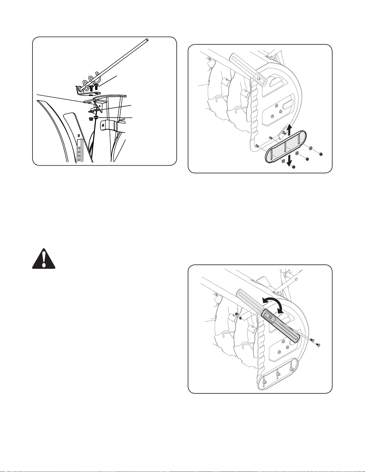
Shave Plate and Skid Shoes
The shave plate and skid shoes on the bottom of the snow blower
are subject to wear. They should be checked periodically and
replaced or flipped when necessary.
NOTE: The skid shoes on this machine have two wear edges.
When one side wears out, they can be rotated 180° to use the other
edge.
To Replace skid shoes:
Remove the six carriage bolts, hex nuts, and bell washers 1.
that secure the two skid shoes to the sides of the auger
housing. Refer to Figure 17.
Replacing or adjusting the chain
To adjust the tension on the roller chain, proceed as follows:
Loosen the three hex bolts on each side of the box. See 1.
Figure 18.
Figure 18
Figure 17
Position the new skid shoes and secure with the carriage 2.
bolts, bell washers, and hex nuts. Make certain the skid
shoes are adjusted to be level. Refer to Figure 17.
To replace shave plate:
Remove the hex nuts, bell washers, and carriage bolts that 1.
secure the shave plate to the bottom of the snow blower
housing. See Figure 17.
Remove the rear most hex nut, bell washer, and carriage 2.
bolt securing the back of each skid shoe to the sides of the
housing. Loosen the remaining hex nuts securing the skid
shoes.
Slide the shave plate out of the off-set slot at the bottom 3.
of the housing, and from between the skid shoes and side
panels of the housing.
With the mounting holes facing toward the back of the unit, 4.
slide the new shave plate into position and secure with the
fasteners removed previously.
To tighten the roller chain, loosen the top and middle hex 2.
nuts. Then while holding the bottom hex nut loosen the hex
screw. See Figure 18.
Once the desired tension is reached, re-tighten the top and 3.
middle hex nuts.
To loosen the roller chain, loosen the top and middle hex 4.
nuts. Then while holding the bottom hex nut tighten the hex
screw.
Once the desired tension is reached, re-tighten the top and 5.
middle hex nuts.
To replace the roller chain, master link or add links proceed as
follows:
Loosen the chain as instructed in step 3 above.1.
Insert a flat-head screwdriver into the master link and twist it 2.
to open up the link.
When the chain is off you can add new links or replace any 3.
damaged links.
NOTE: A replacement master link, and 1/2 link is packaged with
your manual.
14
Page 15
SECTION 10: OPERATION
Lower
Hitch
Raise
Hitch
Hitch
Float
Angle
Right
Angle
Left
Pull up Implement
Control Lock Lever
Snow Blower
Float
Right
Raise
Left
Lower
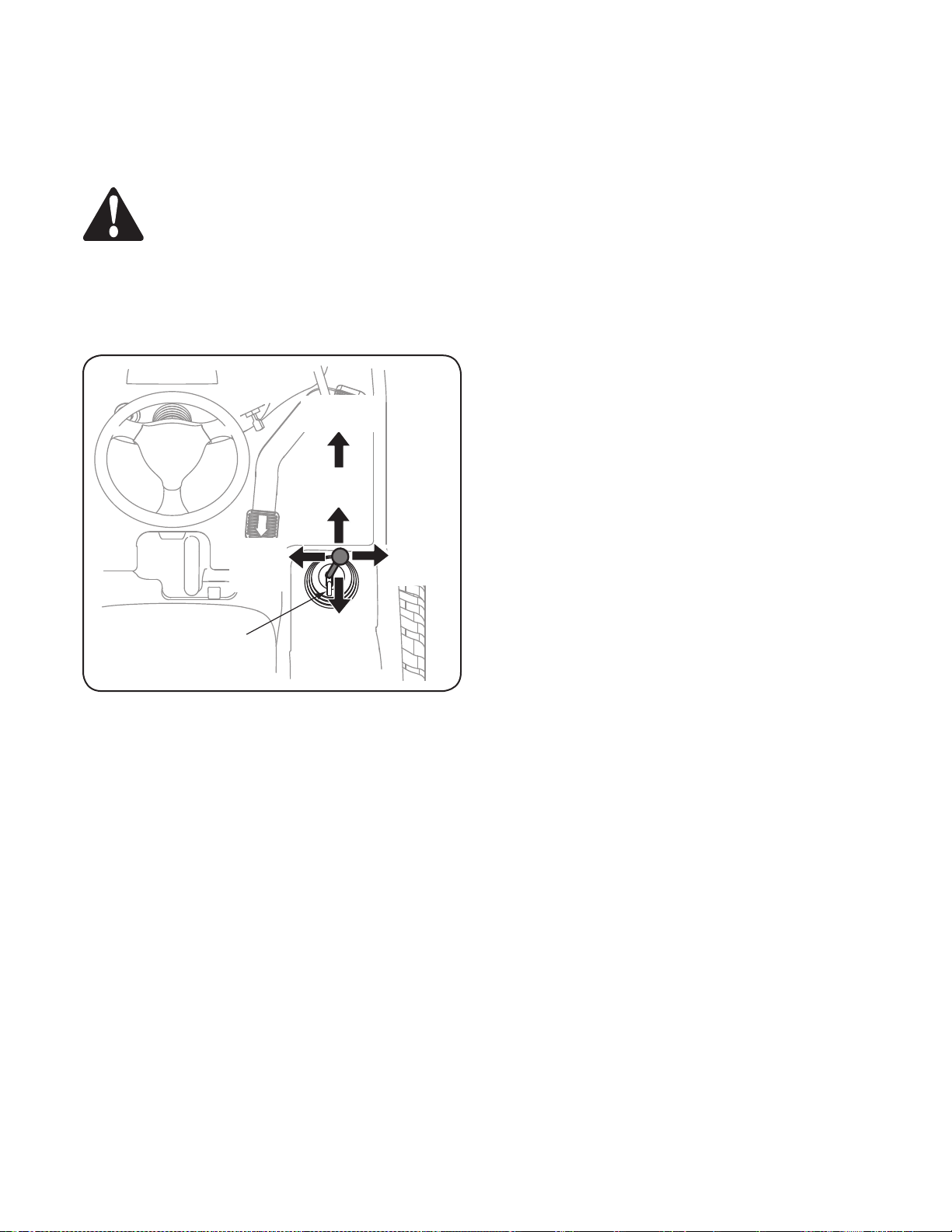
Operating the Snow Blower
The tractor’s implement control lever is used to control the movements of the front hitch.
WARNING: Always comply with all Safety
Rules before starting the tractor.
Engaging the Snow Blower
Sit on the operator’s seat.1.
Lock the parking brake.2.
Move foot pedal to the neutral position.3.
Start the engine.4.
Adjust the engine speed to 1500 rpm or lower.5.
Position PTO selector into Mid PTO position. Pull up on the 6.
PTO switch to engage the PTO.
Adjust the throttle control lever to run the implement at an 7.
intended speed.
Start the tractor’s engine and operate at a low/safe RPM.
Pull the tractor’s implement control lock lever upward to •
the unlock position. See Figure 19 and refer to the tractor
Operator’s Manual.
Figure 19
Disengaging the Snow Blower
(When the operator is seated on the operator’s seat)
Run the engine at a low speed.1.
Push down on the PTO switch.2.
NOTE: Remember that while the operator is not seated on the
operator’s seat, the PTO will disengage. When the operator attempts to engage the PTO while not seated on the operator’s seat,
the safety interlock system will engage and the engine will stop: as
a result, all the moving components will stop moving.
Pull the lever rearward to raise the snow blower. Push •
the lever forward to lower the snow blower. If the optional
hydraulic chute rotation kit is installed, pull the lever to the left
to rotate the chute to the left and push the lever to the right to
rotate the chute to the right. Refer to Figure 19.
Push the lever fully forward until it locks in the detent position •
to place the snow blower in the float position. This position
relieves hydraulic pressure to the front hitch lift cylinder,
which lowers the snow blower to the ground and allows it to
follow the contour of the ground. Use the skid shoes to adjust
the snow blower height in this position.
NOTE: The blower should be operated in the float position to
prevent excessive wear to the skid shoes.
15
Page 16

Chute Crank
Chute Clean-Out Tool
To turn the chute to the right, rotate the chute crank clockwise. To
turn the chute to the left, rotate the chute crank counter-clockwise.
Chute Clean-Out Tool
WARNING! Never use your hands to clear a
clogged chute assembly. Shut off engine and
remain behind handles until all moving parts
have stopped before unclogging.
The chute clean-out tool is conveniently fastened to the rear of the
auger housing with a mounting clip. See Figure 20. Should snow
and ice become lodged in the chute assembly during operation,
proceed as follows to safely clean the chute assembly and chute
opening:
SECTION 11: REMOVING
Removing the Snow Blower
If necessary, adjust the skid shoes so that the snow blower 1.
will stand upright in its operating position.
Select a firm and level surface to store the snow blower. 2.
Using the implement control lever, lower the snow blower
until just contacting the ground. Stop the tractor engine and
engage the parking brake before dismounting.
Remove the clevis pin and click pin from the jack stand, move 3.
the jack into the appropriate hole that will make the snow
blower level then replace the clevis pin and click pin. See
Figure 3.
Pull the hitch pin forward to withdraw it from the hitch ‘A’ 4.
frame hole. Rotate the hitch pin so that does not align with
the hole in the hitch A frame. Refer to Figure 7.
Disconnect the snow blower shaft. 5.
Start the tractor and lower the front hitch ‘A’ frame so that 6.
it disengages the snow blower mounting frame. Back the
tractor away from the snow blower. Refer to Figure 7.
Reposition the hitch pin to engage the holes in the snow 7.
blower mounting frame.
Turn off the PTO.1.
Stop the tractor and engage the parking break.2.
Remove the clean-out tool from the clip which secures it to 3.
the rear of the auger housing.
Use the shovel-shaped end of the clean-out tool to dislodge 4.
and scoop any snow and ice which has formed in and near
the chute assembly.
Re-fasten the clean-out tool to the mounting clip on the rear 5.
of the auger housing, reinsert the ignition key and start the
tractor engine.
Figure 20
16
Page 17

NOTES PAGE
17
Page 18

SECTION 12: PARTS LIST
Snow Blower
18
Page 19

Ref.
Part
No.
Number Description Qt y.
1. 05244B Bearing Housing 10
2. 603-04598 Housing Assembly 1
3. 603-04600 Chute Assembly 1
4. 603-04673 Bracket Assembly 1
5. 603-04689 Chain Cover 1
6. 618-04800 Auger Gear Assembly 1
7. 684-0090B Impeler Assembly 1
8. 684-04056 Chute Cleanout tool 1
9. 684-04329 Spiral Assembly, RH 3
10. 684-04330 Spiral Assembly, LH 3
11. 703-05048 Rubber Chute Bracket 1
12. 703-06972 Chute Deflector 1
13. 703-07066 Stand Bracket 2
14. 703-07168 Spacer Plate 2
15. 703-4079 Chute Clamp Spacer 3
16. 703-4080 Chute Clamp 3
17. 710 -0376 Hex Screw, 5/16-18 x 1.00 2
18. 710-0451 Carriage Bolt, 5/16-18 x .750 13
19. 710 -0514 Hex Screw, 3/8-16 x 1.00 6
20. 710-0726 Hx. Wshr. Screw, 5/16-20 x .750 1
21. 710 -093 2 Carriage Screw, 1/4-20 x 1.00 6
22. 710-0946 Machine Screw, 1/4-20 x .625 3
23. 710 -1207 Hex Screw, 5/16-18 x 3.50 2
24. 710-3008 Hex Screw, 5/16-18 x .75 1
25. 710- 3015 Hex Screw, 1/4-20 x .75 2
26. 710-3038 Hex Screw, 5/16-18 x .875 7
2 7. 710-3085 Hex Screw, 3/8-16 x 3.50 2
28. 710-3105 Carriage Bolt, 5/16-18 x .875 2
29. 710-316 8 Carriage Bolt, 3/8-16 x 1.00 2
30. 710 -317 8 Carriage Bolt, 3/8-16 x .75 4
31. 710 -3180 Hex Screw, 5/16-18 x 1.75 1
32. 710- 3251 Hex Screw, 5/16-18 x 1.75 1
33. 7 11- 017 3 Clevis Pin 2
34. 711- 0510 7 Input Shaft 1
35. 712- 0130 Hex Lock Nut, 3/8-16 6
36. 712-0298 Jam Nut, 1/4-20 2
37. 712-0 324 Hex Lock Nut, 1/4-20 6
38. 712-04063 Flange Lock Nut, 5/16-18 31
39. 712-04064 Flange Lock Nut, 1/4-20 7
40. 712- 04065 Flange Lock Nut, 3/8-16 2
41. 712-3010 Hex Nut, 5/16-18 8
42. 713- 04066 Sprocket 1
43. 713- 04067 Sprocket 1
44. 713-04068 Roller Chain 1
45. 713-040 69 Chain Connecting Link 2
46. 713- 04072 Chain Half Link 1
47. 714- 0126 Hi-Pro Key 1
48. 714- 0135 Woodruff Key 1
Ref.
Part
No.
Number Description Qt y.
49. 714 -0145 Click Pin 2
50. 714-04040 Bow-Tie Cotter Pin 8
51. 714 -04 059 Hi-Pro Key 1
52. 714-0507 Cotter Pin 1
53. 7 15 -0 118 Spirol Pin, 5/16-1.75 2
54. 715-0129 Spirol Pin, .125 x .812 4
55. 715-0138 Roll Pin, 1/8 x .63 1
56. 715-30 03 Spirol Pin 1
57. 716 -0102 Snap Ring 2
58. 717-04 641 Drive Shaft 1
59. 720-0201A Chute Crank Knob 1
60. 72 0 -0241 Wing Nut 2
61. 726- 0100 Push Cap 1
63. 731-05163 Spcer., 1.50 OD x 1.00 ID x 1.00 12
64. 732-3091 Compression Spring, .57 x 2.09 1
65. 735-04154 Rubber Deflector 1
66. 736 -0105 Washer, .401 x .870 x .063 6
6 7. 736 -0123 Flat Washer, .349 x 1.16 x .064 2
68. 736- 014 0 Flat Washer, .385 x .62 x .063 1
69. 736-0242 Bell Washer, .340 x .872 x .060 8
70. 736-0250 Flat Washer, 1.00 x 1.75 x .107 4
71. 736-0270 Bell Washer, .265 x .75 x .062 2
72. 736-0343 Flat Washer, .330 x 1.25 x .120 1
73. 736-0451 Saddle Wshr., .320 x.93 x .060 3
74. 736-3072 Flat Washer, .36 x .93 x .110 6
75. 738-0255 Shoulder Screw, .375 x .181 4
76. 738 -04155 Shear Pin, .25 x 1.75 8
7 7. 73 8- 04159 Spiral Axle 1
78. 741-04024 Self-Aligning Bearing 1
79. 741- 04132A Self-Aligning Bearing 2
80. 741- 0475 Plastic Bushing 3
81. 741- 04 94 Flnge. Bshg., 1.05 ID x 1.16 OD 12
82. 747-04188 Chute Crank Rod 1
83. 747-0481A Eye Bolt, 5/16-18 x 3.0 2
84. 747- 09 03 Chute Crank Rod, .375 x 36.75 1
85. 747- 3427 Front Hitch Pin 1
86. 749-04549 Crank Support Tube 1
87. 749-04552 Support Tube 1
88. 750-04020 Spacer, 1.004 x 1.375 x .25 2
89. 75 0- 05176 Spacer, 3/8 ID x 1.0 x 2.25 2
90. 784-5076 Gear Housing Support Bracket 1
91. 784-5123 Chute Crank Bracket 1
92. 784-5149 Bracket Assembly Joint 2
93. 784-5401 Chute Crank Assembly 1
94. 784-5696B Shave Plate 1
95. 784-5697 Skid Shoe 2
96. 784-5710 Support Plate 1
97. 790-00181 Blade Guide 2
19
Page 20

6
2
5
10
7
11
1
4
3
9
8
PTO/Drive System
Ref.
Part
No.
Number Description Qt y.
1. 710- 0376 Hex Screw, 5/16-18 x 1.00 2
2. 711 -16 23 Spline Shaft 1
3. 712-0429 Hex Lock Nut, 5/16-18 2
4. 716-0102 Shaft Snap Ring 2
5. 716-018 8 Retainer Ring 1
6. 717- 046 42 Drive Shaft 1
7. 719 -3172 Shaft 1
8. 721-0462 Grease Seal, 1.31 x 1.00 1
9. 737-3000 Lube Fitting 1
10. 741- 0131 Ball Bearing, 1.00 ID x 2.00 OD 1
11. 741-03 63 Bearing, 1.000 x 1.3125 x .7500 1
20
 Loading...