

Page 1

DESIGNED
PTO DRIVEN -
TO FIT:
MODEL YEAR:
2014-Newer
COLLECTION SYSTEM
GRASS COLLECTION SYSTEM
MODEL #
ALTERNATE
MODEL #
21120901B
59A30045150
Series:
Z-Force Series
- 48”, 54” & 60” DECKS
LZ Models:
LZ 48 - 53ATDAGB050
LZ 60 - 53ANDAGD050
SZ Models:
SZ 48 - 53ATDFJB050
SZ 60 - 53ANDFJD050
OPERATOR’S MANUAL
ASSEMBLY OPERATION MAINTENANCE
MANUAL PART#: Q04 5 Rev: 3 - 12/12/20177
LX Models:
LX 48 - 17AIDAUB010
LX 54 - 17AIDAUC010
LX 60 - 17AIDAUD010
SX Models:
SX 48 - 17AIDGJB010
SX 54 - 17AIDGJC010
SX 60 - 17AIDGJD010
Page 2

RESIDENTIAL BAGGING SYSTEM
TABLE OF CONTENTS
SECTION PAGE
Safety - - - - - - - - - - - - - - - - - - - - - - - - - - - - - - 2
Safety Alert Symbols- - - - - - - - - - - - - - - - - - - - - - 3
Warranty - - - - - - - - - - - - - - - - - - - - - - - - - - - - - 4
I INTRODUCTION AND DESCRIPTION - - - - - - - - - - - - 5
1-1 Introduction - - - - - - - - - - - - - - - - - - - - - - - - - 5
1-2 Description - - - - - - - - - - - - - - - - - - - - - - - - - 5
II INSTALLATION FOR USE - - - - - - - - - - - - - - - - - - - - - 5
2-1 Preparation Of Mower - - - - - - - - - - - - - - - - - - 5
2-2 Rear Frame Bracket & Right Frame
Bracket Installation - - - - - - - - - - - - - - - - - - - - 6
2-3 Exhaust Diverter Installation - - - - - - - - - - - - - - 7
2-4 PTO Mount Plate Component Installation- - - - - 7-8
2-5 PTO Assembly Installation - - - - - - - - - - - - - - - 9
2-6 Belt Installation/Removal & Adjustment - - - - - - - 9
2-7 Lower Mount Tube Installation - - - - - - - - - - - - - 10
2-8 Upper Frame Assembly Installation- - - - - - - - - - 10
2-9 Top Assembly to Upper Frame
Assembly Installation- - - - - - - - - - - - - - - - - - - 10
2-10 Inlet Installation- - - - - - - - - - - - - - - - - - - - - - 10
2-11 Hinge Kit Installation- - - - - - - - - - - - - - - - - - - 10
2-12 Blower Cone Installation - - - - - - - - - - - - - - - - 11
2-13 Boot To Mower Deck Installation- - - - - - - - - - - 12
SAFETY
SECTION PAGE
2-14 Length of Hose Adjustment - - - - - - - - - - - - - - 13
2-15 Upper Hose Installation - - - - - - - - - - - - - - - - 13
2-16 Lower Hose To Blower Cone Installation- - - - - - 13
2-17 Lower Hose To Boot Installation - - - - - - - - - - - 13
2-18 Installation/Removal Of Collection Bags - - - - - - 14
2-19 Weight Kit Installation- - - - - - - - - - - - - - - - - - 15
2-20 Safety Interlock Harness Installation - - - - - - - - 16
Safety Interlock Harness Wiring Diagram - - - - - - - - 17
2-21 Impeller Blade Removal/Replacement - - - - - - - 18
Exploded Views & Parts List - - - - - - - - - - - - - - - 19-22
Safety Decals - - - - - - - - - - - - - - - - - - - - - - - - - - 23
III OPERATING INSTRUCTIONS - - - - - - - - - - - - - - - - - - 24
3-1 General Safety - - - - - - - - - - - - - - - - - - - - - - - 24
3-2 Operation & Tips On Mowing - - - - - - - - - - - - - - 24
3-3 Disengagement Of The PTO Assembly - - - - - - - 24
3-4 Unloading The Collection System - - - - - - - - - - - 24
IV MAINTENANCE - - - - - - - - - - - - - - - - - - - - - - - - - - 24-25
4-1 Maintenance Checklist - - - - - - - - - - - - - - - - - - 24
4-2 Lubrication- - - - - - - - - - - - - - - - - - - - - - - - - - 25
V PARTS AND SERVICE - - - - - - - - - - - - - - - - - - - - - - - 25
5-1 Parts And Service Information - - - - - - - - - - - - - 25
Torque Specifications - - - - - - - - - - - - - - - - - - - - - 26
Notes- - - - - - - - - - - - - - - - - - - - - - - - - - - - - - - - 27
1. Read the operator’s manual carefully and familiarize yourself with the proper use of your attachment. Do not allow
anyone who is not acquainted with the Safety Instructions to use your attachment.
2. Know the controls and how to stop them quickly. READ THE OPERATOR’S MANUAL!
3. Do not allow children to operate the machine. Do not allow adults to operate it without proper instruction.
4. Be especially watchful of children and pets entering into the area while operating.
5. Keep your eyes and mind on your machine while mowing or operating your attachment. Don’t let others distract
you.
6. Do not attempt to operate your machine when not in the driver’s seat.
7. Always shut off blades and engine when emptying the container.
8. Stop machine, shut off deck attachment, set parking brake, shut off engine and remove ignition key before
removing clogs, removing or replacing hose, boot, blower cone, or performing any maintenance.
9. Mow across the face of slopes (not more than 10 degrees); never up and down the face.
10. It is recommended that the container be emptied when half full while operating on slopes. Start mowing on slopes
when the container is empty.
11. Inspect your lawn and remove any foreign objects before mowing. Never deliberately run the mower across any
foreign object.
12. Wear hearing protection.
13. Wear eye protection to prevent debris from getting into your eyes.
2
2017 (v1.0)
Page 3

SAFETY
WARNING! NEVER operate the mower unless the discharge guard and either the deflector assembly or
the vacuum collector adapter are fastened securely in place.
WARNING! Do not work around the mower deck boot or the blower area until you are certain that the mower
blades and the blower impeller have stopped rotating.
WARNING! To avoid serious injury, perform maintenance on the vacuum collector; ONLY AFTER
STOPPING THE MOWER’S ENGINE AND WAITING FOR ALL MOVING PARTS TO COME TO A
COMPLETE STOP. Set the parking brake. Always remove the ignition key before beginning maintenance.
WARNING! For your own personal safety, ALWAYS mow ACROSS the face of slopes and
NEVER UP and DOWN the face. NEVER attempt to mow excessively steep slopes, and use
caution when turning on any slope.
Safety Alert Symbol
This Safety Alert Symbol means: “ATTENTION! BECOME
ALERT! YOUR SAFETY IS INVOLVED!”
This symbol is used to call attention to safety precautions that
Should be followed by the operator to avoid accidents. When
you see this symbol, carefully read the message that follows
and heed its advice. Failure to comply with safety precautions
could result in death or serious bodily injury.
!
Safety Signs
The signal words DANGER, WARNING, and CAUTION are used on the equipment safety signs. These words
are intended to alert the viewer to the existence and the degree of hazard seriousness.
This signal word indicates a potentially hazardous situation which, if not
DANGER
!
White letters on RED
WARNING
!
Black letters on ORANGE
avoided, will result in death or serious injury.
This signal word indicates a potentially hazardous situation which, if not
avoided, could result in death or serious injury.
It may also be used to alert against unsafe practices.
CAUTION
!
Black letters on YELLOW
This signal word indicates a potentially hazardous situation which, if not
avoided, will result in minor or moderate injury.
It may also be used to alert against unsafe practices.
2017 (v1.0)
3
Page 4

PECO LIMITED WARRANTY FOR NEW PRODUCTS
A. WHAT IS UNDER WARRANTY?
PECO extends the following warranties to the original purchaser of each new PECO consumer product subject
to the following limitations.
1. PRODUCT WARRANTY: Any part of any consumer product, which is defective in material or
workmanship as delivered to the purchaser will be repaired or replaced, as PECO elects, without charge for
parts or labor, if the defect appears within 12 months from the date of delivery of the product to the original
purchaser. ALL DEFECTIVE PARTS MUST BE RETURNED TO PECO FOR INSPECTION TO DETERMINE
VALIDITY OF WARRANTY CLAIMS. Freight and mailing will be borne by the customer.
2. PARTS REPLACED DURING WARRANTY: Any new PECO part which is furnished in performance of
this warranty and is defective in material or workmanship as delivered to the purchaser will be repaired or
replaced, before the expiration of the original warranty period, whichever is later.
3. COMMERCIAL USE: Products put to personal use around a single household or residence is considered
'Residential'; Products put to any business use (agricultural, commercial, or industrial) or used at multiple
locations is considered 'Commercial.' Products designated as 'Commercial' are warrantied for 12 months
from the date of delivery of the product to the original purchaser when used for in commercial applications.
Products designated as 'Residential' are warrantied for 90 days from the date of delivery of the product to the
original purchaser when in commercial applications.
B. SECURING WARRANTY ADJUSTMENTS
Call PECO for Return Authorization. Damaged or broken parts other than engines or batteries, must be
returned to New PECO, Inc. at 10 Walden Drive, Arden, NC 28704 before any warranty adjustment can be
authorized. At the time of requesting warranty adjustment, the purchaser must present evidence of the date of
delivery of the product. The purchaser shall pay any charge for the product to and from Arden, NC.
C. ITEMS NOT COVERED BY PECO WARRANTY
Engines and batteries attached to PECO products are covered under a separate warranty by the respective
manufacturer.
D. UNAPPROVED ALTERATION OR MODIFICATION
All obligations of New PECO, Inc. under this warranty shall be terminated if products are altered or modified in
ways not approved by New PECO, Inc.
E. ACCIDENTS AND NORMAL MAINTENANCE
The warranty covers only defective material and workmanship. It does not cover depreciation or damage
caused by normal wear, accident, improper use or abuse of products. The cost of normal maintenance and
normal replacement of service items such as belts, cutting blades, hoses, etc., which are not defective shall be
paid for by the purchaser.
F. NO REPRESENTATIONS ADDITIONAL WARRANTIES, DISCLAIMER
Neither New PECO, Inc. nor any company affiliated with it makes any warranties, representations or promises
as to the quality of performance of its products other than those set forth herein. Except as described above,
New PECO, Inc. makes no other warranties AND SPECIFICALLY DISCLAIMS ANY AND ALL IMPLIED
WARRANTIES OF FITNESS AND MERCHANTABILITY.
G. PRODUCTS USED FOR RENTAL OR LEASE PURPOSES ARE WARRANTIED FOR 45 DAYS
FROM DATE OF ORIGINAL SALE ONLY
H. REMEDIED EXCLUSIVE
The only remedies the purchaser has in connection with the breach or performance of any warranty on New
PECO, Inc. consumer products are set forth above. In no event will PECO be liable for special incidental or
consequential damages.
1. NO SERVICE CENTER WARRANTY
The selling Service Center makes no warranty on his own on any item warranted by New PECO, Inc. unless he
delivers to purchaser a separate written warranty certificate specifically warranting the item. The dealer has no
authority to make any representation or promise on behalf of PECO or to modify the terms of this warranty in
any way.
4
2017 (v1.0)
Page 5
Section I - INTRODUCTION &
PRESS
PRESS
DESCRIPTION
1-1 Introduction
Your grass collection system has been designed to give
you a low maintenance, simple, and effective way to
collect the grass clippings from your mower. This manual
is provided to give you the necessary instructions to
properly mount and operate the collection system on
your mower. Please read this manual thoroughly.
Understand what each control is for and how to use it.
Observe all safety decal precautions on the machine and
noted throughout the manual.
NOTE: All references made to right, left, front, rear, top
or bottom are as viewed from the normal operator’s
position on the mower.
1-2 Description
The grass collection system is designed for turf
maintenance where there is a need to collect the grass
clippings as the mower cuts the turf. It is also used for
picking up leaves in pre-season and post-season cleanup. The blower, mounted on the right side of the unit,
uses a belt and gearbox system from the engine PTO
shaft. Drive train protection comes through belt slippage.
The blower draws grass clippings from the discharge
area of the cutting deck back to the (2) - 4 cubic foot
collection bags P#(G0003) at the rear portion of the
mower frame. The operator can engage the blower with
a spring-lock engagement handle on the right side of the
unit. Once the bags are full with clippings, they can be
easily released for dumping.
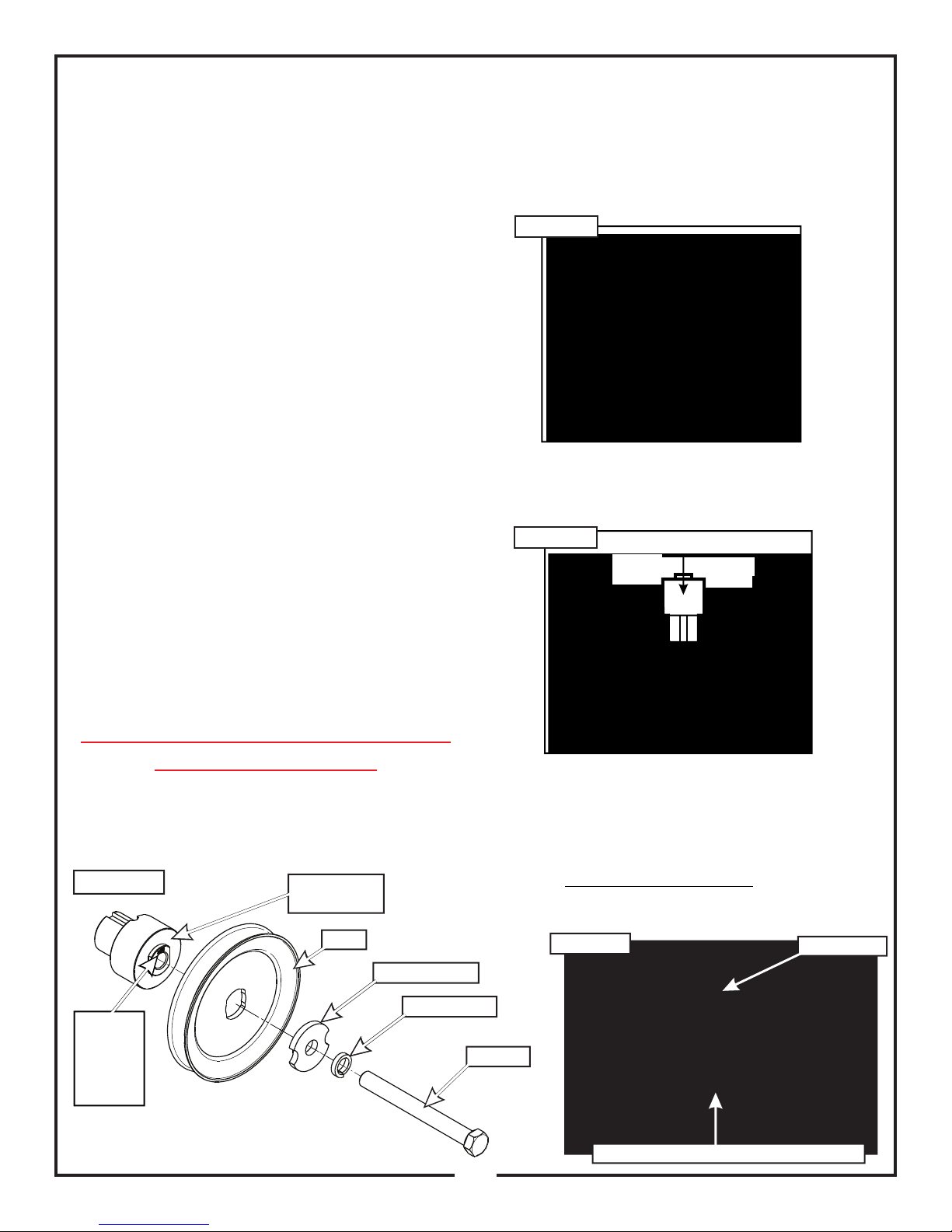
2-1 Preparation Of Mower
From the underside of the engine, disconnect the wiring
harness attached to the electric clutch. Remove the bolt
and electric clutch from the mower. Refer to Figure 2-1a.
Remove the D-drive spacer using an arbor press or
equivalent. On removal, adjacent bearing OUTER race
must be supported or bearing damage may occur. Refer
to Figure 2-1b.
Figure 2-1a
The engine pulley assembly must be installed using an
arbor press or equivalent. Upon Installation, opposite
bearing inner race must be supported or bearing
damage may occur. Refer to Figure 2-1c.
Figure 2-1b
Section II - INSTALLATION FOR USE
Collection System May Require
Dealer Installation!
Please refer to Page 16 for further details.
Figure 2-1c
Pulley
Bushing
Number
Located
Here
Engine Pulley
Bushing
Pulley
Clamp Washer
Lock Washer
Engine Pulley Bushing Installation
Once the Engine Pulley Bushing P#(S0220) is installed,
reattach the clutch assembly to the mower and then
review Figure 2-1c. To assemble and fasten the Engine
Pulley, align Pulley hole to the Engine Pulley Bushing
and fasten using (1) Clamp Washer P#(K0278), (1)
7/16” lock washer P#(K0140), and 7/16”-20 x 4” hex bolt
P#(K0359). Torque the bolt to 55 ft./lbs. The added
pulley will power the collection system and should
resemble Figure 2-1d when installed.
Figure 2-1d
Hex Bolt
Electric Clutch
5
5
Engine Pulley Assembled Into Electric Clutch
Page 6

2-2 Rear Frame Bracket & Right
Frame Bracket Installation
Remove hardware from the rear guard assembly, shown
circled in Figure 2-2A.
Secure the rear frame bracket P#(A1204) to the rear
guard of the mower, using (4) 5/16”-18 x 1” phillips truss
head zinc machine screws P#(K0504) and (4) 5/16”-18
flange nuts P#(K1178). Refer to Figure 2-2b.
Secure the right frame bracket P#(A1208) to the rear
guard of the mower using (2) 5/16-18 x 1-1/2” HHCS
P#(K1157) and (2) 5/16”-18 nylon flange locknuts
P#(K2516). Refer to Figure 2-2b.
Figure 2-2a
Remove
Hardware
Rear
Guard
Assembly
Figure 2-2b
Rear Frame
Bracket
(4) 5/16”-18
Flange Nuts
(2) 5/16”-18
Locknuts
Right Frame
Bracket
(4) 5/16”-18 x 1”
Phillips Truss Head
Zinc Machine Screw
(2) 5/16”-18 x 1-1/2”
Hex Bolts
6
Page 7
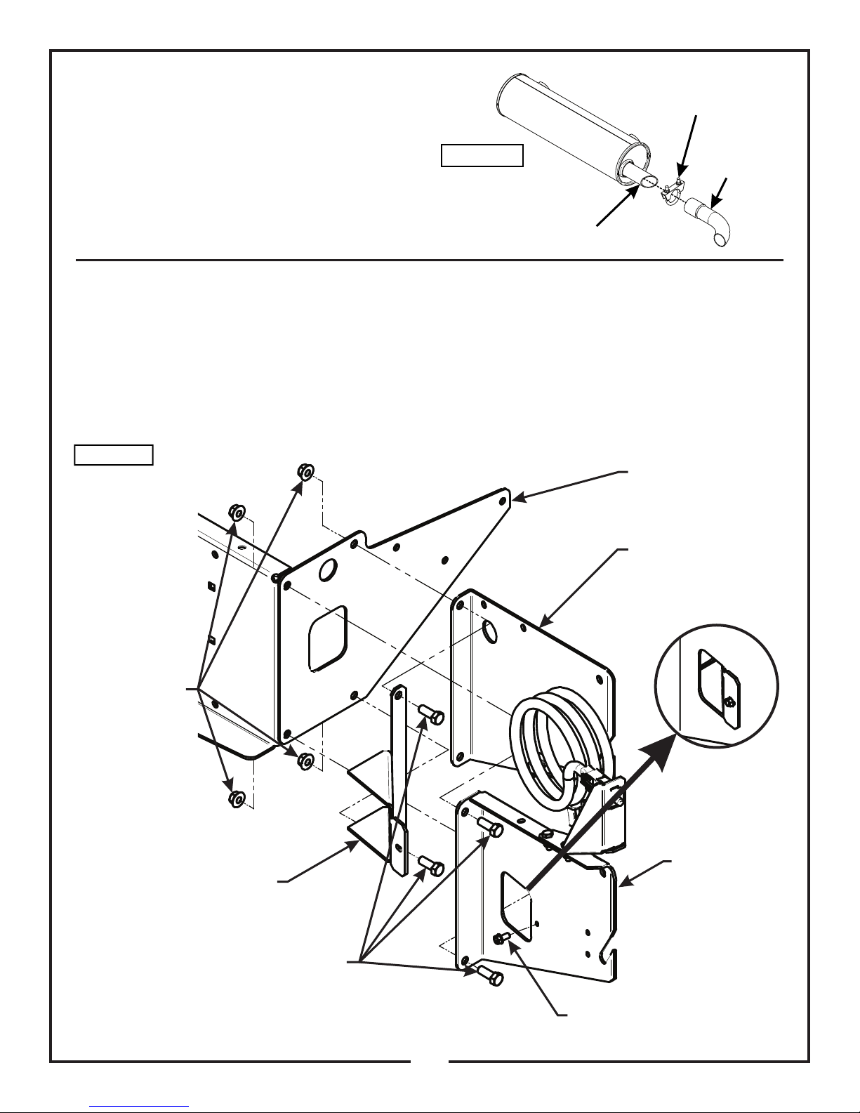
2-3 Exhaust Diverter Installation
For LZ & SZ Models Only With Round Exhaust Pipe -
Exhaust
Clamp Kit
Attach (1) exhaust diverter P#(B0693) to the muffler
exhaust pipe. Secure the diverter using (1) exhaust
clamp kit P#(X1064). Do not tighten the exhaust clamp
until the PTO mount plate components have been
installed and the exhaust diverter has been positioned
correctly. Refer to Figure 2-3a for positioning.
Figure 2-3a
Muffler
Exhaust Pipe
Exhaust
Diverter
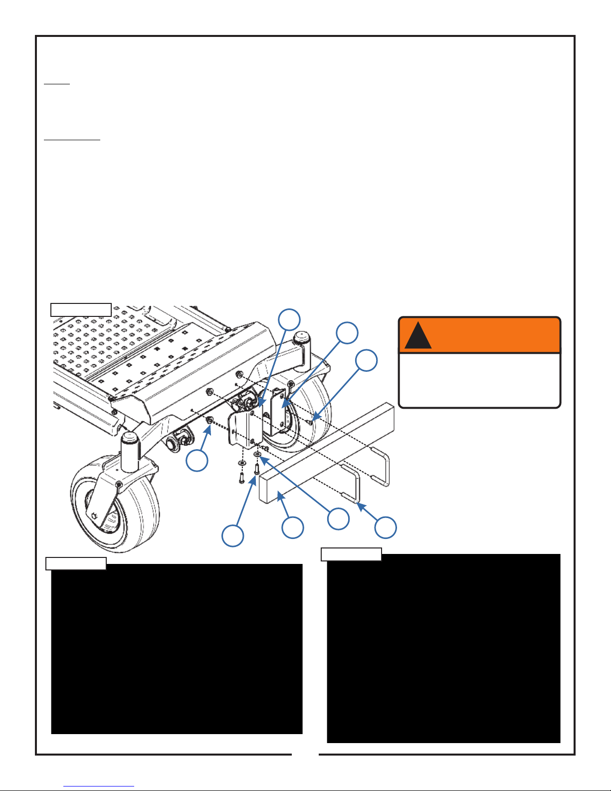
2-4 PTO Mount Plate Component Installation
Secure the right PTO mount plate P#(B0859) & exhaust diverter P#(C0091) to the right frame bracket using (2) 3/8”16 x 1” HHCS P#(K1191) and (2) 3/8”-16 nylon flange lock nuts P#(K2038). Secure the left PTO mount assembly
P#(A1991) to the right frame bracket using (2) 3/8”-16 x 1” HHCS P#(K1191) and (2) 3/8”-16 nylon flange lock nuts
P#(K2038). Do not tighten the hardware completely until the all the components have been installed. Secure the
exhaust diverter P#(C0091) to the left PTO mount assembly using (1) 1/4” self tapping screw P#(K0353). Refer to
Figure 2-4a.
Figure 2-4a
Right Frame
Bracket
Right PTO
Mount Plate
(4) 3/8”-16
Nylon Flange
Lock Nuts
Exhaust Diverter
(LX & SX Models Only)
Left PTO
Mount
Assembly
(4) 3/8”-16 x 1”
HHCS
1/4” Self Tapping Screw
7
Page 8
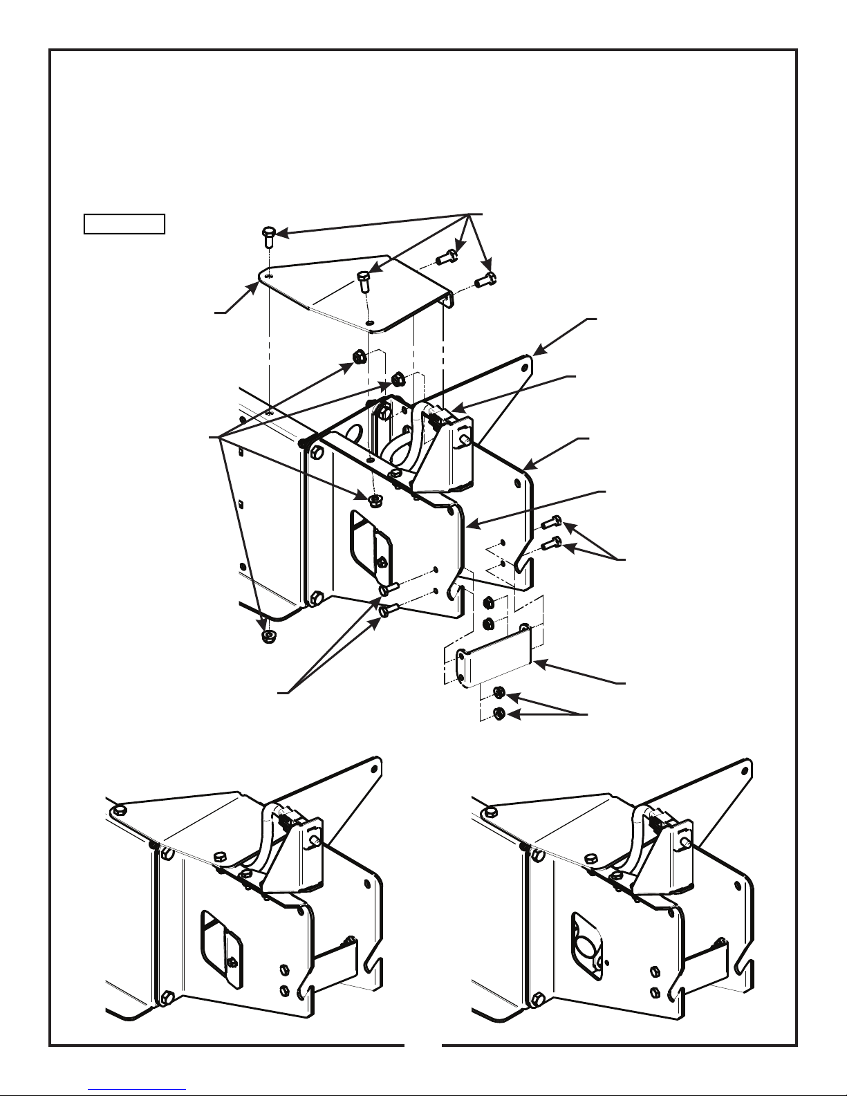
2-4 PTO Mount Plate Component Installation (Cont.)
Secure the PTO stiffener bracket P#(B0861) to the rear frame bracket and left and right PTO mount plates using
(4) 5/16”-18 x 3/4” HHCS P#(K1153) and (4) 5/16”-18 nylon flange locknuts P#(K2516). Secure the PTO stop
plate P#(B0733) to the left and right PTO mount plates using (4) 1/4”-20 x 3/4” HHCS P#(K1222) and (4) 1/4”-20
nylon flange locknuts P#(K2014). Tighten all PTO mount plate component hardware at this time. Refer to Figure
2-4b.
Figure 2-4b
PTO Stiffener
Bracket
5/16”-18 Nylon
Flange Lock Nuts
5/16”-18 x 3/4” HHCS
Rear Frame Bracket
Route Safety Interlock
Harness Through Right
PTO Mount Plate
Right PTO Mount Plate
Left PTO Mount Plate
1/4”-20 x 3/4”
HHCS
1/4”-20 x 3/4”
HHCS
Completed Assembly
For LX & SX Models
PTO Stop Plate
1/4”-20 Nylon Flange
Lock Nuts
Completed Assembly
For LZ & SZ Models
8
Page 9
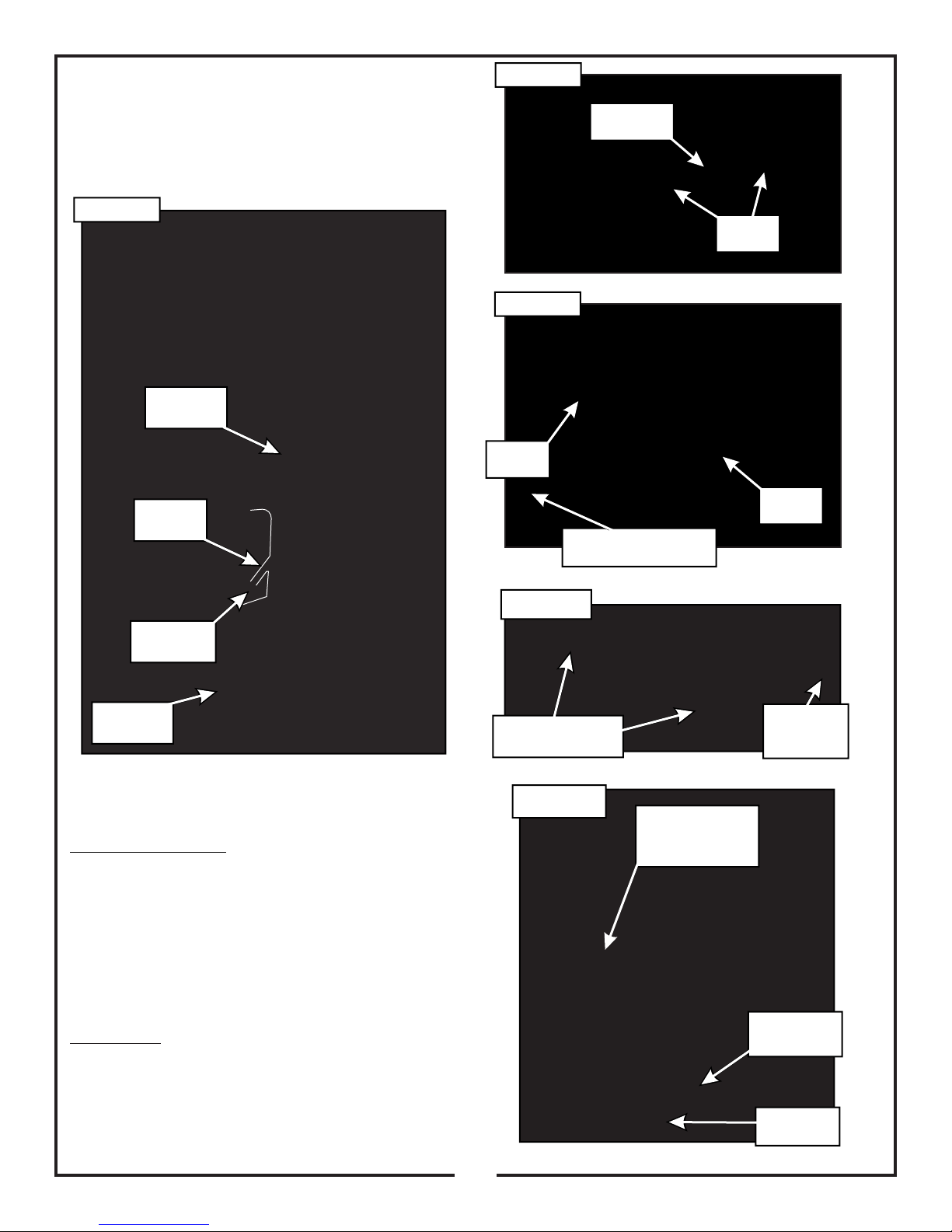
2-5 PTO Assembly Installation
Figure 2-6a
Remove (3) 1/4”-20 x 1/2” HHSTS P#(K0353) from the
PTO assembly to remove the belt guard. Insert the
mount rod of the PTO assembly P#(A1842), into the
mounting slots on the PTO mount plates, as shown in
Figure 2-5.
Figure 2-5
PTO
Assembly
Mounting
Slots
Gear Box
Base Plate
Loosen
Bolts
Figure 2-6b
Loosen
Bolt
Loosen
Bolt
Slide Gearbox Base
Plate Toward Engine
PTO Assy.
Mount Rod
Remove
Belt Guard
2-6 Belt Installation/Removal &
Adjustment
Installation/Removal: Loosen the (4) 5/16”-18 x 3/4”
HHCS P#(K1153) that secure the gear box base plate.
Loosen the adjustment bolt (1) 3/8”-16 x 2” hex bolt
P#(K0348). Slide the gearbox towards the mower until
there is enough clearance for the kevlar belt to slide over
both the engine and gearbox pulleys. Install the A76K
kevlar belt P#(M0274). Pivot PTO assembly to align
holes, then fasten by inserting (1) PTO mount pin
P#(B0274). Secure the mount pin using (1) hair pin clip
P#(K0086). Refer to Figures 2-6a through 2-6d.
Adjustment: To adjust the belt tension, turn the
adjustment bolt clockwise until there is 1” of deflection,
with 10-11lbs of pressure applied to the center of the
belt. When proper tension is achieved, tighten the (4)
5/16”-18 x 3/4” HHCS that secure the gear box base
plate to the PTO assembly. Replace the belt guard and
(3) 1/4”-20 x 1/2” HHSTS. Refer to Figure 2-6d.
Figure 2-6c
Wrap Belt Around
Both Pulleys
Figure 2-6d
Loosen
Adjustment
Bolt
PTO Mount Pin
Secured w/
Hair Pin Clip
Adjustment
Bolt
Replace
Belt Guard
9
Page 10

2-7 Lower Mount Tube Installation
Secure the (2) lower mount tubes P#(B0640) to the rear
frame bracket using (2) 5/16”-15 u-bolts P#(K1098) and
(4) 5/16”-18 nylon flange locknuts P#(K2516) PER
TUBE. Refer to Figure 2-7.
Figure 2-7
Lower Mount
Tubes
(4) 5/16”-18
Locknuts
PER
BRACKET
Figure 2-9
Clevis
Rue Ring
Pin
Cotter Pin
Clip
Top Assembly
Hex
Bolt
Flange
Locknut
Flat
Washer
(2) 5/16”-18 x 2-1/2” HHCS
Inlet
(2) 1/4” Flat Washers
(2) 5/16”-18 Locknuts
2-10 Inlet Installation
Insert the Inlet P#(V0019) into the hole on the top
assembly from the inside and then snap the inlet into
place. The inlet should pivot freely about the hole.
Nylon
(2) 5/16”-18
U-Bolts
Rear Frame
Bracket
PER BRACKET
2-8 Upper Frame Assembly
Installation
Lift the upper frame assembly P#(A1114) into position,
and slide onto the lower mount tubes as shown in Figure
2-9 and secure with (2) 1/2” x 2-1/4” clevis pins
P#(K0133) and (2) Rue Ring cotter pin clips P#(K1437).
Note: It is recommended that someone assist you when
installing the upper frame assembly.
2-9 Top Assembly To Upper Frame
Assembly Installation
Position the top assembly P#(A1148) above the upper
frame assembly as shown in Figure 2-9. Fasten the top
assembly to the upper frame assembly using (2) 5/16”18 x 2-1/2” HHCS P#(K0125), (2) 1/4” flat washers
P#(K0037), and (2) 5/16”-18 nylon flange locknuts
P#(K2516). Leave the locknuts slightly loose, to allow
the top assembly to open and close easily. Refer to
Figure 2-10 for hardware location.
2-11 Hinge Kit Assembly Installation
Assemble the hinge kit as shown in Figure 2-11, using
(2) 5/16”-18 x 1” HHCS P#(K1154), (3) 5/16”-18 nylon
flange locknuts P#(K2516), (5) 1/4” flat washers
P#(K0037) and (2) swing arm brackets P#(ZT-0004).
Place (1) vinyl cap P#(J0289) on the end of the hex bolts
as shown in Figure 2-11. Leave the nuts loose enough to
allow fluid movement of the top when opening and
closing. When opened, the top should rest on the middle
joint of the hinge allowing it to remain up.
Figure 2-11
K1154
K2516
K0037
J0289
ZT-0004
10
Page 11

2-12 Blower Cone Installation
Secure the 8” aluminum blower cone P#(E8004) to the
plastic blower housing, using (3) 1/4”-20 x 3/4” HHCS
P#(K1222), (3) 1/4” flat washers P#(K0037) and (3) 1/4”
lock washers P#(K0039). Refer to Figure 2-12.
Figure 2-12
Blower
Housing
1/4”-20 x 3/4”
HHCS
1/4” Lock
Washer
1/4” Flat
Washer
Aluminum
Blower
Cone
11
Page 12

2-13 Boot To Mower Deck Installation
NOTE: The boot kit assembly is designed to fit the 48”
and 60” deck. To ensure a snug fit between the boot and
the mower deck, follow the instructions in this step
thoroughly, and remove and tighten all hardware in the
sequence specified.
Secure the boot plate assembly P#(A1961) to the
aluminum boot P#(E0026) using (2) 3/8”-16 x 1” carriage
bolts P#(K1182) and (2) 3/8”-16 nylon flange locknuts
P#(K2038). Insert the carriage bolts from the inside of
the boot so the threads are on the outside of the boot
(Figure 2-13a). This will prevent grass clippings from
collecting on the bolt threads.
Lift the grass deflector on the mower deck. Secure the
deck plate assembly P#(A1960) to the discharge chute
of the mower deck using (2) 5/16”-18 x 1” carriage bolts
P#(K1144) and (2) 5/16”-18 nylon flange locknuts
P#(K2516). Refer to Figure 2-13a.
Figure 2-13a
Boot Plate
Assembly
Aluminum
Boot
Deck Plate
Assembly
Align the mount holes in the boot plate assembly with
the mounting holes in the deck plate assembly and insert
(1) boot rod P#(B0288) into the mounting holes. Secure
the boot rod with (1) hair pin clip P#(K0099). Refer to
Figure 2-13b.
(2) 5/16”-18 x 1”
Carriage Bolts
(2) 5/16”-18 Locknuts
(2) 3/8”-16 x 1”
Carriage Bolts
(2) 3/8”-16 Locknuts
Figure 2-13b
Hair Pin
Clip
Insert Boot Rod
From This End
12
Page 13

2-14 Length Of Hose Adjustment
The hoses in steps 2-15 and 2-16 must be cut to fit your
machine. Follow steps 2-15 and 2-16. do not cut the
hoses until you have tried to fit them on your machine.
Remember that the hoses have to be long enough to
adjust for the blower assembly’s movement as well as
allow for enough clamping surface between the inlet,
blower assembly, and the deck boot.
Note: The upper hose should be no shorter than 32”.
2-16 Lower Hose To Blower Cone
Installation
Slide a pre-assembled hose clamp P#(J0080) over both
ends of the lower hose. Then proceed to slide the lower
hose onto the blower cone. Tighten the hose clamp. The
assembly should look like Figure 2-16.
2-17 Lower Hose To Boot Installation
2-15 Upper Hose Installation
Fasten the inlet to the plastic top by sliding the inlet from
the inside of the top to the outside and lock into place.
Slide a pre-assembled hose clamp P#(J0060) onto both
ends of the 6” upper hose (Figure 2-15). Then slide one
end of the 6” hose onto the inlet. Make sure there is
about a two-inch overlap between the hose end and the
container inlet. Proceed to slide the opposite end of the
6” hose onto the outlet of the blower assembly. Make
sure both ends of the hose are clearly attached to the
inlet and the blower assembly inlet. Tighten the hose
clamps.
Figure 2-15
Inlet
Hose
Clamps
Take the unattached end of the lower hose and slide it
over the circular end of the boot. Use the lower hose
clamp to secure the hose to the boot (Figure 2-15). Tip:
Before securing clamp rotate hose counter-clockwise
(away from yourself) approximately 1” to aid in retaining
boot to mower deck.
Upper
Hose
Blower
Outlet
Blower
Cone
Lower
Hose
Hose
Clamps
Boot
13
Page 14

2-18 Installation/Removal Of
Figure 2-18a
Figure 2-18b
Collection Bags
IMPORTANT!
To prevent bag wear, install (1) Black Rubber End Cap
P#(F0010), as shown in Figure 2-18a, on each Bag Ring
after rotating bag 360.
Bag Ring
Black Rubber
Connector
Figure 2-18c
Plastic Top
To complete the bag installation, place the seam
openings of the bag and the bag ring openings together.
Place the rubber bag ring connector on both ends of the
bag ring and turn the bag one half turn (180 ) so the
rubber end cap is located opposite to the opening in the
bag (Figure 2-18b). Do this for each bag.
Bag Ring Rubber
End Cap Opposite
of Bag Opening
Bag Opening
Completed Bag
Installed
To empty the bag, first unlatch and lift top, next remove
the bag and bag ring by sliding rearward, then grasp the
loop on the bottom of the bag, and last turn it upside
down to empty the collected debris (Figure 2-18d).
Repeat for the other bag. Reinstall both bags, line with
plastic bags if desired, close the plastic top and reattach
the draw latches.
Figure 2-18d
Fasten Draw
-Latch Here
For Proper Unit
Transportation
Grasp Bag
Here
Install the completed assemblies onto the support frame
and close the plastic top. Fasten the draw-latches to
hold the plastic top closed (Figure 2-18c).
Bag
Plastic lawn and leaf bags, 33 gallon size, may be used
inside the cloth bags. Be sure to leave enough plastic
bag hanging over the frame so the plastic bags can be
twist tied before emptying (Figure 2-18e).
Figure 2-18e
Plastic Bag
Cloth Bag
14
Page 15
2-19 Weight Kit Installation
Note:
— Installing a weight kit is mandatory for safe operation of the collection system.
— When installing the weight bar, you should have another person to help position the weight.
— If removing PTO assembly for side-discharge mowing, please also remove the weight kit.
Installation:
To install left mount plate (A) perform the following;
— Remove (1) existing torx screw (B) from front left side of mower. Retain screw for later use.
— Remove (1) existing hex bolt from bottom left side of mower.
— Align left mount plate (A) to holes in mower where hardware removed.
— Fasten left mount plate (A) to front left side of mower using (1) torx screw, removed previously.
— Fasten left mount plate (A) to bottom left side of mower using (1) 3/8” flat washer (D) P#(K0047) &
(1) 3/8”-16 x 1-1/4” hex bolt (E) P#(K1192).
Repeat process to install right mount plate (C).
Position weight bar (F) onto left & right mount plates and fasten using (1) 1/2”-13 u-bolt (G) and (2) 1/2”-13 flanged
lock nuts (H) per side.
Refer to Figure 2-20a, 2-20b & 2-20c.
Figure 2-20a
Figure 2-20b
C
A
B
H
D
F G
E
Figure 2-20c
WARNING
!
To Prevent Serious Injury-
Weight Kit Must Be Installed
At All Times While Grass
Collection System Is In Use.
15
Page 16
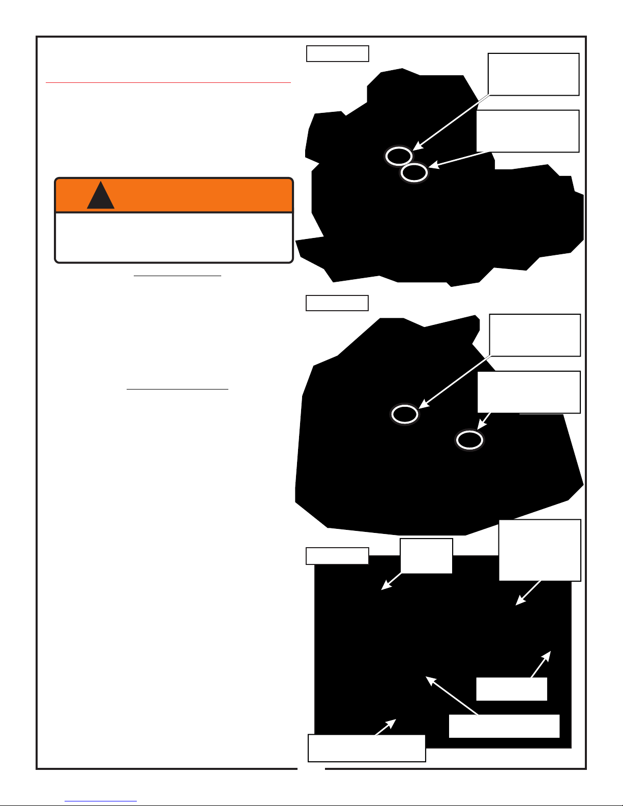
2-20 Safety Interlock Harness Installation
Collection System May Require Dealer Installation!
Before installing, please verify the presence of an auxiliary
5-way male connector in the mower’s electrical harness.
The connector is located underneath the operator’s seat,
in front of the battery. For early production LZ Models
without the connector, a dealer must perform the complete
collection system installation. If the connector is present,
or an early production SZ Model, dealer installation of the
collection system is not required.
WARNING
!
To Prevent Serious Injury-
Proper Installation Of Safety Interlock Harness
Is Mandatory. Please Check That All Interlock
Points Work Correctly Once Installed.
Dealer Installation
Figure 2-20a
LZ Model
Current Production
Model -
Connection Point
Early Production
Model -
Interconnection Point
Early Production LZ Models;
— Without auxiliary 5-way male connector.
— Interconnects between right steering lever plunger
switch & mower’s harness, located underneath
operator's seat. See Figure 2-20a.
— Dealer must disassemble the left & right pods along
with the seat box to make the electrical connection.
End-User Installation
Early Production SZ Models;
— Without auxiliary 5-way male connector.
— Interconnects between plunger switch & mower’s
harness, located underneath front left corner of floor
panel, near the brake. See Figure 2-20b.
— Connection point requires additional harness length to
make connection. Please disconnect standard harness
P#(P0209) from Left PTO Mount Assembly
P#(A1991) and attach Harness Extension
P#(P0263) in-between. See Figure 2-20c.
Current Production LZ & SZ Models;
— Auxiliary 5-way male connector present
— Connects to mower’s harness, located underneath
operator's seat, in front of battery. See Figure 2-20a &
2-20b.
Figure 2-20b
Figure 2-20c
SZ Model
P0208 Interlock
Harness
Current Production
Model -
Connection Point
Early Production
Model -
Interconnection Point
P0263 - Harness
Extension (Only
Used On Early
Production SZ
Models)
Harness Routing & Connecting;
— First, route the Safety Interlock Harness (w/ Extension,
if applicable) along the mower to the connection point.
See Figure 2-20c. When choosing a path for the
harness, make sure it will not contact moving parts or
high heat components. Next, remove any slack from
the harness, loop and fasten the excess using (1) ziptie P#(J0245). Then, secure the harness to the mower
frame with the remaining (6) zip ties. Last, check
harness operation only after complete collection
system is installed. With the mower running, deck PTO
off, and not sitting in the operator’s seat, engage the
PTO. If correctly installed, the mower should turn off. If
the mower does not turn off, check the steps above
and each connection point.
P0209 -
Plunger Switch
Connects/Interconnects
To Mower’s Harness
Connects To
Mower’s Plunger Switch
16
Page 17

P0208
Safety Interlock
Wiring Harness
17
Page 18

2-21 Impeller Blade
Removal/Replacement
WARNING
!
STEP 4: Remove the blade assembly and key
P#(J0254) from the PTO shaft.
Note: If necessary, use a break-free agent to aid in the
removal of the blade.
BEFORE REMOVING/REPLACING THE IMPELLER
BLADES, BE SURE THE MOWER IS TURNED OFF,
THE PTO ASSEMBLY IS DISENGAGED AND THE
NEGATIVE CABLE IS REMOVED FROM THE
BATTERY. FAILURE TO DO SO MAY RESULT IN
SEVERE INJURY OR DEATH.
REMOVAL
STEP 1: Remove the blower cone P#(V0016) from the
blower housing located on the PTO assembly
P#(A1878). With the blower cone removed, you will have
access to the impeller blade assembly P#(A1839). Refer
to Figure 2-21.
STEP 2: Remove the 5/16”-24 LH x 1-1/4” hex bolt
P#(K1171) and washer P#(K1446).
STEP 3: Insert the 1/2”-13 x 1” hex bolt (K1231) into the
threads on the blade assembly and tighten. The blade
should break free from the shaft.
Key
P#(J0254)
INSTALLATION
STEP 1: Insert the key P#(J0254) into the key way on
the PTO shaft.
STEP 2: Insert the blade assembly P#(A1839) onto the
PTO shaft.
STEP 3: Secure the blade assembly to the PTO shaft
with (1) washer P#(K1446) and (1) 5/16”-24 LH x 1-1/4”
hex bolt. Torque the bolt to 19 ft./lbs.
Blower Housing
P#(V0016)
Impeller Blade
Assembly P#(A1839)
Washer
P#(K1446)
5/16”-24 LH x 1-1/4”
Hex Bolt P#(K1171)
PTO Shaft
18
Page 19

19
Page 20

17
16
9
3
3
5
5
7
7
8
8
8
8
8
8
8
8
8
8
8
4
4
6
6
11
14
13
15
15
12
10
1
2
A2110 Top Assembly
Item # Part # Desc. Qty.
1 V2000 Pro 2 Bagger Top / Gen. 2 1
2 V2001 Screen 1
3 J4009 Short Rubber Strap w/ S-Hook 2
4 K1030 1/4"-20 x 1-1/4" Carriage Bolt 2
5 K0037 Flat Washer / 1/4" (.75 OD x .312 ID x .060 T) 2
6 K1128 1/4"-20 Nyloc Nut 2
7 K0062 3/16" x 1-1/2" Fender Washer, Z 2
8 K0114 Black Plastic Rivet 11
9 C0067 Dust Guard Mnt. Brkt. 1
10 V1117 Dust Guard 1
11 R0022 Decal / Built In The USA / Lg 1
12 R1069 Decal / Warning - Turn Off Blower 1
13 R1054 Decal / Important Check Hoses 1
14 R1051 Decal / Warning - Use Hearing Protection 1
15 R1057 Decal / 2" x 4" Red Reflector 2
16 C0026 Grass Deflector 1
17 B0676 Hinge Stop Pl. 1
Exploded Parts View
20
Page 21

PTO Assembly Exploded Parts View
A0429 - Gearbox
Assembly
A1842 - PTO
Assembly
A1004 - PTO Shaft
Assembly
21
Page 22

PTO Assembly Exploded Parts View Description
Item # Part # Description Qty.
43 A0431 Gear Box 1
44 A0498 Pulley Assy. / Gear Box 2
45 K0360 Snap Ring / 7/8" Shaft 2
46 J0272 Woodruff Key / #9 2
47 K0035 Set Screw / 5/16"-18 2
Item # Part # Description Qty.
39 E0015 Housing / PTO Shaft 1
40 N0147 Bearing (2.0472 OD, 0.9843 ID, 0.5906 W ) 1
41 B0460 PTO Shaft 1
42 N0165 Bearing 1
Item # Part # Desc. Qty.
1 M0266 A-Section Pulley 1
2 K1446 W asher (1.187 OD x .380 ID x .187 T) 2
3 K1190 HHCS / 3/8"-16 x 3/4" 1
4 V0015 Blower Hsg. 1
5 A0429 Gear Box Assy. 1
6 A1004 PTO Shaft Assy. 1
7 A1003 PTO Base Plate Assy. 1
8 B0681 Pulley Guard / Gear Box Assy. 1
9 K1153 HHCS / 5/16"-18 x 3/4" 4
10 K1178 Flange Nut / 5/16"-18 4
11 K1191 HHCS / 3/8"-16 x 1" / G5 2
12 K1215 Flange Nut / 3/8"-16 6
13 K0037 Flat Washer / 1/4" (.75 OD x .312 ID x .060 T) 4
14 K1150 HHCS / 1/4"-20 x 2-1/4" 2
15 K1126 Flange Nut / 1/4"-20 4
16 K1202 HHCS / 3/8"-16 x 4-1/2" / G5 2
17 K1216 Nyloc Nut / 3/8"-16 2
18 K0348 HHCS / 3/8"-16 x 2" All Thread 1
19 K0042 Flat Washer / 5/16" (.875 OD x .380 ID x .075 T) 5
20 K0353 HHSTS / 1/4"-20 x 1/2" 3
21 J0303 Spring 2
22 K1192 HHCS / 3/8"-16 x 1-1/4" 4
23 M0267 Kevlar Belt / A28K 1
24 V1151 Black Handle Grip (5/8" ID x 4-3/4" L) 1
25 K0048 Lock Washer / 3/8" 1
26 B0505 Mount Rod / PTO Arm 1
27 B0506 Lt. PTO Arm 1
28 B0642 Mount Bracket / Blower Hsg. 1
29 B0643 Rt. PTO Arm 1
30 A1137 PTO Handle Assy. 1
31 B0510 Spacer Bushing / Small 1
32 B0511 Spacer Bushing / Large 1
33 K0403 Flat Washer (1-1/2" OD x 3/8" ID x .092 T) 3
34 B0739 Stiffener Plate / Blower Hsg. 1
35 K0070 Flat Washer (1.295 OD x .881 ID x .020 T) 1
36 A1839 3-Blade Impeller Assy. 1
37 J0254 Key / 3/16" x 3/16" x 3/4" 1
38 K1171 HHCS / 5/16"-24 LH x 1-1/4" / G5 w/ Patch Coating 1
A1842 - PTO
Assembly
A1004 - PTO Shaft
Assembly
A0429 - Gearbox
Assembly
22
Page 23

SAFETY DECALS
To promote safe operation, New PECO, Inc. supplies safety decals on all products manufactured. Damage can occur to
safety decals either through shipment, use or reconditioning. Contact your local Service Center for replacement decals.
Part# R0023
Cub Cadet
DANGERDANGERDANGER
!
TO CLEAR D EBRIS WI TH BLOWER
PELIGROPELIGROPELIGRO
!
PARA LI NPIAR BASURA CON LA
R2007R2007R2007
HOJA EN MA RCHA!
NEVER US E HANDS
RUNN ING!
NUNCA US E MANOS
Logo
DANGERDANGERDANGER
!
FINGERS, HANDS, & BODY PARTS
PELIGROPELIGROPELIGRO
!
DEDOS, MA NOS Y PARTES D EL
CUERPO P UEDAN SER CORTAD OS!
R2008R2008R2008
ROTATING BLADES!
CAN BE SE VERED!
HOJA ROTANTE!
Part #: R2007
Never Use Hands Label
PUSH HANDLE
DISENGAGEDISENGAGEDISENGAGE
PULL HANDLE
ENGAGEENGAGEENGAGE
Part #: R1100
Engage-Disengage Label
Part #: R1054
Important Label
R1100
Part #: R4037
Warning: Hot Surface Label
Part #: R1065
Made In America Label
MADE INMADE IN
MADE IN
AMERICAAMERICA
AMERICA
Part #: R2008
Rotating Blades Label
Part #: R1052
Small Warning: Turn Off Blower Label
Part # R0024
Danger Keep Hands
Clear
Part #: R1057 - (2)
Part #: R1051
Warning: Hearing Protection Label
23
Part #: R1069
Warning: Turn Off Blower Label
Part # R0025
Danger Rotating
Blades
Page 24

SECTION III
3-3 Disengagement Of The PTO Assy.
OPERATING INSTRUCTIONS
3-1 General Safety
Only qualified people familiar with this operator’s manual
and the mower’s operator’s manual should operate this
machine.
3-2 Operation And Tips On Mowing
A. Perform BEFORE EACH USE the maintenance list
in paragraph 4-1.
B. Start mower.
C. With the mower at high idle speed, engage the mower
deck.
D. While seated in the operator’s seat, pull the
engagement handle of the PTO assembly towards
the operator’s seat until the handle slides into
position in the retaining slot. With the PTO assembly
engaged, you can proceed to operate the control
levers of the mower.
NOTE: If the collection system does not appear to be
collecting the grass clippings, disengage the deck
and PTO assembly, then, engage the parking brake
and turn the mower off. Proceed to section 3-3, and
review the sections regarding PTO assembly
Installation and belt installation/removal and
adjustment. Check upper and lower hoses for any
clogs.
To obtain the maximum effectiveness from your
collection system the tips listed below should be
followed:
* Watch your speed- Normal conditions will allow a
speed of up to approximately 5 mph, but thick, heavy
damp conditions will require reduced ground speed.
* Mow with sharp blades- A sharp blade cuts cleaner.
A. To disengage the PTO assembly, slide the
engagement handle out of the retaining slot and push
the engagement handle away from the operator’s
seat.
WARNING: The PTO assembly blades will continue to
spin. DO NOT TOUCH the PTO assembly, pulleys,
or the belt until the tractor is turned off. DO NOT
adjust the belt tension until the mower is turned off.
Refer to the belt adjustment section of the manual.
3-4 Unloading The Collection System
NOTE: To determine when the collection bags are full,
follow the following steps:
A. Stop the forward movement of the mower.
B. Disengage the mower deck.
C. Disengage the blower.
D. Engage the parking brake.
E. Once the parking brake has been engaged, then and
only then, walk behind the mower and check the
collection bags by first unhooking the rubber strap
with S-hook that secures the plastic top, then lift the
plastic hood. Load in bags should not exceed the
height of the installed bag.
F. To remove the bags from the frame slide bags out and
turn bags over to deposit clippings.
G. Slide empty bags back onto the frame and secure
plastic top with the rubber strap with S-hook.
NOTE: Do not allow collection bags to become over-
filled as potential damage may occur to your
equipment. Also, be sure to clean the hood screen as
needed.
SECTION I - MAINTENANCE
* Wet grass and leaves will decrease effectiveness and
will increase horsepower requirements.
* Mow at higher cutting heights- Remove and mulch no
more than 2” of grass length with each mowing.
(Experts recommend not cutting off more than 1/3 of
the grass blade length at any given time.)
* Mow twice, at different height settings, (high, then low),
if grass is extra tall.
* Remember that horsepower requirements will vary with
the mowing conditions such as type and height of turf
grass, moisture content, amount of leaves, whether the
terrain is flat or hilly, etc.
4-1 Maintenance Checklist
NOTE: REMOVE PTO ASSEMBLY BEFORE
RAISING DECK FOR MAINTENANCE.
Before each use:
1. Check blades and spindles to be sure that no foreign
objects, such as wire or steel strapping bands, are
wrapped around them.
2. Inspect blades for wear. Replace if necessary. If it is
necessary to sharpen the blades, remove the blades
from the spindles before sharpening. DO NOT
sharpen blades while still attached to the mower.
24
Page 25

3. Make sure all shields are in place and in good
condition. Repair or replace any missing or damaged
shields.
4. Perform lubrication per paragraph 4-2.
5. Listen for abnormal sounds, which might indicate
loose parts, damaged bearings, or other damage.
Correct any deficiency before continuing operation.
6. With the engine off, engage the blower assembly.
Check the belt tension and inspect the pulley belt for
cracks or tears.
4-2 Lubrication
Gearbox:
1. Every 20 hours of use: Check oil levels in gearbox.
2. First 60 hours of use: Change oil.
3. Every 100 hours of use: Change oil.
NOTE: Oil in gearbox should cover the gears. If not,
drain the gearbox and fill using an 80W-90 gear oil.
The gearbox ships with 6.0 oz. of oil, but we
recommend replacing with a measured 5.5 oz. to fill
the gearbox. DO NOT OVERFILL!
7. Check for wear or deterioration of the upper or lower
hoses. If there are any portions of the hose that have
been torn or worn through, replace immediately.
After Each Use:
1. Clean all debris from machine especially from the
container, underneath the belt shields, and safety
decals. Replace any missing or illegible decals.
2. Inspect the unit for worn or damaged components.
Repair or replace before the next use. Any
replacement component installed during repair shall
include the component’s current safety decal specified
by the manufacturers to be affixed to the component.
3. Under normal usage, the bag material is subject to
deterioration and wear and should therefore be
frequently checked for necessary replacement. Any
replacement bag should be checked to ensure
compliance with the original manufacturer’s
recommendations or specifications.
4. Check belt for proper tension.
Blower Assembly:
NOTE: The following is for older PTO models that
contain a greaseable zirc fitting. Newer models
contain maintenance-free bearings and are without
a greasable fitting.
.
1. On initial use: Grease the fitting on the blower shaft.
2. Every 25 hours of use: Re-grease the grease fitting.
NOTE: Use only white lithium based grease for
lubrication of the shaft on the blower assembly.
SECTION V - PARTS & SERVICE
5-1 Parts And Service Information
Collection system owners should record the name and
telephone number of their Service Center. Your Service
Center will be happy to supply replacement parts,
accessories, and do any service or repairs to your
collection system. If for any reason your Service Center
is unable to service your collection system or supply
replacement parts, contact New PECO, Inc. and include
the following information on the chart below.
DOCUMENT THE FOLLOWING INFORMATION FOR FUTURE REFERENCE
Unit Model Number:_______________________________________________
Unit Engine Size:__________________________________________________
Unit Serial Number:________________________________________________
Date of purchase:________/________/_________
Dealer/Distributor Name:__________________________________________
Address: _________________________________ State:_______ Zip:_______
Phone Number: ____________________________________________________
THE SERIAL NUMBER PLATE
IS LOCATED ON THE TOP
ASSEMBLY
25
Page 26

26
Page 27

Notes
27
Page 28

MTD Products Limited
Cub Cadet LLC
P.O. Box 361131
Cleveland, Ohio 44136-0019
Phone: 1-877-282-8684
Kitchener, ON N2G 4J1
1-800-668-1238
 Loading...