

Page 1
Hydrostatic Zero-Turn
Commercial Riding Mower
Professional Turf Equipment
54" Fabricated Deck
ILLUSTRATED PARTS LIST
Page 2

TABLE OF CONTENTS
Frame Assembly. . . . . . . . . . . . . . . . . . . . . . . . . . . . . . . . . . 3
54" Fabricated Cutter Deck. . . . . . . . . . . . . . . . . . . . . 4 and 5
54" Spindle Assembly. . . . . . . . . . . . . . . . . . . . . . . . . 6 and 7
Hydro Pump Assembly . . . . . . . . . . . . . . . . . . . . . . . . . . . . . 8
Brake Motor Mount and Hub. . . . . . . . . . . . . . . . . . . . . . . . . 9
Brake Assembly . . . . . . . . . . . . . . . . . . . . . . . . . . . 10 and 11
Fuel Tank Assembly . . . . . . . . . . . . . . . . . . . . . . . . . . . . . . 12
Rear Bumper . . . . . . . . . . . . . . . . . . . . . . . . . . . . . . . . . . . 13
Front Caster Assembly . . . . . . . . . . . . . . . . . . . . . . . . . . . . 14
Control Assembly . . . . . . . . . . . . . . . . . . . . . . . . . . 16 and 17
54" Wheel Assembly. . . . . . . . . . . . . . . . . . . . . . . . . . . . . . 18
Drive Assembly. . . . . . . . . . . . . . . . . . . . . . . . . . . . . . . . . . 19
23HP Kawasaki Engine Assembly . . . . . . . . . . . . . 20 and 21
24HP Honda Engine Assembly . . . . . . . . . . . . . . . 22 and 23
25HP Kohler Engine Assembly. . . . . . . . . . . . . . . . 24 and 25
23HP Electrical Assembly Kawasaki . . . . . . . . . . . . . . . . . 26
Electrical Assembly Kohler/Honda . . . . . . . . . . . . . . . . . . . 27
Seat Assembly . . . . . . . . . . . . . . . . . . . . . . . . . . . . . . . . . . 28
Foot Pedal Assembly . . . . . . . . . . . . . . . . . . . . . . . . . . . . . 29
Lift Assembly . . . . . . . . . . . . . . . . . . . . . . . . . . . . . 30 and 31
Floor Panel Assembly. . . . . . . . . . . . . . . . . . . . . . . . . . . . . 32
MODELS LISTED IN THIS MANUAL
23HP Tank, 25HP Tank,
53CB5DBW750 53BB5B8W750
24HP Tank,
53CB5ETW750
2
Page 3
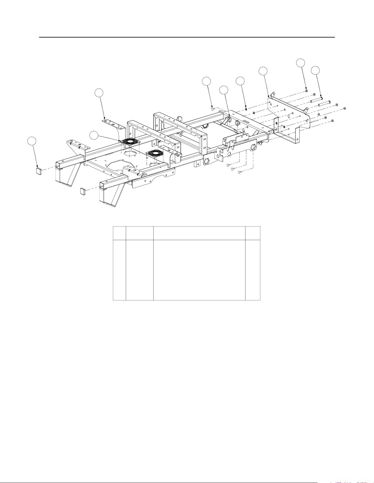
Frame Assembly- Figure 1 and Parts List
2
8
1
3
7
5
4
6
9
GD: 02000020-10/20/04
Ref.
No. Part No. Description Qty.
1 00022560 Hex Nut, 3/8-16 Flange Lock 7
2 01000372 Carriage Bolt, 3/8-16 x .75 Long 7
3 01001713 Bracket Assembly, Frame, Front 1
4 01003282 Clevis Pin, .625 Dia x 4.375 Long 2
5 01003993 Linch Pin, 3/16 Dia. 2
6 01005160 Plug, Square Tube 2
7 01008225 Push Retainer, 3/8 4
8 02000019 Frame Assembly 1
9 02000129 Cover, Hydro Fan 2
3
Page 4
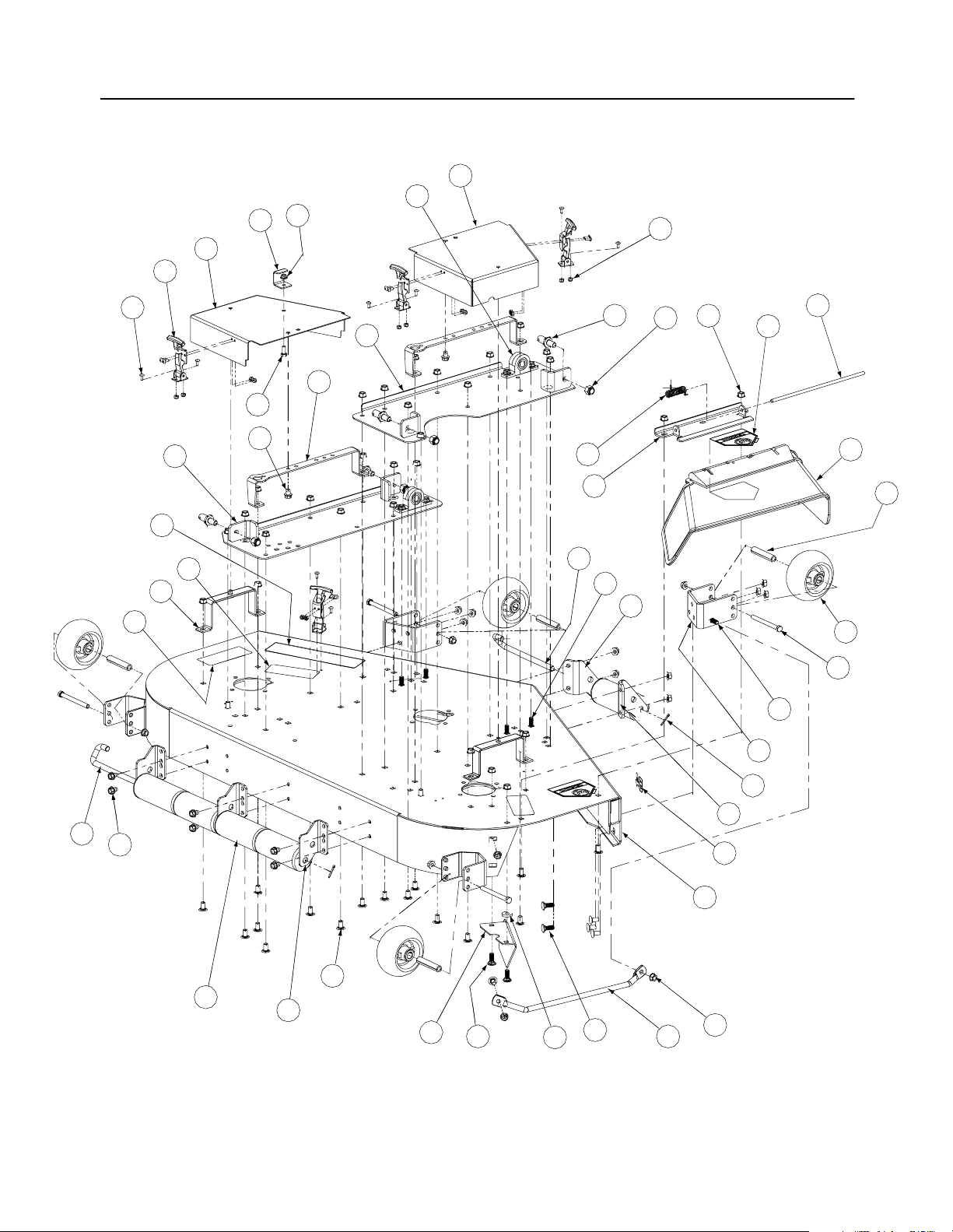
54" Fabricated Deck Assembly - Figure 2
37
44
16
22
38
39
42
41
33
26
5
23
27
43
8
34
7
18
19
36
13
3
31
6
4
20
30
9
35
15
11
2
17
1
32
21
23
14
29
12
24
17
10
17
25
40
28
6
GD: 01008835-01/06/05
4
Page 5

54" Fabricated Deck Assembly - Parts List for Figure 2
Ref.
No. Part No. Description Qty.
1 00003107 Cotter Pin, .125 Dia x 1.0 2
2 00011925 Hex Cap Screw, 3/8-16, 3.75 4
3 01002010 Carriage Screw, 3/8-16 x 1.25 4
4 00012428 Lock Nut, Nylon Insert, 1/2-13 4
5 00013406 Hex Cap Screw, 5/16-18 x 3/4 1
6 00022560 Hex Nut, 3/8-16 Flange Lock 50
7 00030633 Decal Rotating Blade 1
8 00030635 Decal, Warning Shield Missing 2
9 01003254 Defllector Chute Rod 1
10 00083192 Idler Washer 1
11 01000343 Complete Wheel, 5.00 Dia. 4
12 01000372 Carriage Bolt, 3/8-16 x .75 Lg. 38
13 01000375 Roller Pin. 1/2 Dia. x 7.31 Lg. 1
14 01000385 Front Roller 5
15 01000398 Wheel Spacer 4
16 01000635 Hexflange Lock Nut, 5/16-18 1
17 01000643 Carriage Bolt, 3/8-16 x 1 7
18 01001745 Pin, 5/8 Dia. x 1.2 Lg. 4
19 01003253 Spring Torsion, 0.4 ID x 2.16 LG 1
20 01002166 Decal, Danger Hands and Feet 2
21 01002635 Roller Pin 1
22 01004109 Tension Rod Stop Bracket 1
23 01004304 Hex Index Washer Screw, 3/8-16, .5 8
24 01009300 Chute Bracket 1
25 01008644 Finger Guard 1
26 01004685 Cover Support 2
27 01008633 Left Hand Mount, Deck Bracket Assembly 1
28 01008813 54 Deck Assembly 1
29 01005364 Roller Mount Bracket 3
30 01005260 Anti-Scalp Wheel, Front Mount Bracket 2
31 01005256 Left Hand Front Roller Mount Bracket 1
32 01005258 Right Hand Front Roller Mount Bracket 1
33 01008635 Deck Bracket Assembly 1
34 01005437 Outer Belt Cover Support Assembly 2
35 01006693 Deflector Chute 1
36 01008226 Deflector Chute Bracket 1
37 02000446 Right Hand Belt Deck Cover 1
38 02000445 Left Hand Belt Deck Cover 1
39 01005869 T-Handle Draw Latch 4
40 01002129 Decal, 54" 2
41 00017778 Phillips Head Screw, 10-32 16
42 00014608 Lock Nut, Nylon Insert, 10-32 16
43 01006086 Mower Deck Label 1
44 02000109 Pillow Block 2
5
Page 6
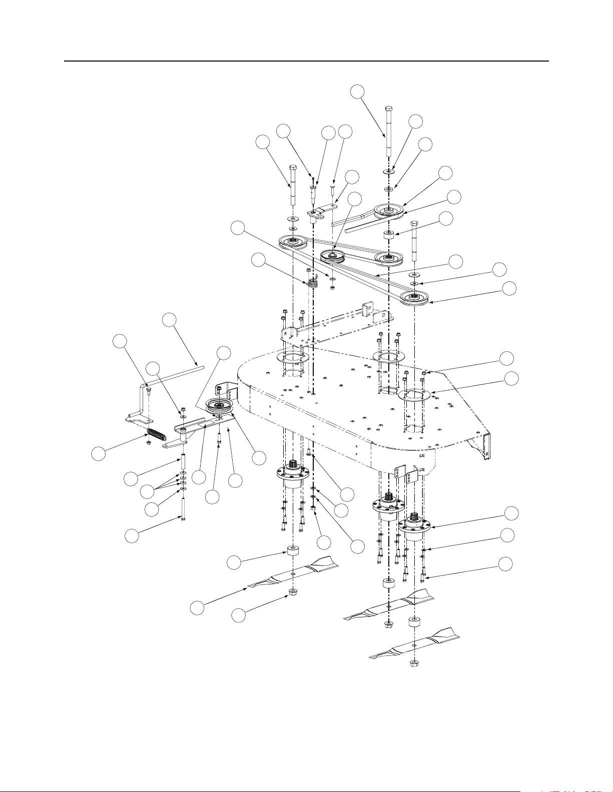
54" Fabricated Deck Spindle Assembly - Figure 3
35
6
31
17
13
37
26
17
17
10
9
20
24
14
18
30
34
27
33
11
36
5
28
8
19
7
17
3
23
2
32
25
29
16
15
22
27
12
1
21
4
2
GD: 01004277-10/21/04
6
Page 7

54" Fabricated Deck Spindle Assembly
Ref.
No. Part No. Description Qty.
1 01000389 Lock Washer, 7/16 1
2 00008495 Hex Cap Screw, 3/8-16 x 1-1/4 13
3 00011925 Hex Cap Screw, 3/8-16, 4.00 1
4 00012158 Flat Washer, 3/8 12
5 00022560 Hex Nut, Flange Lock, 3/8-16 17
6 00060078 Grease Fitting, 1/4-28 x 3/16 1
7 00083192 Idler Washer 3
8 01000199 Extension Spring, 1.0 OD x 5.125 1
9 01000302 Shoulder Screw, 7/16-14 1
10 01000364 Hex Carriage Screw, 3/8-16, 1.75 1
11 01003123 Spacer, .812 ID x .218 LG 2
12 01000380 Flange Hex Nut, 3/4-16 3
13 01000387 Torsion Spring Idler 1
14 01000392 Flat Washer, .781 ID, 2.00 OD, .105 3
15 01000393 Flat Washer, .469 ID, .875 OD, .105 1
16 01000643 Carriage Bolt, 3/8-16 x 1 1
17 01000723 Flat Washer, .406 ID, 1.0 OD, .105 4
18 00021925 Spacer 1
19 01003245 Spacer, .39 ID x .625 OD x 2.75 1
20 01005737 Idler Arm Assembly, Deck Spindle Includes: 1
01000308 Bearing 2
21 01003532 Spindle Assembly, Aluminum Fab Deck 3
22 00005763 Hex Nut, 7/16-14 1
23 01006382 Decal, Idler Location 1
24 01004081 Flat Pulley 1
25 01004101 Idler Pulley, 4.06 OD w/Deep Plan Flanges 1
26 01004118 Shoulder Screw, .50 x .27 LG, 3/8-16 1
27 01004415 Spacer, .760 ID x 2.000 OD x 1.1 4
28 01005434 Plate Support, Cast Aluminum Spindle 3
29 01006181 Idler Arm Assembly, Flat Top Bearing 1
30 01005201 V Pulley, 5.25 OD 1
31 01005213 Hex Cap Screw, 3/4-16, 7.00 2
32 01005337 Hi-Lift Blade, 19.0, 0.756 3
33 01005375 V Belt, A Section x 114.3 1
34 01005378 V Belt, B Section x 87.3 1
35 01005388 Hex Cap Screw, 3/4-16, 9.00 1
36 01005616 V Pulley, 5.00 OD 3
37 01005690 Rod Fab Deck Spring Tension 1
- Parts List for Figure 3
7
Page 8
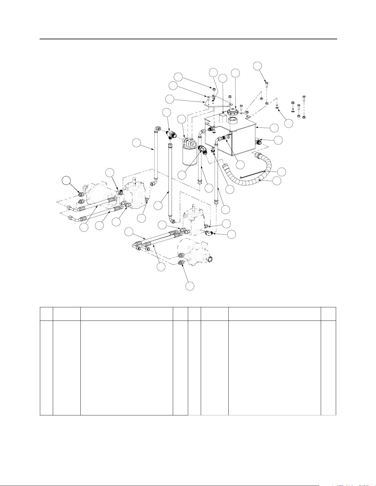
Hydro Pump Assembly - Figure 4 and Parts List
27
14
7
5
6
10
8
9
1
11
12
26
18
22
25
21
22
3
13
21
22
17
3
Ref.
No. Part No. Description Qty.
20
24
2
15
23
13
18
Ref.
No. Part No. Description Qty.
19
4
16
GD: 01006935-12/03/04
1 00006144 Hex Cap Screw, 3/8-16, 1 4 14 01001650 Oil Filter Mounting Plate 1
2 00012288 Fitting 1/2 x 3/4 - O Ring 4 15 01004192 Oil Pan Drain w/ Seal and Plug 1
3 00012426 Fitting 1/2 x 3/4 - O Ring to Flare 4 16 01004268 Tank to Filter Hose Assembly 1
4 00012470 Cable Tie, 3/16 x .05 x 7.4 5 17 01004272 Connector, 3/4 x3/4 1
5 00013131 Hex Cap Screw, 1/4-20, .75 2 18 01004542 Elbow Fitting, 3/8 O-ring, 1/2 Flare 2
6 00017665 Filter Head 3/4 includes: 1 19 01004702 Fitting Elbow, 1/2 x 1/2 1
01004166 Filter 20 01006353 Fitting, 3/8 NPT, 1/2 Flare 2
7 00022560 Hex Nut Flange Lock, 3/8-16 8 21 01006874 Long Pressure Hose Assembly 2
8 00030261 Cap, Hydro Oil Tank 1 22 01006893 Short Pressure Hose Assembly 2
9 00031994 Decal Oil Only 20W50 1 23 01006901 17.75" Return Hose Assembly, RH 1
10 00012132 Lock Washer, 1/4 1 24 01006902 14" Return Hose Assembly, LH 1
11 01000372 Carriage Bolt, 3/8-16 x .75 LG. 2 25 01006914 21.25" Supply Hose Assembly, RH 1
12 01004516 Hydraulic Tank Assembly 1 26 01006916 15.50" SupplyHose Assembly, LH 1
13 01002606 Fitting Connector, 1/2 x 3/8 2 27 01006959 Tee Fitting, 3/4 x 1/2 x 1/2 1
NOTE: Lubricant, 737-3120 Gallons, 3.25
8
Page 9
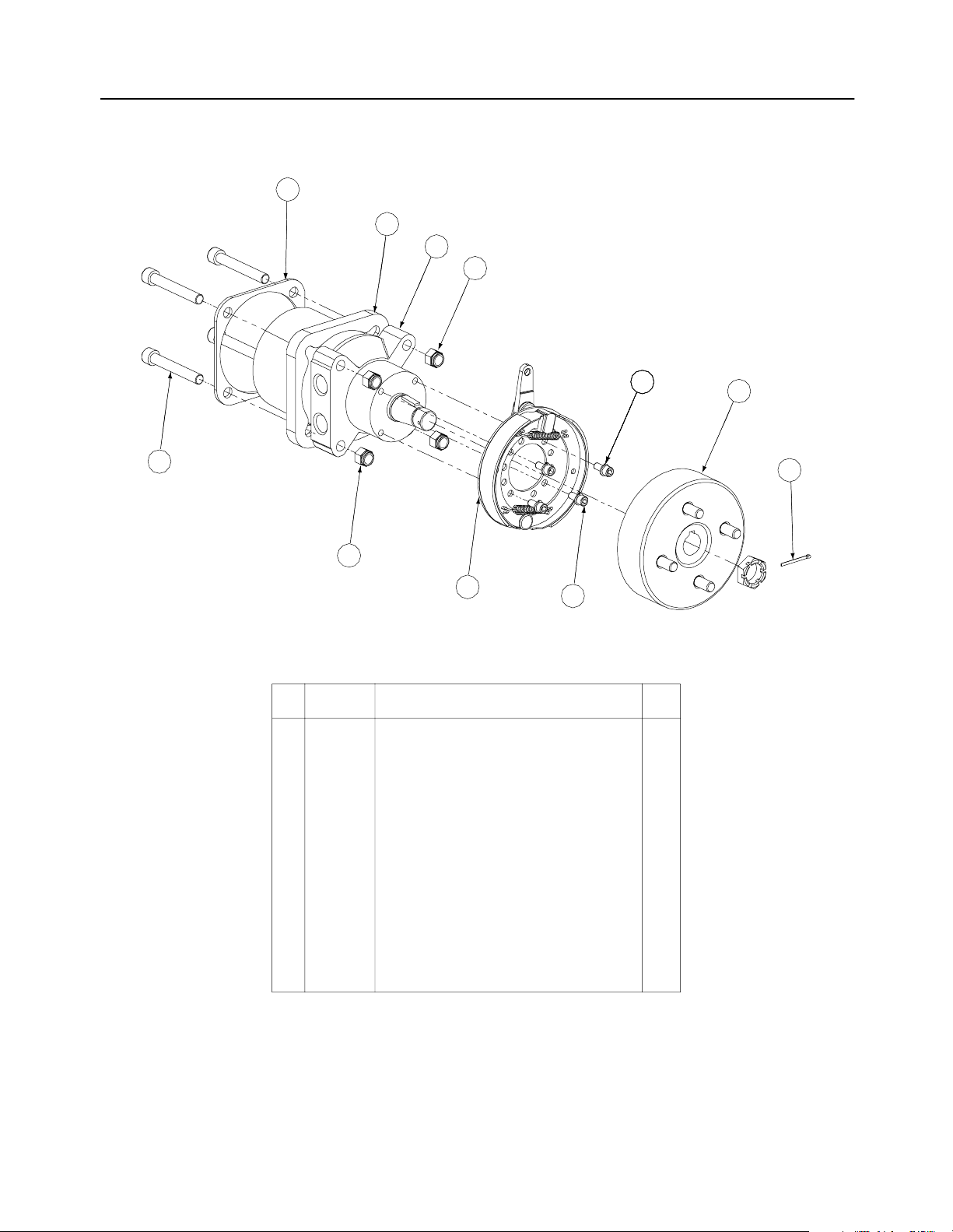
Brake Motor Mount and Hub- Figure 5 and Parts List
2
3
6
1
7
4
1
8
Ref.
No. Part No. Description Qty.
1 00012428 Lock Nut, Nylon Insert, 1/2-13 8
2 01006948 Motor Plate 2
3 01009775 Motor Spacer 2
4 01007791 Socket Head Capscrew, 1/2-13; 3-1/2 8
-- 01000226 Capscrew, 1/2-13 x 3.5 8
5 -- Hyd. Motor, Parker Left Hand Assembly w/
Brake & Drum (Not Shown)
-- 01006730 Hyd. Motor, Parker Left Hand 1
6 -- Hyd. Motor, Parker Right Hand Assembly
w/ Brake & Drum
-- 01006953 Hydro Motor, Parker Right Hand 1
7 00012168 Lock Washer, 5/16 8
8 01007048 Brake Assembly w/Line 2
9 01007049 Hub and Drum Assembly w/Studs 2
10 01007464 Capscrew w/Socket, 5/16-18 x 3/4 8
11 01007773 Cotter Pin 1/8 x 1-1/2 2
10
1
1
9
11
GD: 01008450-12/14/04
9
Page 10
Brake Assembly - Figure 6
21
12
14
16
17
6
25
8
23
22
16
13
26
15
24
11
5
18
16
12
3
9
28
29
1
30
10
12
19
10
7
2
20
4
27
10
31
GD: 02000010-12/02/04
Page 11

Brake Assembly
- Parts List for Figure 6
Ref.
No. Part No. Description Qty.
1 741_0598 Hex Flange Bearing, .752 ID 2
2 00011459 Washer, 1/2 2
3 00012152 Lock Nut, Nylon Insert, 1/4-20 1
4 00012382 Hex Cap Screw, 5/16-18 x 1-1/2 2
5 00013092 Hex Cap Screw, 5/16-18 x 1.0 1
6 00022560 Flange Lock Hex Nut, 3/8-16 1
7 00027279 Nut, 7/16-14, Nylock 2
8 00071691 Spacer, Control Rod 1
9 01000371 Hex Cap Screw, 3/8-16 x 3-1/4 1
10 01000393 Flat Washer, .469 ID, .875 OD , .105 4
11 01000629 Screw, TT, 1/4-20, 0.75, Hex Index Washer 1
12 01000635 Nut, Lock, HexFlange, 5/16-18 4
13 01000723 Flat Washer, .406 ID x 1.0 OD x .105 1
14 01000897 Screw, TT, 1/4-20, 1.0, Hex Index Washer 1
15 01002751 Spacer, .39 x .63 x 1.75 1
16 01002771 Cotter Pin, .072 x 1.12 Lg 6
17 01003595 Brake Handle 1
18 01003468 Spacer, .375 x .50 x .75 Lg 1
19 01003574 Neutral Brake Spring 2
20 01003575 Force Brake Spring 2
21 01003716 Parking Brake Grip 1
22 01008600 Socket Head Capscrew, 5/16-18 x 1.50 1
23 01008607 Spacer, Pump Release 1
24 01008886 Brake Rod 1
25 01008889 Parking Brake Mounting Bracket 1
26 01009561 Brake Arm Assembly 1
27 01009566 Brake Arm Bracket 2
28 01009569 Pivot Brake Shaft 1
29 01009601 Hose, .5 ID x .78 OD, Low Pressure 2
30 01009602 Spacer, .76 ID x 1.0 OD x 3/4 2
31 02000015 Connector Rod Rod 2
11
Page 12

Fuel Tank Assembly - Figure 7 and Parts List
8
9
3
4
10
13
1111
12
7
2
1
6
5
Ref.
No. Part No. Description Qty.
1 01000723 Flat Washer, .406 ID, 1.0 OD, .105 8
2 -- Hose, 1/4" Fuel Line (in inches) 79.5
3 00012235 Clamp, Union 6
4 01000069 Fuel Cap, 3.5 2
5 01000368 Hex, Cap Screw, 3/8-16, .88 8
6 00012157 Lock Washer, 3/8 8
7 01007218 Fuel Tank 2
8 01007425 Fuel Fitting 2
9 01000281 Grommet, Fuel Tank 2
10 01003473 Tee Fitting, Fuel 1
11 00031081 Clamp, 1/2 Tubing 1
12 00012470 Cable Tie 2
13 01000600 Flat Washer, 1.4 x .630 x .0515 1
GD: 01007424-11/28/01
12
Page 13

Rear Bumper - Figure 8 and Parts List
3
4
6
1
2
5
Ref.
No. Part No. Description Qty.
1 00012428 Hex Nut, 1/2-13, Insert Lock 2
2 00022560 Nut, Hex 3/8-16 Flange Lock 2
3 00030046 HHCS, 1/2-13, 3.00 2
4 01003534 Carriage Bolt, 3/8-16 x 2.75 2
5 01009992 Bar, Weight 2
6 02000453 Rear Bumper Plate 1
GD: 02000180-10/21/04
13
Page 14

Front Caster Assembly - Figure 9
16
17
15
18
13
14
9
1
21
19
8
12
2
3
11
6
10
20
2
22
4
7
5
14
19
GD: 02000369-10/21/04
Page 15

Front Caster Assembly - Parts List for Figure 9
Ref.
No. Part No. Description Qty.
1 00023287 Nut, 1/2-20, Center Lock 2
2 01006294 Bell Washer, 1.25 ID x 2.5 x .157 2
3 00060078 Grease Fitting, 1/4-28 x 3/16 3
4 02000588 Flat Washer, 1.00 ID 2
5 02000589 Spacer, 1.005 ID x 1.25 OD x 3.6 1
6 01000678 Nut, Jam, 1.0-14, Insert Lock 1
7 01006309 Hex Cap Screw, 1-14 x 5.0 1
8 01006913 Wheel, 13 x 6.50 x 6, White includes: 2
01007564 Tire 13 x 6.50-6 SMTH 1
Flange Bearing 2
Cage Roller Bearing 2
9 01007407 Yoke, Caster Wheel 2
10 01006961 HHCS, 1/2-20, 7.50 2
11 02000439 Front Axle Assembly 1
12 01002620 Cup Bearing 4
13 01002621 Bearing Cone 4
14 01002622 Seal 2
15 01002624 Ring Seal 4
16 01006347 Grease Cap, 1.986 OD 2
17 01002626 Slotted Nut, 3/4-16 2
18 01002627 Cotter Pin, 5/32, 1.25 2
19 01006912 Wheel Spacer 2
20 01003123 Spacer, .812 ID x .218LG 4
21 01009997 Retainer Extension, Self Locking 1
15
Page 16

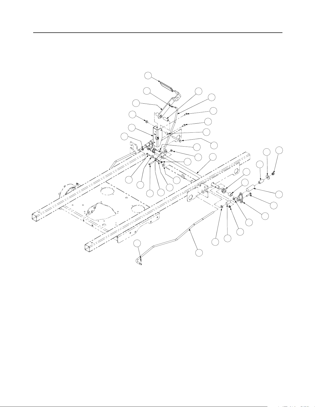
Control Assembly- Figure 10
44
24
9
26
8
33
48
18
13
28
30
42
6
7
3
2
14
27
43
50
14
34
17
9
10
11
20
9
8
21
8
4
40
32
10
5
37
14
38
36
46
1
23
19
39
45
12
35
22
29
9
16
29
25
15
41
31
47
49
16
GD: 02000030-10/20/04
Page 17

Control Assembly -
Parts List for Figure 10
Ref.
No. Part No. Description Qty.
1 00008495 Capscrew, 3/8-16 x 1-3/4 2 25 01003199 Stop, RH 1
2 00009812 Flat Washer, 5/16 4 26 01003200 Stop, LH 1
3 00011861 HHCS, 3/8-16, 2.25 4 27 01003451 Decal Right Hand Control 1
4 00012168 5/16, Lock Washer 2 28 01003452 Decal, Left Hand Control 1
5 00012226 Grease Fitting, 90° 2 29 01003561 Nut, Hex, Center Lock, M8 4
6 00013092 HHCS, 5/16-18 x 1.0 1 30 01003715 Grip, 1.0 2
7 00013406 Hex, Cap Screw, 5/16-18 x 3/4 4 31 01003947 U-Nut, 3/8-16, .75 2
8 00022560 Hex Nut, 3/8-16, Lock Flange 23 32 01004003 Flat Washer, 5/8 Nylon 4
9 01000372 Carriage Bolt, 3/8-16 x .75 15 33 01004127 HHCS, 3/8-16, 3.00 2
10 01000450 Hex Jam Nut, 3/8-24 4 34 01005851 External Washer, 3/8 2
11 01000451 B/Joint, 3/8-24, Right Hand Female 2 35 01004890 Control Panel, RH 1
12 01000628 Screw, TT, 1/4-20, 0.5, Hex Index Washer 11 36 01006350 Shaft Collar 2
13 01000629 Screw, TT, 1/4-20, 0.75, Hex Index Washer 1 37 01007312 Spacer, .385ID x .625 OD x .50 Lg 2
14 01000635 Nut, Lock, HexFlange, 5/16-18 7 38 01007734 Turnbuckle 2
15 01000643 Carriage Bolt, 3/8-16 x 1 2 39 01008367 B/Joint, 3/8-24, Left Hand Female 2
16 01000960 Belle Washer, .325 x .930 x .045 2 40 01008518 Rod Connector 3/8 OD x 14.25 2
17 01001727 Cylinder Return to Neutral 2 41 01010190 Lapbar, Handle Assembly 2
18 01002511 Nut, 3/8-16, Jam 2 42 01010176 Mounting Handle 2
19 01002986 Nut, 3/8-24, Jam, LH Third 2 43 02000164 Switch Mounting Bracket, Lapbar 2
20 01002988 Screw, Shoulder Control Rod 2 44 02000162 Decal, Left Hand Console 1
21 01003044 Hub Assy, Control LH Bearing 1 45 02000163 Decal , Right Hand Console 1
01004265 Bearings 2 46 02000175 Shaft Control Brake Steering 1
22 01003011 Lever, Safety Switch 2 47 02000178 Side Panel, Control, Right 1
23 01003045 Hub Assy, Control RH Bearing 1 48 02000179 Side Panel, Control, Left 1
01004265 Bearings 2 49 02000340 Cup Holder Assembly 1
24 01004889 Control Panel, LH 1 50 01000443 Screw Button Head, 1/4-20 x .5 1
Ref.
No. Part No. Description Qty.
17
Page 18

54" Wheel Assembly - Figure 11 and Parts List
2
1
Ref.
No. Part No. Description Qty.
1 00012187 Lug Nut, 1/2-20 8
2 01002182 Wheel Assembly, 24 x 12-8, Dr,
White: Includes
01004473 Tire, Turf Saver, 24 x 12.00-12, 2-Ply
Rim, 12 Dia x 8.50 width, 4x4 Bolt
OPTIONAL TIRES
01006324 Turf Master, Rear Wheel Assembly
2
GD: 01002572-09/27/00
18
Page 19

Drive Assembly- Figure 12 and Parts List
17
9
4
12
14
5
18
10
1
8
5
6
7
13
15
16
2
3
5
5
7
8
8
5
11
6
GD: 01006918-01/12/05
Ref.
No. Part No. Description Qty.
Ref.
No. Part No. Description Qty.
1 00012157 Washer lock 3/8 zinc 2 10 01002010 Carriage Screw, 3/8-16 x 1.25 4
2 00012152 Lock Nut, Nylon Insert, 1/4-20 2 11 01001618 Strut Frame 2
3 00019962 Socket Head Cap Screw, 1/4-20 x 2-1/2 2 12 01005339 Hydro Pulley Fan 2
4 00020628 Key, 3/16" x 7/8" 2 13 01006728 Hydro Motor Frame Assembly 1
5 00022560 Flange Lock Hex Nut, 3/8-16 20 14 01006799 Hydro Pulley Pump 2
6 01000369 Hex Cap Screw, 2/8 -16 x 1.25 1 15 01006936 Hydro Pump, LH 1
7 750-3119 Spacer, .406 ID x 1.00 OD x .38 1 16 01006937 Hydro Pump, RH 1
8 01000643 Carriage Bolt, 3/8-16 x 1 14 17 01007309 Hex Nut, 3/8-24 2
9 01000872 Flat Washer, .411 x 1.25 x .100 2 18 01006735 Hydro Pump Mounting Weldment 1
19
Page 20

23HP Kawasaki Engine Assembly
- Figure 13
14
25
28
26
15
4
8
16
3
36
31
1
13
22
35
34
23
5
10
29
11
9
19
24
21
7
27
Description Part Number
Air Filter KM-11013-7020
Air Filter (Inner) KM-11013-7019
Fuel Filter KM-49019-7001
Oil Filter KM-49065-2078
Spark Plug (23HP) KM-BPR4ES
6
32
20
33
12
13
17
2
18
30
GD: 01007228-10/11/04
20
Page 21

23HP Kawasaki Engine Assembly
Ref
No Part No. Description Qty.
1 00005763 Hex Nut, 7/16-14 1
2 00006129 HHCS, 5/16-18, 1-3/4 4
3 01000811 Screw, #8-32 x 0.375 2
4 00014602 Round Hd. Machine Screw, 10-32 x 3/4 2
5 00014608 Lock Nut, Nylon Insert, 10-32 2
6 01005856 Key, 1/4 x 1/4 x 3 1
7 00022560 Flange Lock, Hex Nut, 3/8-16 2
8 00060056 Nut Washer, W/Star, 8-32 2
9 00060078 Grease Fitting, 1/4-28 x 3/16 1
10 01000199 Extension Spring, 1.0 OD x 5.125 1
11 01000302 Shoulder Screw, 7/16-14 1
12 01000364 Hex Carriage Screw, 3/8-16, 1.75 1
13 01000389 Lock Washer, 7/16 2
14 01000635 Hexflange Lock Nut, 5/16-18 4
15 01000721 Machine Screw, 8-32, .375 2
16 01000728 Clip, Heat Shield Cable 1
17 01001395 Capscrew, 7/16-20 x 2.50 1
18 01001979 Clutch Brake, 1.125 ID 1
19 01002601 Hex Cap Screw, 3/8-16, .750 1
20 01006456 Retainer Clutch Assembly, Ogura 1
21 01003269 Flat Washer, 7/16 ID x 1.75 OD x .25 1
22 01003271 Choke, Control Cable, 43.0 1
23 02000645 Throttle, Control Cable, 39.0 1
24 01003283 Oil Drain Hose 1
25 01008523 23HP Kawasaki Engine 1
26 01004004 Control Throttle Knob 2
27 01004081 Flat Pulley with Flanges 1
28 01009299 Muffler Accessory, Kawasaki 1
29 01005006 Engine Idler Arm Assembly Includes: 1
01000308 Bearing 2
30 01007015 V Belt, A Section x .47.3 1
31 01008623 Muffler Accessory Exhaust Tube 1
32 01005104 Pump Drive Pulley 1
33 01005314 Flat Washer, 7/16 ID x 1.75 OD x .25 1
34 01006812 Bolt, M5 x 18 1
35 01006813 Choke Cable Clamp 1
36 00012169 Flat Washer, .320 ID x .591 OD x .078 1
Note: Engine Oil 10w40
- Parts List for Figure 13
21
Page 22

24HP Honda Engine Assembly - Figure 14
26
49
50
55
54
46
54
13
23
51
15
34
3
52
45
38
47
53
37
27
6
5
1111
12
33
15
48
11
39
36
40
36
43
44
41
42
22
141414
20
21
4
4
8
8
25
35
19
18
5
9
10
7
Description Part Number
Air Filter 751-3207
Fuel Filter 16910-ZE8-015
Oil Filter 15400-P0H-305PE
Spark Plug 98079-52876
24
30
28
31
2
2929
11
16
2
1717
32
GD: 01008228-10/11/04
22
Page 23

24HP Honda Engine Assembly
Ref
No Part No. Description Qty.
1 00005763 Hex Nut, 7/16-14 1
2 00006129 HHCS, 5/16-18, 1-3/4 4
3 00014602 Round Hd. Machine Screw, 10-32 x 3/4 2
4 00014608 Lock Nut, Nylon Insert, 10-32 2
5 00022560 Flange Lock, Hex Nut, 3/8-16 2
6 00060056 Nut Washer, W/Star, 8-32 2
7 00060078 Grease Fitting, 1/4-28 x 3/16 1
8 01000199 Extension Spring, 1.0 OD x 5.125 1
9 01000302 Shoulder Screw, 7/16-14 1
10 01000364 Hex Carriage Screw, 3/8-16, 1.75 1
11 01000389 Lock Washer, 7/16 2
12 01000635 Hexflange Lock Nut, 5/16-18 4
13 01000721 Machine Screw, 8-32, .375 2
14 01000728 Clip, Heat Shield Cable 1
15 00012169 Flat Washer, 5/16 8
16 01001395 Capscrew, 7/16-20 x 2.50 1
17 01001979 Clutch Brake, 1.125 ID 1
18 01002601 Hex Cap Screw, 3/8-16, .750 1
19 01003269 Flat Washer, 7/16 ID x 1.75 OD x .25 1
20 01008231 Choke Control Cable 1
21 01008232 Throttle Control Cable 1
22 01008208 Oil Drain Hose 1
23 01004004 Control Throttle Knob 2
24 01004081 Flat Pulley with Flanges 1
25 01005006 Engine Idler Arm Assembly Includes: 1
01000308 Beaaring 2
26 00012165 Nut, 5/16-18, Nylock 2
27 01008623 Straight Exhaust Pipe 1
28 01005104 Pump Drive Pulley 1
29 01005314 Flat Washer, 7/16 ID x 1.75 OD x .25 1
30 01005856 Key, 1/4 x 1/4 x 3 1
31 01006456 Retainer Clutch Assembly, Ogura 1
32 01007015 Belt, 51.2 Lg 1
33 01008262 Engine, 24HP Honda 1
34 01008858 Muffler 1
35 00002834 Pipe Plug, 3/8 NPT 1
36 01000600 Flat Washer, 1/4 4
37 01000811 Screw, 8-32 x 0.375 2
38 01001042 Screw, M6 x 1.0 x 12mm 1
39 01002766 Nut, 1/4-20, Hex Flange Lock 2
40 01000898 Hex Cap Screw, 1/4-20 x 2.50 2
41 01008227 Wire Harness Adaptor 1
42 01008264 Charge Regulator Wire 1
43 01008439 Spacer, .281 ID x .875 OD 2
44 01001163 Hex Cap Screw, 5/16-18 x 3/4 2
45 01009890 Aircleaner Bracket 1
46 01009871 Hose, 2.00 ID x .19 wall 1
47 01009872 Spacer, .370 ID x .500 OD x 3.45 1
48 01009873 Spacer, .370 ID x .500 OD x 4.08 1
49 01009874 Aircleaner Band 1
50 01009878 Aircleaner Hood 1
51 01009880 Engine Aircleaner 1
52 01009885 Bolt, 6MM x 120MM 1
53 01009886 Bolt, 6MM x 130MM 1
54 01009895 Hose Clamp 2
55 01009936 Nylon Pipe Plug, 1/8-27 NPT 1
Note: Engine Oil 10W40 by the Gallon
- Parts List for Figure 14
23
Page 24

25HP Kohler Engine Assembly
33
- Figure 15
15
12
22
20
21
13
23
34
6
3
141414
1111
19
5
4
8
25
9
10
5
26
11
27
3018
32
24
28
31
2
2929
11
2
1717
7
Description Part Number
Air Filter (Primary) KH-25-083-01-S
Air Filter (Safety) KH-25-083-04-S
Fuel Filter KH-25-050-08-S
Oil Filter KH-12-050-08
Spark Plug 759-3336
16
GD: 01007151-10/11/04
24
Page 25

25HP Kohler Engine Assembly
Ref
No Part No. Description Qty.
1 00005763 Hex Nut, 7/16-14 1
2 00006129 HHCS, 5/16-18, 1-3/4 4
3 00014602 Round Hd. Machine Screw, 10-32 x 3/4 2
4 00014608 Lock Nut, Nylon Insert, 10-32 2
5 00022560 Flange Lock, Hex Nut, 3/8-16 2
6 00060056 Nut Washer, W/Star, 8-32 2
7 00060078 Grease Fitting, 1/4-28 x 3/16 1
8 01000199 Extension Spring, 1.0 OD x 5.125 1
9 01000302 Shoulder Screw, 7/16-14 1
10 01000364 Hex Carriage Screw, 3/8-16, 1.75 1
11 01000389 Lock Washer, 7/16 2
12 01000635 Hexflange Lock Nut, 5/16-18 4
13 01000721 Machine Screw, 8-32, .375 2
14 01000728 Clip, Heat Shield Cable 1
15 00012169 Flat Washer, 5/16 2
16 01001395 Capscrew, 7/16-20 x 2.50 1
17 01001979 Clutch Brake, 1.125 ID 1
18 01002601 Hex Cap Screw, 3/8-16, .750 1
19 01003269 Flat Washer, 7/16 ID x 1.75 OD x .25 1
20 01008256 Choke Control Cable 1
21 01003273 Throttle Control Cable 1
22 01003283 Oil Drain Hose 1
23 01004004 Control Throttle Knob 2
24 01004081 Flat Pulley with Flanges 1
25 01005006 Engine Idler Arm Assembly Includes: 1
01000308 Bearing 2
26 01000811 Screw, #8-32, 0.375 Hxindwsh 2
27 01008623 Straight Exhaust Pipe, Selxsys 1
28 01005104 Pump Drive Pulley 1
29 01005314 Flat Washer, 7/16 ID x 1.75 OD x .25 1
30 01005856 Key, 1/4 x 1/4 x 3 1
31 01006456 Retainer Clutch Assembly, Ogura 1
32 01007015 Belt, 51.2 Lg 1
33 01007430 Engine, 25HP Kohler 1
34 01006566 Muffler Accessory Kohler 1
Note: Engine Oil 10W40 by the Gallon
- Parts List for Figure 15
25
Page 26

23HP Electrical Assembly Kawasaki - Figure 16 and Parts List
19
15
5
1
6
10
24
5
2
143721
17
25
2629
28
11
22
8
7
20
9
13
18
4
30
16
23
Fasten relay (01002251) with self-tapping screw
(01000628) on LH control panel shown in Fig. 10.
GD: 02000363-10/22/04
Ref.
No. Part No. Description Qty.
1 00012032 Battery, 12V 225CCA 30 Min 1 16 01003581 Switch, Ignition, 6 Pin 1
2 00012152 Lock Nut w/Nylon Insert 2 17 01003649 Strap, Battery 1
3 00012165 Nylock Nut, 5/16-18 2 18 01004040 Grommet, .75 ID 1
4 00012470 Tie, Cable, 3/16 x .05 x 7.4" 5 19 01004078 Cable, Battery Black, 28" 1
5 00013131 Screw, Hex, Cap, 1/4-20 x .75 4 20 01005389 Meter, Hour 1
6 00013258 Boot, 1" OD Rubber Battery-PST, Red 1 21 01005406 Cable, Battery Red, 32" 1
7 00014608 Nut, Lock, Nylon Insert, #10-32 2 22 01008042 Spring Retainer 1
8 00030906 Screw, Phillips Head, Machine, 10-32 x 5/8 1 23 01009905 Bracket, PTO Switch Retainer 1
9 00032097 Nut, W/Cap, 5/8-32 Ignition 1 24 01009995 Mount Bracket, Battery 1
10 00095773 Cable, Battery, Red, 15" 1 25 02000024 Switch, Safety N.O./N.C. 2
11 01000628 Screw, TT, 1/4-20, 0.5, Hex Index Washer 2 26 02000165 Switch, Plunger 1
12 01001811 Hourmeter, Harness (not shown) 1 27 02000591 Harness Assembly (not shown) 1
13 01002111 Switch, Electric, PTO 1 28 02000349 Bracket, Plunger Switch 1
14 01002228 Solenoid Magnetic Switch 1 29 02000348 Clamp, Plunger Switch 1
15 01002766 Hex Flange Lock Nut, 1/4-20 2 30 01002251 Relay, 12V 40A 1
Ref.
No. Part No. Description Qty.
26
Page 27

Electrical Assembly
2
Kohler/Honda
4
5
1
- Figure 17
18
14
21
16
23
25
24
9
22
10
8
12
17
3
Ref.
No. Part No. Description Qty.
1 00012032 Battery, 12V 225CCA 30 Min 1 14 01002766 Lock Nut, 1/4-20 2
2 00012289 Cable, Battery, Red, 36" 1 15 01003581 Switch, Ignition, 6 Pin 1
3 00012470 Tie, Cable, 3/16 x .05 x 7.4" 5 16 01003649 Strap, Battery 1
4 00013131 Screw, Hex, Cap, 1/4-20 x .75 2 17 01004040 Grommet, .75 ID 1
5 00013258 Boot, 1" OD Rubber Battery-PST, Red 1 18 01004078 Cable, Battery Red, 28" 1
6 00014608 Lock Nut, Nylon Insert 1 19 01008042 Spring Retainer 1
7 00030906 Screw, Phillips Head, Machine, 10-32 x 5/8 1 20 01009905 Bracket, PTO Switch Retainer 1
8 00032097 Nut, W/Cap, 5/8-32 Ignition 1 21 01009995 Mount Bracket, Battery 1
9 01000628 Screw, TT, 1/4-20, 0.5, Hex Index Washer 2 22 02000024 Switch, Safety N.O./N.C. 2
10 01001722 Meter, Hour (Honda) 1 23 02000165 Switch, Plunger 1
01005389 Meter, Hour (Kohler) 1 24 02000349 Bracket, Plunger Switch 1
11 01001811 Hourmeter, Harness (not shown) 1 25 02000348 Clamp, Plunger Switch 1
12 01002111 Switch, Electric, PTO 1 26 02000592 Harness Assembly (not shown) 1
13 01002251 Relay, 12V 40A 1
13
15
20
Fasten relay (01002251) with self-tapping screw
(01000628) on LH control panel shown in Fig. 10.
GD: 02000590-10/22/04
GD: 02000365-10/22/04
Ref.
No. Part No. Description Qty.
19
7
6
27
Page 28

Seat Assembly- Figure 18 and Parts List
4
5
2
7
8
3
6
1
Ref.
No. Part No. Description Qty.
1 00022560 Nut, Hex 3/8-16 Flange Lock 2
2 750-3119 Spacer, 0.406 ID x 1.00 OD x .38 2
3 01000635 Lock Nut, Hex Flange, 5/16-18 4
4 01010115 Adjustable Seat, Black embossed,
Includes Seat Switch
5 01001630 Mounting Bracket, Seat 2
6 01002634 Shoulder Screw, .50x2.345, 3/8-16 2
7 01002753 Grommet, 2.5 OD x 1.0 Long 2
8 01000960 Washer 2
1
GD: 01005780-01/10/05
28
Page 29

Foot Pedal Deck Lift Assembly - Figure 19 and Part List
5
2
3
9
11
7
4
6
10
Ref.
No. Part No. Description Qty.
1 00012152 Lock Nut, Nylon Insert, 1/4-20 4
2 00012577 Washer, 1/2 x 1 Shim 1
3 01006786 Detent Pin w/12" Lanyard 1
4 00013131 Hex Cap Screw, 1/4-20, .75 2
5 00022560 Hex Nut, Flange Lock 3/8-16 1
6 01000944 Hex Cap Screw, 1/4-20, 1.00 2
7 01004118 Shoulder Screw, .50 x .27 Lg., 3/8-16 1
8 01006409 Foot Lift Backup Pedal 1
9 01006352 Deck Foot Pedal Lift 1
10 01008359 Deck Foot Pedal Lift 1
11 01006418 Deck Foot Lift Pad 1
12 00062715 Turnbuckle Sleeve 2
12
12
8
1
1
GD: 01008360-05/06/03
29
Page 30

Lift Assembly - Figure 20
27
5
7
39
3
7
6
22
13
38
19
26
41
34
17
12
40
17
5
23
14
18
33
9
25
5
10
2
46
32
47
5
9
4
43
4
45
29
28
8
31
28
37
24
22
11
16
44
27
42
30
1
36
21
35
20
7
15
30
GD: 01008452-11/22/04
Page 31

Lift Assembly
- Parts List for Figure 20
Ref.
No. Part No. Description Qty.
1 00011925 Hex Cap Screw, 3/8-16, 3.75 1
2 01007487 Rod End, Male 2
3 00012165 Nut, 5/16-18, Nylock 8
4 00012173 Nylock Insert Lock Nut, 3/8-16 2
5 00013432 Flat Washer, 5/8 7
6 00022560 Hex Nut, Flange Lock, 3/8-16 7
7 00035632 Jam Nut, 5/8-11 14
8 00060017 Flat Washer, .06, .776, 1.25 1
9 00060018 Cotter Pin, 3/16 x 1-1 2
10 01007526 Jam Nut, 5/8-18 2
11 00083192 Idler Washer 1
12 01001744 Eye Bolt, 5/8ID 2
13 01004917 Eye Bolt Mount Link, 5/8 ID 2
14 02000562 Deck Link 2
15 01001855 Ferule Lift 4
16 01001857 Lift Connector Rod 2
17 01001930 Hex Flange Bearing, 1.25 ID 4
18 01002586 Front Lift Link, Rod Mount 1
19 01003123 Spacer, .812 ID x .268 Lg. 3
20 01003318 Lift Compression Spring 2
21 01003534 Carriage Bolt, 3/8-16, 2.75 2
22 01003535 Shoulder Screw, 0.625 OD x .437 Lg. 4
23 01003536 Shoulder Screw, 0.625 OD x .830 Lg. 1
24 01003537 Cotter Pin, .148 x 3.00 1
25 01003993 Linch Pin, 3/16 Dia. 6
26 01003994 E Clip, 3/4 Dia. 4
27 01004003 Nylon Flat Washer, 5/8 6
28 01004080 Spacer, .39 ID x .63 OD x 1.442 2
29 01004118 Shoulder Screw, .50 OD x 0.27 1
30 01004968 Lift Pivot Assembly 1
31 01004971 Lift Handle Spring 1
32 01007804 Bearing Lift Brace Assembly, Right
Hand
33 01007802 Bearing Lift Brace Assembly, Left
Hand
34 01005569 Front Frame Strut Assembly 2
35 01006365 Lift Link Adjustment 1
36 01006823 Hose, 5/8 ID 13/16 OD, 8" LG 2
37 01007469 Lift Handle Assembly 1
38 01007561 Lift Handle Grip 1
39 01008207 Bellecrank Weldment Assembly 4
40 01007681 Deck Lift Shaft 2
41 01007962 Socket Head CapScrew, 5/16-18 x 2 8
42 01008627 Outer Lift Index Plate 1
43 01008628 Inner Lift Index Plate 1
44 01008652 Clevis Pin, .438 Dia. x 2.625 Lg. 1
45 01008671 Decal Height Indicator 1
46 01007527 Spacer, .630 ID x 1.06 OD x .440 4
47 01008453 Lift Link Rod 1
1
1
31
Page 32

Floor Panel Assembly- Figure 21 and Parts List
2
5
12
84
9
1
3
6
13
7
10
11
GD: 02000360-10/21/04
Ref.
No. Part No. Description Qty.
1 00012132 Lock Washer, 1/4 2
2 00012158 Washer AR
3 00013131 Hex Cap Screw, 1/4-20, .75 2
4 00014608 Lock Nut, Nylon Insert, 10-32 3
5 00021956 Hair Pin, 3/8-1/2 2
6 00030906 Screw, Phillips Head, Machine, 10-32 x 5/8 3
7 00083192 Washer 2
8 01001170 Rubber Bumper, .62 OD x .22 Thick 2
9 01001638 Panel Seat 1
10 01004992 Label, Belt Routing and Lubrication 1
11 02000361 Support, Seat Bracket 1
12 02000362 Bag, Debris Storage 1
13 02000433 Floor Panel Assembly 1
32
Page 33

Form No. 02000532 Rev. 05-1 01/24/2005
Cub Cadet Commercial
P.O. Box 368023
Cleveland, OH 44136
 Loading...