

Page 1

Hydrostatic Zero-T urn
Commercial Riding Mower
Professional Turf Equipment
72" Fabricated Deck
ILLUSTRATED PARTS LIST
1
Page 2

TABLE OF CONTENTS
Frame Assembly . . . . . . . . . . . . . . . . . . . . . . . . . . . . . . . . . . . . . . .3
72" Fabricated Cutter Deck . . . . . . . . . . . . . . . . . . . . . . . . . .4 and 5
72" Spindle Assembly . . . . . . . . . . . . . . . . . . . . . . . . . . . . . .6 and 7
Hydro Hose and Pump Assembly . . . . . . . . . . . . . . . . . . . . 8 and 9
Brake Assembly. . . . . . . . . . . . . . . . . . . . . . . . . . . . . . . . .10 and 11
Fuel Tank Assembly . . . . . . . . . . . . . . . . . . . . . . . . . . . . . . . . . . .12
Rear Bumper . . . . . . . . . . . . . . . . . . . . . . . . . . . . . . . . . . . . . . . . .13
Front Caster Assembly. . . . . . . . . . . . . . . . . . . . . . . . . . . .14 and 15
Control Assembly . . . . . . . . . . . . . . . . . . . . . . . . . . . . . . .16 and 17
Wheel Assembly . . . . . . . . . . . . . . . . . . . . . . . . . . . . . . . . . . . . . .18
Seat/Floor Panel Assembly . . . . . . . . . . . . . . . . . . . . . . . . . . . . . .19
37 HP Kawasaki Engine Assembly . . . . . . . . . . . . . . . . . .20 and 21
Electrical Assembly Kohler. . . . . . . . . . . . . . . . . . . . . . . .22 and 23
Lift Assembly . . . . . . . . . . . . . . . . . . . . . . . . . . . . . . . . . .24 and 25
Decal Map . . . . . . . . . . . . . . . . . . . . . . . . . . . . . . . . . . . . . . . . . . .26
MODELS LISTED IN THIS MANUAL
37HP Tank
53AI8CTZ750
2
Page 3
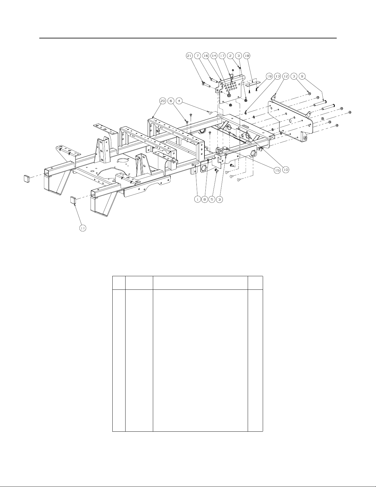
Frame Assembly- Figure 1 and Parts List
Ref.
No. Part No. Description Qty.
1 00002528 Hex Cap Screw 3/8-16 x 2.00 2
2 00012152
3 00022560 Hex Nut, 3/8-16 Flange Lock 11
4 01000372 Carriage Bolt, 3/8-16 x .75 Long 7
5 01000643 Carriage Bolt, 3/8-16 x 1 2
6 01001170 Rubber Bumper, .62 OD x .22 Thick 4
7 01001776 Clevis Pin, .500 Dia. x 2.50 Lg. 1
8 01002511
9 01003282
10 01003993 Linch Pin, 3/16 Dia. 2
11 01005160 Plug, Square Tube 2
12 01007779 Bracket Assembly, Frame, Front 1
13 01008225 Push Retainer, 3/8 4
14 01010119 Nut, 1/2-13, Flangelock 1
15 02002655 Spacer, .51 ID x .75 OD x 1.40 1
16 02003055 Lift Index Bracket 1
17 02003074 HitchPin, .120 Dia. x 3.0 1
18 02003501 Wear Plate, 1.25 x 5.00 1
19 02003505 Flat Head Cap Screw, 1/4-20 x .75 2
20 02003541 Frame Assembly 1
21 02003563 Carriage Bolt, 1/2-13 x 3.00 1
Lock Nut w/Nylon Insert
Nut, 3/8-16, Jam
Clevis Pin, .625 Dia x 4.375 Long
GD: 02003025-10/16/06
2
2
2
3
Page 4
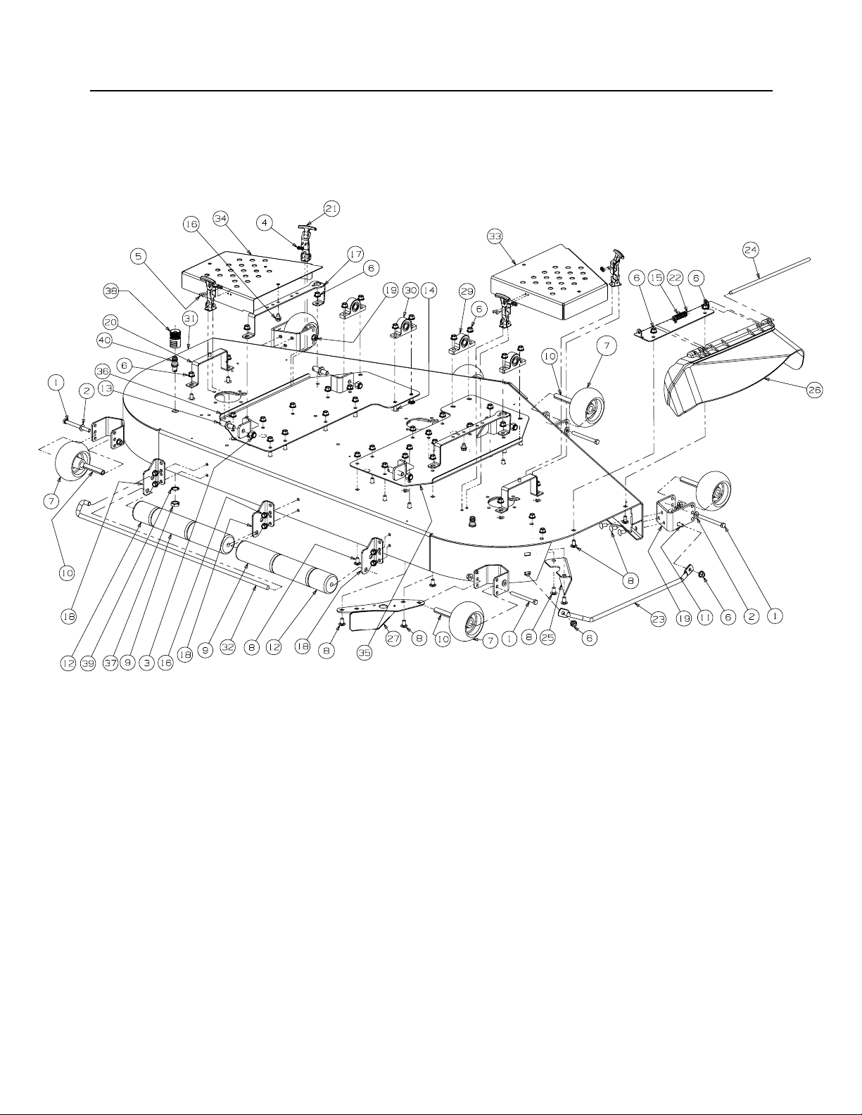
72" Fabricated Cutter Deck - Figure 2
GD: 02002933-10/26/06
4
Page 5
72" Fabricated Cutter Deck - Parts List for Figure 2
Ref.
Part No. Description Qty.
No.
1 00011925 Hex Cap Screw, 3/8-16, 3.75 6
2 00012158
3 00012428 Lock Nut, Nylon Insert, 1/2-13 4
4 00014608 Lock Nut, Nylon Insert, #10-32 16
5 00017778
6 00022560 Flange Lock Hex Nut, 3/8-16 61
7 01000343
8 01000372 Carriage Bolt, 3/8-16 x .75 Lg. 44
9 01000385 Front Roller 4
10 01000398 Wheel Spacer 6
11 01000643 Carriage Bolt, 3/8-16 x 1 2
12 01001169 Grass Catcher Roller 2
13 01001745 Pin, 5/8 Dia. x 1.2 Lg. 4
14 01002010
15 01003253 Torsion Spring, 0.4ID x 2.16Lg 1
16 01004304 Hex Index Washer Screw, 3/8-16, .5 8
17 01004685 Belt Cover Support 2
18 01005364 Deck Roller Mount Bracket 3
19 01005260
20 01005437 Outer Belt Cover Support Assembly 2
21 01005869
22 01008514
23 01008526
24 01009102 Pin, .375 x 14.06 1
25 01009300 Chute Bracket 1
26 01009705 Chute Deflector 1
27 01009843
28 01010119 Nut, 1/2-13, Flangelock 1
29 02000109
30 02000110
31 02002534 72 Deck Assembly 1
32
02002800 J-Hook w/ Threaded Roller 1
33 02002831 Right Hand Deck Belt Cover 1
34 02002832 Left Hand Deck Belt Cover 1
35 02002919
36 02002918
37 712-0641 Hex Nut, M16-1.5 2
38 721-04041 Water Nozzle Adaptor 1
39 736-0760 Lock Washer, 17 x 23.8 x 1.95 2
40 737-04003B Deck Water Nozzle 2
Flat Washer, 3/8
Phillips Head Screw, #10-32 x 1/2
Complete Wheel, 5.00 Dia.
Carriage Screw, 3/8-16 x 1.25
Anti-Scalp Wheel Front Mount Bracket
T-Handle Latch Draw
Chute Bracket
Finger Guard
Discharge Baffle Weldment
Pillow Block, Steel
Pillow Block, Bronze
Right Hand Deck Weldment Bracket
Left Hand Deck W eldm ent Bracket
6
16
6
7
4
4
1
1
1
3
1
1
1
5
Page 6
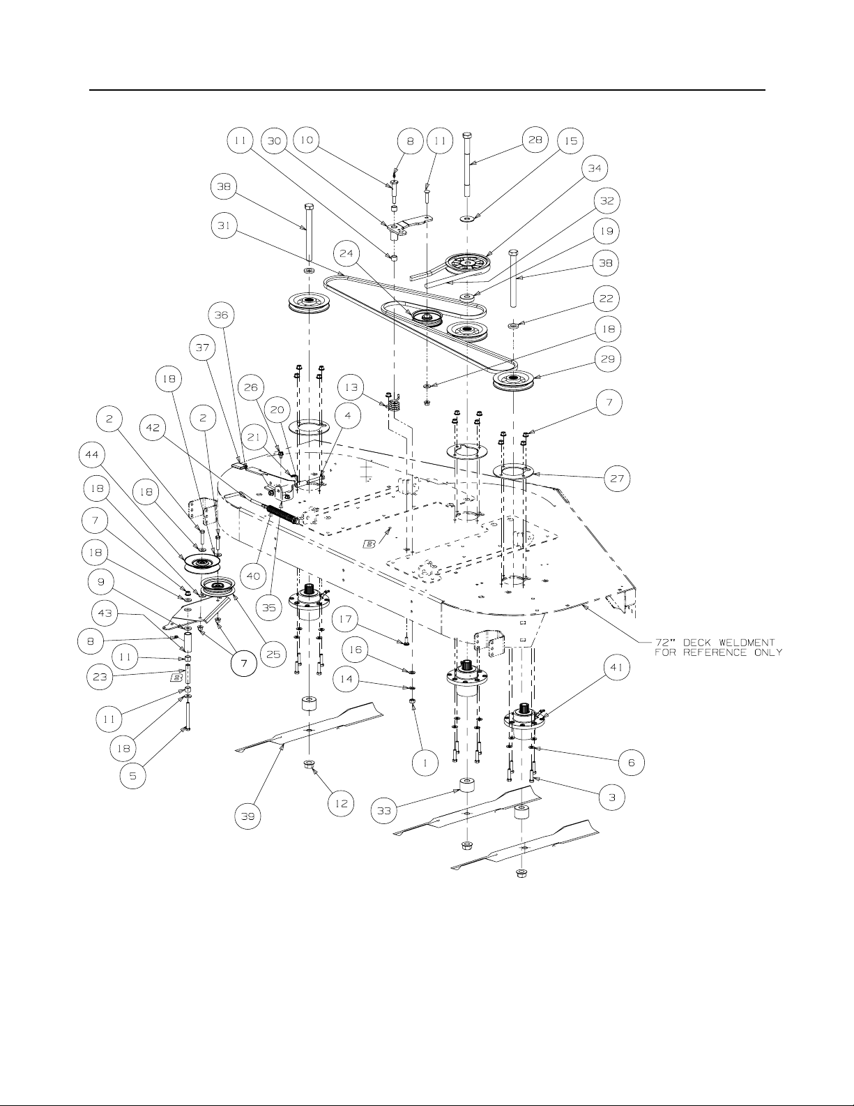
72" Fabricated Deck Spindle Assembly - Figure 3
GD: 02003628-10/30/06
6
Page 7
72" Fabricated Deck Spindle Assembly
Ref.
Part No. Description Qty.
No.
1 00005763 Hex Nut, 7/16-14 1
2 00008495 Hex Cap Screw, 3/8-16 x 1-3/4 2
3 00011438 Hex Cap Screw, 3/8-16 x 1-1/2 12
4 00011861 Hex Cap Screw, 3/8-16 x 2-1/2 1
5 00011925
6 00012158
7 00022560 Flange Lock Hex Nut, 3/8-16 18
8 00060078 Grease Fitting, 1/4-28 x 3/16 2
9 00083192 Idler Washer 1
10 01000302 Shoulder Screw, 7/16-14 1
11 01000364 Hex Carriage Screw, 3/8-16, 1.75 1
12 01000380 Flange Hex Nut, 3/4-16 3
13 01000387
14 01000389 Lock Washer, 7/16 1
15 01000392 Flat Washer, .781 ID 2.00 OD, .105 1
16 01000393 Flat Washer, .469 ID, .875 OD, .105 1
17 01000643
18 01000723
19 01002564 Spacer, .76 ID x 2.0 OD x .477 1
20 01002751
21 01002771 Cotter Pin, .072 x 1.12 Long 2
22 01003123 Spacer .812 ID x .268 LG 2
23 01003245
24 01004081 Flat Pulley 1
25 01004101
26 01004304 Screw, TT, 3/8-16 x .50, 2
27 01005434
28 01005388
29 01007499 V-Pulley, 5.75 OD 3
30 01007786
01000308
31 01007937
32 01007938
33 01008018
34 01008081
35 01008618
36 01008252
37 01008270
38 01008542 Hex Cap Screw, 3/4-16, 7.50 2
39 02000568 Bahia Blade, 25.0, .756 ID 3
40 02000726 Extension Spring, 1.0 x OD x 5.00 1
41 02000920 Aluminum Spindle Assembly 3
42 02001574
43 02003489 Idler Arm Assembly includes: 1
01000308 Bearing Sleeve 2
44 756-3045 Idler Pulley, 5.06 Dia. 1
Hex Cap Screw, 3/8-16, 4.00
Flat W asher , 3/8
Torsion Idl er Spring
Carriage Bolt, 3/8-16 x 1
Flat Washer, .406 ID, 1.0 OD, .105
Spacer, .39 ID x .63 OD x 1.75
Spacer, .39 ID x .625 OD x 2.75
Idler Pulley, 4.06 OD
Aluminum Spindle Support Plate
Hex Cap Screw, 3/4-16, 9.00
Idler Arm Assembly, Deck
Bearing Sleeve
V -Belt, B Section x 124.0 LG
V -Belt, B Section x 99 .25 LG
Spacer, .760 ID x 2.00 OD x .330
V -P ulley, 6.360 OD x .750 Bore, Cast
Tension Idler U-Bracket
Handle Tension Weldment
Tension Idler Handle Grip
Spring Tension Rod
- Parts List for Figure 3
1
12
1
1
6
1
1
1
3
1
1
2
1
1
3
1
1
1
1
1
7
Page 8
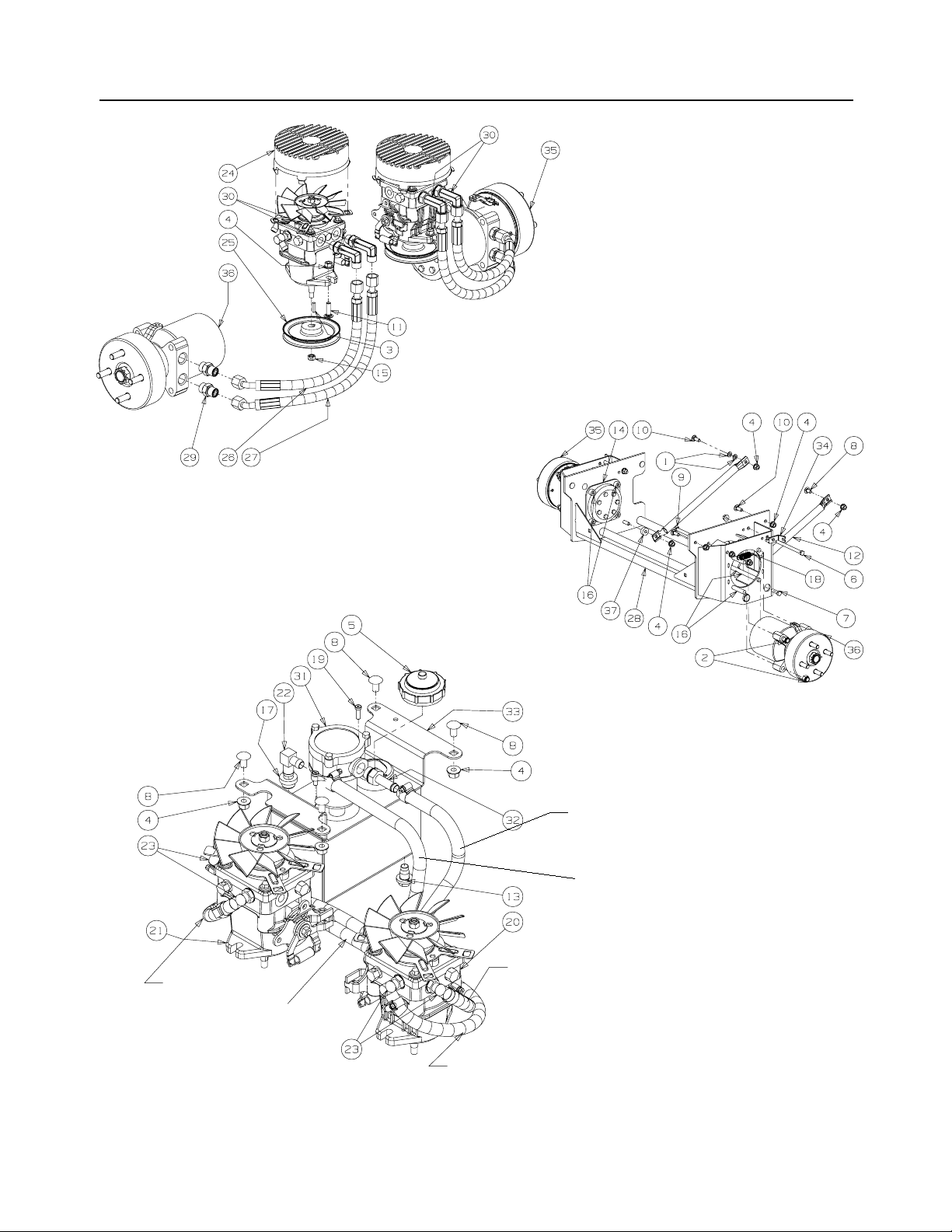
Hydro Hose and Pump Assembly - Figure 4
Pump & Motor Systems
3/4" Hose
16.0" LG.
3/4" Hose
12.0" LG.
Pilot &Drain Systems
Motor Mount Systems
3/4" Hose
11.0" LG.
3/4" Hose
12.0" LG.
3/4" Hose
12.0" LG.
3/4" Hose
16.0" LG.
GD: 02002830-10/05/06
8
Page 9

Hydro Hose and Pump Assembly- Parts List for Figure 4
Ref.
Part No. Description Qty.
No.
1 00012157 W asher lock 3/8 zinc 2
2 00012428 W asher lock 3/8 zinc 8
3 00020628 Key, 3/16" x 7/8" 2
4 00022560
5 00030261 Cap, Hydro Oil Tank 1
6 00034167 Hex Cap Screw 3/8-16 x 5.00 2
7 01000369 Hex Cap Screw, 3/8 -16 x 1.25 2
8 01000372 Carriage Bolt, 3/8-16 x .75 LG. 5
9 01000642 Carriage Bolt, 3/8-16 x 5.50
10 01000643 Carriage Bolt, 3/8-16 x 1 5
11 01002010 Carriage Screw, 3/8-16 x 1.25 4
12 01001618
13 01004192 Oil Pan Drain Plug w/ Seal 1
14 01006948
15 01007309
16 01008449
17 02000296 Grommet Fitting, .54 ID x .78 OD 1
18 02000401 Spring Extension, .740 OD x 2.656 2
02000841
19 02000905
01009631
20 02000906
21 01009631
22 02001151
23 02001160
24 02001169
25 02001172
26 02001178
27 02001179
28 02001492
29 02001715
02002003
30 02002257
31 02002258
32 02002557
33 02002703
34 02002899
35 02002967
36 02002968
37 750-3119 Spacer .406 ID x 1.0 OD 2
38 -39 02001175 Tee Fitting, 1/2 2
40 02002392
NOTE: Lubricant, 02002058 Quarts, 2.00
Flange Lock Hex Nut, 3/8-16
Strut Frame
Hydro Wheel Motor Backup Plate
Hex Nut, 3/8-24
Socket Head Capscrew, 1/2-13; 6-1/2
Socket Low Head Cap Screw, 1/4-20 x 0.75
Hydro Pump, BDP-12, RH
Kit, Fan
Hydro Pump, BDP-12, LH
Kit, Fan
Fitting Elbow Spur, 5/8 x 1/2
Fitting Elbow, 9/ 16 x 1/2
Fan Pump Shroud
Hydro Pump Pulley
Short Pressure Hose Assembly
Long Pressure Hose Assembly
Hydro Motor Frame Assembly
Adaptor Fitting, 8 x 10
Adaptor, 8 x 8
Hydraulic In-Tank Filter includes:
Replacement Filter
Fitting, 3/4 ORB x 1/2 Tube
Hydraulic Tank Assembly
Rear Cable Mounting Bracket
Hydro Motor, Left Hand Assembly w/ Brake & Drum
Hydro Motor, Right Hand Assembly w/ Brake & Drum
Fuel Hose, .50 ID x .75 OD (in inches)
Hose Clamp, 1/2
22
2
2
2
8
2
1
1
1
1
1
4
2
2
2
2
1
4
4
1
1
1
1
2
1
1
79
12
9
Page 10

Brake Assembly - Figure 5
10
GD: 02002926-01/03/07
Page 11

Brake Assembly
- Parts List for Figure 5
Ref.
Part No. Description Qty.
No.
1 00010958 Washer, 1/2 Zinc 1
2 00011447 Hex Cap Screw, 1/4-20, 1.00 1
3 00011450 Shoulder Bolt, 1/2 x 1/2 1
4 00014608 Lock Nut, Nylon Insert, 10-32 3
5 00022560 Flange Lock Hex Nut, 3/8-16 5
6 00030906
7 01000372 Carriage Bolt, 3/8-16 x .75 2
8 01000443
9 01000628
10 01000930 Washer, .508 ID x 1.0 OD x .020 4
11 01002766 Nut, 1/4-20, Hex Flange Lock 1
12 01008198 Left Hand Brake Cable 1
13 01008225 Push Retainer, 3/8 2
14 01008531 Screw, #10-32 x 0.500 2
15 01008539 U-Nut, 1/4-20 18
16 02000362 Bag, Debris Storage 1
17 02002797 Lower Panel, LH 1
18 02002796 Lower Panel, RH 1
19 02002823 Control Panel Cover, LH 1
20 02002889 Control Panel Cover, RH 1
21 02002864 Brake Cable Mounting Bracket 2
22 02002874 Cup Holder 1
23 02002971 Control Panel, LH 1
24 02002972 Control Panel, RH 1
25 02003010 Parking Brake Grip 1
26 02003603 Shoulder Bolt, 1/2 x 1.00, 3/8-16 2
27 02003725 Washer, 3/16 2
28 02003770 Brake Cable, LH 1
29 02003774 Brake Cable, RH 1
30 02003776 Brake Cable Bracket 1
31 02003782 Brake Lever 1
32 02003841 Centering Bracket 1
Phillips Head Machine Screw, 10-32 x 5/8
Screw Button Head, 1/4-20 x .5
Screw, TT, 1/4-20, 0.5, Hex Index Washer
3
18
10
11
Page 12

Fuel Tank Assembly - Figure 6 and Parts List
Ref.
No.
Part No. Description Qty.
1 02003809
2 00012470 Cable Tie 2
3 01000723
4 01000368
5 00012157 Lock Wa sher, 3/8 8
6 02003842
7 01000600 Flat Washer, 1.4 x .630 x .0515 1
8 01007425 Fuel Fitting 2
9 02001908 Fuel Hose Assembly includes: 1
00012235 Clamp, Union 5
01003473 Tee Fitting, Fuel 1
10 02002253
11 01000215 Hose Clamp, SAE #4: 1/4-5/8, SS 1
12 02003573
Fuel Cap, 3.5
Flat W asher, .406 ID, 1.0 OD, .105
Hex, Cap Screw, 3/8-16, .88
Fuel Tank
-- Hose, 1/4" Fuel Line (in inches) 88
Grommet, Fuel Tank
Plate, 16 Gauge
12
GD: 02001910-12/13/06
2
8
8
2
2
4
Page 13

Rear Bumper - Figure 7 and Parts List
Ref.
Part No. Description Qty.
No.
1 00012428 Hex Nut, 1/2-13, Insert Lock 2
2 00022560 Nut, Hex 3/8-16 Flange Lock 2
3 00030046 HHCS, 1/2-13, 3.00 2
4 01009992 Bar, Weight 2
5 02002536 Hitch Bracket 1
6 02003570
7 02003634
Carriage Bolt, 3/8-16 x 3.00
Rear Bumper
13
GD: 02003564-10/25/06
2
1
Page 14

Front Caster Assembly - Figure 8
14
GD: 02002925-10/04/06
Page 15

Front Caster Assembly -
Ref.
Part No. Description Qty.
No.
1 00012577 W asher, 1/2 x 1 Shim 2
2 00023287 Nut, 1/2-20, Center Lock 2
3 00060078
4 01000678
5 01002620 Cup Bearing 4
6 01002621 Bearing Cone 4
7 01002622 Seal 2
8 01002624 Ring Seal 4
9 01002626 Slotted Nut, 3/4-16 2
10 01002627 Cotter Pin, 5/32, 1.25 2
11 01003123 Spacer, .812 ID x .218LG 4
12 01006294
13 01006309 Hex Cap Screw, 1-14 x 5.0 1
14 01006347 Grease Cap, 1.986 OD 2
15 01006912 Wheel Spacer 2
16 01006961 HHCS, 1/ 2-20, 7.50 2
17 01007407 Yoke, Caster Wheel 2
18 01007760 Front Axle Assembly 1
19 01009997 Retainer Extension, Self Locking 1
20 02000588 Flat Washer, 1.00 ID x 2.00 OD x .075 2
21 02000589
22 02002821 Wheel, 13 x 6.50 x 6.0, Beige, includes 2
02002108 Tire 1
02002106 Roller Bearings 2
02002107 Retainer Bushings 2
Parts List for Figure 8
Grease Fitting
Nut, Jam, 1.0-14, Insert Lock
Bell Washer, 1.25 ID x 2.5 OD x .180
Spacer , 1.005 ID x 1.25 OD x 3.6
3
1
2
1
15
Page 16

Control Assembly- Figure 9
16
GD: 02002550-01/03/07
Page 17

Control Assembly -
Parts List for Figure 9
Ref.
No. Part No. Description Qty.
1 00002528 Hex Cap Screw, 3/8-16 x 2.00 4 28 01007734 Turnbuckle 2
2 00012186 Hex Nut, 1/4-20 1
3 00013131 Hex Cap Screw, 1/4-20, .75 1 30 01008367 B/Joint, 3/8-24, Left Hand Female 2
4 00013198 Hex Cap Screw, 5/16-18 x 2.00 2 31 01009322
5 00013416 HHCS, 1/4-20 x 1.00 1 32 01009377
6 00021958 Grease Fitting, 1/4-28, 45 degree 2 33 01009560 Control Rod, 3/8 x 17.312 2
7 00022560 Hex Nut, 3/8-16, Lock Flange 12 34 02000069
8 00061053 Washer, 3/8, SS 2 35 02002931 Lapbar Control Assembly, LH 1
9 01000371 Hex Cap Screw, 3/8-16 x 3.25 2 01004265
10 01000372 Carriage Bolt, 3/8-16 x .75 8 36 02002542 Brake/Control Rod 2
11 01000450 Hex Jam Nut, 3/8-24 4 37 02002543 Lapbar Control Arm 1
12 01000451 B/Joint, 3/8-24, Right Hand Female 2 38 02002545 Lapbar Pivot Bracket 2
13 01000600 Flat Washer, 1.4 x .630 x .0515 2 39 02002555
14 01000628
15 01000635 Nut, Lock, HexFlange, 5/16-18 9 41 02002932 Lapbar Control Assembly, RH 1
16 01000960 Belle Washer, .325 x .930 x .045 2 01004265
17 01001170 Rubber Bumper, .62 OD x .22 Thick 2 42 02003024 Lapbar Assembly includes: 2
18 010
19 01002766 Hex Flange Lock Nut, 1/4-20 2 02002662
20 01002986
21 01003561
22 01003947 U-Nut, 3/8-16, .75 2 45 02003664
23 01004003
24 01004129 Spacer, .385 ID x .75 OD x .875 2 47 02003880
25 01005851
26 01006350 Shaft Collar 2 49 732-0470A
27 01007312
02511 Nut, 3/8-16, Jam
Screw , TT, 1/4-20, 0.5, Hex Index Washer
Nut, 3/8-24, Jam, LH Third
Nut, Hex, Center Lock, M8
Flat W asher, 5/8 Nylon
External Washer, 3/8
Spacer, .625 OD x .385 ID x 1/2
Ref.
No. Part No. Description Qty.
29
01008225 Push Retainer 2
Shoulder Bolt, 1/4 x 1/4
Nut w/ Star Washer, 10-24
Screw, Shoulder Control Rod
Bearing
Lapbar Control Shaft Assembly
3 40 02002657
4 02002549
2 43 02003419
4 44 02003653
4 46 02003885
2 48 710-0262 Carriage Bolt, 5/16-18 x 1.50 4
2
Lapbar/Brake Control Mounting Bracket
Bearing
Control Handle Pivot Tube
Grip, 1.0
Bushing, .310 x .172 x .688 x .06
Cylinder Return to Neutral
Spacer, .405 ID x 1.0 OD x .72
Side Panel, Control, Left
Side Panel, Control, Right
Extension Spring, .53 OD x 4.75
2
2
3
2
1
1
2
2
2
4
2
1
1
1
1
17
Page 18

Wheel Assembly - Figure 10 and Parts List
2
1
Ref.
Part No. Description Qty.
No.
1 00012187 Lug Nut, 1/2-20 8
2 02002668
00073975
01002182
01004473
Wheel Assembly, 24 x 12.00-12, Beige Includes:
Tire, 24 x 12.00-12, Turf Master
Rim, 12 Dia x 8.50 width
OPTIONAL TIRES
Wheel Assembly, 24 x 12.00-12, Turf Saver
Tire, 24 x 12.00-12, Turf Saver
GD: 02002669-10/04/06
2
18
Page 19

Seat/Floor Panel Assembly- Figure 11 and Parts List
GD: 02002559-12/19/06
Ref.
No.
Part No. Description Qty.
1 00002528 Hex Cap Screw 3/8-16 x 2.00 1 16 01001170 Rubber Bumper, .62 OD x .22 Thick 2
2 00006131
3 00012158 Washer AR 18 01008140
4 00012165 Nylock Nut, 5/16-18 2 19 01009459
5 00012168 Lock Washer, 5/16 4 20 02002091 Shoulder Bolt, 1/2 x 3/4, 3/8-16 1
6 00012178 Hex Cap Screw, 5/16-18 x 1/2 4 21 02002335 Floor Panel Assembly 1
7 00012428 Nut, 1/2-13, Nylon Insert 4 22 02002714 Foldable Rops Assembly 1
8 00013131
9 00021956 Hair Pin, 3/8-1/2 2 24 02002963
10 00022560 Flange Lock, Hex Nut, 3/8-16 4 25 02002964
11 01000226
12 01000372 Carriage Bolt, 3/8-16 x .75 Long 2 27 02003748
13 01000523
14 01000628
15 01000873 Washer, .536 ID x .930 OD x .05 8 30 02003745 Adjustable Stud 1
Hex Nut, 3/8-16
Screw, Hex, Cap, 1 /4-20 x .75
Hex Cap Screw, 1/2-13 x 3.50
Nut, #10-24, Nylon Lock
Screw, TT, 1/4-20, 0.5, Hex Index Washer
Ref.
No.
Part No. Description Qty.
2 17 01002766 Lock Nut, 1/4-20 1
Deck Lift Spring, Left Hand
Shoulder Bolt, .375 x 1.50
1 23 02002942 Seat w/ Seat Belt & Suspension 1
Rubber Stop with Washer
Standard Cap Screw, #10-24 x .75
4 26 02002344
4 28 02003732
2 29 02003739
Seat Plate Assembly
Seat Latch Bracket
Latch Lever Bracket
Latch Bracket
19
1
2
4
4
1
1
1
1
Page 20

37HP Kawasaki Engine Assembly - Figure 12
Description Part Number
Air Filter
Air Filter (Inner)
Fuel Filter
Oil Filter
Spark Plug
GD: 02003537-09/26/06
20
Page 21

37HP Kawasaki Engine Assembly
Ref
Part No. Description Qty.
No
1 00005763 Hex Nut, 7/16-14 1
2 00010980 Hex Head Cap Screw, 3/8-16 x 1.50 4
3 00012157 Washer lock 3/8 zinc 4
4 00014602
5 00014608
6 00022560 Flange Lock, Hex Nut, 3/8-16 2
7 00060056
8 00060078
9 01000302 Shoulder Screw, 7/16-14 1
10 01000364
11 01000389 Lock Washer, 7/16 2
12 01000721 Machine Screw, 8-32, .375 2
13 01000723
14 01000728
15 01000811 Screw, #8-32 x .375 2
16 01001395 Capscrew, 7/16-20 x 2.50 1
17 01002601 Hex Cap Screw, 3/8-16, .750 1
18 01003269 Flat Washer, 7/16 ID x 1.75 OD x .25 1
19 01003283 Oil Drain Hose 1
20 01004004 Control Throttle Knob 2
21 01004081 Flat Pulley with Flanges 1
22 01005006 Engine Idler Arm 1
01000308 Bearing 2
23 01005104 Pump Drive Pulley 1
24 01005314 Flat Washer, 7/16 ID x 1.75 OD x .25 1
25 01005856
26 01007015 Belt, 51.2 Lg 1
27 01007713
28 01008623 Muffler Accessory Exhaust Tube 1
29 01009635
30 02003421 Throttle, Control Cable 1
31 02003422 Choke, Control Cable 1
32 02003521 Engine, 37HP Kawasaki 1
33 02003522
34 02003550 Retainer Clutch Assembly 1
Note: Engine Oil 10W40
Round Hd. Machine Screw, 10-32 x 3/4
Lock Nut, Nylon Insert, 10-32
Nut W asher , W/S tar , 8-32
Grease Fitting, 1/4-28 x 3/16
Hex Carriage Screw, 3/8-16, 1.75
Flat W asher, .406 ID, 1.0 OD, .105
Clip, Heat Shield Cable
Key, 1/4 x 1/4 x 3
Clutch Brake, 1.125 ID
Extension Spring, .98 OD x 5.00
Muffler, Kawasaki
- Parts List for Figure 12
2
2
2
1
1
1
1
1
1
1
1
21
Page 22

Electrical Assembly
Kawasaki
- Figure 13
Fasten relay (01002251) with self-tapping screw
(01000628) on LH control panel shown in Fig. 11.
GD: 02002937-12/15/06
22
Page 23

Electrical Assembly
Ref.
No.
Kawasaki
Part No. Description Qty.
1 00012032 Battery, 12V 225CCA 30 Min 1
2 00012470
3 00013131
4 00013258
5 00014602
6 00014608
7 00022560 Flange Lock, Hex Nut, 3/8-16 4
8 00032097
9 01000372 Carriage Bolt, 3/8-16 x .75 Long 4
10 01001811
11 01002111 Switch, Electric, PTO 1
12 01002251 Relay, 12V 40A 1
13 01002766 Lock Nut, 1/4-20 2
14 01003581 Switch, Ignition, 6 Pin 1
15 01004040 Grommet, .75 ID 1
16 01004078 Cable, Battery Red, 28" 1
17 01005389
18 01009905
19 02000024 Switch, Safety N.O./N.C. 1
20 02002059 Cable, Battery, Red, 42" 1
21 02002552 Battery Bracket 1
22 02002592 Control/Brake Panel Switch 1
23 02002822 Wire Harness Adaptor 1
24 02002824
25 02003775
26 02003038
27 723-3064 Strap, Battery 1
- Parts List for Figure 13
Tie, Cable, 3/16 x .05 x 7.4"
Screw, Hex, Cap, 1/4-20 x .75
Boot, 1" OD Rubber Battery-PST, Red
Round Hd. Machine Screw, 10-32 x 3/4
Lock Nut, Nylon Insert
Nut, W/Cap, 5/8-32 Ignition
Hourmeter, Harness (not shown)
Meter, Hour
Bracket, PT O Switch Retainer
Harness Assembly (not shown)
Electrical Conduit Clip, 5/8
Electrical Conduit Clip, 3/8
5
2
2
2
2
1
1
1
1
1
2
1
23
Page 24

Lift Assembly - Figure 14
24
GD: 02003030-10/31/06
Page 25

Lift Assembly
- Parts List for Figure 14
Ref.
Part No. Description Qty.
No.
1 00002766 W asher, 1.5 x .655 x .055 4
2 00010734 Lock Washer, 1/2 1
3 00011459 Flat Washer, 1/2 1
4 00011951 Hex Cap Screw, 1/2-13 x 1.50 1
5 00012152
6 00012165 Nut, 5/16-18, Nylock
7 00013432
8 00022560 Hex Nut, Flange Lock, 3/8-16 5
9 00035632
10 00060018 Cotter Pin, 3/16 x 1-1 2
11 01000872 Flat Washer, 1.25 x .411 x .100 1
12 01001744
13 01007255 Eye Bolt Mount Link, 5/8 ID 2
14 01001855 Ferule Lift 4
15 01001857 Lift Connector Rod 2
16 01001930 Hex Flange Bearing, 1.25 ID 4
17 01002586 Front Lift Link, Rod Mount 1
18 01003123 Spacer, .812 ID x .268 Lg. 3
19 01003535
20 01003993 Linch Pin, 3/16 Dia. 8
21 01003994 E Clip, 3/4 Dia. 4
22 01004003 Nylon Flat Washer, 5/8 6
23 01004127
24 01006408 Flat Washer, 1.25 ID 4
25 01006823
26 01007487
27 01007526
28 01007527 Spacer, .630 ID x 1.06 OD x .440 3
29 01007544 Deck Lift Li nk Rod 2
30 01008206
31 01007681 Deck Lift Shaft 2
32 01008209
33 01007962
34 01008801 Rivet, 1/4 x 5/8 7
35 01010119 Nut, 1/2-13, FlangeLock 1
36 02003566 Deck Link 2
37 02002708 Bearing Lift Brac e Asse mbl y, Left Hand 1
00060078 Grease Fitting 1
02002384 Bearing 2
38 02002709
00060078
02002384
39 02002596 Deck Lift Foot Pedal 1
40 02002595 Deck Lift Foot Pedal Weldment 1
41 02002959 Lift Compression Spring 2
42 02003050
43 02003042 Lift Link Bracket 1
44 02003043
45 02003511
46 02003501
47 02003505 Flat Head Cap Screw, 1/4-20 x .75 2
48 02003585 HHCS, 1/2-13 x 2.50 1
49 02003586 Spacer, .76 ID x 1.0 OD x .75 1
50 02003587 Spacer, .50 ID x .75 OD x 1.313 1
51 02003588 Torsion Spring, .120 Wire x 1.32 OD 1
52 736-0188 Washer, .76 x 1.49 x .06 3
Lock Nut w/Nylon Insert
Flat W asher, 5/8
Jam Nut, 5/8-11
Eye Bolt, 5/8ID
Shoulder Screw, 0.625 OD x .437 Lg.
HHCS, 3/8-16, 3.00
Hose, 5/8 ID 13/16 OD, 8" LG
Rod End, Male
Jam Nut, 5/8-18
Bellecrank W eldment Assembly
Front Frame Strut Assembly
Socket Head CapScrew, 5/16-18 x 2
Bearing Lift Brace Assembly, Right Hand
Grease Fitting
Bearing
Lift Tube, 3.0 x 1.5
Spacer, .375 ID x .625 OD x 1.53
Yoke Plate
Lift Wear Plate
2
8
4
14
2
4
1
2
2
2
3
2
8
1
1
2
1
1
1
1
25
Page 26

Decal Map
01006087 777D10677 00030633
777D10677
01002166
Near deck wash out
under belt cover
Top of deck
00030635
777D10679
02003753
(Beside S/N Label)
On top of front rail
on main frame
01007756
Aligned near fuse mounting holes
on inner side control panel
02003616
02003514
777S32801
Near deck wash out
777D10679
Foot Platform
777D09015
On bottom of
02003676
Hydraulic Tank
02002041
On top of
Both sides of unit
777D09752
Centered on rear bumper
02003753
Centered top of Tow Hitch
02002693
777S32797
26
Page 27

This Page Intentionally Left Blank
27
Page 28

Form No. 02003431 Rev. 07-0 09/14/2006
Cub Cadet Commercial
P.O. Box 368023
Cleveland, OH 44136
 Loading...