

Page 1

Operator’s Manual
Single Stage
Snow Thr ower
Models 521R & 521E
IMPORTANT: Read safety rules and instructions carefully
Warning: This unit is equipped with an internal combustion engine and should not be used on or near any unimproved forest-
covered, brush-covered or grass-covered land unless the engine’s exhaust system is equipped with a spark arrester meeting
applicable local or state laws (if any). If a spark arrester is used, it should be maintained in effe c tive working order by the operator.
In the State of California the above is required by law (Section 4442 of the California Public Resources Code). Other states may have
similar laws. Federal laws apply on federal lands. A spark arrester for the muffler is available through your nearest engine authorized
service dealer or contact the service department, P.O. Box 368023 Cleveland, Ohio 44136-9722.
CUB CADET CORP. P.O. BOX 368023 CLEVELAND, OHIO 44136-9 722
PRINTED IN U.S.A.
FORM NO.
770-10050A.fm
(12/99)
Page 2
TABLE OF CONTENTS
Content Page
Important Safe Operation Practices .................................................................. 3
Assembling Your Snow Thrower....................................................................... 5
Know Your Snow Thrower................................................................................. 7
Operating Your Snow Thrower.......................................................................... 8
Making Adjustments.......................................................................................... 9
Service.............................................................................................................. 10
Maintaining Your Snow Thrower ....................................................................... 11
Off-Season Storage .......................................................................................... 11
Troubleshooting ................................................................................................ 12
Parts List ........................................................................................................... 13
FINDING MODEL NUMBER
This Operator’s Manual is an important part of your new snow thrower. It will help you to assemble, prepare and
maintain the unit for best performance. Please read and understand what it says.
Before you start assembling your new snow thr ower, ple ase locate t he model pl ate on the
equipment and copy the information from it in the space provided below. The information on the
model plate is very important if you need help from our Customer Referral Line or an authorized
dealer.
• You can locate the model number by standing behind the unit in the operating position and looking down at
the dash panel . A sample model plate is explained below. For future reference, please copy the model
number and the serial number of the equipment in the space below.
(Model Number)
(Serial Number)
Copy the model number here:
Copy the serial number here:
CUB CADET CORP.
P.O. BOX 3680 23
CLEVELAND, OHIO 44136
CALLING CUSTOMER SUPPORT
If you have difficulty assembling this product or have any questions regarding the controls, operation or
maintenance of this unit, please call the Cub Cadet Customer Dealer Referral Line at 1-(800)-528-1009.
Please have your unit’s model number and serial number ready when you call. See previous section to
locate this information. By having the model and serial numbers ready, you help your Cub Cadet dealer
give you faster service.
2
Page 3

SECTION 1: IMPORTANT SAFE OPERATION PRACTICES
WARNING: This symbol points out important safety instructions which, if not followed, could endanger
the personal safety and/or property of yourself and others. Read and follow all instructions in this manual
before attempting to operate your snow thrower. Failure to comply with these instructions may result in
personal injury. When you see this symbol, heed its warning.
DANGER: Your snow thrower was built to be operated according to the rules for safe operation in this
manual. As with any type of power equipment, carelessness or error on the part of the operator can result
in serious injury. If you violate any of these rules, you may cause serious injury to yourself or others.
WARNING: The Engine Exhaust from this product contains chemicals known to the State of
California to cause cancer, birth defects or other reproductive harm.
Training
• Read this operator's manual carefully in its entirety
before attempting to assemble or operate this
machine. Be completely familiar with the controls
and the proper use of this machine before
operating it. Keep this manual in a safe place for
future and regular reference and for ordering
replacement parts.
• Never allow children under 14 years old to operate
a snow thrower. Children 14 years old and over
should only operate snow thrower under close
parental supervision. Only persons well
acquainted with these rules of safe operation
should be allowed to use your snow thrower.
• No one should operate this unit while intoxicated or
while taking medication that impairs the senses or
reactions.
• Keep the area of operation clear of all persons,
especially small children and pets.
• Exercise caution to avoid slipping or falling,
especially when operating in reverse.
Preparation
• Thoroughly inspect the area where the equipment
is to be used and remove all door mats, sleds,
boards, wires and other foreign objects.
• Disengage all clutches and shift into neutral before
starting engine.
• Do not operate equipment without wearing
adequate winter outer garments. Do not wear
jewelry, long scarfs or other loose clothing which
could become entangled in moving parts. Wear
footwear which will improve footing on slippery
surfaces.
• Before working with gasoline, extinguish all
cigarettes and other sources of ignition. Check the
fuel before starting the engine. Gasoline is an
extremely flammable fuel. Do not fill the gasoline
tank indoors, while the engine is running, or until
engine has been allowed to cool at least two
minutes. Replace gasoline cap securely and wipe
off any spilled gasoline before starting the engine
as it may cause a fire or explosion.
• Use a grounded three wire plug-in for all units with
electric drive motors or electric starting motors.
• Adjust collector housing height to clear gravel or
crushed rock surface.
• Never attempt to make any adjustments while
engine is running (except where specifically
recommended by manufacturer).
• Let engine and machine adjust to outdoor
temperature before starting to clear snow.
• Always wear safety glasses or eye shields during
operation or while performing an adjustment or
repair, to protect eyes from foreign objects that
may be thrown from the machine in any direction.
Operation
• Do not put hands or feet near or under rotating
parts. Keep clear of discharge opening and auger
at all times.
• Exercise extreme caution when operating on or
crossing gravel drives, walks, or roads. Stay alert
for hidden hazards or traffic.
• After striking a foreign object, stop the engine,
remove wire from spark plug, and thoroughly
inspect the snow thrower for any damage. Repair
the damage before restarting and operating the
snow thrower.
• If the snow thrower should start to vibrate
abnormally, stop the engine and check
immediately for the cause. Vibration is generally a
warning of trouble.
• Stop engine whenever you leave the operating
position, before unclogging the collector/impeller
housing or discharge guide, and making any
repairs, adjustments, or inspections. Never place
your hand in the discharge or collector openings.
Use a stick or wooden broom handle to unclog the
discharge opening.
• Take all possible precautions when leaving the unit
unattended. Disengage the collector/impeller, shift
into neutral, stop the engine, and remove the key.
• When cleaning, repairing, or inspecting, make
certain collector/impeller and all moving parts have
3
Page 4
stopped. Disconnect spark plug wire and keep
away from plug to prevent accidental starting.
• Do not run engine indoors, except when starting
engine and transporting snow thrower in or out of
building. Open doors. Exhaust fumes are
dangerous.
• Do not clear snow across the face of slopes.
Exercise extreme caution when changing direction
on slopes. Do not attempt to clear steep slopes.
• Never operate snow thrower without guards,
plates, or other safety protection devices in place.
• Never operate snow thrower near glass enclosure,
automobiles, window wells, drop off, etc., without
proper adjustments of snow thrower discharge
angle. Keep children and pets away.
• Do not overload machine capacity by attempting to
clear snow at too fast a rate.
• Never operate the machine at high transport
speeds on slippery surfaces. Look behind and use
care when backing.
• Never direct discharge at bystanders or allow
anyone in front of unit.
• Disengage power to collector/impeller when
transporting or not in use.
• Use only attachments and accessories approved
by the manufacturer of snow thrower (such as
wheel weights, counter weights, cabs, etc.).
• Never operate the snow thrower without good
visibility or light. Always be sure of your footing and
keep a firm hold on the handles. Walk, never run.
• Muffler and engine become hot and can cause a
burn. Do not touch.
Maintenance And Storage
• Check shear bolts, engine mounting bolts, etc., at
frequent intervals for proper tightness to be sure
equipment is in safe working condition.
• Never store the machine with fuel in the fuel tank
inside a building where ignition sources are present,
such as hot water and space heaters, clothes
dryers, and the like. Allow engine to cool before
storing in any enclosure.
• Always refer to operator's manual instructions for
important details if snow thrower is to be stored for
an extended period.
• Run machine a few minutes after throwing snow to
prevent freeze up of collector/impeller.
• Check clutch controls periodically to verify they
engage and disengage properly and readjust if
necessary. Refer to operator's manual for
adjustment instruction s.
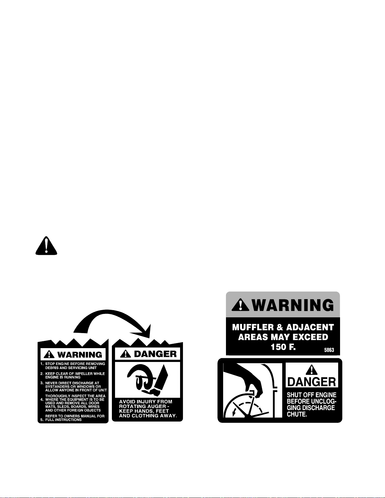
Y our Responsibility
Restrict the use of this power machine to persons who read, understand and follow the warnings and
instructions in this manual and on the machine. Some of the safety labels are reproduced below. Review
them and follow their instructions.
4
Page 5
SECTION 2: ASSEMBLING YOUR SNOW THROWER
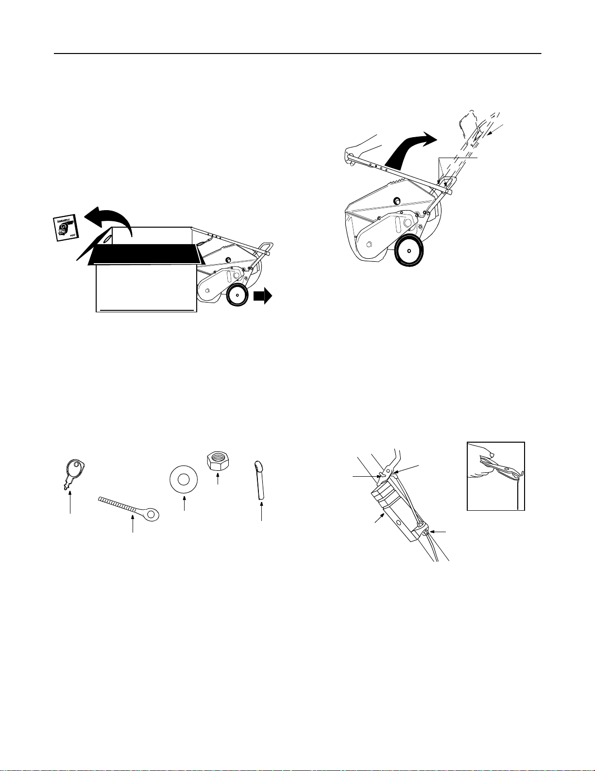
Unpacking from carton
• Cut along corners of the carton and lay it down flat.
See Figure 1. Remove packing material.
• Remove any loose parts included with unit (i.e.,
operator’s manual, etc.).
• Roll unit out of carton. Check carton thoroughly for
any remaining loose part.
Remove loose parts
Raise
handle
to here
Hand Knobs
Figure 3
Roll unit out
Figure 1
Hardware pack (Figur e 2)
1. Ignition Keys (2)
NOTE: One key is in the switch on the snow thrower.
2. Eyebolt
3. Saddle Washer 5/16" I.D.
4. Hex Nuts 5/16-18 Thread (2)
5. Cotter Pin
Hex Nut
Ignition
Key
Eye Bolt
Saddle
Washer
Figure 2
Cotter
Pin
Items required for assembly
1. Pair of pliers (not necessary, but helpful)
2. Two cycle engine oil
3. Fresh gasoine
NOTE: Al l references to left or right side of the snow
thrower is from the operating position only.
Raising upper handle
• Loosen the hand knob on each side of the handle.
Remove packing material, if any.
• Raise the upper handle in the direction shown in
Figure 3 till it clicks into the operating position.
Make sure not to pinch or crimp the cable.
• Tighten the hand knobs.
Attaching control cable
The control cable may already be attached to the
control handle. If not attached, complete the following
steps to attach it to the snow thrower control housing.
Bottom
Hole In
Control
Handle
Control
Housing
• Route the control cable over the lower handle.
Insert the end of the cable into the hole in the
control housing as shown in Figure 4. Push the
plastic fitting until it locks into the control housing.
• Lift the control handle up, and hook the “Z” end of
the control cable into the bottom hole in the
control handle, from the outside to the inside. If
necessary, pull up on the end of the cable with a
pair of pliers to obtain slack in order to hook it into
“Z” End
of Cable
Figure 4
Plastic
Fitting
5
Page 6
the control handle. Hold the “Z” fitting with the
pliers, not the cable, to avoid damaging the cable.
NOTE: The upper h ole in the con trol handle p rovides
for adjustment in belt tension. Refer to Belt Tension
Adjustment Section of this manual for instructions.
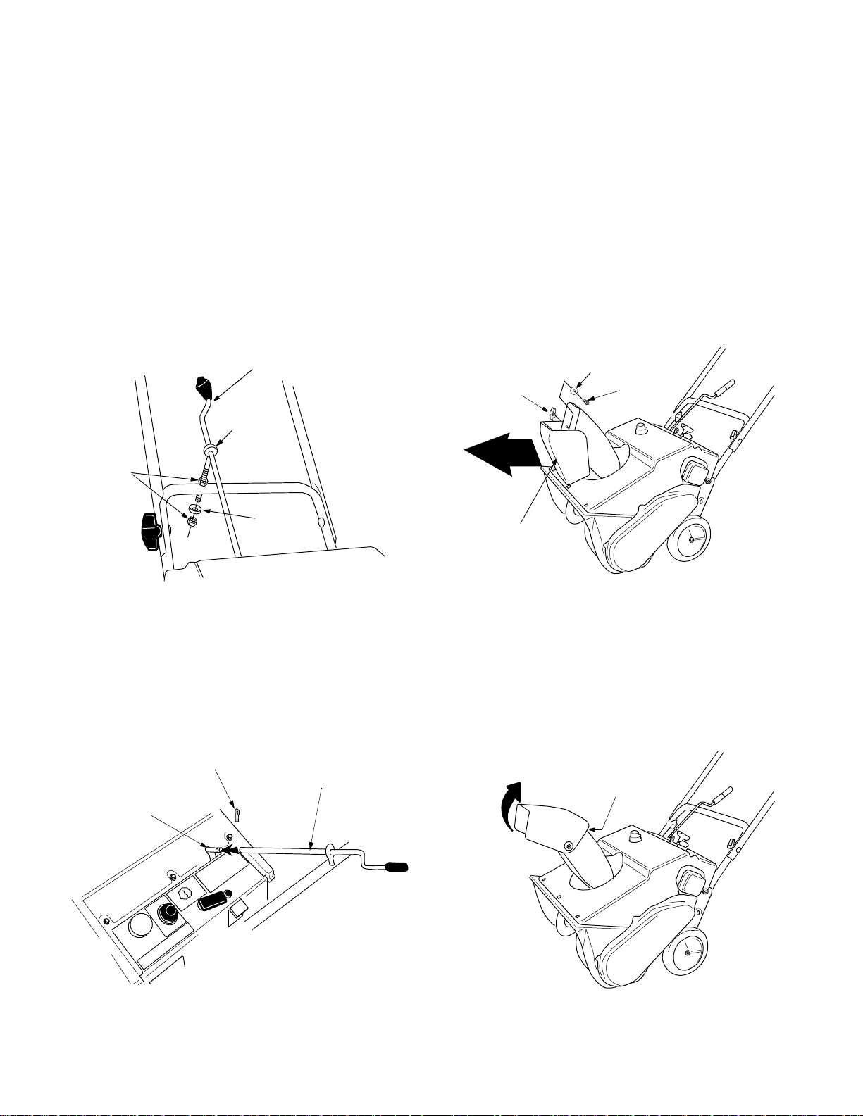
Installing chute crank
• Thread one 5/16” hex nut all the way onto the
eyebolt. See Figure 5. All necessary hardware is
included in the hardware pack shipped with your
unit. See Figure 2 for more details.
• Slide the eyebolt onto the chute crank. Insert
eyebolt into the hole in the lower handle.
• Secure eyebolt with 5/16” saddle washer and hex
nut. The cupped side of washer goes against the
handle. Adjust lower hex nut until the eyebolt is
positioned so that the chute crank turns freely
(does not bind ).
• Move upper hex nut down against the lower
handle. Tighten lower hex nut securely.
Assembling the chute
The snow thrower has been shipped with the upper
chute pivoted all the way down. Assemble as follows:
• Turn the chute crank until the chute faces straight
to the front. See Figure 7.
Chute Crank
Eye Bolt
Hex
Nuts
Saddle
Wash er
Figure 5
• Insert the chute crank into the coupler at the top
right side of the snow thrower. See Figure 6.
• Rotate the crank to align holes, and insert the
cotter pin. Bend ends of cotter pin in opposite
directions to secure. See Figure 6.
Cotter Pin
Chute Crank
Coupler
Flat
Hand
Knob
Front
Upper
Chute
Washer
Carriage
Bolt
Figure 7
• Remove the hand knob, flat washer and carriage
bolt from the upper chute. See Figure 7.
• Pivot the upper chute up so that there is no gap
between the upper and the lower chute. See
Figure 8. Secure with hardware just removed.
No
Gap
Figure 6
Pivot
upper
chute
Figure 8
6
Page 7

SECTION 3: KNOW YOUR SNOW THROWER
Read this owner’s manual and safety rules and labels before operating your snow thrower. Compare the
illustrations in Figure 9 with your equipment to familiarize yourself with the location of various controls and
adjustments. Save this manual for future reference.
WARNING: The operation of any snow thrower can result in foreign objects being thrown into the
operator’s eyes and cau sing s evere ey e damage . Always we ar safet y glasses w hile ope rating the
snow thrower, or while performing any adjustments or repairs on it.
Auger Control
Handle
Chute Crank
Discharge Chute
Shave
Plate
Auger
* Only on model 521E
IMPORTANT: This unit is shipped without gasoline or
oil. See separate engine operator’s manual for proper
fuel and engine oil recommendations.
Starter Handle
This is used to manually start the engine.
Auger Control Handle
Located on the upper handle, the auger control handle
is used to engage and disengage the augers. The
snow thrower is designed to be propelled by the
rotation of the augers.
Chute Crank
Located on right side of dash panel, the chute crank
determines the direction that snow will be discharged.
Turn clockwise to discharge snow to the left; turn
counterclockwise to discharge to the right.
Discharge Chute
The angle of the discharge chute controls the distance
that the snow is thrown. Tilt the discharge chute up for
greater distance; tilt down for less distance. Loosen
the hand knob on the side of the discharge chute to
Figure 9
Upper Handle
Spark
Plug
Cover
Choke Lever
Off
Primer
Button
On
Starter
Handle
Ignition
Key
Electric
Starter*
Plug for
Electric
Cord*
adjust. Til t the chute to the desi red posit ion, and
tighten the knob.
Choke Lever
This lever is located on the engine and has to be
placed in “ON” position to start a cold engine.
Primer Button
This is also located on the engine and is used to inject
fuel directly into the carburetor to start a cold engine.
Do not use it to start a warm engine. Follow engine
manual to prime engine.
Ignition Key
This key has to be placed in the “ON” position to start
the engine.
Spark Plug Cover
Spark plug is located under the cover.
Electric Starter (If equipped)
This is used to start engine with a 120V power source.
Plug for Electric Start (If equipped)
The electric starter requires use of a two prong
outdoor extension cord and a 120V power source.
7
Page 8

SECTION 4: OPERATING YOUR SNOW THROWER
Fuel and oil mixture
WARNING: Handle gasoline carefully;
remember that it is highly flammable.
Never fill fuel tank indoors, when engine is
running or while engine is still hot. Do not
smoke when filling fuel tank.
Your snow thrower uses a two cycle engine that
requires a mixt ure of gasoline and two cycle en gine
oil. Refer to the engine operator’s manual for proper
oil and fuel recommendations.
• A plastic cup was provided inside the fuel fill
opening on the fuel tank. Remove and discard this
cup before filling up the tank. Use the seperate
fuel tank cap to close after fill-up.
Starting engine
• To start the engine of your snow thrower, follow
the starting instructions in the engine operator’s
manual.
Operating snow throwe r
• Loosen hand knob on the upper discharge chute
and adjust chute up or down as shown in Figure
10. Then use the chute crank to position the entire
discharge chute in order to discharge snow with
the wind.
Upper Discharge
Chute
e
c
Change
position by
chute crank
s
s
e
L
a
t
s
i
D
Hand
Knob
r
e
t
a
e
r
n
a
G
t
s
i
D
e
c
n
• Release the auger control handle to stop the snow
throwing action and the forward motion.
Press auger
control handle
to engage
auger
Turn handle
to change
discharge
direction
Figure 11
Stopping engine
• Run the engine for a few minutes before stopping
to help dry up any moisture on the engine.
• Turn ignition key to OFF position and remove it
from the snow thrower.
IMPORTANT: Keep the ignition key in a safe place.
Engine will not start without it.
• Wipe all snow and moisture from the unit. Move
the choke lever back and forth several times and
leave it in the ON position.
Operating tips
• For most efficient snow removal, remove snow
immediately after it falls.
• Discharge snow downwind whenever possible.
Slightly overlap each previously cleared path.
• Lifting up on the handle will allow the rubber on the
augers to propel the snow thrower forward.
Pushing downward on the handle will raise the
augers off the ground and stop the forward motion.
Figure 10
WARNING: Do not throw snow towards a
building as objects could be discharged
with enough force to cause damage.
• After making sure no bystanders or obstacles are
in front of the unit, engage the auger control
handle. See Figure 11. As the snow thrower starts
to move, maintain a firm hold on the handle, and
guide the snow thrower along the path to be
cleared.
NOTE: Excessive u pward p ressur e on the h andle will
result in premature w ear on the rubber auger blades
which will not be covered by warranty.
• Run the engine for a few minutes before stopping
to help dry any moisture on the engine.
• Clean the snow thrower thoroughly after each use.
WARNING: Do not operate this snow
thrower on gravel as loose gravel can
easily be picked up and thrown by the
auger, causing injury to people around
and/or damage to the snow thrower.
8
Page 9
SECTION 5: MAKING ADJUSTMENTS
WARNING: NEVER attempt to clean chute
or make any adjustments or re p airs w hile
the engine is running.
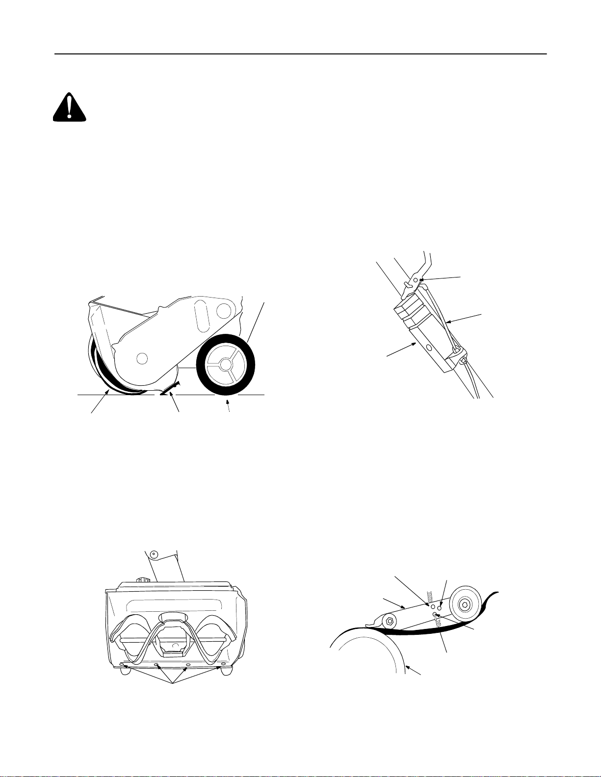
Shave plate
• To check the adjustment of the shave plate, place
the unit on a leve l surface. See Figure 12. The
wheels, shave plate and augers should all contact
the level surface. Note that if the shave plate is
adjusted too high, snow may blow under the
housing. If the shave plate wears excessively, or
the unit will not self-propel, the shave plate may be
adjusted too low.
NOTE: On new units or units with a new shave pla te
installed, the augers may be slightly off the ground.
Belt tension
Periodic adjustment of the belt tension may be
required due to normal stretch and wear on the belt.
Adjust the belt tension, following instructions below, if
the augers seem to hesitate while turning although the
engine maintains the same speed.
• The upper hole in the control handle provides
adjustment for belt tension. To adjust, disconnect
the “Z” end of control cable from the bottom hole in
the control handle. See Figure 14 . Hook the cable
into the upper hole in control handle as shown.
Upper
Hole
Clutch
Cable
Control
Housing
Augers
Shave Plate
Wheels
Figure 12
• To adjust, tip the snow thrower back so that it rests
on the handle. Loosen the lock nuts and bolts
which secure the shave pla te to the hou sing. See
Figure 13. Move the shave plate to desired
position and retighten the nuts and bolts. Make
certain all nuts and bolts are tightened securely.
Nuts & Bolts
Figure 14
If additional adjustment is required, adjust the other
end of the contro l cab le at the id ler br acke t as
described below.
• Remove the belt cover by removing five hex
screws that hold it in place. See Figure 16.
• There are three adjustment holes provided in the
idler brac ket asse mbly. See F igure 15. To adjus t,
move the extension spring on the end of the clutch
cable to the next higher adjustment position on the
idler bracket assembl y. Reasse mble b elt cover.
High Position
Idler
Bracket
Auger
Pulley
Middle Position
Low Position
Spring on
End of Clutch
Cable
Figure 13
Figure 15
9
Page 10
SECTION 6: SERVICE
WARNING: Do not attempt to clean
chute or make any adjustments or
repairs while the engine is running.
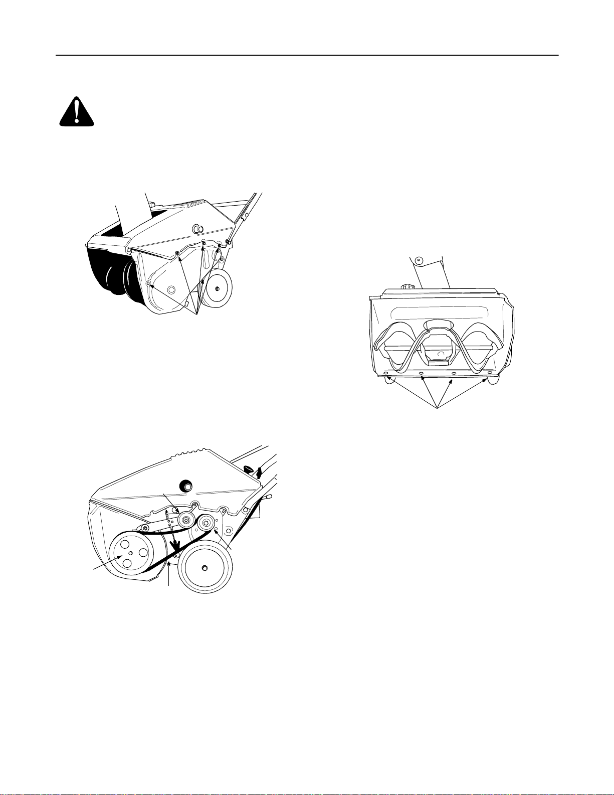
Replacing belt
• Remove the be lt cove r by re moving f ive he x
screws. See Figure 16.
Hex
Screws
Figure 16
• Pull up on the idler pulley and slip the belt off the
engine pulley.
• Push down on the idler pulley and slip the belt off
the auger pulley.
• Reassemble new belt in reverse order.
• Reinstall the belt cover.
Replacing shave plate
The shave pla te is subje ct to wear. It should be
checked periodically. There are two wearing edges
and the shave pl ate can be reverse d. See Figu re 18.
• Remove the four carriage bolts and hex lock nuts
which attach it to the snow thrower housing.
• Install new shave plate, making sure the heads of
the carriage bolts are on the inside of the housing.
• Adjust the shav e plate ac cording t o procedu re in
the “Making A djust ments” section of this manual.
• Tighten securely.
Nuts & Bolts
Auger
Pulley
Idler Pulle y
Figure 17
Belt
Engine
Pulley
Figure 18
Engine
• Refer to the separate engine operator’s manual
packed with your snow thrower for all engine
maintenance procedures.
Fasteners
• Check engine and snow thrower frequently for
loose nuts, bolts, etc., and keep these items
tightened.
10
Page 11

SECTION 7: MAINTENANCE
General Recommendations
• Always observe safety rules when performing any
maintenance.
• The warranty on this snow thrower does not cover
items that have been subjected to operator abuse
or negligence. To receive full value from the
warranty, operator must maintain the snow
thrower as instructed in this manual.
• Changing of engine governed speed will void
engine warranty.
• Some adjustments will have to be made
periodically to maintain your unit properly. All
adjustments in the Making Adjustments section of
this manual should be checked at least once each
season.
Customer Responsibilities
e
s
u
h
c
a
e
MAINTENANCE SCHEDULE
Lubricate pivot points
T
C
Clean snow thrower
U
D
O
Check shave plate adjustment
R
P
Check belt
e
r
o
f
e
B
e
r
e
t
f
A
• Periodically check all fasteners and make sure
these are tight
• Follow the maintenance schedule given below to
get quality performance from your snow thrower
for a long time.
Lubrication
• Lubricate pivot points on the control handle and
the extension spring at the end of the clutch cable
with a light oil once every season and before
storage of the snow thrower at the end of the
season.
s
e
s
u
h
c
a
E
r
u
o
h
5
2
y
r
e
v
O
n
o
s
a
e
s
a
e
c
n
B
e
g
a
r
o
t
s
e
r
o
f
e
SERVICE DATES
E
N
I
Clean engine
G
N
E
Check spark plug
SECTION 8: OFF-SEASON STORAGE
WARNING: Never store engine with fuel
in tank indoors or in enclosed, poorly
ventilated areas where fuel fumes may
reach an open flame, spark or pilot lig ht
as on a furnace, water heater, clothes
dryer, or other gas appliance.
• Clean snow thrower thoroughly.
• Lubricate as instructed above with a light oil.
• Follow “Storage” instructions found in the separate
Engine Operator’s Manual. Preparing the engine
for storage properly is important to prevent
problems ne xt season .
• Store in a clean, dry area. Block the snow thrower
up so it is not resting on the rubber auger blades.
NOTE: Whe n storing an y type of power eq uipment in
an poorly ventilated or metal storage shed, care
should be taken to rustproof the equipment, especially
springs, cables and all moving parts.
11
Page 12

SECTION 9: TROUBLESHOOTING GUIDE
Problem Cause Remedy
Engine fails to start 1. Fuel tank empty, or stale fuel
2. Blocked fuel line
3. Key not in ON posit ion
4. Spark plug wire disconnected
5. Faulty spark plug
6. Gasoline and oil not mixed correctly
Engine runs erratic 1. Unit running on choke
2. Fuel line blocked, or stale fuel
3. Water or dirt in fuel system
4. Carburetor out of adjustment
Engine overheats 1. Gasoline and oil not mixed correctly
2. Carburetor out of adjustment
Loss of power 1. Spark plug wire loose
2. Vent in gas cap plugged
3. Exhaust port plugged.
Excessive vibration 1. Loose parts or damaged auger 1. Stop engine immediately and
Unit fails to propel
itself
Unit fails to
discharge snow
1. Drive cable out of adjustment
2. Drive belt loos e or dama ged
1. Discharge chute clogged
2. Foreign object lodged in auger
3. Drive cable not adjusted properly
4. Drive belt loos e or dama ged
1. Fill tank with clean fresh gasoline/oil
mixture as specifie d in the eng ine
manual.
2. Clean fuel line
3. Insert key and turn to ON position
4. Connect wire to spark plug.
5. Clean spark plug, readjust gap, or
replace.
6. Refer to instructions on fuel mixture in
the engine manual and mix
apprpriately.
1. Move choke lever to OFF position.
2. Clean fuel line and fill tank with fresh,
clean gasoline.
3. Refer to engine manual on remedy.
4. Refer to engine manual; get the
carburetor adjusted by an authorized
service dealer.
1. Drain fuel tank and refill with proper
fuel mix ture.
2. Refer to engine manual; get the
carburetor adjusted by an authorized
service dealer.
1. Connect and tighten spark plug wire.
2. Clear ve nt.
3. Clean port.
disconnect spark plug wire. Check for
possible damage. Tighten all bolts
and nuts. Repair as needed. If the
problem persists, contact a Cub Cadet
dealer.
1. Adjust drive cable following
instructions on snow thrower.
2. Replace drive cable following
instructions on snow thrower.
1. Stop engine immediately and
disconnect spark plug wire. Clean
discharge chute and the auger
housing.
2. Stop engine immediately and
disconnect spark plug wire. Remove
object from auger.
3. Adjust drive cable following
instructions on snow thrower.
4. Replace drive belt following
instructions on snow thrower.
NOTE: For repairs beyond the minor adjustments listed above, call the Customer Dealer Line at 1-800-528-1009 for
the dealer nearest you. Refer to separate engine manual, packed with your snow thrower, for engine information.
12
Page 13
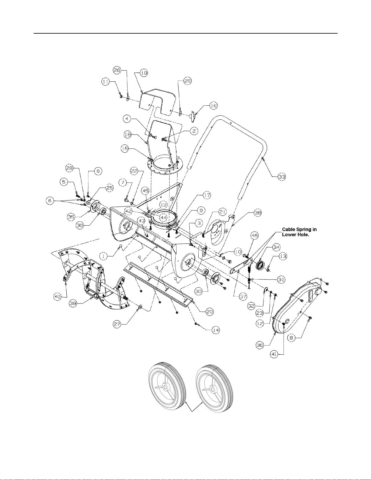
SECTION 10: PARTS LIST FOR MODELS 521R & 521E
13
29
Page 14

Models 521R & 521E
Ref.
No.
1 710-0167 Bolt, Carriage 4
2 710-0276 Bolt, Carriage 1
3 710-0323 Screw, Pan Head 1
4 710-0451 Bolt, Carriage 1
5 710-0642 Screw, Hex Washer 1
6 710-1005 Screw, Hex Washer 6
7 710-0773 Screw, Hex Washer 2
8 710-0896 Screw, Hex Washer 4
9 710-3015 Screw, Hex Cap 6
10 711-0848A Axle 1
11 712-0429 Nut, Hex Center Loc k 1
12 712-3010 Nut, Hex 3
13 712-0116 Nut, Hex Lock 1
15 712-3027 Nut, Hex Lock Fl anged 10
16 720-0284 Knob Assembly 1
17 731-0851A Keeper, Chute 3
18 731-0915B Chute, Lower 1
19 731-0921 Chute, Upper 1
20 731-1033 Shave Plate 1
21 732-0357A Spring, Extension 1
22 736-0108 Washer, Flat 2
23 736-0119 Washer, Lock 1
25 736-0176 Washer, Flat 1
26 736-0159 Washer 2
Part
No. Description Qty.
Ref.
No.
27 736-0326 Washer, Flat 1
28 736-0329 Washer, Lock 1
29 734-1811 Wheel Assembly, Bei ge 2
30 741-0600 Ball Bearing 2
31 746-0910A Cable, Clutch 1
32 748-0234 Spacer, Shoulder 1
33 749-0796 Handle, Lower 1
34 756-0313 Idler, Flat 1
35 784-5174 Cup, Bearing 2
36 784-5176-
37 784-5175B Bracket, Idler/Brake 1
38 684-0114-
39 784-548540 753-0613 Auger Rubber Replacement 1
41 710-0352 Screw, Hex Washer 1
42 784-5720 Bracket, Crank 1
43 710-0451 Screw, Cap 2
44 736-0242 Washer, Bell 2
45 741-0475 Bushing 1
46 710-0459A Screw, Cap 1
Part
No. Description Qty.
Cover, Belt 1
0498
Housing, Blower 1
0498
Auger Ass’y. Comp. 1
0498
14
Page 15

Models 521R & 521E
Ref.
No.
1.
2.
3.
4.
5.
6.
7.
8.
9.
10.
Part
No. Description Qty.
710-1270 Screw, Oval C-Sink L 1
710-0487 Bolt, Carriage 2
712-0324 Nut, Lock Insul. 1
720-0295 Grip Foam 1
720-0284 Knob, Handle 2
725-0157 Tie, Cable 1
736-0451 Washer Saddle 2
746-0883 Control Housing 1
747-0956 Bail 1
749-0711A Handle, Upper 1
Labels (Not Illustrated)
Part
No. Description Qty.
777D03019 Cub 521E 1
777I20393 Instructio n: Control Panel 1
777I20054 Instructio n: Warning Rear Shroud 1
777I20328 Instructio n: Auger Drive 1
777I20335 Instructio n: Chute Crank 1
777S30004 Danger:Shut off eng:Chute 1
777S30008 Danger:Rotating Auger 1
777S30009 Warning:Hot Muffler 1
15
Page 16
Models 521R & 521E
27
10
11
17
21
28
10
2
26
7
25
9
23
14
15
16
13
24
7
22
6
8
3
5
6
20
6
4
3
7
12
19
6
18
1
5
Ref.
No.
1.
2.
3.
4.
5.
6.
7.
8.
9.
10.
11.
12.
13.
14.
Part
No. Description Qty.
684-0054 Dash-21” 1
684-0126 Crank Ass’y Chute 1
710-1003 Screw, Hex 2
710-1005 Screw, Hex 1
710-1090 Flange 4
710-1268 Screw, Hex 8
712-3010 Nut, Hex 6
714-0104 Cotter Pin 1
714-0507 Cotter Pin 1
715-0138 Pin, Roll 2
720-0201A Knob, Chute Crank 1
725-0201 Key, Ignition Switch 1
725-1341B Key, Ignition - Std 1
725-1346 Ignition Switch Nut 1
16
Ref.
No.
15.
16.
17.
18.
19.
20.
21.
22.
23.
24.
25.
26.
27.
28.
Part
No. Description Qty.
725-1347 Ignition Switch Cap 1
725-1425 Ignition Switch 1
726-0100 Cap, Push 1
731-1089A Cover, Choke 1
731-1133B Plug 1
731-2109 Shroud 1
735-0234 Grommet 1
736-0119 Washer, Lock 4
736-0185 Washer, Flat 2
736-0225 Washer, Internal Lock 1
736-0451 Washer 1
747-0697 Eyebolt, Chute Crank 1
747-0737 Upper Chute Crank 1
750-0785 Spacer 1
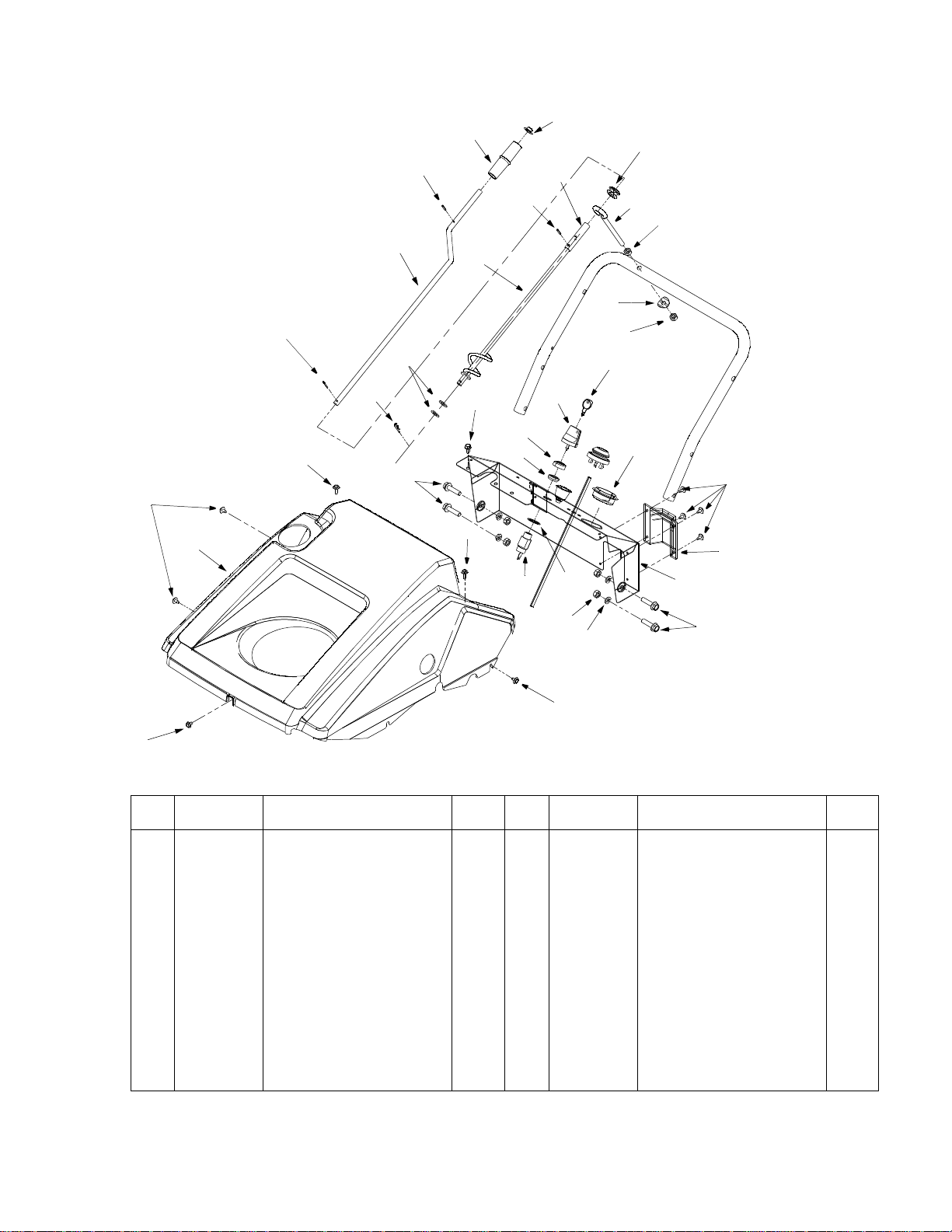
Page 17
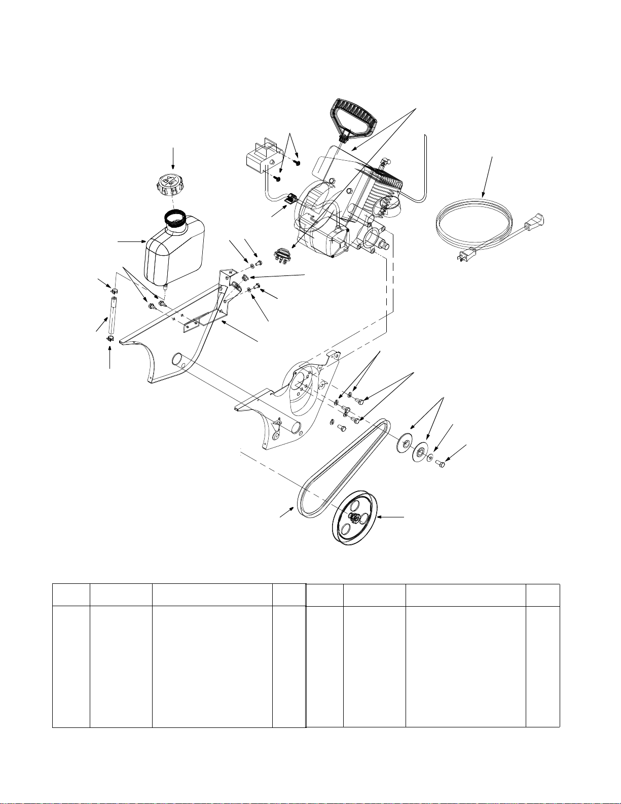
Models 521R & 521E
15
4
9
14
16
12
20
5
1
8
6
13
6
12
2
10
9
Ref.
No.
1.
2.
3.
4.
5.
6.
7.
8.
9.
10.
Part
No. Description Qty.
629-0236 Cord, Extension (521E only) 1
705-5139A Bracket, Gas Tank Support 1
710-0157 Screw, Hex Cap 1
710-0896 Screw, Washer 2
710-1003 Screw, Hex (521E Only) 2
710-3013 Screw, Hex 2
710-3025 Screw, Hex Cap 4
726-0152 Clamp, Mounting 1
726-0205 Clamp, Hose 2
736-0119 Washer, Lock 4
17
7
18
11
3
19
Ref.
No.
11.
12.
13.
14.
15.
16.
17.
18.
19.
Part
No. Description Qty.
736-0242 Washer, Bell 1
736-0329 Washer, Lock 2
741-0475 Bushing 1
751-0535 Hose, Fuel 1
751-0540A Tank, Fuel 1
751-0800 Cap, Fuel 1
754-0101A V, Belt 1
756-0416B V-Pulley, Half 2
756-0475 Pulley 1
17
Page 18

Your Notes Dates
18
Page 19

Your Notes Dates
19
Page 20

MANUFACTURER’S LIMITED WARRANTY FOR:
TWO-YE AR RESIDENTIAL
ONE-YEAR COMMERC IAL
Proper maintenance of your Cub Cadet equipment is the owner’s responsibility . Fo llow the instructions in your
operator’s manual for correct lubricants and maintenance schedule. Your Cub Cadet dealer carries a
complete line of quality lubricants and filters for your equipment’s engine, transmission, chassis and
attachments.
Riding mowers, lawn tractors, garden tractors, Cub Cadet
attachments and home maintenance products
This limited warranty fo r residential u sers, covers any defect in materia ls or workmansh ip in your Cub Cade t
equipment for two years from the da te of purchase for the first us er purchaser. We will r eplace or repair any
part or parts without charge through your authorized Cub Cadet dealer.
Batteries have a one-year prorated limited warranty with 100% replacement during the first three months.
V-belts for either the traction drive or any attachments are covered for one year only.
Cub Cadet equipment used commercially is warranted for one year only.
(Commercial use is defined as either having hired operators or used for income producing purposes.)
Items not covered
The warranty does not co ver ro utin e main tenanc e item s su ch as lubr icant s, fil ters ( oil, fu el, ai r and hydraul ic),
cleaning, tune-ups, br ake and/or clutch inspecti on, adjustments made as par t of normal maintenance, blad e
sharpening, set-up, abuse, accidents and n or mal wea r. It do es not c ov er in ci de ntal co sts such as transp ortin g
your equipment to and from the dealer, telephone charges or renting a product temporarily to replace a
warranted product.
There is no other express warranty.
How to obtain service
Contact your authoriz ed Cu b C adet servicing dealer wh o sol d yo u yo ur Cu b C adet eq ui pme nt. If thi s dea ler is
not available, see the Consumer Yellow Pages under “lawn mowers” for the name of a dealer near you.
If you need further assistance in finding an authorized Cub Cadet servicing dealer, contact:
Cub Cadet Corporation
Post Office Box 368023
Cleveland, Ohio 44136
How does state law ap ply?
This limited warrant y gives y ou speci fic leg al ri ghts, and you may als o have other r ights wh ich var y from stat e
to state.
 Loading...