

Page 1
Operator’s Manual
Single Stage
Snow Thrower
Model 421R
IMPORTANT: Read safety rules and instructions carefully
Warning: This unit is equipped with an internal combustion engine and should not be used on or near any unimproved forest-
covered, brush-covered or grass-covered land unless the engine’s exhaust system is equipped with a spark arrester meeting
applicable local or state laws (if any). If a spark arrester is used, it should be maintained in effe c tive working order by the operator.
In the State of California the above is required by law (Section 4442 of the California Public Resources Code). Other states may have
similar laws. Federal laws apply on federal lands. A spark arrester for the muffler is available through your nearest engine authorized
service dealer or contact the service department, P.O. Box 368023 Cleveland, Ohio 44136-9722.
CUB CADET CORP. P.O. BOX 368023 CLEVELAND, OHIO 44136-9722
PRINTED IN U.S.A.
ECO No. 1405
FORM NO.
770-10005B.fm
(6/2000)
Page 2
TABLE OF CONTENTS
Content Page
Important Safe Operation Practices .................................................................. 3
Assembling Your Snow Thrower....................................................................... 5
Know Your Snow Thrower................................................................................. 7
Operating Your Snow Thrower.......................................................................... 8
Making Adjustments.......................................................................................... 9
Maintaining Your Snow Thrower....................................................................... 10
Off-Season Storage .......................................................................................... 11
Troubleshooting................................................................................................ 12
Parts List........................................................................................................... 13
FINDING MODEL NUMBER
This Operator’s Manual is an important part of your new snow thrower. It will help you to assemble, prepare and
maintain the unit for best performance. Please read and understand what it says.
Before you start assembling your new snow thr ower, ple ase locate t he model pl ate on the
equipment and copy the information from it in the space provided below. The information on the
model plate is very important if you need help from our Customer Support Department or an
authorized dealer.
• You can locate the model number by standing behind the unit in the operating position and looking down at
the dash panel . A sample model plate is explained below. For future reference, please copy the model
number and the serial number of the equipment in the space below.
(Model Number)
(Serial Number)
Copy the model number here:
Copy the serial number here:
CUB CADET CORP.
P.O. BOX 368023
CLEVELAND, OHIO 44136
CALLING CUSTOMER SUPPORT
If you have difficulty assembling this product or have any questions regarding the controls, operation
or maintenance of this unit, please call the Cub Cadet Customer Dealer Referral Line at 1-(800)-528-
1009. Please have your unit’s model number and serial number ready when you call. See previous
section to locate this information. By having the model and serial numbers ready, you help your Cub
Cadet dealer give you faster service.
For more details about your machine, visit our website at www.cubcadet.com
2
Page 3

SECTION 1: IMPORTANT SAFE OPERATION PRACTICES
WARNING: This symbol points out important safety instructions which, if not followed, could endanger the
personal safety and/or property of yourself and others. Read and follow all instructions in this manual before
attempting to operate this machine. Failure to comply with these instructions may result in personal injury. When you
see this symbol— heed its war ning.
WARNING: Engine Exhaust, some of its cons tit uen ts, and certain vehicle components c ontain or emit chemicals
known to State o f Calif ornia to c ause c ancer and bi rth defec ts or othe r reproduct ive harm.
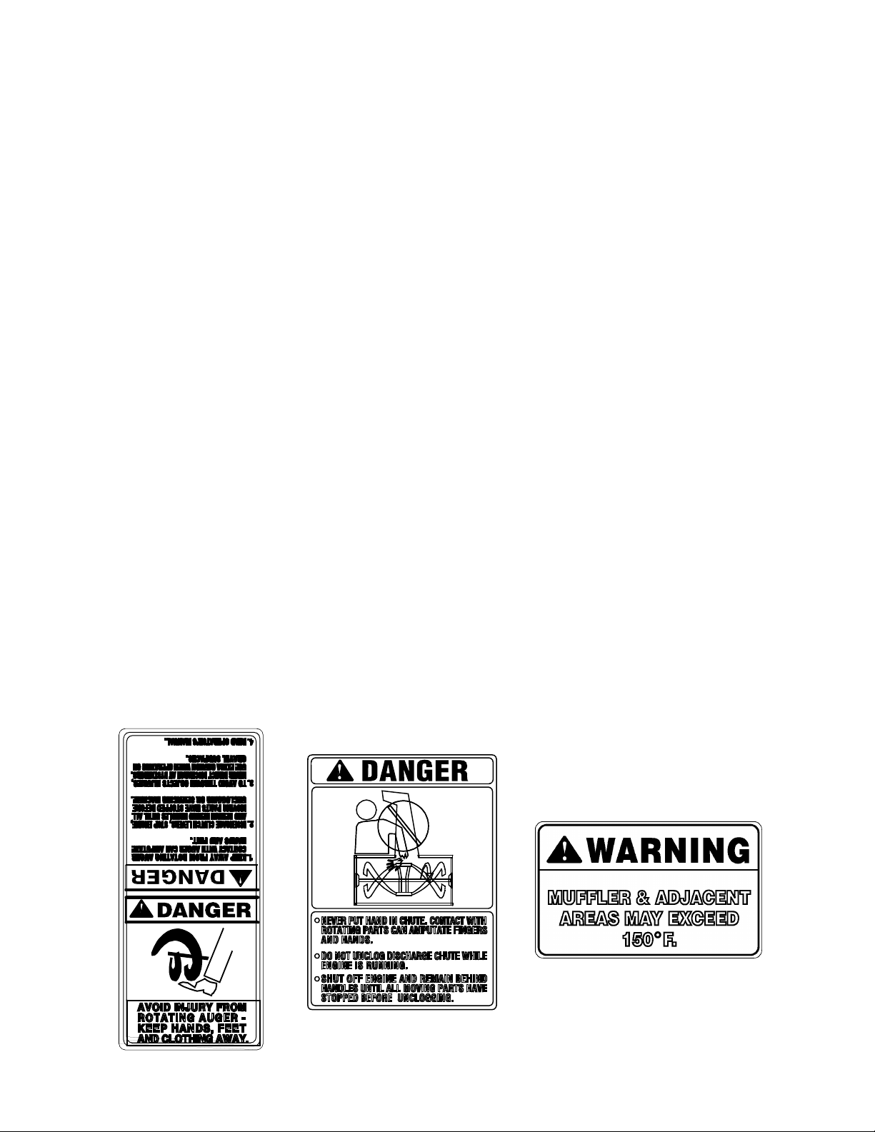
DANGER: This m achine wa s built t o be opera ted acco rding to t he rule s for saf e operatio n in this m anual. As with
any type of power equipmen t, carele ssness or e rror on the part of th e operator can re sult in seri ous inju ry. This
machine is capab le of am putating h ands and feet and throwing objects . Failure to observe t he foll owing saf ety
instructions co uld resul t in seri ous inju ry or death .
Training
1. Read, understand, a nd follow all in struction s on the
machine and in the manual(s ) before a ttempting to
assemble and o perate. Keep this ma nual in a safe pl ace
for future and regular re ference a nd for orde ring
replacement parts.
2. Be familiar with pro per operat ion of al l controls . Know
how to stop the machine and dis engage c ontrols q uickly.
3. Never allow childre n under 14 y ears to o perate thi s
machine. Children 14 years and ove r should read and
understand the op eration in struction s and sa fety rules i n
this manual and should be trained and sup ervised b y a
parent.
4. Never allow adults to operate this machine without
proper instruction.
5. Thrown objects can cause seriou s personal injury . Plan
your snow throwin g pattern to avoid di scharge of mat erial
toward roads, bystanders and the like.
6. Keep bystanders, hel pers, pets and chi ldren at l east 75
feet from the machin e while it is in operatio n. Stop
machine if anyo ne enters the area.
7. Exercise caution to avoid s lipping o r falli ng, espe cially
when operating in reverse.
Preparation
1. Thoroughly inspect the area wh ere the eq uipment i s to
be used. Remove all door mat s, newspa pers, sle ds,
boards, wires and o ther foreig n object s which c ould be
tripped over or throw n by the auger/imp eller.
2. Always wear safet y glasses or eye s hields d uring
operation and while performing an adjustment or repair to
protect your eyes. T hrown ob jects whi ch ricochet can
cause serious inj ury to the eyes.
3. Do not operate wit hout wearing adequate winter outer
garments. Do not wear jewelry, long scarves or other
loose clothing which cou ld becom e entang led in m oving
parts. Wear footwear w hich wi ll improve footing on
slippery surfaces.
4. Use a grounded three wire ex tension cord and receptac le
for all units with electric start engi nes.
5. Adjust collector housing height to clear gravel or crushed
rock surfaces.
6. Disengage all cl utch levers before st arting the engin e.
7. Never attempt to ma ke any adjustme nts whi le engin e is
running, except where spec ifically recomm ended in the
operator’s manual.
8. Let engine and m achine adju st to outd oor tem perature
before starting to clear snow.
9. To avoid personal injury or pro perty damage use extre me
care in handling gasolin e. Gasol ine is e xtremely
flammable and the v apors are explosiv e. Serious
personal injury c an occur w hen gas oline is spilled o n
yourself or your c lothes which c an ignit e. Wash y our skin
and change clot hes immedi ately.
a. Use only an approved gasoline container.
b. Extinguish all cigarettes, cig ars, pipes and other
sources of ignition.
c. Never fuel machine indoo rs.
d. Never remove gas cap or add fue l whil e the
engine is hot or running.
e. Allow engine to cool at leas t two minu tes before
refueling.
f. Never over fill fuel tank. Fil l tank to no more tha n
½ inch below bottom of fill er neck to provide space
for fuel expansi on.
g. Replace gasoli ne cap an d tighten secu rely.
h. If gasoline is sp illed, wip e it off th e engine and
equipment. Move machine to another area . Wait 5
minutes before start ing the e ngine.
i. Never store the machine or fuel containe r inside
where there is an o pen flam e, spark or pilot l ight
(e.g. furnace, water heater, space heate r, clothes
dryer etc.).
j. Allow machine to cool at least 5 mi nutes bef ore
storing.
Operation
1. Do not put hands o r feet near rotating p arts, in the a uger/
impeller housing o r disc harge chu te. Cont act wit h the
rotating parts can am putate ha nds and feet.
2. The auger/impelle r clutch lev er is a safety de vice. Nev er
bypass its operati on. Doing so, makes the ma chine
unsafe and may cause p ersonal i njury.
3. The clutch leve rs must o perate eas ily in both d irections ,
and automatical ly return to the disengaged pos ition when
released.
4. Never operate with a miss ing or da maged di scharge
chute. Keep all safe ty devic es in pl ace and working.
5. Never run an engine indoors or in a poorly ven tilated
area. Engine exhau st conta ins carb on monox ide, an
odorless and dea dly gas .
3
Page 4
6. Do not operate mac hine while under the influenc e of
alcohol or drugs.
7. Muffler and engine beco me hot and can cause a burn. Do
not touch.
8. Exercise extreme ca ution when operating on or cro ssing
gravel surfaces. Stay alert for hidden hazards or traffic.
9. Exercise caution w hen changi ng directi on and w hile
operating on slop es.
10. Plan your snow t hrowing pat tern to av oid disc harge
towards windows, wa lls, cars e tc. To avoid prope rty
damage or personal injury caus ed by a ricochet.
11. Never direct disc harge at c hildren, b ystander s and pet s
or allow anyone in front of t he machi ne.
12. Do not overload machine capa city by attemptin g to clear
snow at too fast of a rate.
13. Never operate this machine without good vi sibility or
light. Always be s ure of yo ur footing and keep a firm hold
on the handles. W alk, never r un.
14. Disengage power to t he aug er/impeller w hen
transporting or not in use.
15. Never operate mach ine at hi gh transp ort speeds on
slippery surfaces. Look down and b ehind an d use ca re
when in reverse.
16. If the machine sh ould start to vi brate abnormally , stop the
engine, disconnect the spark plug an d grou nd it agai nst
the engine. Inspect thoroughly for dam age. Repair any
damage before starting and ope rating.
17. Disengage all cl utch lev ers and st op engin e before y ou
leave the operating position (be hind the handles). Wai t
until the auger/im peller come s to a complete stop befo re
unclogging the d ischarge chute, m aking an y
adjustments, or inspecti ons.
18. Never put your hand in the d ischarge or colle ctor
openings. Always use a cl earing to ol to unc log the
discharge opening.
19. Use only attach ments a nd acce ssories approved by the
manufacturer (e.g. wheel weigh ts, tire c hains, cabs etc.) .
20. If situations occur which are not covered in this manua l,
use care and good judgment. Cont act your dealer or
telephone 1-800-528-10 09 for assistance and the name
of your nearest s ervicing dealer.
Maintenance And Storage
1. Never tamper with sa fety devic es. Check their prop er
operation regularly.
2. Disengage all cl utch lev ers and stop engine. Wait u ntil
the auger/impelle r come to a complet e stop . Disconn ect
the spark plug wir e and ground aga inst the engine to
prevent unintended s tarting before cleaning, r epairing, or
inspecting.
3. Check bolts, and sc rews for pro per tightn ess at fre quent
intervals to keep the machine in sa fe working conditio n.
Also, visually inspect mach ine for an y damage .
4. Do not change the engine governo r setting or over-speed
the engine. The go vernor co ntrols th e maxim um safe
operating speed o f the engi ne.
5. Snow thrower shave plate s and skid shoe s are subjec t to
wear and damage. F or your sa fety prote ction, fre quently
check all compon ents a nd replace with orig inal
equipment manuf acturer’s (O.E.M. ) parts on ly. “Us e of
parts which do not meet the original equipment
specifications ma y lead t o imprope r performan ce and
compromise safety!”
6. Check clutch controls periodically to verify they engage
and disengage proper ly and adjust, if necessary. Re fer to
the adjustment sec tion in th is opera tor’s manual for
instructions.
7. Maintain or replace safety and instruction labels, as
necessary.
8. Observe proper disp osal laws and regu lations for gas,
oil, etc. to protect t he enviro nment.
9. Prior to storing, run machine a few minutes to clear snow
from machine an d prevent freeze up of auger/i mpeller.
10. Never store the machine or fuel cont ainer inside whe re
there is an open flame, s park or pilot light such as a water
heater, furnace ,cloth es dryer etc.
11. Always refer to the o perator’s manual f or prope r
instructions on off-sea son storage.
Your Responsibility:
• Restrict the use of this powe r machine to persons who
read, understand a nd follow the warning s and
instructions in this ma nual and on the ma chine .
4
Page 5
SECTION 2: ASSEMBLING YOUR SNOW THROWER
Unpacking From Carton
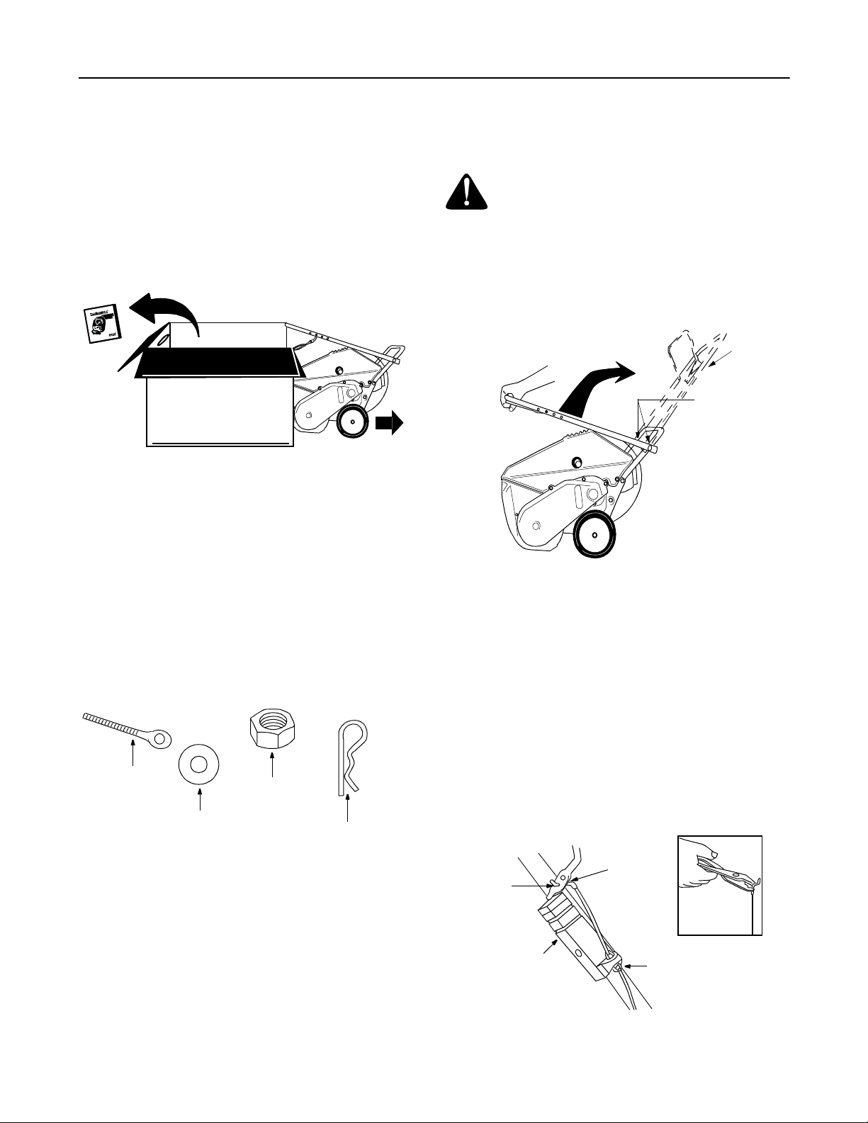
• Cut along corners of the carton and lay it down flat.
See Figure 1. Remove packing material.
• Remove any loose parts included with unit (i.e.,
operator’s manual, etc.).
• Roll unit out of carton. Check carton thoroughly for
any remaining loose part.
Remove loose parts
Roll unit out
Figure 1
Hardware Pack
1. Ignition Keys* (2)
*One key may be in the switch on snow thrower.
(Items 2 to 5 are illustrated in Figure 2.)
2. Eyebolt
3. Saddle Washer 5/16" I.D.
4. Hex Nuts 5/16-18 Thread (2)
5. Cotter Pin
Eye Bolt
Saddle
Wash er
Hex Nut
Cotter Pin
Before Assembly
WARNING: Disconnect the sp ark plug wire
and ground it against the engine to prevent
unintended starting.
Raising Upper Handle
• Loosen the hand knob on each side of the handle.
Remove packing material, if any.
Raise
handle
to here
Hand Knob
Figure 3
• Raise the upper handle in the direction shown in
Figure 3 till it clicks into the operating position.
Make sure not to pinch or crimp the cable.
• Tighten the hand knobs.
Attaching Control Cable
The control cable may already be attached to the
control handle. If not attached, complete the following
steps to attach it to the snow thrower housing.
• Route the control cable over the lower handle.
Insert the end of the cable into the hole in the
control housing as shown in Figure 4. Push the
plastic fitting until it locks into the control housing.
Figure 2: Hardware Pack
Items Required F or Assembly
1. Pair of pliers (not necessary, but helpful)
2. Two cycle engine oil (included)
3. Fresh gasoline
NOTE: All refere nces to left or right side of the snow
thrower is from the operating position only.
Bottom
Hole In
Control
Handle
Control
Housing
5
“Z” End
of Cable
Figure 4
Plastic
Fitting
Page 6
• Lift the control handle up, and hook the “Z” end of
the contro l cable i nto th e bottom hole in the control
handle, from the outside to the inside . If necessary,
pull up on the end of the cable with a pair of pliers to
obtain slac k in order to ho ok it into the control
handle. Hold the “Z” fitting with the pliers, not the
cable, to avoid damaging the cable.
NOTE: The upper hole in th e control handle provides
for adjustment in belt tension. Refer to page 9 of this
manual for instructions.
Installing Chute Crank
• Thread one 5/16” hex nut all the way onto the
eyebolt. See Figure 5. All necessary hardware is
included in the hardware pack shipped with your
unit. See Figure 2 for more details.
• Slide the eyebolt onto the chute crank. Insert
eyebolt into the hole in the lower handle.
Chute Crank
Eye Bolt
• Secure eyebolt with 5/16” saddle washer and hex
nut. The cupped side of washer goes against the
handle. Adjust lower hex nut until the eyebolt is
positioned so that the chute crank turns freely
(does not bind).
• Move upper hex nut down against the lower handle.
Tighten lower hex nut securely.
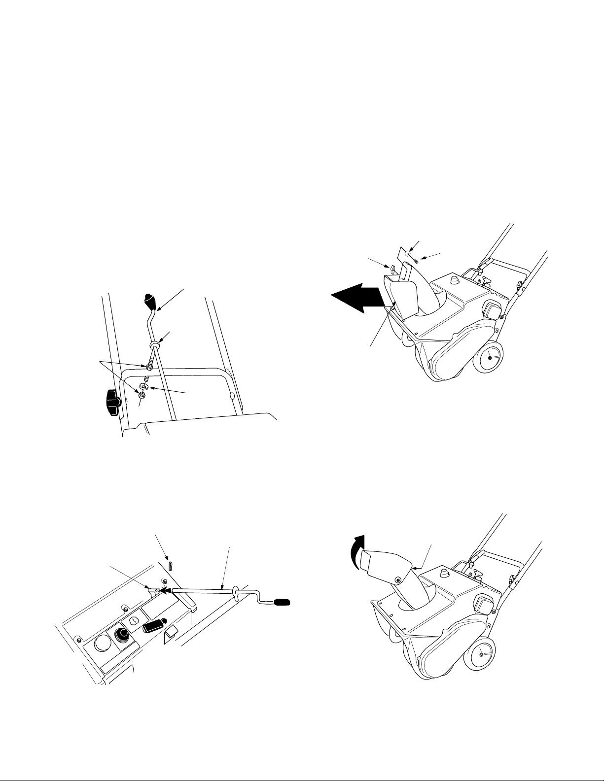
Assembling Discharge Ch ute
The snow thrower has been shipped with the upper
chute pivoted all the way down. Assemble as follows:
• Turn the chute crank until the chute faces straight
to the front. See Figure 7.
Flat
Hand
Knob
Front
Washer
Carriage
Bolt
Hex
Nuts
Saddle
Wash er
Figure 5
• Insert the chute crank into the coupler at the top
right side of the snow thrower. See Figure 6.
• Rotate the crank to align holes, and insert the cotter
pin. Bend ends of cotter pin in opposite directions to
secure. See Figure 6.
Cotter Pin
Chute Crank
Coupler
Upper
Chute
Figure 7
• Remove the hand knob, flat washer and carriage
bolt from the upper chute. See Figure 7.
• Pivot the upper chute up so that there is no gap
between the upper and the lower chute. See Figure
8. Secure with hardware just removed.
No
Gap
Pivot
upper
chute
Figure 6
Figure 8
6
Page 7

SECTION 3: KNOW YOUR SNOW THROWER
Be familiar with all the controls and their proper operation. Know how to stop the machine and disengage
them quickly.
• Compare Figure 9 with the controls on your snow thrower before starting the machine or trying to operate it.
Discharge
Chute
Chute Crank
Shave
Plate
Auger Control
Handle
Auger
Upper
Handle
Spark
Plug
Cover
Primer
Button
Choke Lever
Off
On
Ignition
Key
Starter
Handle
Figure 9
Choke Lever
Place choke lever in “ON” position to start a cold
engine.
Primer Button
Used to inject fuel directly into the carburetor to insure
fast starts in cold weather. Follow engine manual to
prime engine.
Ignition Key
Used to start engine. Put key in “ON” position to start.
Starter Handle
Used to manually start the engine.
Spark Plug Cover
Spark plug located under the cover.
Auger Control Handle
Located on the upper handle, the auger control handle
is used to engage and disengage the augers. The snow
thrower is designed to be propelled by the rotation of
the augers. Pull the control handle back against the
upper handle to engage the augers; release to
disengage.
Chute Crank
Located on right side of dash panel, the chute crank
determines the direction that snow will be discharged.
Turn clockwise to discharge snow to the left; turn
counterclockwise to discharge to the right.
Discharge Chute
The angle of the discharge chute controls the distance
that the snow is thrown. Tilt the discharge chute up for
greater distance; tilt down for less distance. Loosen the
hand knob on the side of the discharge chute to adjust.
Tilt the chute to the desired position, and tighten the
knob.
Stopping Engine
• Turn ignition key to OFF position and remove it
from the snow thrower.
7
Page 8

SECTION 4: OPERATING YOUR SNOW THROWER
Before Starting
WARNING: Read, understand, and follow
all instructions an d warnings on the machine
and in this manual before operating.
• The spark plug wire was disconnected for safety
purposes during assembly. Attach spark plug wire
to spark plug before starting.
Fuel & Oil Mixture
WARNING: Use extreme care when
handling gasoline. Gasoline is extremely
flammable and the vapors are explosive.
Never fuel machine indoors or while the
engine is hot or running. Extinguish cigarettes,
cigars, pipes and other sources of ignition.
Your snow thrower uses a two cycle engine that
requires a mixture of gasoline and two cycle engine
oil. Refer to the engine operator’s manua l for proper oil
and fuel recommendations.
• A plas tic cup was provided inside the fuel fill
opening on the fuel tank. Remove and discard this
cup before filling up the tank. Use the seperate fuel
tank cap to close after fill-up.
Starting Engine
• To start the engine of your snow thrower, follow the
engine manual.
Operating Snow Thrower
r
e
t
e
a
c
e
r
n
a
G
t
s
i
D
s
e
s
c
e
n
L
a
t
s
i
D
Hand
Knob
Figure 10
• Adjust the upper discharge chute up or down as
shown in Figure 10. Then use the chute crank to
position the discharge chute in order to discharge
snow with the wind.
Upper
Discharge
Chute
• After making sure no bystanders or obstacles are in
front of the unit, engage the auger control handle.
See Figure 11. As the snow thrower starts to move,
maintain a firm hold on the handle, and guide the
snow thrower along the path to be cleared.
• Release the auger control handle to stop the snow
throwing action and the forward motion.
Press auger
control handle
to engage
auger
Turn handle
to change
discharge
direction
Figure 11
Stopping Engine
• Run the engine for a few minutes before stopping to
help dry any moisture on the engine.
• To stop engine: Turn ignition key to OFF position
and remove it from the snow thrower.
IMPORT ANT :
Engine will not start without it.
• Wipe all snow and moisture from the unit. Move the
choke lever back and forth several times and leave
it in the ON position.
Keep the ignition key in a safe place.
Operating Tips
• Discharge snow downwind whenever possible.
Slightly overlap each previously cleared path.
• Lifting up on the handle will allow the rubber on the
augers to propel the snow thrower forward. Pushing
downward on the handle will raise the augers off
the ground and stop the forward motion.
NOTE: Excessive upward pressure on the handle will
result in premature wear on the rubber auger blades
which would not be covered by warranty.
• Run the engine for a few minutes before stopping to
help dry any moisture on the engine.
• Clean the snow thrower thoroughly after each use.
WARNING: Muffler, engine and surrounding
areas become hot and ca n cause a burn. Do
not touch.
8
Page 9

SECTION 5: MAKING ADJUSTMENTS
WARNING: NEVER attempt to make any
adjustments while the eng ine is running, except
where specified i n the ope rator’s manual .
Shave Plate
• To check the adjustment of the shave plate, place
the unit on a leve l surface. See Figure 12. The
wheels, shave plate and augers should all contact
level surface. Note that if the shave plate is
adjusted too high, snow may blow under the
housing. If the shave plate wears out excessively,
or the unit will not self-propel, the shave plate may
be adjusted too low.
NOTE: On new units or units with a new shave plate
installed, the augers may be slightly off the ground.
Augers
• To adjust, tip the snow thrower back so that it rests
on the handle. Loosen the lock nuts and bolts which
secure the shave plate to the housing. See Figure
13. Move the shave plate to desired position and
retighten the nuts and bolts. Make certain all nuts
and bolts are tightened securely.
Shave Plate
Figure 12
Wheels
Belt Tension
Periodic adjustment of the belt tension may be required
due to normal stretch and wear on the belt. If augers
hesitate while turning although engine maintains same
speed, adjust tension following instructions below.
• The upper hole in the control handle provides
adjustment for belt tension. To adjust, disconnect
the “Z” end of control cable from the bottom hole in
the control handle. See Figure 14 . Hook the cable
into the upper hole in control handle as shown here.
Upper
Hole
Clutch
Cable
Control
Housing
Figure 14
If additional adjustment is required, follow steps below.
• Remove the belt cover by removing five hex screws
that hold it in place. See Figure 16.
• There are three adjustment holes provided in the
idler bracket assembly. See Figure 15. To adjust,
move the extension spring on the end of the clutch
cable to the next higher adjustment position on the
idler bracket assembly. Reassemble belt cover.
High Position
Idler
Bracket
Middle Position
Spring on
End of Clutch
Auger
Pulley
Low Position
Cable
Nuts & Bolts
Figure 13
Figure 15
Carburetor
WARNING: If any adjustments need to be
made to the engine while the engine is running
(e.g. carburetor), keep clear of all moving
parts. Be careful of muffler, engine and other
surrounding heated surfaces.
• Refer to the separate engine manual, packed with
your unit, for carburetor adjustment information.
9
Page 10

SECTION 6: MAINTAINING YOUR SNOW THROWER
WARNING: Before servici ng, repairing, or
inspecting, disengage all clutch levers and
stop engine. Wait until all moving parts have
come to a complete stop. Disconnect spark
plug wire and ground it aga inst the engi ne to
prevent unintended starting.
General Recommendations
• Always observe safety rules when performing any
maintenance.
• All adjustments explained on page 9 should be
checked at least once each season.
• Periodically check all fasteners and make sure
these are t ight
• Follow the maintenance schedule given below to
get quality performance from your snow thrower for
a long time.
Replacing Belt
• Remove t he belt cover b y remo ving fi ve hex
screws. See Figure 16.
Belt Cover
Figure 16
Hex
Screws
• Pull up on the idler pulley and slip the belt off the
engine pulley.
• Push down on the idler pulley and slip the belt off
the auger pulley.
• Reassemble new belt. See Figure 17.
• Reinstall the belt cover.
Idler Pull ey
Engine
Auger
Pulley
Pulley
Belt
Figure 17
Replacing Sha ve Plate
The shave plate is subject to wear. It should be
checked periodically. There are two wearing edges and
the shave plate can be reversed. See Figure 13.
• Remove the four carriage bolts and hex lock nuts
which attach it to the snow thrower housing.
• Install new shave plate, making sure the heads of
the carriage bolts are on the inside of the housing.
• Adjust the shave plate according to procedure in
the “Making Adjustments” section of this manu al.
• Tighten securely.
Customer Responsibilities
MAINTENANCE SCHEDULE
T
Lubricate pivot points
C
U
Clean snow throwe r
D
O
Check shave plate
R
P
Check belt
E
N
I
Clean engine
G
N
E
Check spark plug
e
s
u
h
c
a
e
e
r
o
f
e
B
s
u
h
c
a
e
r
e
t
f
A
s
n
r
e
u
o
a
h
e
5
s
2
a
y
r
e
e
c
v
n
E
O
e
o
g
s
a
r
o
t
s
e
r
o
f
e
B
SERVICE DATES
10
Page 11

Lubrication
• Lubricate pivot points on the control handle and the
extension spring at the end of the clutch cable with
a light oil once every season and before storage of
the snow thrower at the end of the season.
SECTION 7: OFF-SEASON STORAGE
Engine
• Refer to the separate engine operator’s manual
packed with your snow thrower for all engine
maintenance procedures.
• Check engine and snow thrower frequently for
loose hardware, and tighten as needed.
WARNING: Never store engine with fuel in
tank indoors or in enclos ed, poor ly ven tilated
areas where fuel fumes may reach an open
flame, spark or pilot light as on a furnace,
water heater, clothes dryer, or other gas
appliance.
• Clean snow thrower thoroughly.
• Lubricate as instructed above with a light oil.
• Follow “Storage” instructions in the Engine Manual.
• Store in a clean, dry area. Block the snow thrower
up so it is not resting on the rubber auger blades.
NOTE: When storing any type of power equipment in
an poorly ventilated or metal storage shed, care should
be taken to rustproof the equipment, especially springs,
cables and all moving parts.
11
Page 12

SECTION 8: TROUBLESHOOTING GUIDE
Problem Cause Remedy
Engine fails to star t 1. Fuel tank empty, o r stale fuel
2. Blocked fuel lin e
3. Key not in ON position
4. Spark plug wire disconnected
5. Faulty spark plug
6. Gasoline and oil not mix ed corr ectly
Engine runs erratic 1. Unit running on choke
2. Fuel line blocked , or sta le fuel
3. Water or dirt in fuel system
4. Carburetor out of adjustment
Engine overheats 1. Gasoline and oil not mix ed correct ly
2. Carburetor out of adjustment
Loss of power 1. Spark plug wire loose
2. Vent in gas cap plu gged
3. Exhaust port plugged .
Excessive vibration 1. Loose parts or da maged au ger 1. Stop engine imme diately and disc onnect
Unit fails to self-p ropel 1. Drive cable out of ad justment
2. Drive belt loose or damage d
Unit fails to discharge
snow
1. Discharge chute clogged
2. Foreign object lodged in aug er
3. Drive cable not adjusted properly
4. Drive belt loose or damage d
1. Fill tank with clean fresh gasoline/oil
mixture as specif ied in th e engi ne manua l.
2. Clean fuel line
3. Insert key and turn to ON pos ition
4. Connect wire to spark plug.
5. Clean spark plug, readjust gap, or replace.
6. Refer to engine manual
1. Move choke lever to off position.
2. Clean fuel line and fill tank with fresh,
clean gasoline.
3. Refer to engine manual o n remedy .
4. Refer to engine manual.
1. Drain fuel tank an d refill wi th proper fu el
mixture.
2. Refer to engine manual.
1. Connect and tighten spark plug wire.
2. Clear vent.
3. Clean port.
spark plug wire. Check for possible
damage. Tighten all bolts and nuts. Repair
as needed. If the problem persists, take
unit to an authori zed servic e dealer.
1. Adjust drive cabl e following instructi ons on
snow thrower.
2. Replace drive cable follo wing instruct ions
on snow thrower.
1. Stop engine imme diately and disc onnect
spark plug wir e. Clean discharge chute
and the auger housing.
2. Stop engine imme diately and disc onnect
spark plug wire. Remove object .
3. Adjust drive cabl e following instructi ons on
snow thrower.
4. Replace drive belt followin g instructions
on snow thrower.
NOTE: For repairs beyond the minor adjustments listed above, call the Customer Dealer Line at 1-800-528-1009 for
the dealer nearest you. Refer to separate engine manual, packed with your snow thrower, for engine information.
12
Page 13

SECTION 9: PARTS LIST FOR MODEL 421R
9
10
4
7
3
8
6
1
4
7
5
2
Ref. No. Part No. Description
710-0487 Carriage Screw
1.
710-1270 Oval C-Sunk Machine Screw
2.
712-0324 Hex Lock Nut
3.
720-0284 Wing Nut
4.
720-0295 Foam Grip: Handl e
5.
725-0157 Cable Tie
6.
736-0451 Saddle Washer
7.
746-0883 Cable Housing w/o Throt tle
8.
747-0956 Auger Bail: Gull Win g
9.
749-0711A Upper Hand le: Gull Wing
10.
NOTE: For painted parts, please refer to
the list of color codes below. Please add the
applicable color code, wherever needed, to
the part number to order a replacement part.
For instance, if a part, numbered 700-xxxx,
is painted Cub Yellow , the part number to
order would be 700-xxx x-0716.
Cub Yellow: 0716
Cub Beige: 0499
Cub Blue: 0685
Powder Black: 0637
13
Page 14

SECTION 10: Model 421R
11
28
5
6
25
35
6
7
22
30
19
26
26
2
4
18
17
9
15
4542
13
44
16
21
33
38
40
39
22
10
1
27
3
30
20
14
7
35
6
36
46
37
41
31
32
34
13
23
12
8
14
Page 15

Model 421R
Ref. No. Part No. Part Description
1.
2.
3.
4.
5.
6.
7.
8.
9.
10.
11.
12.
13.
15.
16.
17.
18.
19.
20.
21.
22.
23.
710-0167 Carriage Bolt
710-0276 Carriage Bolt
710-0323 Pan Head Screw
710-0451 Carriage Bolt
710-0642 Hex Washer Screw
710-1005 Hex Washer Screw
710-0773 Hex Washer Screw
710-0896 Hex Washer Screw
710-3015 Hex Cap Screw
711-0848A Axle
712-0429 Hex Center Lock Nut
712-3010 Hex Nut
712-0116 Hex Lock Nut
712-3027 Hex Lock Flanged Nut
720-0284 Knob
731-0851A Chute Keeper
731-0915B Lower Chute
731-0921 Upper Chute
731-1033 Shave Plate
732-0357A Extension Spring
736-0108 Flat Washer
736-0119 Lock Washer
Ref. No. Part No. Part Description
25.
26.
27.
28.
30.
31.
32.
33.
34.
35.
36.
37.
38.
39.
40.
41.
42.
43.
44.
45.
46.
736-0176 Flat Washer
736-0159 Washer
736-0326 Flat Washer
736-0329 Lock Washer
741-0600 Ball Bearing
746-0910A Cable—Clutch
748-0234 Spacer
749-0796 Handle—Lower
756-0313 Flat Idler
784-5174 Bearing Cup
784-5176 Cover—Belt
784-5175B Idler/Brake Bracket
684-0114 Blower Housing
784-5485 Auger Ass’y. Comp.
753-0613 Auger Rubber Replacem ent
710-0352 Hex Washer Screw
784-5720 Crank Bracket
710-0451 Cap Screw
736-0242 Bell Washer
741-0475 Bushing
710-0191 Hex Screw
1
Ref. No. Part No. Description
1 734-1811 Wheel Assembly: 7 x 1.7”
NOTE: For painted part s, please refer to the list of color codes below. Please add the applicable color code, wherever
needed, to the part number to order a replacement part. For instance, if a part, numbered 700-xxxx, is painted Cub
Yellow, the part number to order would be 700-xxxx-0716.
Cub Yellow: 0716
Cub Beige: 0499
Cub Blue: 0685
Powder Black: 0637
15
Page 16

Model 421R
11
10
28
17
21
26
7
25
7
13
19
18
22
2
6
15
14
24
7
16
27
9
23
8
29
4
3
5
20
5
16
Page 17

Model 421R
Ref. No. Part No. Part Description
684-0054A Dash Assembly
1.
684-0126 Chute Crank Assembly
2.
710-1003 Special Screw: 310-16 x 0.375”
3.
710-1090 Hex Flange Screw 5/16-18 x 1.25”
4.
710-1268 Special screw
5.
710-1652 Self-Tapping Screw 1/4-20 x .625”
6.
712-3010 Hex Nut 5/16-18
7.
714-0104 Hairpin Clip
8.
714-0507 Cotter Pin
9.
715-0138 Roll Pin
10.
720-0201A Chute Crank Knob
11.
725-0201 Ignition Key
12.
725-1341B Ignition Key w/o Logo
13.
725-1346 Ignition Switch Nut
14.
725-1347 Ignition Switch Cap
15.
725-1425 Switch: Key, Recoil Start
16.
726-0100 Push Cap
17.
731-1089A Choke Cover
18.
731-1133B Spilling Cup
19.
731-2109 Shroud: 21” Beige
20.
735-0234 Rubber Grommet
21.
736-0119 Lock Washer
22.
736-0185 Flat Washer
23.
736-0225 Internal Lock Washer
24.
736-0451 Saddle Washer
25.
747-0697 Eyebolt
26.
747-0737 Upper Chute Crank
27.
750-0785 Spacer
28.
7510009636 Mitten Grip Handle
29.
NOTE: For painted parts, please refer to
the list of color codes below. Please add the
applicable color code, wherever needed, to
the part number to order a replacement part.
For instance, if a part, numbered 700-xxxx,
is painted Cub Yellow, the part number to
order would be 700-xxxx-0716.
Cub Yellow: 0716
Cub Beige: 0499
Cub Blue: 0685
Powder Black: 0637
17
Page 18

Model 421R
6
3
12
6
14
7
13
4
10
11
4
10
1
15
17
8
5
5
8
16
9
2
Ref. No Part No. Description
705-5139A Support Bracket: Gas Tank
1.
710-0157 Hex Bolt 5/16-24 x .75”
2.
710-1652 Self-Tapping Screw
3.
710-3013 Hex Screw 1/4-20 x .50”
4.
710-3025 Hex Screw
5.
726-0205 Hose Clamp
6.
731-2113A Cup
7.
736-0119 Lock Washer
8.
736-0242 Beleville Washer
9.
736-0329 Lock Washer
10.
741-0475 Plastic Bushing
11.
751-0535 Fuel Line Hose
12.
751-0540A Fuel Tank: 2 Quart
13.
751-0800 Fuel Cap
14.
754-0101A V-Belt
15.
756-0416B V-Pulley Half
16.
756-0475 V-Pulley Half
17.
NOTE: For painted parts, please refer to the list of color codes below. Please
add the applicable color code, wherever needed, to the part number to order a
replacement part. For instance, if a part, numbered 700-xxxx, is painted Cub
Yellow, the part number to order would be 700-xxxx-0716.
Cub Yellow: 0716
Cub Beige: 0499
Cub Blue: 0685
Powder Black: 0637
18
Page 19

Model 421R
19
Page 20

MANUFACTURER’S LIMITED WARRANTY FOR:
TWO-YEAR RESIDENTIAL
ONE-YEAR COMMERCIAL
Proper maintenance of your Cub Cad et equi pm ent is the own er’s responsibility. Follow the instructions in your
operator’s manual for correct lubricants and maintenance schedule. Your Cub Cadet dealer carries a
complete line of quality lubricants and filters for your equipment’s engine, transmission, chassis and
attachments.
Riding mowers, lawn tractors, garden tractors, Cub Cadet
attachments and home maintenance products
This limited warra nty for residential users, covers a ny defect in mater ials or workmansh ip in your Cub Cadet
equipment for two years from the dat e of purchase for the firs t user purchase r. We will replace or repa ir any
part or parts without charge through your authorized Cub Cadet dealer.
Batteries have a one-year prorated limited warranty with 100% replacement during the first three months.
V-belts for either the traction drive or any attachments are covered for one year only.
Cub Cadet equipment used commercially is warranted for one year only.
(Commercial use is defined as either having hired operators or used for income producing purposes.)
Items not covered
The warranty doe s not c over rout ine ma intena nce i tems suc h as lubri cants, f ilt ers (o il, fue l, air a nd h ydraul ic),
cleaning, tune-ups, br ake and/or clutch inspection, a djustments made as part of normal maintenance, blade
sharpening, set-up, a bus e, a ccid ent s and normal wear. It doe s n ot c over in ci den tal cos ts suc h as trans po rti ng
your equipment to and from the dealer, telephone charges or renting a product temporarily to replace a
warranted product.
There is no other express warranty.
How to obtain service
Contact your autho riz ed Cub Ca det s ervi cing de ale r who s old you your Cub Ca det eq uip men t. I f th is d eal er i s
not available, see the Consumer Yellow Pages under “lawn mowers” for the name of a dealer near you.
If you need further assistance in finding an authorized Cub Cadet servicing dealer, contact:
Cub Cadet Corporation
Post Office Box 368023
Cleveland, Ohio 44136
How does state law apply?
This limited warranty gi ves y ou spec ific lega l rig hts, and you m ay als o have ot her right s which va ry from s tate
to state.
 Loading...