

Page 1

www.mymowerparts.com
Service Manual
4x2 Utility Vehicle
Poly Bed and Steel Bed
NOTE: These materials are prepared for use by trained technicians who are experienced in the service and repair of equipment of the
kind described in this publication, and are not intended for use by untrained or inexperienced individuals. Such individuals should seek
the assistance of an authorized service technician or dealer. Read, understand, and follow all directions when working on this equipment. This includes the contents of the Operators Manual, which came with your equipment. No liability can be accepted for any inaccuracies or omission in this publication, although every care has been take to make it as complete and accurate as possible. The right
is reserved to make changes at any time to this document without prior notice and without incurring an obligation to make such
changes to previously published documents. All information contained in this publication is based on product information available at
the time of publication. Photographs and illustrations used in this publication are for reference use only and may not depict actual
model and component parts.
MTD Products Inc. - Product Training and Education Department
FORM NUMBER - 769-01635
12/2004
K&T Saw Shop 606-678-9623 or 606-561-4983
Page 2

www.mymowerparts.com
K&T Saw Shop 606-678-9623 or 606-561-4983
Page 3

www.mymowerparts.com
TABLE OF CONTENTS
Poly Bed 4 X 2 Drive System
Customer Responsibilities ............................................................................................ 1
Gear Lube .....................................................................................................................1
Diagnosis: Confirming Transaxle Fault .........................................................................3
Transmission Linkages ................................................................................................. 3
Diagnosis and Service: Drive Belt and Clutches
(CVT or Continuously Variable Transmission) ...................................................11
Transaxle Removal and Replacement ........................................................................20
Transaxle Installation Notes: .......................................................................................24
Link Assembly .............................................................................................................25
Transaxle Repairs .......................................................................................................26
Poly Bed 4 X 2 Brake System
Maintnance and Description of the Brake System ...................................................... 39
Complete Inspection (Drum and Shoe Removal) ......................................................40
Brake Adjustment (under the hood) 43
4 X 2 Drive System - (Steel Bed)
Customer Responsibilities .......................................................................................... 47
Gear Lube ...................................................................................................................47
Diagnosis: Confirming Transaxle Fault .......................................................................48
Diagnosis and Service: Drive Belt and Clutches
(CVTor Continuously Variable Transmission) ......................................................49
CVT Removal: Driven Pulley ......................................................................................52
CVT Removal: Driving Pulley ......................................................................................53
Transaxle Removal and Replacement ........................................................................55
Transaxle Installation Notes: .......................................................................................59
Link Assembly .............................................................................................................60
Transaxle Orientation ..................................................................................................61
Transaxle Disassembly: Axle tube Removal and Case Separation ............................ 62
Transaxle Disassembly: Gear Set Removal and Disassembly ................................... 64
Transaxle Disassembly: Differential ............................................................................68
Transaxle: Axle Tubes ................................................................................................70
In-cradle Engine Service .............................................................................................74
K&T Saw Shop 606-678-9623 or 606-561-4983
Page 4

www.mymowerparts.com
K&T Saw Shop 606-678-9623 or 606-561-4983
Page 5
www.mymowerparts.com
Poly Bed 4 X 2 Drive System
Poly Bed 4 X 2 Drive System
ABOUT THIS SECTION:
This section covers the drive system and transaxle
used in the Big Country utility vehicle model series 414
(37AN414J710). This model is distinguished from the
420 and 430 series by a polymer bed and the use of a
different drive system. The 420 and 430 series use a
Honda 18 hp. V-twin engine and a Dana transaxle.
The 414 uses a drive system manufactured by
Kawasaki.
1. CUSTOMER RESPONSIBILITIES
• Housing, axle, bearing, or axle tube damage
caused by impact or over-loading constitutes
customer abuse, and is not covered under the
warranty. The poly bed Big Country has a lower
load rating than the steel bed version: 900 Lb.
(410 KG) including bed load, operator, and passenger.
• Damaged caused by shock-loading the transmission is not covered under the warranty.
Shock-loading is primarily caused by shifting
between forward and reverse gears without
allowing the vehicle to come to a full stop. This is
possible if the vehicle is operated abusively
2. GEAR LUBE
2.1. Service intervals: Initial change: 50 hours
Subsequent changes: 500 hours of 2 years
Check level: every 100 hours.
2.2. The transaxle should contain 68 fluid ounces
(2.0 L) API “GL-5” hypoid gear lube.
• SAE 90 weight above 41deg. f. (5 deg. C.)
• SAE 80 weight below 41 deg. f. (5 deg. C.)
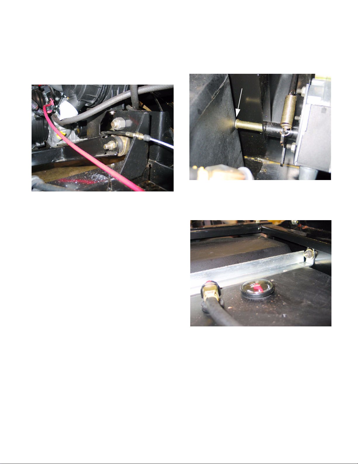
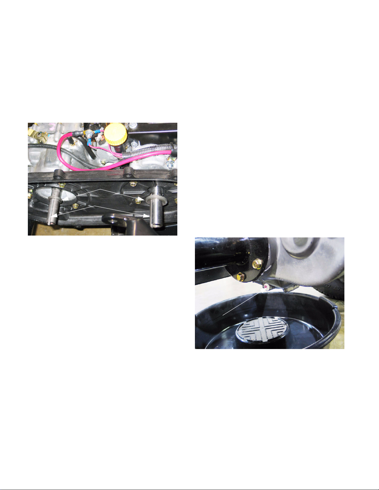
2.3. To check the gear lube level, park the vehicle
on a flat level surface.
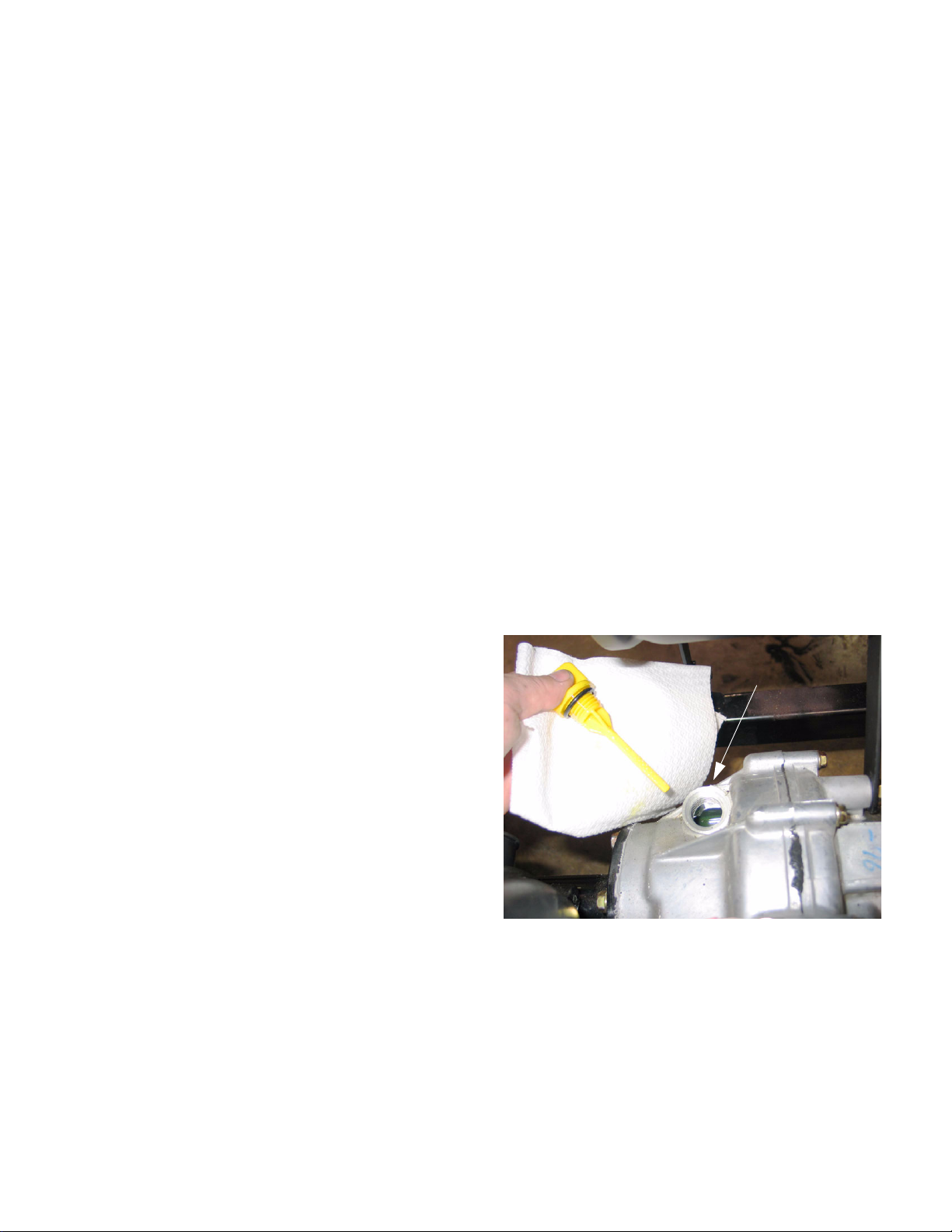
2.4. Clean the area around the oil fill cap/dipstick
near the back of the transaxle housing and
remove the dipstick.
2.5. Wipe the dipstick clean, insert it back into the
threaded hole, but do not thread it in.
2.6. Withdraw the dipstick and check the oil level. It
should be between the upper and lower level
lines. The area between the lines is marked with
cross-hatch. See Figure 2.6.
• Damage caused by a lubrication failure is not
covered under the warranty.
• It is the customer’s responsibility to have any
leaks repaired in a timely fashion.
• The lug nuts should be inspected for looseness
after the first ten hours of operation. Lug nuts
should be tightened to a torque of 55-60 ft.-lbs.
• The brakes are not self-adjusting. It is the customer’s responsibility to maintain them in good
working order and proper adjustment, whether
directly or through an authorized Cub Cadet Servicing Dealer.
• It is the customer’s responsibility to maintain the
vehicle in accordance with the Operator’s Manual. This includes an initial gear lube change
after 50 hours of operation, and changes every
500 hours of operation (or 2 years) thereafter.
• The gear lube level should be checked every
100 hours of operation. At this time a visual
inspection should be made for leaks or damage.
Dipstick location
Figure 2.6
2.7. If additional lube is needed, confirm the current
contents of the transaxle, and add more of the
same to reach the specified level.
2.8. If additional fluid is needed, inspect the transaxle
for leaks or damage. If leakage is found, make
any necessary repairs before returning the vehicle to service.
1
K&T Saw Shop 606-678-9623 or 606-561-4983
Page 6
Poly Bed 4 X 2 Drive System
www.mymowerparts.com
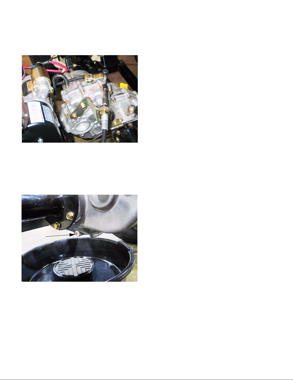
2.9. A blocked vent can provoke oil leaks. The vent is
located at the top of the transaxle housing.
See Figure 2.9.
Vent line
Figure 2.9
2.10. To change the gear lube: Clean the area
around the fill and drain plugs before removing
either.
2.13. Remove the oil fill cap/dipstick. This will allow air
to enter the transaxle faster, which will allow the
gear lube to drain faster.
2.14. Install the drain plug and tighten it to a torque of
132 in.-lb. (15 N-m).
2.15. Add 68 fluid ounces (2.0 L) API “GL-5” hypoid
gear lube, and install the oil fill cap/dipstick.
• SAE 90 weight above 41deg. f. (5 deg. C.)
• SAE 80 weight below 41 deg. f. (5 deg. C.)
2.16. Confirm the correct fluid level by by inserting
(but not threading-in) the fill cap/dipstick, and
withdrawing it to read the level.
2.11. Place a drain pan under the transaxle.
See Figure 2.11.
Drain plug
Figure 2.11
2.12. Remove the drain plug at the lower left corner of
the transaxle using a 12mm wrench.
NOTE: 80 and 90 weight gear lubes are very
thick at low temperatures, and may take considerable time to drain if the ambient temperature is
below 41 deg. f. (5 deg. C.)
2
K&T Saw Shop 606-678-9623 or 606-561-4983
Page 7
www.mymowerparts.com
Poly Bed 4 X 2 Drive System
3. DIAGNOSIS: CONFIRMING TRANSAXLE FAULT
3.1. Get as much information as possible from the
customer regarding symptoms and circumstances.
3.1. Inspect the vehicle for physical damage and
clues regarding the nature and cause of failure.
3.2. Carefully operate the vehicle if possible, to confirm noises and symptoms.
3.3. Confirm whether the problem is internal, in the
shift linkage, brake system, or the belt drive system (CVT):
• If a drive gear (forward or reverse) or the differential lock fail to engage or disengage by manually overriding the shift mechanism.
• Shift mechanism issues can be isolated from
internal issues by disconnecting the cables at
the transaxle end, and operating the transaxle
directly.
• Performance problems such as failure to reach
full speed are likely to be caused by engine,
brake, or belt/clutch issues.
• Complaints of “lurchy” operation are an indication that the brakes may be dragging or adjusted
too tight.
• It is easy to check for dragging brakes by pushing the vehicle with the parking brake released,
or by jacking-up the back of the vehicle and
checking the wheels for ease-of rotation.
• Refer to the “Brake” section of this manual for
service and adjustment information.
• Gear clash can result from drive being applied to
the input shaft during shifting. Refer to the
“CVT” section of this manual for performance
information.
• Gear “spit-out” or gear clash when the gear
selector is in Neutral can result from a misadjusted shift linkage. Refer to the “Transmission Linkage” section of this manual.
4. TRANSMISSION LINKAGES
Shift Control Cable
4.1. It is possible to remove the gear shift control
cable and gear shift control independently or
together.
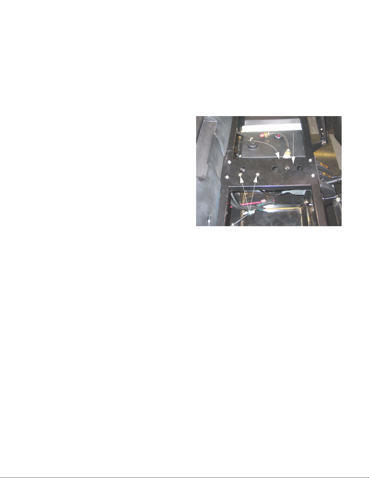
4.2. To gain access to the gear shift control, tilt both
seats forward, and remove the console/cup
holder using a 7/16” wrench. See Figure 4.2.
Differential
lock return spring
4.3. Unbolt the console support plate from the frame
using a 7/16” wrench.
NOTE: The vacuum driven fuel pump is
mounted to the bottom of the console support
plate. It may be unbolted from the plate using a
pair of 7/16” wrenches so that the plate may be
completely removed. It is not absolutely necessary to unbolt the fuel pump if the support plate
is only moved aside for access.
4.4. Un-hook the differential lock return spring from
the console support plate, and move (or remove)
the plate.
Console support plate
Fuel pump mounting bolts
Figure 4.2
• Under-steer (vehicle is less responsive to steering wheel in-puts) accompanied by rear wheel
squeal during turning maneuvers indicates that
the differential lock is engaged. If this condition
exists when the differential lock lever is
released, refer to the “Transmission Linkages”
section of this manual.
K&T Saw Shop 606-678-9623 or 606-561-4983
3
Page 8
Poly Bed 4 X 2 Drive System
www.mymowerparts.com
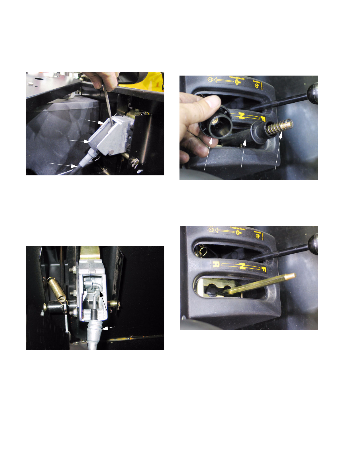
4.5. There is a black plastic cover on the gearshift
control. Slide it rearward, then lift it away from
the gear shift control to expose the cable attachment. See Figure 4.5.
Gear shift control
Plastic cover
Gear shift cable
Figure 4.5
NOTE: There is a lip at the front edge of the
cover that will provide sufficient purchase to
slide the cover back.
4.6. With the cover removed, lift the shift control
cable housing end out of the recess that locates
it in the shift control housing. See Figure 4.6.
Shift Control
4.8. If the shift control is to be removed, the knob
must be taken-off the shift lever. It threads off.
See Figure 4.8.
Knob Lock collar Spring
Figure 4.8
4.9. The knob retains a spring and a lock collar. Both
can be removed after the knob is taken off.
See Figure 4.9.
Hook
Cable housing end
Figure 4.6
4.7. Disengage the hooked end of the cable from the
shift control and lift the cable out of the shift control housing.
K&T Saw Shop 606-678-9623 or 606-561-4983
Figure 4.9
4.10. Three nuts and bolts secure the shifter control to
the frame. The nuts may be removed with a pair
of 7/16” wrenches. The shifter control may then
be removed.
4.11. There are no internal replacement parts available through Cub Cadet for the shifter control. It
is to be replaced as an assembly.
4
Page 9
www.mymowerparts.com
Poly Bed 4 X 2 Drive System
4.12. Within the housing for the shifter control there is
a torsion spring that returns the shift lever to the
center of its travel. There is not a detent mechanism in the shifter control. See Figure 4.12.
Return spring
Figure 4.12
4.13. On installation of the shifter control:
4.16. Match-mark the shifter arm to the splined end of
the shift arm shaft, then remove the clamp bolt
using a 10 mm wrench.
NOTE: The clamp bolt engages a groove in the
shift shaft. It must be removed.
4.17. Use a pair of 7/8” wrenches to remove the end
jam nut on the threaded end of the cable housing. The cable core will pass through a slot in
the bracket. See Figure 4.17.
Jam nuts
• Position the bolts in the shifter control housing
prior to installation. There is insufficient lateral
clearance to instal them all in-situ.
• Tighten the nut to 96 in-lb. (10.848 Nm). If the
nuts are too tight, the housing will distort, and
operating effort will increase.
4.14. If the cable is to be replaced, the front end of the
cable can be disconnected as described in the
procedure for removal of the shifter control.
4.15. The back end of the cable is permanently
attached to the shifter arm. See Figure 4.15.
Index
mark
Clamp bolt
Figure 4.17
4.18. The cable can be withdrawn from the vehicle in
either direction. See Figure 4.18.
Note cable routing
Figure 4.18
NOTE: The correct routing of the cable: through
the recess in the lower front corner of the tank.
4.19. Confirm that the cable is correctly adjusted
Figure 4.15
5
before returning the vehicle to service.
K&T Saw Shop 606-678-9623 or 606-561-4983
Page 10
Poly Bed 4 X 2 Drive System
www.mymowerparts.com
Shift Control Adjustment
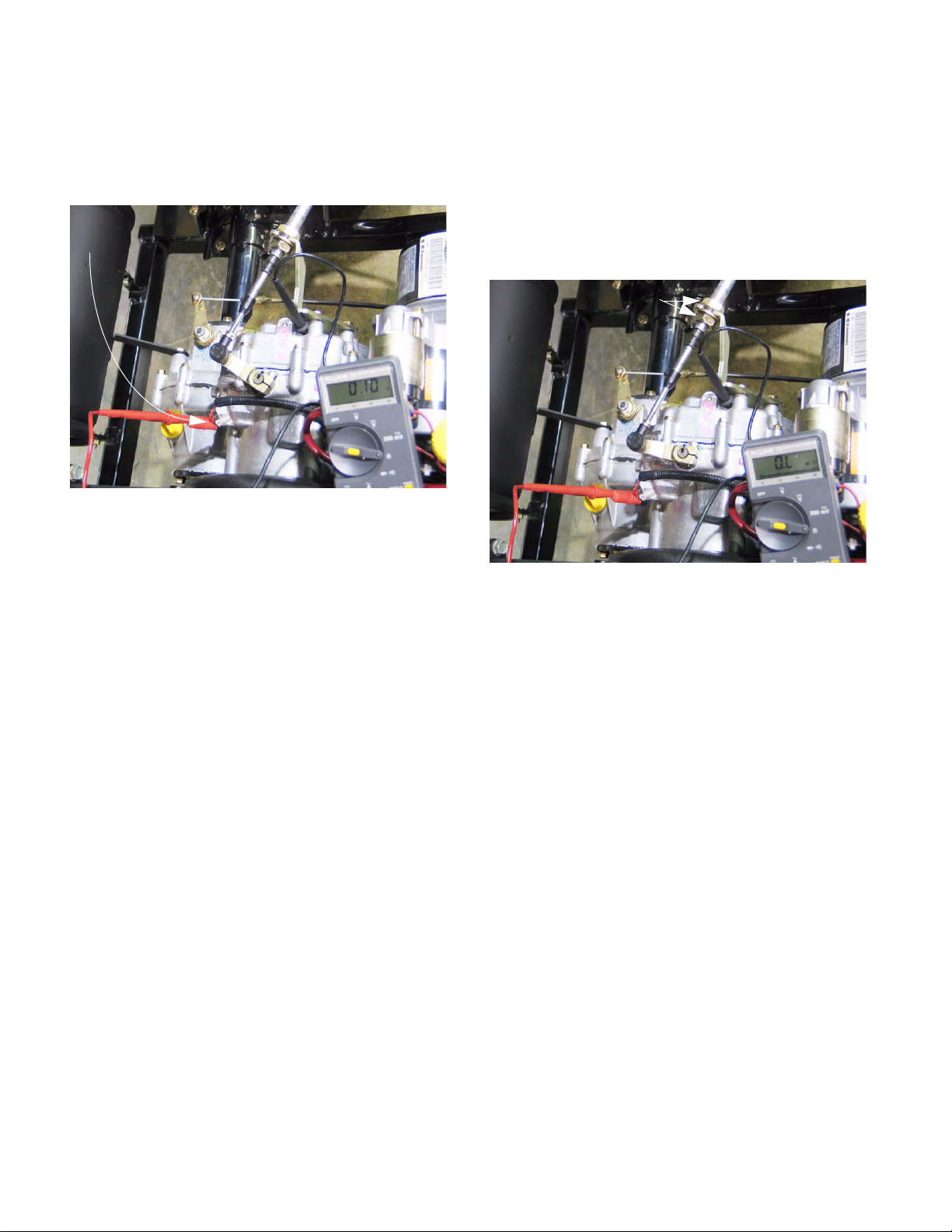
4.20. To adjust the shift cable, use the neutral safety
switch to confirm the neutral position.
See Figure 4.20.
Use safety switch
to find neutral
Figure 4.20
• Connect a powered continuity light or an Ohm
meter between the terminal on the neutral switch
and a good ground. This test works key-off.
4.21. With the transmission confirmed to be in neutral
by the meter or light connected to the switch,
move the gearshift lever to the neutral position.
4.22. Adjust the jam nuts as necessary so that the
contacts in the neutral switch open when the
gearshift lever is moved an equal distance in the
direction of forward and reverse gear positions.
See Figure 4.22.
Adjust cable here
Figure 4.22
• Otherwise, connect a test light in series between
the terminal on the neutral switch and the eyelet
on the wire that attaches to it. This test works
key-on, engine-off.
• When the continuity or test light bulb illuminates,
or the Ohm meter registers zero, the contacts
within the switch are closed.
• When the neutral switch is closed, the transmission is in neutral. Move the shifter through its
range of travel to confirm that the switch is working correctly.
• There is a significant range of travel around the
neutral position before the contacts in the neutral
switch open.
4.23. Tighten the jam nuts and test the operation of
the shift control before returning the unit to service.
4.24. Inspect the cable for wear or damage. Replace
it if there are any signs of fraying, binding, kinking or damage to the cable housing.
4.25. Lubricate the cable with light oil (penetrating oil
or cable lube) any time it is removed, and at 500
hr. intervals when the gear lube is changed.
4.26. Depending on the type of service being done,
the gear shift control cable may be removed
from it sprocket on the transaxle, or the bracket
may be removed from the transaxle housing
using a 10 mm wrench.
4.27. On installation, the gear shift control bracket
should be tightened to a torque of 78 in-lb. (8.8
N-m).
6
K&T Saw Shop 606-678-9623 or 606-561-4983
Page 11
www.mymowerparts.com
Poly Bed 4 X 2 Drive System
Differential Lock Control
In normal operation, a differential allows the two rear
wheels to rotate at different speeds. In a turning
maneuver, the wheels toward the outside of the turn
follow a path that describes a greater circumference
than the wheels toward the inside of the turn. Because
the outside wheels must turn faster than the inside
wheels, a differential is necessary.
Because it allows the rear wheels to rotate at different
speeds, a standard differential can only provide drive to
one wheel. One method of getting more traction is to
provide a manual device that over-rides the differential
feature by locking the two sides of the differential
together, providing drive to both rear wheels at the
same time.
It is not desirable to lock the differential together all the
time because it limits the turning radius of the vehicle:
• The two wheels driving at the same speed tend
to want to push the vehicle straight ahead.
• When the vehicle does turn, the two rear wheels
will fight against each-other for traction. In the
process they will apply exaggerated loads to the
drive train.
4.29. If the Big Country vehicle exhibits symptoms
indicating that the differential lock is not engaging or disengaging properly, investigation should
begin with the control cable.
4.30. The differential lock control lever pivots on a
large clevis pin. The clevis pin is secured to the
frame by a hairpin clip.
4.31. The spring on the end of the differential lock control cable connects to one arm of the differential
lock control lever, and a return spring connects
to the other arm. The other end of the return
spring hooks to the console support bracket.
4.32. To reach the differential lock control and cable:
See Figure 4.32.
Return spring, disconnected from
console support bracket
4.28. In normal use:
• The differential lock should engage when the differential lock lever is pulled-up.
• There are five engagement dogs on the differential. The rear wheels must rotate at most 72
degrees relative to one-another before the
engagement dogs align, allowing them to lock
together.
• Pulling-up on the differential lock lever extends
the spring at the front of the differential lock control cable. The spring applies force to the cable
and the differential lock lever on the transaxle.
When the engagement dogs align, the spring
force will push them into engagement.
• Once engaged, the lever may be released, and
the differential will remain locked until the drive
load on the left and right wheels is equalized.
• When the drive load between the rear wheels is
equalized, the load on the differential lock dogs
is relieved. When the load is relieved, torsion
spring on the differential lock lever will overcome the friction between the differential lock
dogs, and cause them to disengage.
Control cable
Figure 4.32
• Fold the seats forward.
• Remove the tool box from beneath the passenger seat, if so equipped.
• Remove the cup holder/console using a 7/16”
wrench.
• Unbolt the console support bracket using a 3/8”
wrench.
• Unhook the differential lock control return spring,
and move the console support bracket aside.
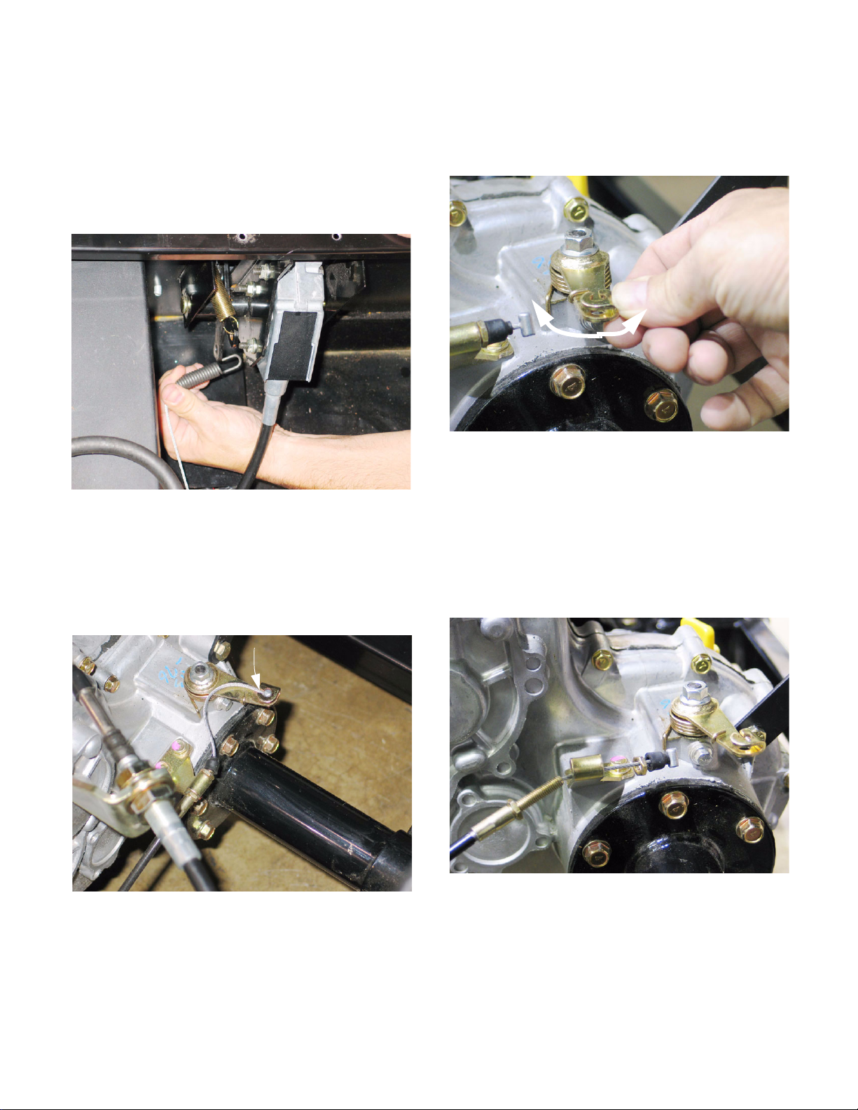
4.33. Operate the differential lock control lever, and
observe the movement of the cable and differential lock lever on the transaxle.
NOTE: It may be necessary to rotate one of the
rear wheels to align the differential lock dogs
before full engagement will occur. This is normal.
7
K&T Saw Shop 606-678-9623 or 606-561-4983
Page 12
Poly Bed 4 X 2 Drive System
www.mymowerparts.com
4.34. If the linkage binds, disconnect the cable to isolate the external portion of the linkage from internal transaxle components.
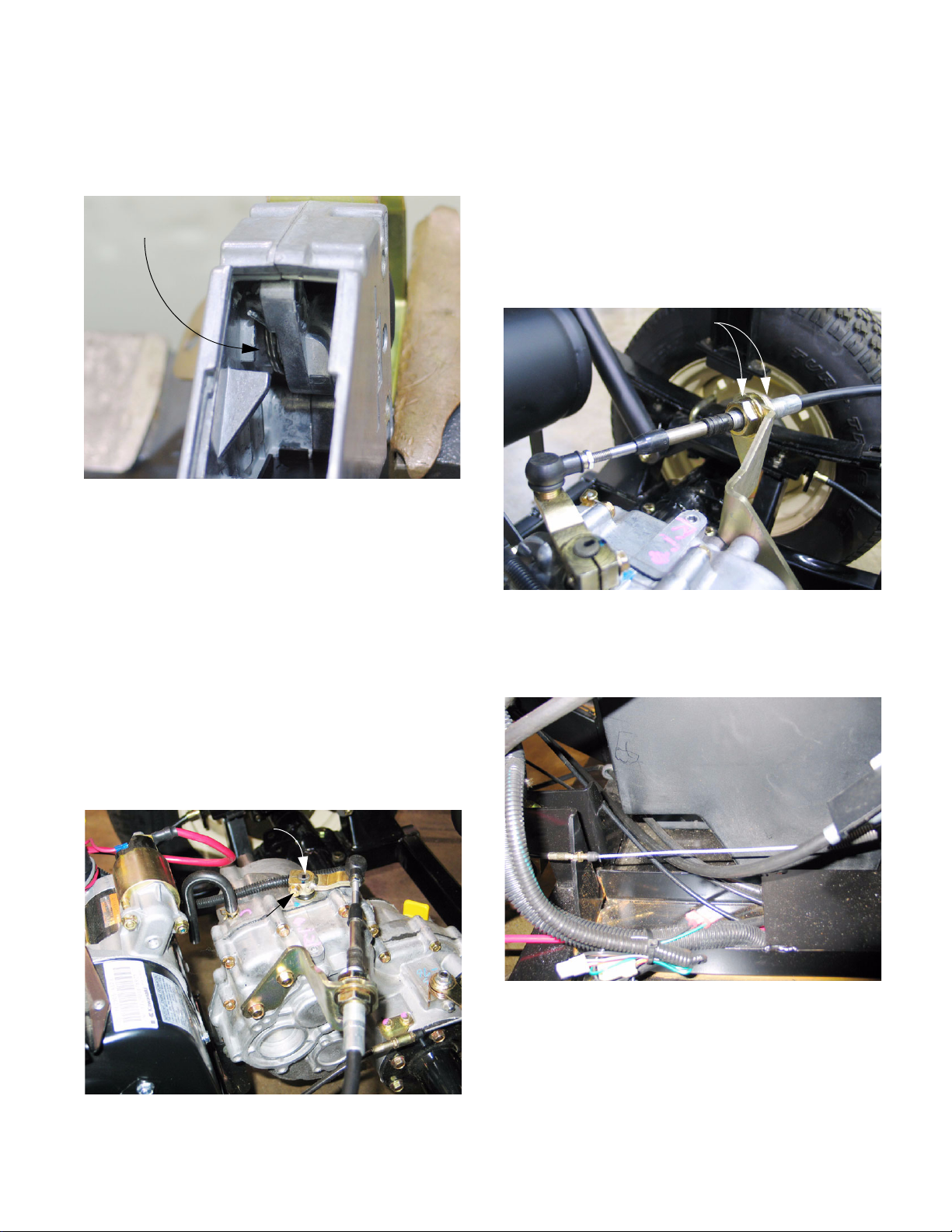
4.35. Disconnect the differential lock control cable
from the differential lock control lever: Pull the
cable forward to get clearance to unhook the
spring at the end of the cable. See Figure 4.35.
Figure 4.35
4.36. There is sufficient slack in the cable to disconnect the barrel on the rear end of the cable from
the differential lock lever on the transaxle as
well: either end may be disconnected first.
See Figure 4.36.
4.37. With the cable disconnected, check the operation of the differential lock lever, and the torsion
spring that returns it to the unlocked position.
See Figure 4.37.
Figure 4.37
NOTE: Confirm that the torsion spring is prop-
erly positioned. Replacement of the torsion
spring with one that has a shorter leg was the
subject of Service Bulletin CC-456
4.38. The back of the cable is secured to the cable
holder by a pair of jam nuts: one on each side of
the cable holder. See Figure 4.38.
Disconnect barrel
from arm
Figure 4.36
Figure 4.38
4.39. Depending on the nature of the repair, the cable
holder can be unbolted from the transaxle housing, or the rear jam nut can be removed and the
cable withdrawn from the holder. A 10mm
wrench will fit the jam nuts and the cable holder
bolts.
8
K&T Saw Shop 606-678-9623 or 606-561-4983
Page 13
www.mymowerparts.com
Poly Bed 4 X 2 Drive System
4.40. Tighten the cable bracket mounting bolts to a
torque of 78 in-lb. (8.8 N-m) on installation.
4.41. The cable is secured to a bracket near the front
mounting point of the engine and transaxle cradle. See Figure 4.41.
Note: cable routing
Figure 4.41
4.42. The cable is secured by two jam nuts that can be
removed using a 10 mm wrench.
4.46. The clevis pin that holds the differential lock control lever to the frame cannot be removed with
the fuel tank secured in position.
See Figure 4.46.
Move fuel tank
to remove pin
Figure 4.46
4.47. The fuel tank bracket assembly can be removed
using 7/16” wrench. See Figure 4.47.
4.43. Correct cable routing: cable mounted to right
side of bracket, then curved to the left to pass
beneath the air filter bracket.
4.44. Inspect the cable for wear or damage. Replace
it if there are any signs of fraying, binding, kinking or damage to the cable housing.
4.45. Lubricate the cable with light oil (penetrating oil
or cable lube) any time it is removed, and at 500
hr. intervals when the gear lube is changed.
Figure 4.47
9
K&T Saw Shop 606-678-9623 or 606-561-4983
Page 14
Poly Bed 4 X 2 Drive System
www.mymowerparts.com
4.48. With the bracket removed, the fuel tank can be
moved far enough back to allow the clevis pin to
be removed. See Figure 4.48.
Pin removal
Figure 4.48
4.49. Apply anti-seize compound or white lithium
grease to the portion of the pin that the differential lock control lever pivots on when it is reinstalled.
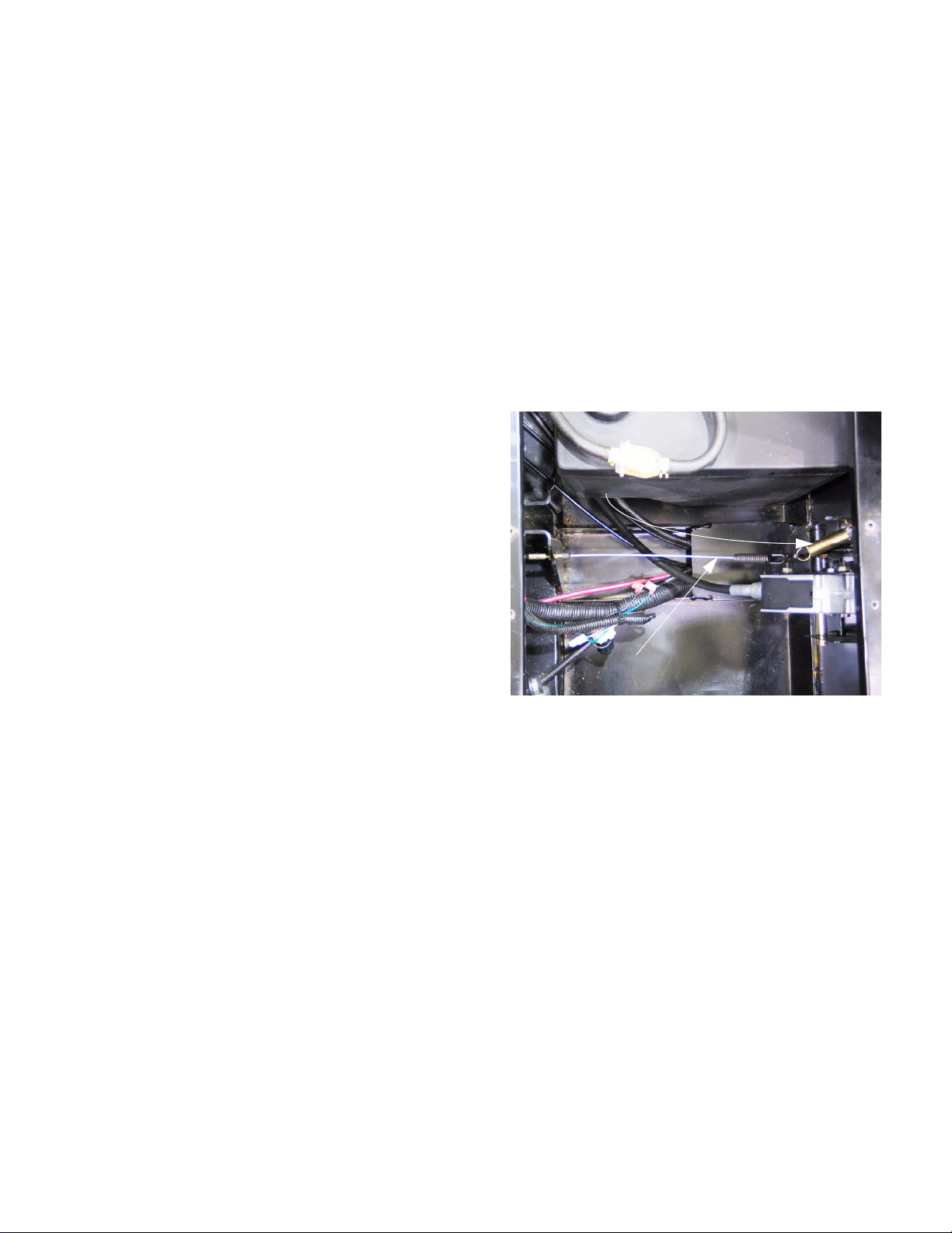
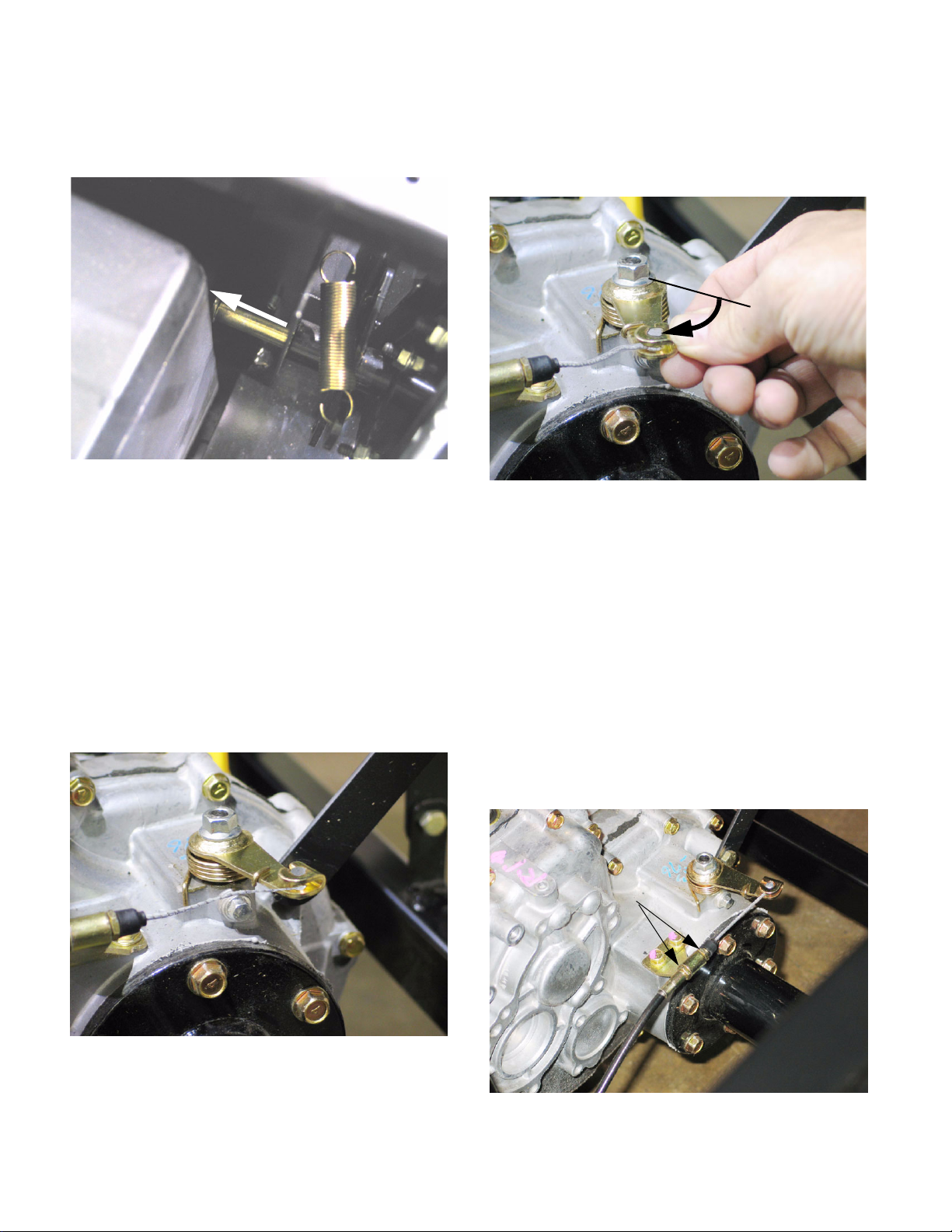
Differential Lock Control Cable Adjustment
4.50. When the differential lock is disengaged, the
spring at the front of the cable should be fully
retracted, there should be slight slack in the
cable, and the differential lock control arm
should be at the end of its rearward travel (all the
way back). See Figure 4.50.
4.51. When fully engaged, the differential lock arm
should pull forward about 7/8” (2.22 cm) as measured at the center of the barrel on the end of the
cable core. See Figure 4.51.
7/8”
Figure 4.51
4.52. There is much more travel available to the cable
than is necessary to fully engage the differential
lock. The spring at the front of the cable accommodates the over-travel.
4.53. As long as the arm on the transaxle hits the back
end of its travel when the differential lock is
released, and hits the front end of its travel when
the differential lock is engaged, the cable adjustment is correct.
4.54. If cable adjustment is necessary, it may be
accomplished with the jam nuts on either side of
the differential lock cable bracket.
See Figure 4.54.
Easiest point for
cable adjustment
Figure 4.50
Figure 4.54
10
K&T Saw Shop 606-678-9623 or 606-561-4983
Page 15

www.mymowerparts.com
Poly Bed 4 X 2 Drive System
5. DIAGNOSIS AND SERVICE: DRIVE BELT AND CLUTCHES (CVT OR CONTINUOUSLY VARIABLE TRANSMISSION)
5.1. Performance problems such as lack of power or
failure to reach full speed may be caused by:
engine performance issues, dragging brakes, or
belt/clutch issues.
5.2. Confirm whether the problem is internal to the
transaxle, in the brake system, or in the belt
drive and pulley system (CVT):
Transaxle
• If one drive gear (forward or reverse) or the differential lock fail to engage or disengage by
manually overriding the shift mechanism.
• Problems originating in the CVT will effect travel
in both forward and reverse: The belt and
clutches act on the input shaft of the transaxle.
• If forward or reverse gear is engaged, the
brakes released, and the vehicle is pushed, the
input shaft of the transaxle should rotate.
• The driven pulley is visible through an air
exhaust port in the back of the belt cover. It
should rotate with the input shaft of the transaxle.
• If the driven pulley does not rotate when the
vehicle is pushed in gear, the problem lies within
the transmission, the gear shift control/cable, or
the driven pulley has come loose from the input
shaft.
Brakes
• Complaints of “lurchy” operation are an indication that the brakes may be dragging or adjusted
too tight.
• It is easy to check for dragging brakes by pushing the vehicle with the parking brake released,
or by jacking-up the back of the vehicle and
checking the wheels for ease-of rotation.
• Refer to the “Brake” section of this manual for
service and adjustment information.
Engine
• Engine performance issues will likely be accompanied by other engine-based symptoms: oil
smoke, black smoke from an overly rich condition, rough running, or poor idle quality.
CVT
• Gear clash can result from drive being applied to
the input shaft during shifting (at idle speed).
• Possible causes of drive force being applied at
idle speed include: high idle speed, misalignment between engine and transaxle, wrong belt,
damaged driving pulley or damaged driven pulley.
• Loss of drive (complete or slippage) may occur
because of a worn belt, wet belt / pulleys, damaged pulleys.
• Loss of top speed other than engine or brake
problems) may occur because of a worn belt,
wet belt / pulleys, damaged pulleys.
• Most CVT diagnosis is done through simple
observation and measurement.
• This is an enclosed drive system with an air filter
and a cooling fan. Loss of air-flow will cause the
CVT to over-heat, and will effect performance.
Maintenance
• The CVT system should be inspected at 250
hour or 1 year intervals. The air filter should be
removed and inspected, and the CVT cover
should be removed for belt measurement and
inspection.
• The air filter should be inspected every 50 hours
of operation.
• Air filter life will vary with operating conditions. A
dusty environment will necessitate more frequent maintenance of the engine and CVT air filters.
• Belt life will vary with operating conditions. High
load, high ambient temperatures, dusty conditions, operation on grades, and high number of
stop/start cycles are among factors that will tend
to shorten belt life.
• Any change in performance noted by the operator should prompt inspection.
• Any factors indicative of potential drive problems
should prompt inspection. eg.: evidence of
rodent nesting, or evidence of oil leakage from
engine or transaxle.
• Refer to the Engine” section of this manual for
diagnosis and repair of engine performance
issues.
K&T Saw Shop 606-678-9623 or 606-561-4983
11
Page 16
Poly Bed 4 X 2 Drive System
www.mymowerparts.com
Inspection
5.3. Park the vehicle on a firm level surface, with the
ignition turned off, and lift the load bed to provide
access to the drive system.
5.4. Allow the exhaust system to cool before proceeding.
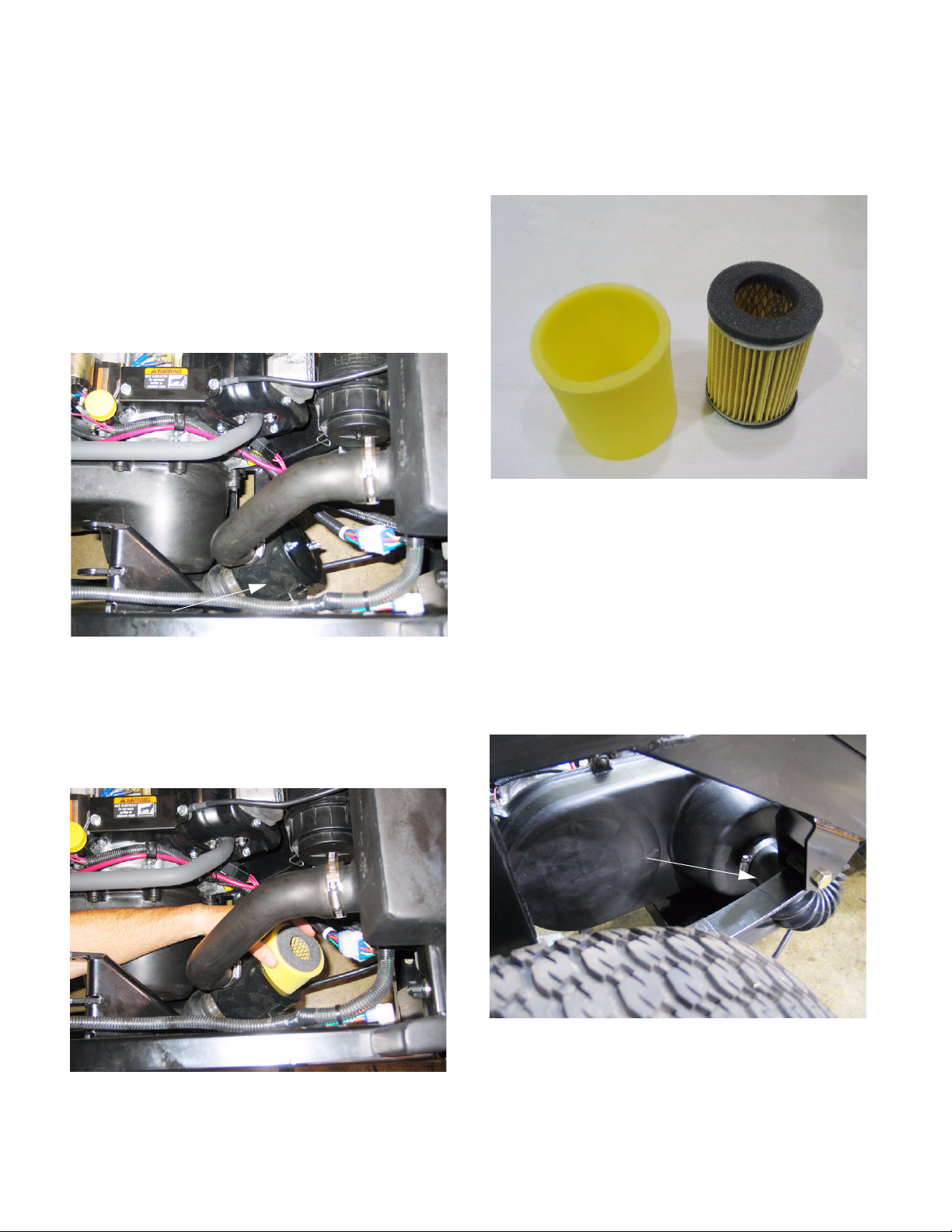
5.5. Inspect the CVT system air filter. The filter is
located in front of the outer cover for the CVT. It
is connected to the intake plenum by a molded
hose, and it is connected to the outer CVT cover
by a flexible hose. See Figure 5.5.
5.8. The CVT air filter has a foam wrap pre-filter over
the paper filter element. The foam wrap can be
washed in mild detergent, rinsed, dried, and reused. Do not oil the foam wrap. See Figure 5.8.
CVT pre-filter CVT air filter
Figure 5.8
5.9. The paper filter can be tapped-out. Do not blow
it clean with pressurized air. Replace it if it
shows significant dirt between the pleats.
CVT filter housing
Figure 5.5
5.6. Remove the two wing screws from the air filter
cover.
5.7. Lift the cover and remove the filter.
See Figure 5.7.
5.10. To remove the CVT drive cover, the air filter
assembly must be removed.
5.11. Loosen the hose clamp that secures the flexible
hose from the air filter to the CVT cover, and disconnect the hose from the cover.
See Figure 5.11.
Flexible hose from plenum
via filter, to CVT
Figure 5.11
Figure 5.7
12
K&T Saw Shop 606-678-9623 or 606-561-4983
Page 17
www.mymowerparts.com
Poly Bed 4 X 2 Drive System
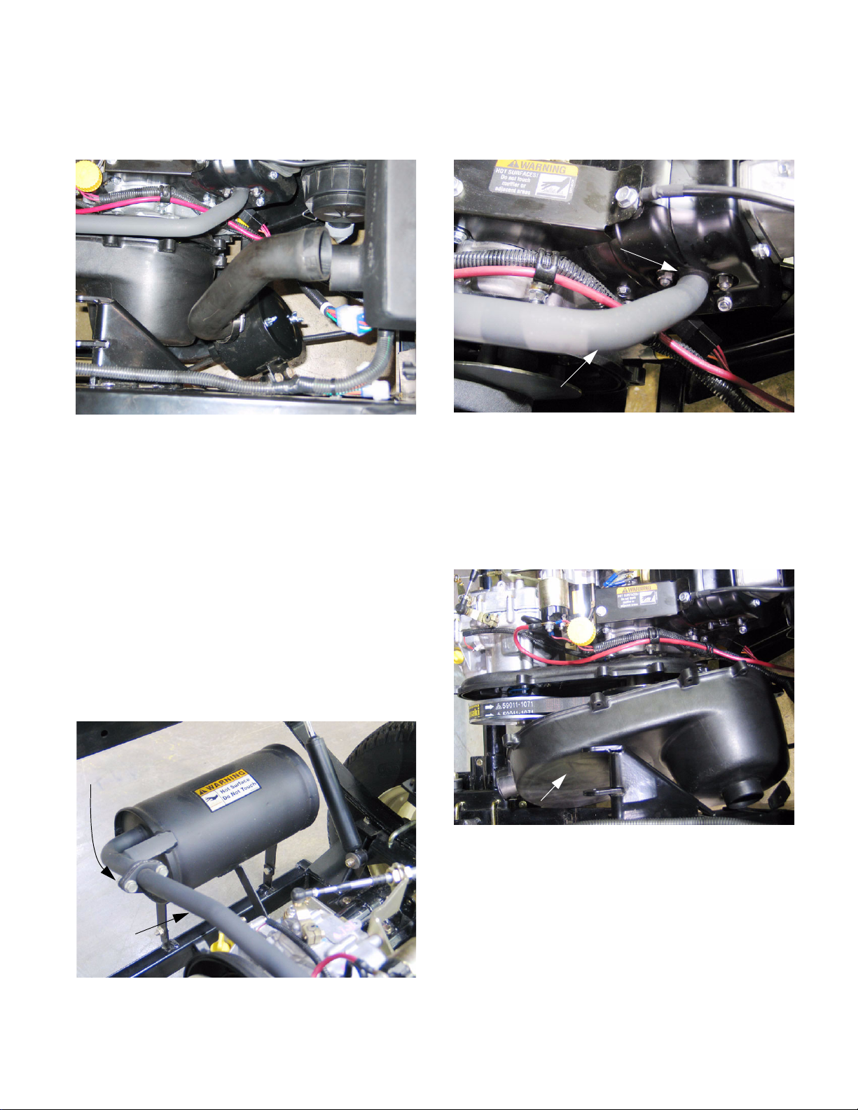
5.12. Loosen the hose clamp that secures the molded
hose from the air filter to the plenum.
See Figure 5.12.
Figure 5.12
5.13. Remove the two bolts that hold the air filter
housing to the air filter bracket using a 1/2”
wrench, and remove the filter assembly.
5.14. The exhaust pipe interferes with the removal of
the CVT cover. It must be removed.
5.16. Disconnect the front flange of the exhaust pipe
from the cylinder head using a 12 mm wrench.
See Figure 5.16.
Flange mount to cylinder head
Exhaust pipe
Figure 5.16
5.17. Remove the exhaust pipe.
5.18. Remove the 9 screws holding the CVT cover to
the CVT housing using an 8 mm wrench, and
maneuver the cover out of the engine compartment. See Figure 5.18.
NOTE: For testing and diagnostic purposes,
existing exhaust flange gaskets may be re-used.
Any time the exhaust pipe is removed, it should
be reinstalled using new gaskets before returning the vehicle to service.
5.15. Disconnect the rear flange of the exhaust pipe
from the muffler using two 13 mm wrenches.
See Figure 5.15.
Flange mount to
muffler
Exhaust
pipe
CVT cover removed
Figure 5.18
Figure 5.15
13
K&T Saw Shop 606-678-9623 or 606-561-4983
Page 18

Poly Bed 4 X 2 Drive System
www.mymowerparts.com
5.19. Inspect the belt and clutches (pulleys) for obvious damage and wear: See Figure 5.19.
21 mm min.
Figure 5.19
• The belt should measure at least.827” (21 mm)
across the outside (wide) surface (service limit).
If it measures less than this it is worn, and
should be replaced.
• New belts should measure .906” (23 mm).
• Confirm that the correct belt is on the vehicle:
Cub Cadet Part # 754-04054.
• The arrow printed on the belt should point in the
direction of the belts rotation.
5.20. With the transaxle in neutral, it should be possible to rotate the driven pulley (on the transaxle)
without applying a force of more than 20 in-lbs.
(2.26 Nm) to the driving pulley (on the engine).
See Figure 5.20.
• A torque wrench with a 13 mm socket on it
should read less than 20 in.-lbs.(2.26 Nm) while
rotating the input shaft. The belt should slip easily on the driving pulley.
• If this figure is exceeded, remove the belt and
repeat the test. This will confirm if the bind is
internal or external.
• If the problem is internal, examine the transaxle,
if the problem is external, examine the CVT.
• If there is excessive drag, and the outer sheave
of the driving pulley is fully retracted, there may
be an alignment or spacing problem between the
crankshaft of the engine and the input shaft of
the transaxle. If there is an alignment problem,
it may be indicated by asymmetric wear on the
belt.
5.21. The distance between the centerline of the
crankshaft and the centerline of the input shaft
should be 9.41” (23.9 cm). The two shafts must
be parallel in vertical and horizontal axis.
NOTE: As a practical matter, this is a difficult
measurement to make without specialized fixtures. A combination of measurement, adjustment, and experimentation may be necessary in
the field.
5.22. To check the performance of the CVT, install the
exhaust pipe, but leave the CVT exposed for
observation.
5.23. Connect a tachometer to the engine.
5.24. With the vehicle in neutral, insure that no unsafe
conditions will arise from starting the engine.
NOTE: Perform the following procedure with all
due caution to ensure that no foreign objects,
including the technician, come into contact with
rotating components.
20 in-lbs to rotate here
Figure 5.20
K&T Saw Shop 606-678-9623 or 606-561-4983
14
Page 19
www.mymowerparts.com
Poly Bed 4 X 2 Drive System
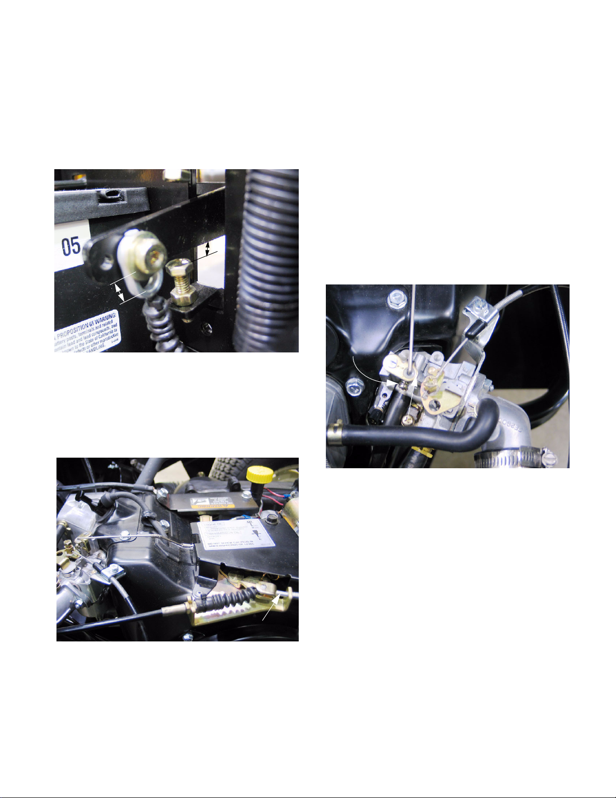
5.25. Confirm that the throttle cable, and the travel
stops on the throttle cable are adjusted to provide the full range of travel without straining the
cable:
5.26. There should be roughly 3/16” (4.8 mm) of play
at the eyelet that connects the throttle cable to
the throttle pedal. See Figure 5.26.
3/16” free play
3/16” free play
Figure 5.26
• The adjustment can be made through a combination of stop bolt (1/2” wrench) and throttle
cable position (two 10 mm wrenches).
• Too little pedal travel in comparison to available
cable travel will result in sub-optimal engine performance.
• Too much pedal travel, in comparison to available cable travel will “load” the linkage, and may
damage components through bending or fatigue.
• Tension on the cable when the pedal is at rest,
or a cable that fails to return all the way to idle
position may cause an artificially high idle speed.
5.28. Start the engine and check the idle speed controlled by the stop-screw on the throttle arm of
the carburetor. See Figure 5.28.
Stop screw Set throttle stop
idle to 1100 RPM
5.27. The throttle pedal arm should reach the end of
its available travel, as set by the stop-bolt and
jam nut as the governor linkage reaches the end
of its travel at the engine end of the cable.
See Figure 5.27.
Governed idle stop
Figure 5.27
Throttle arm
Figure 5.28
NOTE: The engine should be fully warmed-up
prior to this adjustment. Engine temperature has
a significant effect on idle speed.
15
K&T Saw Shop 606-678-9623 or 606-561-4983
Page 20
www.mymowerparts.com
Poly Bed 4 X 2 Drive System
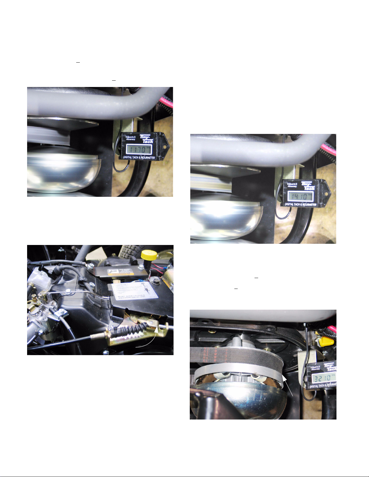
5.29. Hold the throttle arm against the stop screw.
Adjust the stop screw to set the engine speed to
1,100 RPM +
5.30. Release the throttle arm, then set the governed
idle speed to 1,200 RPM +
50.
50. See Figure 5.30.
Figure 5.30
NOTE: If the idle speed is set too low, the engine
will stall at idle. If warm idle speed has fallen
with time, check the condition of engine tune-up
factors (compression, valve lash, spark plug, air
filter) before making adjustment.
5.32. Gradually increase the speed of the engine
(manually, not through adjustment), and observe
the point where the outer sheave of the driving
pulley moves in to compress against the belt.
See Figure 5.32.
Driving clutch
at start of
travel
5.31. The idle speed is controlled by the phillips head
screw on the governor control panel.
See Figure 5.31.
Set governed idle here
Figure 5.31
NOTE: If the idle speed is set too high, the driv-
ing pulley will begin to apply force to the belt.
This will turn the input pulley of the transaxle
with enough force to cause gear clash when forward or reverse gear are engaged, and it may
cause difficulty in disengaging drive gears.
Figure 5.32
5.33. The belt should be squeezed between the
sheaves at 1,400 +
5.34. By 3,300 +
driving pulley should be fully extended.
See Figure 5.34.
100 RPM the outer sheave of the
100 RPM.
Driving clutch
fully engaged
Figure 5.34
16
K&T Saw Shop 606-678-9623 or 606-561-4983
Page 21
www.mymowerparts.com
Poly Bed 4 X 2 Drive System
5.35. As the driving pulley compresses the belt, it is
forced outward in the tapered sheave.
NOTE: As the effective diameter of the driving
pulley increases, the belt is drawn deeper into
the sheave of the spring loaded driven pulley,
reducing its effective diameter. The combined
effect changes the drive ratio as speed goes up.
NOTE: Because the outer sheave of the driving
pulley is fully extended by around 3,300 RPM,
any vehicle speed increase beyond 3,300 RPM
engine speed is due directly to increases in
engine RPM, not to shifts in the effective drive
ratio.
5.36. If the vehicle fails to reach full speed (20 MPH)
or has lost performance, and the belt is good,
confirm that the engine still achieves it’s specified top-no-load speed and that the CVT
responds accordingly.
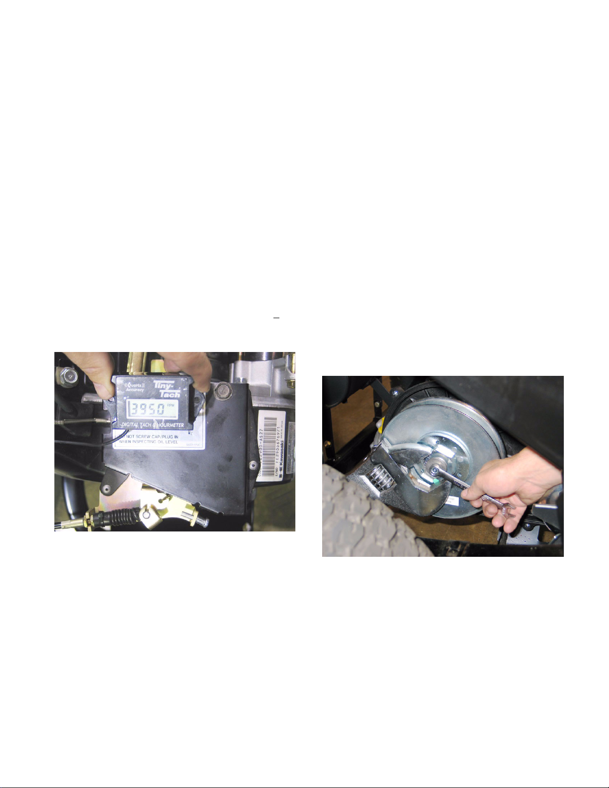
5.37. Top-no-load engine speed should be 4,000 +
RPM. Confirm this with a tachometer.
See Figure 5.37.
50
CVT Removal: Belt and Pulleys
5.39. Remove the exhaust pipe and CVT cover as
described previously in this section.
NOTE: If the belt is to be removed, but the pulleys are to be left in-place, it is not necessary to
remove the exhaust pipe. The CVT cover can
be moved aside, and the belt slipped-out. The
CVT cover does not need to be completely
removed to change a belt.
5.40. Disconnect and ground the spark plug H.T. lead.
5.41. If the pulleys are to be removed, loosen the bolts
that hold the pulleys to their respective shafts
before removing the belt.
NOTE: The bolts securing both CVT pulleys are
left hand thread. Turn them clockwise to
loosen them.
5.42. The driven pulley on the input shaft of the transaxle can be removed using a 12 mm wrench.
Use an adjustable face pin spanner with reach of
at least 3” (7.62 cm) and a 1/4” (6 cm) pin size
(Snap-On stock number AFS483 is suitable) to
keep the pulley from rotating. See Figure 5.42.
Figure 5.37
NOTE: The governor cover is riveted to the con-
trol plate. It is not adjustable.
5.38. If the engine fails to reach the specified top noload speed, or lacks performance under a light
load, check engine performance factors as
described in the Engine section of this manual:
• Ignition function and spark plug condition.
• Fuel system condition (fuel pump and lines, fuel
filter, air filter, carburetor, linkages).
• Engine mechanical condition (valve lash adjustment, cylinder compression, cylinder leakdown).
K&T Saw Shop 606-678-9623 or 606-561-4983
Figure 5.42
• Setting the parking brake will also help.
• If no other means are available, the pulley can
be held with a 2” (50 mm) wrench on the large
nut.
5.43. The bolt holding the driving pulley to the engine
crankshaft can be loosened using a 14 mm
wrench.
17
Page 22
Poly Bed 4 X 2 Drive System
www.mymowerparts.com
5.44. If it is necessary to hold the crankshaft from turning: choose one of three methods.
See Figure 5.44.
• Remove the spark plug using a 13/16” (21 mm)
wrench. With the piston rising on the compression stroke pack the cylinder with starter rope to
act as a piston stop.
• Remove the flywheel cover using 10 mm
wrench, and hold the flywheel nut using a 22 mm
wrench.
• Use a strap wrench on the driving pulley.
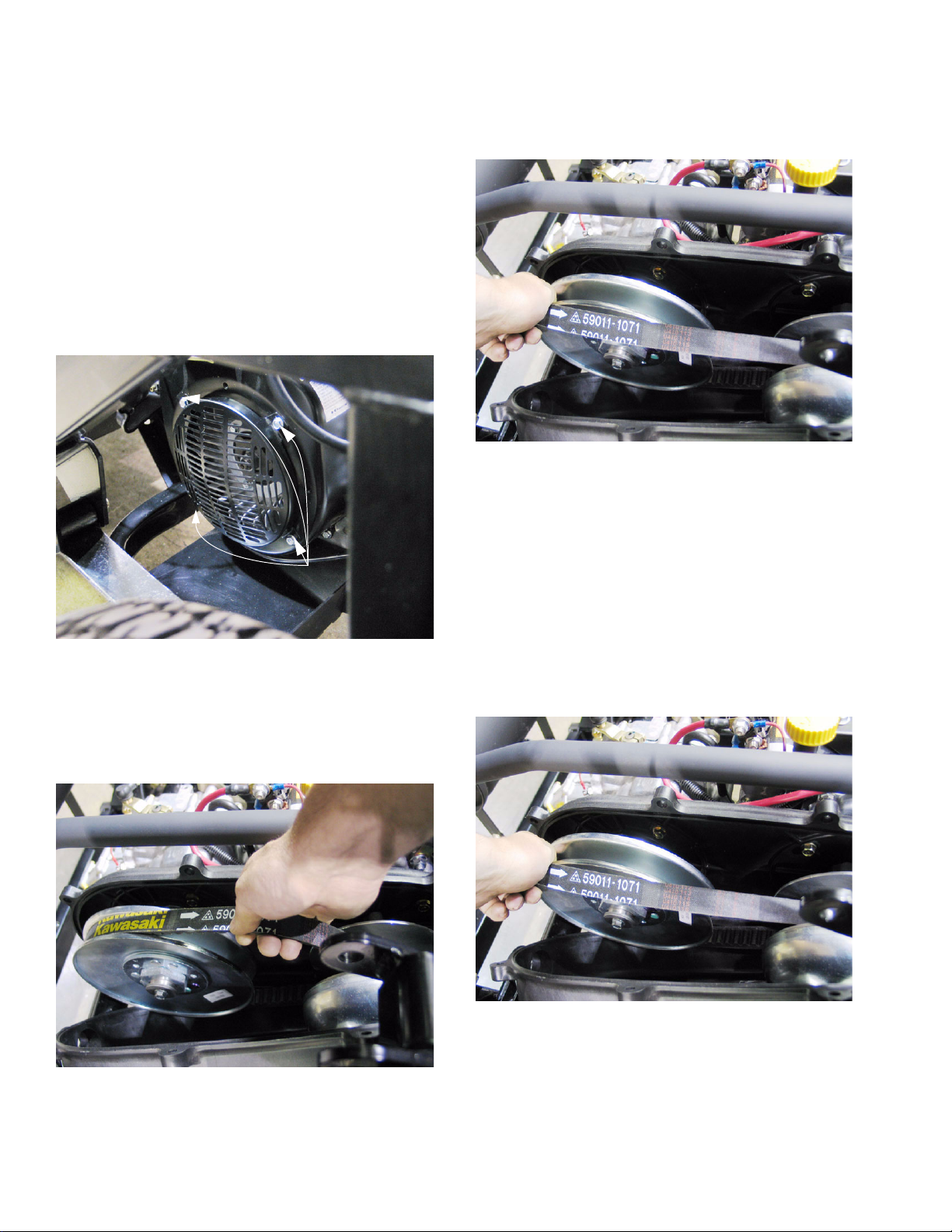
5.46. Roll the belt off of the driven pulley on the transaxle. See Figure 5.46.
Figure 5.46
5.47. To remove the driven pulley, begin by removing
the bolt that holds it to the input shaft of the transaxle using a 3/4” wrench.
Remove screws to reach
flywheel nut
Figure 5.44
5.45. Tug upward on the top run of the belt. This will
spread the sheaves of the driven pulley, and create enough slack in the belt to allow easy
removal. See Figure 5.45.
NOTE: If an impact wrench is not available, it
may be necessary to manually place the transmission in Forward gear and set the parking
brake.
5.48. Carefully roll the drive belt off of the driven pulley, then remove it from the driving pulley.
See Figure 5.48.
Figure 5.48
5.49. Reverse the process for installation.
Figure 5.45
18
NOTE: The arrow on the belt points in the direc-
tion of travel.
K&T Saw Shop 606-678-9623 or 606-561-4983
Page 23

www.mymowerparts.com
Poly Bed 4 X 2 Drive System
5.50. After the belt is removed, the driven pulley can
be removed: See Figure 5.50.
• Take the bolt and washer that secure the pulley
onto the transaxle input shaft completely off
using a 12 mm wrench.
• Slide the pulley off of the input shaft. It may be
necessary to carefully pry on the pulley hub.
• There is a key between the pulley and the input
shaft, and a spacer between the pulley and the
shoulder on the input shaft.
Spacer
Key
Driven pulley
5.54. After the belt is removed, the driving pulley can
be removed: See Figure 5.54.
• Remove the bolt and washer securing the driving pulley to the engine crankshaft using a 14
mm wrench.
• Slide the driving pulley off of the crankshaft.
• There is a key between the pulley and the input
shaft, and a spacer between the pulley and the
shoulder on the crankshaft. The spacer is
notched to fit over the key.
Figure 5.50
5.51. If the driven pulley does not function properly,
replace it as a complete unit.
5.52. On installation:
• Apply a small amount of anti-seize compound to
the input shaft.
• Confirm that the spacer and key are properly
positioned. The chamfered side of the spacer
should face the shoulder on the crankshaft.
• Slip the driven pulley all the way onto the input
shaft, and seat it against the spacer.
• Apply a small amount of thread locking compound such as Loctite 242 (blue) to the threads
of the bolt.
• Secure the pulley to the input shaft with the bolt
and washer. Tighten the bolt to a torque of: 24 ftlb (32 N-m).
5.53. Key points to inspect on the driven pulley are the
ramp surfaces on the cams, and the polymer
buttons that ride against the ramps.
Figure 5.54
5.55. If the driven pulley does not function properly,
replace it as a complete unit.
5.56. On installation:
• Apply a small amount of anti-seize compound to
the crankshaft.
• Confirm that the spacer and key are properly
positioned. The chamfered side of the spacer
should face the shoulder on the crankshaft. The
key should fit through the notch in the spacer.
• Slip the driven pulley all the way onto the input
shaft, and seat it against the spacer.
• Apply a small amount of thread locking compound such as Loctite 242 (blue) to the threads
of the bolt.
• Secure the pulley to the input shaft with the bolt
and washer. Tighten the bolt to a torque of: 31 ftlb (42 N-m).
19
K&T Saw Shop 606-678-9623 or 606-561-4983
Page 24
Poly Bed 4 X 2 Drive System
www.mymowerparts.com
5.57. Beyond the warranty period, if a dealer chooses
to service a driven clutch, service information
and specialized tools are available from:
Hoffco/Comet Industries
358 NW F Street
Richmond, IN 47374
5.58. The CVT housing connects the engine to the
transaxle. It can be removed using a 12 mm
wrench. See Figure 5.58.
Spacers
Keys
6. TRANSAXLE REMOVAL AND REPLACEMENT
The transaxle is carried on the engine/transaxle cradle,
and the entire cradle moves up and down with the
travel of the suspension. It pivots on a dog-bone joint to
allow for some degree of axial twist in relation to the
rest of the chassis, as well as up and down travel. The
engine and transaxle cradle maintains correct alignment and spacing between the engine and the transaxle. The transaxle also mounts directly to the leaf
springs.
6.1. Park the utility vehicle on firm level ground
where there is sufficient room to work around the
sides and rear of the vehicle. Set the parking
brake.
6.2. Unlatch the hood and tilt it forward. It may be
removed completely at the technician’s discretion.
6.3. Disconnect the negative battery cable using a
7/16” wrench.
6.4. Place a drain pan beneath the transaxle, and
remove the drain plug using a 17 mm wrench.
See Figure 6.4.
Figure 5.58
5.59. If the engine or transmission has been removed,
the CVT housing can be used as a guide to align
them. An assembly jig (P/N: 57001-1341) is
available from Kawasaki.
5.60. Apply a small amount of thread locking compound such as Loctite 242 (blue) to the 7 bolts
that hold the CVT housing in place prior to installation. Tighten the bolts to a torque of 160 in-lb
(18 N-m).
5.61. Complete assembly, connect spark plug H.T.
lead, and thoroughly test operation in an area
that is clear of obstacles and hazards before
returning the vehicle to service.
Drain plug
Figure 6.4
NOTE: Removing the fill plug/dipstick will speed
the draining process.
6.5. If working without an impact wrench: loosen the
lug nuts on the rear wheels 1/2 turn each using a
19 mm wrench.
20
K&T Saw Shop 606-678-9623 or 606-561-4983
Page 25
www.mymowerparts.com
Poly Bed 4 X 2 Drive System
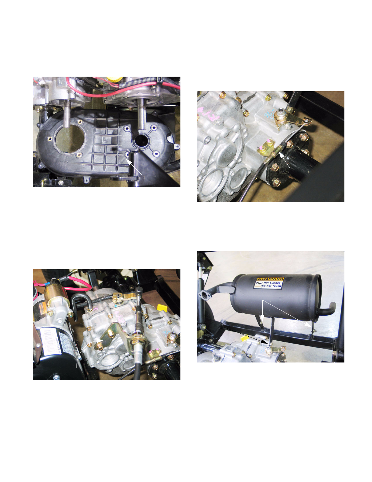
6.6. Lift the bed. Remove the exhaust pipe and the
CVT assembly, including the housing, as
described in the CVT section of this manual.
See Figure 6.6.
CVT housing
Figure 6.6
6.7. Index the forward-neutral-reverse shift arm on
the transaxle to the splined shaft that it mounts
to. Remove the clamp bolt that secures it using
a 10 mm wrench.
6.8. Remove the two bolts that hold the shift cable
bracket to the transaxle using a 12 mm wrench.
See Figure 6.8.
6.10. Remove the two bolts that hold the differential
lock cable bracket to the transaxle using a 10
mm wrench. There will be enough slack in the
cable to permit the barrel end to be disengaged
from the differential lock arm on the transaxle.
See Figure 6.10.
Differential lock
control cable
bracket
Figure 6.10
6.11. Unbolt the muffler from the frame using a pair of
1/2” wrenches. Unbolt the muffler from the transaxle using a 13 mm wrench. See Figure 6.11.
Shift cable bracket
Figure 6.8
6.9. Remove the shift arm from the shaft, and move
the cable out of the way.
Frame mounts
Transaxle mount
Figure 6.11
6.12. Release the parking brake.
21
K&T Saw Shop 606-678-9623 or 606-561-4983
Page 26

Poly Bed 4 X 2 Drive System
www.mymowerparts.com
6.13. Remove and discard the cotter pins securing the
clevis pins into each brake cable clevis/actuator
arm connection. Remove the clevis pins.
See Figure 6.13.
Cotter
pin
Figure 6.13
6.14. Disconnect the red wire with white trace from the
neutral switch, located on the rear surface of the
upper portion of the transaxle housing. The nut
that secures the eyelet to the stud can be
removed using a 7 mm wrench.
6.15. Remove the bolt holding the front of the transaxle to the torque bracket using two 9/16”
wrenches. See Figure 6.15.
Clevis pin
Clevis
6.16. Remove the bolts that fasten the spring mounts
to the engine and transaxle cradle using a pair of
1/2” combination wrenches. See Figure 6.16.
Spring mount
bolts and nuts
Figure 6.16
NOTE: On each side of the cradle there are two
pedestals: one in front of the axle tube, and one
behind. Two bolts fasten each pedestal to the
front or rear of a spring mount.
6.17. Install the drain and fill plugs, remove the drain
pan and lower the bed.
6.18. Lift and safely support the rear of the vehicle.
See Figure 6.18.
Torque bracket
Figure 6.15
NOTE: Lift the vehicle by the rear cross-member
of the engine and transaxle cradle.
22
Figure 6.18
K&T Saw Shop 606-678-9623 or 606-561-4983
Page 27

www.mymowerparts.com
Poly Bed 4 X 2 Drive System
6.19. Jackstands must be placed under the frame, not
the engine/transaxle cradle. See Figure 6.19.
(near C.G. of vehicle)
Jackstands under frame
Figure 6.19
NOTE: The cross member that the bracket for
the dog-bone joint is attached to provides a convenient place for jackstands. It is near the center
of gravity: the entire vehicle will usually balance
on two jackstands at this location. Because of
the teeter-totter effect, the rear wheels will be left
on until the transaxle is removed.
6.20. Remove the bolts that hold the axle tubes to the
engine/transaxle cradle using a pair of 9/16”
wrenches. See Figure 6.20.
6.21. Carefully lower the engine and transaxle cradle,
until the wheels touch the ground.
See Figure 6.21.
Figure 6.21
NOTE: While the transaxle is partially supported
by the cradle, it will remain up-right.
6.22. With a firm grip on the transaxle, lower the jack
completely, tip the front of the transaxle up so
that the housing clears the back of the cradle,
and roll the transaxle clear of the cradle on it’s
own two wheels. See Figure 6.22.
Axle mount bolts
Figure 6.22
Figure 6.20
6.23. With the transaxle completely removed, the Big
23
Country will be stable on the jackstands.
K&T Saw Shop 606-678-9623 or 606-561-4983
Page 28

Poly Bed 4 X 2 Drive System
www.mymowerparts.com
7. TRANSAXLE INSTALLATION NOTES:
7.1. Reverse the removal procedure to install the
transaxle. The following items are tips, reminders, and torque specifications.
7.2. When mounting the transaxle to the cradle:
• Roll the transaxle into position.
• Attach it loosely to the cradle using the eight
bolts through the brackets on the axle tubes.
• Lift the cradle into place against the spring
mounts, and attach it loosely with eight bolts
removed from these attachment points.
• Position the front of the transaxle in the torque
bracket and loosely install the bolt that secures
it.
• Fasten the CVT housing to the transaxle and the
engine.
• Confirm the correct span between the input shaft
and the crankshaft, and confirm that the two
shafts are parallel in vertical and horizontal
planes. The distance between the two shafts
should be 10.35” (26.28 cm).
NOTE: Two small magnetic squares and a
straight-edge can be used to check for parallelism.
• Once accurately in position, tighten all of the fasteners. (See torque table)
• After tightening, double-check poisoning, to confirm that the parts have not shifted.
7.6. Install the CVT:
• Apply a small amount of anti-seize compound to
the input shaft and the crankshaft.
• Install the appropriate spacers on the input shaft
and crankshaft, and install the appropriate keys
in the keyways on the shafts.
NOTE: The drive belt may be postponed on the
pulleys, and installed simultaneously, or it may
be rolled-on after the pulleys are installed.
• Install the driving and driven pulleys on the
crankshaft and input shaft, and secure them with
the washers and left-hand thread bolts.
• Install the belt.
• Install the CVT cover.
7.7. Confirm that the drain plug is tight.
7.8. Fill the transaxle with 68 fl.oz.(2 liters) of API
“GL5” Hypoid gear oil, or confirm the presence
of the correct amount of appropriate gear lube
using the dipstick:
• SAE 90 above 41 deg. f. (5 deg. c.)
• SAE 80 below 41 deg. f. (5 deg. c.)
7.9. Check the torque on the lug nuts.
7.10. In a safe area that is free of obstacles and hazards, check the drive system and brakes for correct operation before returning the vehicle to
service.
7.3. Connect the differential lock cable and attach the
differential lock bracket to the transaxle.
• Confirm correct operation of the differential lock
shift mechanism.
7.4. Connect the forward-neutral-reverse shift arm to
the splined shaft on the transaxle:
• Align the index marks made before removal.
• Secure the arm with the pinch bolt.
7.5. Connect the clevises on the ends of the brake
cable to the brake actuating arms using clevis
pins and new cotter pins.
• Lubricate the clevis pins lightly with anti-seize
compound or white lithium grease.
• Replace the clevis pins if they show signs of
wear.
24
K&T Saw Shop 606-678-9623 or 606-561-4983
Page 29

www.mymowerparts.com
8. LINK ASSEMBLY
Poly Bed 4 X 2 Drive System
Table 1: Drive System Torque Values
Item Torque Note
cradle to axle tubes 17 ft-lb
21 N-m
cradle to spring
mounts
31 ft-lb
42 N-m
torque bracket 31 ft-lb
42 N-m
CVT cover 48 in-lb
5.5 N-m
CVT housing 160 in-lb
18 N-m
driving pulley 31 ft-lb
42 N-m
driven pulley 24 ft-lb
32 N-m
8.1. The link assembly (aka:dogbone joint) connects
the engine and transaxle cradle to the frame of
the Big Country. This joint locates the front of
the cradle, yet allows enough freedom of move-
1
ment that the cradle can swing up and down and
pivot to accommodate suspension travel.
See Figure 8.1.
2
2
3
Link assembly
3
Figure 8.1
diff. lock cable
bracket
78 in-lb
8.8 N-m
shifter cable bracket 18 ft-lb
25 N-m
shifter control arm 78 in-lb
8.8 N-m
lug nuts 25 ft-lb
34 N-m
drain plug 11 ft-lb
15 N-m
NOTE: 1 May be inaccessible with torque
wrench.
NOTE: 2If locking feature on nut is worn, replace
the nut or apply releasable thread-locking compound such as Loctite 242 (blue).
NOTE: 3 Left-hand threads
8.2. If the link assembly becomes worn or damaged,
the front of the engine and transaxle cradle may
shift and clunk, particularly when acceleration or
braking load is applied. To replace the link
assembly, use the following procedure:
8.3. Tilt the passenger seat forward, and lift out the
parcel bin. This will provide easy access to the
link assembly fasteners.
8.4. Open the hood, and disconnect the negative battery cable. Tools will be in close proximity to the
“hot” stud on the starter motor.
8.5. It is not absolutely necessary to support the front
of the engine and transaxle cradle with a jack,
but it may make it easier to relieve any bind on
the bolts that connect the cradle, link assembly,
and frame.
25
K&T Saw Shop 606-678-9623 or 606-561-4983
Page 30

Poly Bed 4 X 2 Drive System
www.mymowerparts.com
8.6. Remove the nut and bolt (top) that connect the
link assembly to the frame using a pair of 15/16”
wrenches. See Figure 8.6.
Figure 8.6
8.7. Remove the nut and bolt (bottom) that connect
the link assembly to the engine and transaxle
cradle using a pair of 19mm wrenches.
9. TRANSAXLE REPAIRS
Axle Assemblies:
NOTE: It is possible to replace axle bearings
and seals without removing the transaxle from
the vehicle. If this is done, inspect the axle
tubes carefully. If the axle tubes have been bent
by over-loading the suspension (static or shock)
then a mis-alignment of the bearings may have
occurred. This misalignment will cause the rapid
demise of the replacement bearings. Overloading constitutes abuse of the vehicle. The resultant damage is NOT warrantable.
NOTE: If the transaxle is being removed with the
anticipation of disassembly, steps can be saved
in the removal process by leaving the brake
drums and wheels attached to each other:
9.1. Remove and discard the cotter pins that secure
the castle nuts on the end of each axle shaft.
9.2. Set the parking brake, and remove the castle
nuts and washers using a 27 mm socket.
See Figure 9.2.
8.8. With the bolts removed, the link can be lifted out
and replaced. See Figure 8.8.
Figure 8.8
8.9. Installation notes:
• Apply anti-seize compound to the bolts so that
they may be easily removed in the future.
Castle nut
Washer
Cotter pin removed
Figure 9.2
9.3. Release the parking brake, and remove the transaxle assembly as described in the “Transaxle
Removal” portion of this manual.
9.4. Slide the brake drums off of the axle shafts without removing them from the wheels.
• Tighten the top nut and bolt to a torque of 100 +
10 ft.-lbs.
• Tighten the bottom nut and bolt to a torque of 40
+
5 ft.-lbs.
K&T Saw Shop 606-678-9623 or 606-561-4983
26
Page 31

www.mymowerparts.com
Poly Bed 4 X 2 Drive System
9.5. After the wheels and brake drums are removed
from the axle shafts, remove the brake shoes as
described in the “Brakes” section of this manual.
See Figure 9.5.
Brake backing plate
with shoes removed
Mounting bolts
Fixed post
Figure 9.5
9.6. Remove the Brake backing plate assembly from
the transaxle using a 17 mm wrench.
See Figure 9.6.
Actuating cam
9.7. Though it is not likely to require disassembly
during brake or transaxle service, it is worth noting that the backing plate is an assembly.
See Figure 9.7.
Dust cover
Structural backing plate
Figure 9.7
9.8. The cam can be removed from the backing
plate. See Figure 9.8.
Backing
plate removed
Figure 9.6
NOTE: This step is not strictly necessary,
depending on the repairs that are to be performed, but makes the transaxle easier to
maneuver on the bench.
K&T Saw Shop 606-678-9623 or 606-561-4983
Figure 9.8
27
Page 32

Poly Bed 4 X 2 Drive System
www.mymowerparts.com
9.9. When placed on the bench, take note of the orientation of the transaxle components. Match
marks will ease the assembly process but the
following relationships are correct:
• The brake backing plates attach with the lever
and cam to the rear of the transaxle.
• The shock absorber mounts on the axle tubes
go toward the front of the transaxle.
• The spring perches are off-set toward the bottom
of the axle tubes.
• The mounting surfaces of the spring perches
should be parallel to the flat mounting surface for
the shift cable bracket.
• The left hand side (differential lock side) axle
tube is shorter than the right hand side (input
shaft side) axle tube.
9.10. Remove the vent tube from the transaxle housing.
9.11. Remove the screw that locates the differential
lock lever in the transaxle housing using an 8mm
wrench. See Figure 9.11.
Pilot on end of screw
seats in groove in
differential lock lever
9.12. Remove the six bolts that secure the flange of
each axle tube to the transaxle housing using a
12mm wrench. See Figure 9.12.
Six bolts on
axle flange
Shock mounts
to front
Figure 9.12
NOTE: Remove the axle tubes one at a time.
9.13. Shock the axle tube with a soft hammer, if necessary to break the sealant bond that may hold
the axle tube to the housing, and separate the
tube from the housing.
NOTE: The axle shaft may or may not come out
with the tube. Neither situation presents a problem.
Parallel
Figure 9.11
9.14. The left side axle shaft passes through the differential lock collar. The dogs on the collar are
driven by dogs on the differential when the differential lock is engaged. See Figure 9.14.
Differential lock
lever
Dogs
Differential
lock collar
Figure 9.14
28
K&T Saw Shop 606-678-9623 or 606-561-4983
Page 33

www.mymowerparts.com
Poly Bed 4 X 2 Drive System
9.15. The axle shaft will slip out of the collar. The
groove on the collar engages the pin on the shift
arm
9.16. The axle shafts should slip-out through the end
of the axle tube that was connected to the transaxle housing. See Figure 9.16.
Seal surface
Shoulder
Figure 9.16
9.17. To take apart the axle assemblies, remove the
circled that holds the sealed bearing in the end
of each axle tube. See Figure 9.17.
9.18. If the axle shaft is stuck in the inner race of the
bearing, the right side shaft can be removed with
the bearing. See Figure 9.18.
Figure 9.18
9.19. The left side axle shaft is thicker in cross section
to the inside of the seal surface than the right
side axle is. The right side axle will not fit
through the seal that is behind the bearing.
See Figure 9.19.
Right side axle shaft
Bearing
Circlip holds bearing
Left side axle shaft
Figure 9.19
Figure 9.17
NOTE: If the bearing in the right side axle shaft
is stubborn, the left side axle can be used to
force it out. Use caution not to damage the ends
of the axle.
29
K&T Saw Shop 606-678-9623 or 606-561-4983
Page 34

Poly Bed 4 X 2 Drive System
www.mymowerparts.com
9.20. Remove the seal from the axle tube.
See Figure 9.20.
Shoulder for bearing
Figure 9.20
NOTE: The oil seal seats against a shoulder in
the tube. Hook the seal removal tool under the
lip of the seal to avoid scratching the bore that
the seal fits in.
9.21. Technical Info. for the Curious:
See Figure 9.21.
Shoulder for seal
Seal
• The necked-down axle shaft spreads the force
over a wider area, allowing the shaft to twist over
a greater portion of its length when torque is
applied to it. This reduces the load on the weakest part of the shaft: the root of the spline.
9.22. Clean the axle tubes, and inspect them for:
• Bends, cracks, or crushes.
• Scratches or damage to mating surfaces.
9.23. Check the bearings for damage: looseness and
coarseness. Check the shafts for damage to the
splines, threads, bearing seat, and seal surface.
9.24. To remove the differential lock arm from the transaxle housing, simply push it down into the bore.
See Figure 9.24.
O-ring
Differential
lock arm
seal
Figure 9.21
• The weakest part of a splined shaft is at the root
of the spline. That is the smallest cross-section
of the shaft and the root of the spline creates
stress risers.
• The right side axle is necked-down in the middle,
to a size that is smaller than the root of the
spline.
Figure 9.24
9.25. Remove and discard the O-ring seal in the upper
groove on the differential lock arm.
NOTE: If the differential lock failed to disengage
under the pressure of the torsion return spring,
and the linkage moves freely, check the fit
between the shaft of the arm and the bore.
NOTE: Symptoms of a differential lock stuck in
the engaged position include squealing tires
when making turns at even modest speeds on
pavement, and complaints that the front end
“plows” or the ability to turn the vehicle in tight
quarters has diminished.
NOTE: Wear limits for differential lock shift
mechanism:
• Maximum groove width is 9.2mm (.36”)
• Minimum shift pin diameter: 8.3mm (.33”)
• Dogs should not have rounded or broken teeth.
30
K&T Saw Shop 606-678-9623 or 606-561-4983
Page 35

www.mymowerparts.com
Poly Bed 4 X 2 Drive System
Transaxle housing and internals:
9.26. Prepare to separate the case: Clean any rust or
burrs from the input shaft with emery cloth, and
remove the spacer if it was not taken off previously. See Figure 9.26.
Input shaft
Spacer
Figure 9.26
9.29. Use the pry-point recesses that are cast into the
housings to separate the the two halves of the
transmission case. See Figure 9.29.
Pry point
Figure 9.29
NOTE: Small pry-bars or brake adjustment
spoons are handy for case separation.
Brake adjuster spoon
9.27. Position the case so that it rests securely with
the input shaft down, and the perimeter bolts that
hold the case halves together facing up.
NOTE: Supports are easily improvised from 4X4
dimensional lumber, or similar items.
9.28. Remove the 16 perimeter bolts using a 10 mm
wrench. See Figure 9.28.
Perimeter bolts
IInput shaft
4X4s
Figure 9.28
9.30. Carefully lift away the right side half of the transmission housing. See Figure 9.30.
Figure 9.30
NOTE: Do not gouge the mating surface
between the two halves of the housing.
NOTE: do not lose or damage the dowel pins
that help align the two halves of the housing.
31
K&T Saw Shop 606-678-9623 or 606-561-4983
Page 36

Poly Bed 4 X 2 Drive System
www.mymowerparts.com
9.31. Clean the left half of the housing, and inspect the
three bearings that reside in it. See Figure 9.31.
Sealed bearing for input hsaft, blind
Ball bearing for red.shaft, blind
Differential
bearing
Figure 9.31
• The largest bearing supports the differential. It
may be driven out of the housing from the outside-in.
9.32. Be certain to remove all of the cleaning solvent
before heating the housing or reassembling the
transaxle. See Figure 9.32.
Clean any solvent
from behind
sealed bearing
Figure 9.32
• The solvent may be present hazards when
heated.
• The nose of the input shaft rides in a sealed
bearing in a blind hole.
• The reduction shaft is supported by an open ball
bearing in a blind hole.
• A blind bearing puller may be necessary to
remove the input shaft bearing and the reduction
shaft bearing.
• Heating the housing evenly to 200 degrees f.
(93 deg. c.) will cause it to expand, making bearing removal and replacement easier. This
should be done in an oven or by immersion in
hot oil. Do NOT heat the housing with a torch.
The un-even application of heat will cause it to
distort.
• The solvent will severely contaminate the gear
lube on assembly, causing a lubrication related
transaxle failure.
• The solvent tends to get trapped behind the
sealed bearing.
9.33. Remove the 25 mm circlip that secures the 51tooth reverse sprocket to the reduction shaft
using a pair of retaining ring pliers.
See Figure 9.33.
Thrust
washer
Reverse
sprocket
Circlip
Figure 9.33
9.34. Remove the thrust washer (17.3mm I.D.X 30mm
O.D.X 1.4mm thick) from the input shaft.
32
K&T Saw Shop 606-678-9623 or 606-561-4983
Page 37

www.mymowerparts.com
Poly Bed 4 X 2 Drive System
9.35. Lift the 51-tooth sprocket off of the reduction
shaft along with the 19-tooth sprocket from the
input shaft and the link-belt reverse chain.
See Figure 9.35.
19-tooth reverse
sprocket
9.36. Remove the washers that are behind the sprockets on the input shaft and reduction shaft.
See Figure 9.36.
51-tooth reverse sprocket
Figure 9.35
9.37. The shift collar is trapped onto the input shaft by
the shift lever. To remove the shift lever, it is
easiest to remove the detent assembly and
safety switch. See Figure 9.37.
Shift collar
Shift lever
Detent
Safety switch
Figure 9.37
9.38. Remove the detent bolt using a 14 mm wrench.
See Figure 9.38.
Input shaft
Reduction shaft
Thick washer
Thin washer Circlip
Figure 9.36
• A very thin washer (28.3mm I.D.X 34mm O.D.X
0.3mm thick) rides between the 51 tooth
sprocket and the circlip on the reduction shaft.
• A thick washer (22.3mm I.D.X 35mm O.D. X
2mm thick) rides between the dogs on the 19tooth sprocket and the shift collar.
Detent ball
Detent spring
(within bolt)
Detent bolt
Sealing washer
Figure 9.38
NOTE: The detent ball and spring will come out
when the bolt is removed. Discard the sealing
washer and replace it with a fresh one on reassembly if it shows any signs of leakage.
9.39. Remove the safety switch using a 14 mm
wrench. Discard the sealing washer and replace
it with a fresh one on reassembly if it shows any
signs of leakage.
33
K&T Saw Shop 606-678-9623 or 606-561-4983
Page 38

Poly Bed 4 X 2 Drive System
www.mymowerparts.com
9.40. Use a magnet to remove the pin that retains the
shift lever. See Figure 9.40.
Retaining pin
Shift lever
Figure 9.40
9.41. After the pin is removed, slide the shift arm into
its bore to retract the pin from the groove in the
shift collar.
9.42. When the pin is clear of the groove, lift the shift
collar off of the input shaft. See Figure 9.42.
9.43. The differential can be easily lifted out of the
transaxle as an assembly, at this point.
See Figure 9.43.
Differential
Figure 9.43
9.44. With the differential removed, the reduction shaft
and 55-tooth gear can be lifted out of the transaxle together. See Figure 9.44.
Reduction shaft
Remove
shift collar
Retract shift arm
Figure 9.42
NOTE: Wear limits for shift mechanism:
• Width of groove in shift collar: 14.30mm (.563”)
maximum.
• Roller on shift arm pin: 13.8mm (.54”) minimum
O.D. 8.2mm (.32”) maximum I.D.
• Pin on shift arm: 7.8mm (.31”) minimum O.D.
55-tooth reduction gear
(forward)
Figure 9.44
9.45. The input shaft can be removed from the case in
a similar manner. It may be necessary to drive it
out with a soft hammer.
34
K&T Saw Shop 606-678-9623 or 606-561-4983
Page 39

www.mymowerparts.com
Poly Bed 4 X 2 Drive System
9.46. Like the input shaft, it will be necessary to clean
any rust from the exterior part of the shift lever
before it is removed. See Figure 9.46.
Figure 9.46
9.47. The shift lever can be removed through the
inside of the housing. there is a roller on the pin
that engages the shift collar. See Figure 9.47.
Shift lever
9.49. Remove and discard the input shaft seal and the
shift lever seal. Replace them with new seals.
See Figure 9.49.
Input shaft seal
Vent
barb
Shift lever seal
Figure 9.49
9.50. Clean and inspect the reduction shaft and 55tooth gear. 28mm circlips are used as positive
stops to position the gears on the shaft. If they
are suspect, replace them. Otherwise they are
best left undisturbed. See Figure 9.50.
28 mm Circlips used for positive stops
Roller
Figure 9.47
9.48. Clean the left side transaxle housing and inspect
the bearings.
• The reduction shaft bearing is in a blind hole,
and will require a blind bearing removal tool to
withdraw from the housing.
• The differential bearing and the input shaft bearing can be driven out.
• As with the right side housing, the even heat of a
200 deg. f.(93 deg c.) oven will loosen the bearings and ease removal. Do NOT us a torch.
Figure 9.50
35
K&T Saw Shop 606-678-9623 or 606-561-4983
Page 40

Poly Bed 4 X 2 Drive System
www.mymowerparts.com
9.51. A 28mm circlip holds the 55-tooth forward gear
to the reduction shaft. If either component
shows wear or damage, remove this clip to separate them. See Figure 9.51.
28 mm Circlip securing gear
Figure 9.51
NOTE: The gear is reversible, but should be
maintained in its original orientation once the
transaxle is broken-in.
9.52. Clean and inspect the input shaft.
9.53. The 24-tooth forward gear, along with a washer
(25.3mm I.D.X 33mm O.D.X 1mm width) is held
on by a 25mm circlip. See Figure 9.53.
9.54. Inspect the bearing surfaces on the input shaft
and 24-tooth forward gear. See Figure 9.54.
Bearing surface
Figure 9.54
NOTE: The bearing surface of the 24-tooth for-
ward gear is very similar to the bearing surface
in the 19-tooth reverse sprocket.
9.55. If the gear, shaft, or circlip show signs of wear or
damage, replace them. When reassembled,
there should be roughly .020” (.50mm) axial
clearance (end play) available at the gear.
See Figure 9.55.
Bearing surface with lube hole
24-tooth forward gear
Thin washer
Circlip
Figure 9.53
Figure 9.55
36
K&T Saw Shop 606-678-9623 or 606-561-4983
Page 41

www.mymowerparts.com
Poly Bed 4 X 2 Drive System
9.56. Clean and inspect the differential assembly.
See Figure 9.56.
Cotter pins
Cross-pin
Recessed
side of gear
Figure 9.56
• The ring gear teeth should not show wear or
damage.
• Differential action should be smooth.
• Cross-pin may be removed for bearing surface
inspection by removing the cotter pins that
secure it.
• The differential housing can be removed from
the ring gear using an 8mm allen wrench.
9.57. If the ring gear is separated from the differential
housing, alignment is maintained by a single
solid dowel pin. See Figure 9.57.
Flat side
of gear
Dowel pin
Differential lock
engagement dogs
9.58. With the differential housing separated from the
ring gear, and the cross-pin removed the miter
gears can be removed from the differential.
9.59. With the cross-pin and miter gears removed, the
bevel gear and the thrust washer can be
removed for inspection or service.
Assembly notes:
9.60. Hardware:
• Replace all o-rings and seals with new ones.
• Replace any removed cotter pins with new ones.
• Replace any removed circlips with new ones.
• Refer to the torque table for fastener assembly
tightness.
9.61. Order of assembly: reverse of disassembly.
• Drive or press bearings by applying force to the
race nearest the greatest resistance.
• Apply a small amount of grease or gear-lube to
any friction bearing surfaces on assembly.
• Confirm proper fit, orientation, and function during the assembly process.
• Ensure that the Transaxle is filled with 2.0L
(within marked range on dipstick when inserted
but not tightened) of API “GL-5” hypoid gear oil
{SAE 90 above 41 deg. f.(5 deg. c.)} or {SAE 80
below 41 deg. f. (5 deg. c.)} prior to operation.
9.62. Sealing:
• Clean all mating surfaces thoroughly before
assembly.
• Mating surfaces should be free of burrs or
gouges.
• Apply a thin bead of sealant such as Loctite 515
(Flange Sealant) or Kawasaki Bond (Liquid Gasket-silver): 92104-002
Dowel pin
Figure 9.57
• Differential lock dogs should not have worn or
damaged teeth.
K&T Saw Shop 606-678-9623 or 606-561-4983
• Do not apply sealant to the O.D. of seals.
• Protect the lips of seals during installation.
• Drive or press seals using a tool that will not
damage the seal.
• Apply a small amount of grease or gear lube to
o-rings and seal lips.
37
Page 42

Poly Bed 4 X 2 Drive System
Table 2: Transaxle Torque
Item Torque Note
www.mymowerparts.com
Ring gear to differential housing
Differential lock shiftarm stop bolt
Differential lock shiftarm mounting nut
Transaxle housing
bolts
Axle tube to transaxle housing
22 ft-lb
29 N-m
87 in-lb
9.8 N-m
78 in-lb
8.8 N-m
78 in-lb
8.8 N-m
18 ft-lb
25 N-m
Detent bolt 27 ft-lb
37 N-m
Safety switch 87 in-lb
9.8 N-m
diff. lock cable
bracket
78 in-lb
8.8 N-m
shifter cable bracket 18 ft-lb
25 N-m
1
2
3
Axle nut (castle nut) 110 ft-lb
145 N-m
lug nuts 25 ft-lb
34 N-m
Brake backing plate
bolts
Note 1: Apply releasable thread-locking compound
such as Loctite 242.
Note 2: The cable attachment arm should be 90
degrees rearward from the shift arm within the transaxle.
Note 3: Confirm proper return action from he torsion
spring.
25 ft-lb
34 N-m
38
K&T Saw Shop 606-678-9623 or 606-561-4983
Page 43

www.mymowerparts.com
Poly Bed 4 X 2 Brake System
Poly Bed 4 X 2 Brake System
ABOUT THIS SECTION:
This section covers brake service and adjustments on
the “poly bed” Utility Vehicle 4 X 2 Model 414
(37AN414J710).
1. MAINTNANCE AND DESCRIPTION OF THE BRAKE SYSTEM:
1.1. It is important that the brakes on the Big Country
vehicle be properly maintained in order for it to
operate safely and dependably. The condition
and operation of the brake system should be
checked on a regular basis:
• A visual inspection of the cables and linkages
should be made, and operational test performed
every 50 hours of operation.
• A complete inspection of the brake system
(including drums and shoes) should be made
every 500 hours or 24 months of operation.
• The initial 50 hour inspection and subsequent
500 hour inspections coincide with the transaxle
fluid change intervals.
• Any brake service needs (repair or adjustment)
should be made before the vehicle is returned to
service.
NOTE: Some early-production versions of this
model may have a stack of bellville washers
between the nut on the pull bolt and the equalizer bracket. If present, the washers and bolt
should be replaced, as described in service bulletin CC-478
1.3. The two cables extend back to the brakes
mounted on the transaxle. See Figure 1.3.
• The cable housings are secured in brackets on
the engine / transaxle cradle.
• The cable cores connect to the brake arms on
the inboard side of the brake backing plates.
1.2. The brake pedal arm lifts up on the pull bolt that
transmits force to the equalizer bracket. The
equalizer bracket distributes the brake pedal
force between the cores of two cables.
See Figure 1.2.
Figure 1.2
Figure 1.3
1.4. Check the condition of the cables, their mounting
hardware and operating mechanisms.
• Jam nuts holding cable to brakce should be
secure.
• Locating clamps should be secure.
• Cable cores should not be fryed or corroded.
Rubber boots should be intact.
• Cable housings should not be kinked, chafed,
burned, crushed, or otherwise damaged.
• Mountings and clevis pins at the back end of teh
cable should be in good condition and properly
secured.
39
K&T Saw Shop 606-678-9623 or 606-561-4983
Page 44

www.mymowerparts.com
Poly Bed 4 X 2 Brake System
1.5. Any significant wear, damage, or binding should
be addressed prior to making an operational
test.
NOTE: the operational test should be performed
in a safe location that is free of traffic, obstacles,
and hazards.
1.6. If the operator has any specific brake performance complaints, these complaints should
direct the visual examination and be confirmed
during the operational test. If the opeator
describes an inherently unsafe condition, a complete inspection should ber performed in lieu of
the operational test.
1.7. Operational Test - check the following points of
performance:
• The brakes should not drag when they are not
applied.
NOTE: An extremely bad axle bearing can
mimic a dragging brake. If the axle shaft does
not run concentric to the axle tube that the brake
is mounted to, the brake drum will rub on the
shoes when the brakes are fully released. This
will produce sluggish vehicle response and a
grinding noise from the bearing.
• When the brakes are applied at speed, there
should be no unusual noises and not pedal pulsation.
• The parking brake should hold the vehicle with a
capacity load on a 22 degree incline.
• It should require 110 lbs +
Kg.) pedal force to apply the parking brake.
10 lbs. (50 Kg. + 5
2. COMPLETE INSPECTION (DRUM AND SHOE REMOVAL) :
2.1. Park the Big Country vehicle on flat level ground.
2.2. To gain access to the front of the brake linkage:
See Figure 2.2.
Figure 2.2
• Release the hood straps, and open the hood.
• Disconnect the Z fitting that attaches the hood
check cable to the hood.
• Remove the hairpin clip that retains the hood
hinge pin in the hood hinge bracket.
• Slide the hood to the left (facing vehicle) and
remove it.
2.3. To gain access to the brakes: See Figure 2.3.
• Braking force should be fairly evenly distributed
between the rear wheels.
1.8. If the Big country utility vehicle does not perform
as described, adjust the brakes as described in
the brakd adjustment section.
1.9. If adjustment does not completely fix the problem, disassemble the brakes as described in the
Complete Inspection section of this manual.
Replace any worn or damaged parts discovered
during inspection.
Figure 2.3
40
K&T Saw Shop 606-678-9623 or 606-561-4983
Page 45

www.mymowerparts.com
Poly Bed 4 X 2 Brake System
• Lift and safely support the back of the Big Country vehicle.
• Remove the rear lug nuts using a 19 mm socket,
and lift off the rear wheels.
• Release the parking brake, if applied.
2.4. Verify the correct orientation of the brake arm on
the brake actuator cam: The clevis pin on the
brake lever should be visible just beyond the
brake drum when viewed from the side, with the
brakes released. See Figure 2.4.
Clevis pin
Brake arm
2.6. Lift up on the curved lip of the locking clip to
release it from the groove in the brake acutator
cam.
2.7. Slide the brake arm off of the splined end of the
brake actuator cam. See Figure 2.7.
Locking clip
Brake acutator
cam
Index marks
(off-set after the
brake arm
is reoriented)
Curved lip
Figure 2.7
Figure 2.4
2.5. If the brake arms are not in this position, they
must be re-oriented: make an index mark with a
paint stick or marking pen across the brake lever
and the boss that it rests against brake backing
plate. This will establish the original position. See Figure 2.5.
Brake arm
(right side)
Index mark
2.8. Rotate brake arm as needed, slide it back onto
the brake actuator cam, and reinstall the clip.
NOTE: It may be necessary to loosen the top
jam nut on the front end of the brake cable housing. This will provide additional slack to allow
brake actuator arm movement.
2.9. To remove the brake drums:
2.10. Remove the cotter pins that secure the hub nuts.
2.11. Using a 27 mm wrench, remove the hub nuts
and washers. See Figure 2.11.
Washer
Cotter pin
Axle shaft
Hub nut
Brake
backing plate
Figure 2.5
K&T Saw Shop 606-678-9623 or 606-561-4983
Brake drum
Figure 2.11
41
Page 46

Poly Bed 4 X 2 Brake System
www.mymowerparts.com
2.12. To remove the brake shoes: pivot the shoes
away from the backing plate. This will reduce
the spring tension.
2.13. Using either a screwdriver or a brake adjusting
spoon, step the shoes over the end of the cam.
See Figure 2.13.
1: Pivot out
2: Step over
Brake actuator cam
Brake shoes
Figure 2.13
2.15. Reassemble the two springs to the new brake
shoes. See Figure 2.15.
Standard shoe thickness: .257” (4.0mm)
Service limit: .040” (1.0 mm)
Figure 2.15
NOTE: All four shoes are the same. They are
not specific to either axle nor to the top or bottom
psoiton on the axles.
2.14. Inspect the bearings, seals, splines, threads,
and cam. See Figure 2.14.
Splines
Threads
Actuator
cam
Figure 2.14
Sealed bearing
NOTE: The springs connect to the outer-most
holes on the shoes.
NOTE: The springs hook outward from the
inside of the top shoe, and inward from the outside of the bottom shoe.
2.16. Place the top brake shoe over the round pivot
point and the flat cam. Allow the top of the brake
shoe to tip away from the backing plate.
2.17. Place the lower shoe against the pivot point and
by slightly stretching the springs install the lower
shoe over the flat cam. See Figure 2.17.
Figure 2.17
42
K&T Saw Shop 606-678-9623 or 606-561-4983
Page 47

www.mymowerparts.com
Poly Bed 4 X 2 Brake System
2.18. Confirm that the shoes and springs are properly
seated. See Figure 2.18.
Correct shoe and
spring installation
Figure 2.18
2.19. Inspect the brake drums: See Figure 2.19.
2.20. Position the brake drums on the axles, then
secure them with the hub nuts and washers.
See Figure 2.20.
Brake drum going on
Washer Nut
2.21. After any brake shoe or drum service, or
re-oreinting of the brake actuator arms, the
brake linkages should be adjusted.
Figure 2.20
Figure 2.19
• The studs should not exhibit any damage.
• The splines should be in good condition.
• The friction surface should be clean.
• The friction surface should not be grooved,
scored, bell-mouthed, or tapered.
• The inside diameter of the brake drum should
not exceed 6.53” (165.75mm).
3. BRAKE ADJUSTMENT (UNDER THE HOOD)
3.1. Adjust the large nuts on the brake cable ends to
draw any slack out of the cables, and to maintain
the equalizer bracket in a horizontal position
using two 7/8” open end wrenches.
See Figure 3.1.
Equalizer bracket
(should be level)
Cable
jam nuts
Figure 3.1
• The casting should not exhibit any damage.
K&T Saw Shop 606-678-9623 or 606-561-4983
43
Page 48

Poly Bed 4 X 2 Brake System
www.mymowerparts.com
3.2. Adjust the nut and jam nut on the bolt that joins
the clevis (pinned to the brake pedal arm) to the
pivot pin that goes through the equalizer bracket.
See Figure 3.2.
Adjustment nut
Jam nut
Figure 3.2
3.3. Place a bathroom scale between your foot and
the brake pedal. Depress the brake pedal and
set the parking brake. It should take approximately 110 pounds +
of pressure on the pedal to reach the point
where the parking brake will engage.
See Figure 3.3.
10 pounds (50 Kg. + 5 Kg.)
3.6. Tighten the hub nuts to 110 ft-lbs. (145 N-m) and
secure each with a new cotter pin.
See Figure 3.6.
Figure 3.6
3.7. Replace the rear wheels and tighten the lug nuts
to 25 foot-pounds (34 N-m).
3.8. After confirming you have the correct brake
pressure, start the vehicle while it is on the jack
stands and test the brakes by accelerating the
engine and applying the brakes.
3.9. With the brakes released, and the engine
turned-off, confirm that the rear wheels rotate
without drag.
Figure 3.3
3.4. After making any necessary adjustment using
the two large jam nuts on the end of each cable,
or the nut and jam nut on the bolt that connects
the clevis to the equlizer link pivot pin, check all
adjustment hardware to confirm that it is tight.
3.5. Set the parking brake.
3.10. Lower the rear wheels to the ground, and perform several test stops in a clear, safe area to
confirm the correct adjustment and operation of
the brake system before returning the Big Country vehicle to service.
• After this initial brake adjustment is performed,
any further brake adjustment should be done
using the large jam nuts on the forward end of
the brake cable.
• If the brake pedal bottoms-out, the adjustment
may be tightened, but pedal effort to apply the
parking brake should not exceed 120 lbs.
• Confirm correct operation of the brakes after
performing any adjustment or service, and check
the tightness of all hardware to ensure ooperator
safety.
44
K&T Saw Shop 606-678-9623 or 606-561-4983
Page 49

www.mymowerparts.com
3.11. Confirm that the parking brake light illuminates
on the instrument panel when the parking brake
is applied, and goes out when the parking brake
is released. See Figure 3.11.
Poly Bed 4 X 2 Brake System
Figure 3.11
3.12. If necessary the parking brake switch can be
adjusted in its slotted mounting bracket.
See Figure 3.12.
Figure 3.12
3.13. If switch adjustment fails to make the parking
brake light work properly, electrical diagnosis is
necessary.
3.14. Install and secure the hood.
K&T Saw Shop 606-678-9623 or 606-561-4983
45
Page 50

Poly Bed 4 X 2 Brake System
www.mymowerparts.com
46
K&T Saw Shop 606-678-9623 or 606-561-4983
Page 51

www.mymowerparts.com
4 X 2 Drive System - (Steel Bed)
4 X 2 Drive System - (Steel Bed)
ABOUT THIS SECTION:
This section covers the drive system and transaxle
used in the Big Country utility vehicle model series 420
and 430. There was also a low-volume series 410 that
used the same transaxle without the differential lock
feature. The information in this section does not specifically cover series 410, but is applicable to it. No other
manual has been written by Cub Cadet specifically for
the non-locking differential version.
1. CUSTOMER RESPONSIBILITIES
• Housing, axle, bearing, or axle tube damage
caused by impact or over-loading constitutes
customer abuse, and is not covered under the
warranty.
• Damaged caused by shock-loading the transmission is not covered under the warranty.
Shock-loading is primarily caused by shifting
between forward and reverse gears without
allowing the vehicle to come to a full stop. This is
only possible if the vehicle is operated abusively
AND the brake interlock switch is out of adjustment.
2. GEAR LUBE
2.1. Service intervals: Initial change: 50 hours
Subsequent changes: 500 hours of 2 years
Check level: every 100 hours.
2.2. The transaxle should contain between 20 and 24
fluid ounces of 80-90 gear lube or SAE 30
engine oil. 80-90 weight gear lube should be
installed at the factory. Cub Cadet Hydraulic
drive system fluid plus is an acceptable premium
alternative.
2.3. To check the gear lube level, park the vehicle
on a flat level surface.
2.4. Clean the area around the rubber fill plug on top
of the transaxle housing.
2.5. Remove the plug.
2.6. Insert and withdraw a clean steel rule or improvised dipstick. See Figure 2.6.
Tape Measure
• Damage caused by a lubrication failure is not
covered under the warranty.
• It is the customer’s responsibility to have any
leaks repaired in a timely fashion.
• The lug nuts should be inspected for looseness
after the first ten hours of operation. Lug nuts
should be tightened to a torque of 55-60 ft.-lbs.
• The brakes are not self-adjusting. It is the customer’s responsibility to maintain them in good
working order and proper adjustment, whether
directly or through an authorized Cub Cadet Servicing Dealer.
• It is the customer’s responsibility to maintain the
vehicle in accordance with the Operator’s Manual. This includes an initial gear lube change
after 50 hours of operation, and changes every
500 hours of operation (or 2 years) thereafter.
• The gear lube level should be checked every
100 hours of operation. At this time a visual
inspection should be made for leaks or damage.
Figure 2.6
2.7. The oil level should be 4 1/2” to 5” down from the
top surface of the housing adjacent to the hole.
2.8. If additional lube is needed, confirm the current
contents of the transaxle, and add more of the
same to reach the specified level.
2.9. If additional fluid is needed, inspect the transaxle
for leaks or damage. If leakage is found, make
any necessary repairs before returning the vehicle to service.
47
K&T Saw Shop 606-678-9623 or 606-561-4983
Page 52

www.mymowerparts.com
4 X 2 Drive System - (Steel Bed)
2.10. A blocked vent can provoke oil leaks. The vent is
located at the top of the transaxle housing. See
Figure 2.10.
Vent
Figure 2.10
2.11. To change the gear lube: Clean the area
around the fill and drain plugs before removing
either.
3. DIAGNOSIS: CONFIRMING TRANSAXLE FAULT
3.1. Get as much information as possible from the
customer regarding symptoms and circumstances.
3.1. Inspect the vehicle for physical damage and
clues regarding the nature and cause of failure.
3.2. Carefully operate the vehicle if possible, to confirm noises and symptoms.
3.3. Eliminate the possibility of problems with the
electronic controls and vacuum actuated shift
mechanism before assuming there is an internal
problem with the transaxle. Isolate the transaxle.
This may be done by operating the transaxle
manually for test purposes. See Figure 3.3.
2.12. Place a drain pan under the transaxle.
2.13. Remove the drain plug at the lower left corner of
the transaxle using a 1/2” wrench. Inspect the
rubber O-ring on the plug, and replace it if it
shows wear.
2.14. Remove the rubber fill plug on top of the transaxle housing. This will allow air to enter the
transaxle faster, which will allow the gear lube to
drain faster.
NOTE: 80-90 weight gear lube is very thick at
low temperatures, and may take considerable
time to drain if the ambient temperature is below
40 degrees farenheit. At low temperatures, operating (driving) the vehicle immediately prior to
draining the oil will warm the oil, making it easier
to drain.
2.15. Install the drain plug and tighten it to a torque of.
2.16. Add 20 to 24 fluid ounces of gear lube.
Figure 3.3
3.4. Confirm that the problem is not in the brake system or the belt drive system.
NOTE: Brake system service and adjustment
procedures can be found in the 2004 Cub Cadet
Technical Service Disc (Form #769-00961).
3.5. If a drive gear (forward or reverse) or the differential lock fail to engage or disengage by manually overriding the shift mechanism, the problem
is likely to fall within the transaxle. Performance
problems such as failure to reach full speed are
likely to caused by engine, brake, or belt/clutch
issues.
48
K&T Saw Shop 606-678-9623 or 606-561-4983
Page 53

www.mymowerparts.com
4 X 2 Drive System - (Steel Bed)
3.6. An extremely bad axle bearing can mimic a
dragging brake. If the axle shaft does not run
concentric to the axle tube that the brake is
mounted to, the brake drum will rub on the shoes
when the brakes are fully released. This will produce sluggish vehicle response and a grinding
noise from the bearing.
3.7. If the problem lies within the external shift mechanism or the controls, diagnostic procedures can
be found in the 2004 Cub Cadet Technical Service Disc.(Form # 769-00961).
3.8. If the gears can be shifted manually (or using the
the gear selector buttons) with the engine off,
but are difficult to shift with the engine running,
there may be excessive belt drag on the input
pulley. Loading the input shaft can bind the
gears, creating too much friction for the shift
mechanism to over-come.
4. DIAGNOSIS AND SERVICE: DRIVE BELT AND CLUTCHES (CVT OR CONTINUOUSLY VARIABLE TRANSMISSION)
4.1. Park the vehicle on a firm level surface, with the
ignition turned off, and lift the load bed to provide
access to the drive system.
4.2. Inspect the belt and clutches (pulleys) for obvious damage and wear. The belt should measure
at least 1.10 (27mm) across the outside (wide)
surface. If it measures less than this it is worn,
and should be replaced. Confirm that the correct belt is on the vehicle: Cub Cadet Part # 75404018A. The outside of the belt should be flat,
not ribbed.
4.3. With the transaxle in neutral, it should be possible to rotate the driven pulley (on the transaxle)
without applying a force of more than 20 inchlbs. to the driving pulley (on the engine). The belt
should slip easily on the driving pulley.
See Figure 4.3.
20 IN-LBS.
Figure 4.3
• A torque wrench with a 3/4” socket on it should
read less than 20 in.-lbs. while rotating the input
shaft.
• If this figure is exceeded, remove the belt and
repeat the test. This will confirm if the bind is
internal or external.
• If the problem is internal, examine the transaxle,
if the problem is external, examine the CVT.
4.4. With the vehicle in neutral, insure that no unsafe
conditions will arise from starting the engine.
4.5. Connect at tachometer to the engine.
49
K&T Saw Shop 606-678-9623 or 606-561-4983
Page 54

www.mymowerparts.com
4 X 2 Drive System - (Steel Bed)
4.6. Start the engine and check idle speed. The
engine should idle at 1,400 RPM +
the idle speed if it is not in this range. If it is
higher, the clutch will drag.
4.7. The idle speed is controlled by the amount of
tension on the small spring on the governor linkage. See Figure 4.7.
Governed
idle Spring
Idle speed = 1,370 RPM
Figure 4.7
4.8. The throttle stop on the carburetor should be set
so that no-load engine speed never falls below
1,000 RPM. See Figure 4.8.
150. Correct
• If the throttle stop is set too low, the engine may
stall when load is suddenly removed at the same
time the throttle is returned to idle.
4.9. If the vehicle fails to reach full speed (20 MPH)
or has lost performance, and the belt is good,
confirm that the engine still achieves it’s specified top-no-load speed and that the CVT
responds accordingly.
4.10. Top-no-load engine speed should be 3,850 RPM
+
150. Confirm this with a tachometer.
See Figure 4.10.
Driven pulley sheaves are
fully separated
TNL
Speed
= 3,870 RPM
Figure 4.10
Linkage
back
pulled
stopagainst
Throttle
stop screw
Figure 4.8
NOTE: It is necessary to remove the air filter
assembly to reach the throttle stop screw.
• If the throttle stop is set too high it will over-ride
the governed idle. This may cause belt drag,
which will interfere with gear selection.
4.11. Watch the travel of the belt as the engine speed
increases from idle speed to top-no-load speed.
4.12. Engine top-no-load speed is adjustable using
the vertical phillips head screw on the governor
linkage. See Figure 4.12.
NOTE: Air filter
removed for clarity
Top-no-load
adjusted herespeed
Figure 4.12
50
K&T Saw Shop 606-678-9623 or 606-561-4983
Page 55

www.mymowerparts.com
4 X 2 Drive System - (Steel Bed)
4.13. At around 1,400 RPM the sheaves of the driving
pulley should begin to close on the belt.
See Figure 4.13.
Idle speed: driving pulley
Belt
Sheaves fully spread apart
4.14. There should be no significant power transmitted
through the belt at idle speed. See Figure 4.14.
sheaves are fully separated,
and belt is riding in the root
of the pulley
Figure 4.13
4.15. As the engine speed increases from idle speed
to roughly 3,000 RPM, the sheaves of the driving
(engine) pulley will close-down on the belt.
See Figure 4.15.
At 3,000 RPM: driving
pulley sheaves are fully
pulled-together, and the
belt is forced to the outer
circumference of
the pulley
Sheaves close together
• In the first increments of travel (closing
sheaves), the driving pulley will begin to transmit
force through the belt.
Figure 4.15
Belt held stationary
with light friction for
the purpose of
demonstration
only.
Figure 4.14
• As the driving pulley increases speed, and the
sheaves are drawn closer together by centrifugal
force acting on weights, the belt is forced outward. As the belt is forced away from the root of
the pulley, to the perimeter, the drive ratio
changes.
• At lower pulley speeds, a “power ratio” exists
between the driving pulley and the driven pulley.
As speed increases, the drive gradually shifts to
a “speed ratio”.
• As the driving pulley tightens the belt, it is drawn
deeper into the sheaves of the spring-loaded
driven pulley. This maintains constant tension
on the belt, and enhances the ratio change.
51
K&T Saw Shop 606-678-9623 or 606-561-4983
Page 56

www.mymowerparts.com
4 X 2 Drive System - (Steel Bed)
4.16. The ratio change should be fully accomplished
by 3,000 RPM. Beyond this speed, increases in
vehicle speed are directly proportional to
increases in engine speed. See Figure 4.16.
Figure 4.16
NOTE: In Figure 4.16 the belt is drawn fully into
the driven pulley by the squeezing action of driving pulley.
5. CVT REMOVAL: DRIVEN PULLEY
5.1. To remove the driven pulley, begin by removing
the bolt that holds it to the input shaft of the transaxle using a 3/4” wrench.
NOTE: If an impact wrench is not available, it
may be necessary to manually place the transmission in Forward gear and set the parking
brake.
5.2. Carefully roll the drive belt off of the driven pulley. See Figure 5.2.
Bolt loosened
4.17. When engine speed is drawn below 3,000 RPM
by a heavy load and/or steep grade, the CVT
pulleys automatically begin to change ratios to
increase available power to the wheels.
4.18. Alignment: correct spacing and alignment of
the engine and transaxle is set at the factory
using special fixtures.
4.19. The transmission is mounted to brackets that
allow little room for adjustment.
4.20. The holes for the engine mounting bolts are
over-sized to accommodate adjustment.
4.21. If belt drag, accellerated belt wear, or loss of top
speed are noticed, particularly after service that
requires engine removal, check the alignment
and spacing.
4.22. Spacing is correct when belt drag torque is correct, as described in paragraph 4.3.
4.23. Alignment can be done visually, using a straightedge.
Figure 5.2
5.3. Slide the pulley off of the input shaft. It may be
necessary to carefully pry on the pulley hub.
See Figure 5.3.
Clutch
Pry Bar
Figure 5.3
5.4. If the driven pulley does not function properly,
replace it as a complete unit.
52
K&T Saw Shop 606-678-9623 or 606-561-4983
Page 57

www.mymowerparts.com
4 X 2 Drive System - (Steel Bed)
5.5. Key points to inspect on the driven pulley are the
ramp surfaces on the cams, and the polymer
buttons that ride against the ramps.
See Figure 5.5.
Buttons
Ramp Surface of Cam
Figure 5.5
• A worn ramp surface on the cam will change the
acceleration and power characteristics of the
drive system.
• A rough ramp surface on the cam will cause
sticking and inconsistent pulley reaction.
6. CVT REMOVAL: DRIVING PULLEY
6.1. Disconnect and ground the spark plug H.T.
leads.
6.2. Carefully pry the plastic plug out of the center of
the clutch cover. See Figure 6.2.
Plastic Plug
Figure 6.2
6.3. Loosen the bolt securing the driving pulley to the
engine crankshaft using a 9/16” wrench.
See Figure 6.3.
• Polymer buttons worn to less than 1/16” may
damage the ramp surface.
5.6. Installation notes for the driven CVT pulley CVT:
• Apply a light coating of anti-seize compound to
the input shaft before pulley installation. Wipe off
any excess.
• Apply a small amount of releasable thread locking compound such as Loctite 242 (blue) to the
threads of the bolt.
• Tighten the bolt to a torque of 60 +
• Re-connect the spark plug leads.
• Test-drive the vehicle before returning it to service.
5.7. Beyond the warranty period, if a dealer chooses
to service a driven clutch, service information
and specialized tools are available from:
Hoffco/Comet Industries
358 NW F Street
Richmond, IN 47374
(765) 966-8161
5 ft.-lbs.
Pulley
Figure 6.3
NOTE: If working without an impact wrench, it
may be necessary to hold the clutch with a strap
wrench. If this is the case, position the strap
wrench around the largest diameter section of
the pulley, where the lip of the cover is attached
to the sheave. This is the strongest point. Holding the pulley there is not likely to damage the
cover.
53
K&T Saw Shop 606-678-9623 or 606-561-4983
Page 58

www.mymowerparts.com
4 X 2 Drive System - (Steel Bed)
6.4. Remove the drive belt.
6.5. After the center bolt is loosened, remove the
three screws that hold the cover onto the driving
pulley.
6.6. Slide the cover off of the driving pulley. There is
not enough clearance to remove the driving pulley with the cover in place. See Figure 6.6.
Drive Pulley
Figure 6.6
6.8. If the driven clutch does not function properly,
replace it as a complete unit.
• Apply a light coating of anti-sieze compound to
the crankshaft before clutch installation. Wipe off
any excess.
• Note that the key extends well beyond the end of
the crankshaft. It may be easiest to install the
key using the following method: Slide the pulley
onto the crankshaft without the key. Position the
key in the keyway in the pulley and apply gentle
inward pressure, then slowly rotate the pulley
until the key slips into the keyway in the crankshaft.
• Apply a small amount of relishable thread locking compound such as Loctite 242 (blue) to the
threads of the bolt.
• Install the bolt and stepped washer, and tighten
the bolt to a torque of 30 +
5 ft.-lbs.
6.7. Remove the center bolt and stepped washer that
secure the driving pulley to the crankshaft, and
slide the pulley off of the crankshaft.
See Figure 6.7.
Crankshaft
Key
Figure 6.7
54
K&T Saw Shop 606-678-9623 or 606-561-4983
Page 59

www.mymowerparts.com
4 X 2 Drive System - (Steel Bed)
7. TRANSAXLE REMOVAL AND REPLACEMENT
The transaxle is carried on the engine/transaxle cradle,
and the entire cradle moves up and down with the
travel of the suspension. It pivots on a dog-bone joint to
allow for some degree of axial twist in relation to the
rest of the chassis, as well as up and down travel. The
engine and transaxle cradle maintains correct alignment and spacing between the engine and the transaxle. The transaxle also mounts directly to the leaf
springs.
7.1. Park the utility vehicle on firm level ground
where there is sufficient room to work around the
sides and rear of the vehicle. Set the parking
brake.
7.2. If working without an impact wrench: loosen the
lug nuts on the rear wheels 1/2 turn each, then
lift the bed and loosen the bolt that secures the
driven pulley to the input shaft of the transaxle.
Both tasks can be accomplished using a 3/4”
socket on a breaker bar.
7.3. Release the parking brake, and lower the bed.
7.4. Disconnect the bottom of both rear shock
absorbers from the brackets on the transaxle
using a 5/8” wrench and 11/16” wrench.
See Figure 7.4.
7.8. Remove the E-clips that secure each brake
cable to the brackets on the transaxle using a
flat-bladed screwdriver or an E-clip removal tool.
See Figure 7.8.
E-Clip
Figure 7.8
7.9. With the E-clips and clevises removed, the brake
cables can be withdrawn from the brackets on
the transaxle and moved out of the way. there is
a flat washer on each cable, just in front of the
bracket.
7.10. Place a drain pan under the transaxle and
remove the drain plug on the bottom left side of
the transaxle housing using a 1/2” wrench.
Remove the rubber plug from the top of the
housing to allow air to enter, for faster draining.
See Figure 7.10.
Rear Shock
Brake Clevis
Figure 7.4
7.5. Loosen the clevis jam nuts on the threaded end
of each brake cable core 1/2 turn using a 1/2”
wrench.
7.6. Remove and discard the cotter pins securing the
clevis pins into each brake cable clevis/actuator
arm connection. Remove the clevis pins.
7.7. Thread the clevises off of each brake cable.
K&T Saw Shop 606-678-9623 or 606-561-4983
Oil Drain Hole
Figure 7.10
7.11. Raise the bed and disconnect the sparkplug
wires.
55
Page 60

www.mymowerparts.com
4 X 2 Drive System - (Steel Bed)
7.12. Carefully roll the drive belt off of the driven pulley
on the transaxle. See Figure 7.12.
Drive Belt
Figure 7.12
7.13. Match-mark the differential lock lever to the
splined shaft that it clamps to.
7.14. Loosen the clamp bolt that pinches the differential lock lever tight on the shaft using a pair of 7/
16” wrenches. Carefully lift the lever off of the
shaft. See Figure 7.14.
7.16. Lift the differential lock actuator and bracket out
of the way. It is not necessary to disconnect the
vacuum lines nor the vent lines.
7.17. Unplug the neutral switch wires from the neutral
switch, located on top of the forward-neutralreverse actuator mounting bracket.
7.18. Remove the screw that connects the forwardneutral-reverse actuator to the shift wedge using
a 1/4” wrench. disconnect the actuator from the
shift wedge. See Figure 7.18.
Shift Wedge
Figure 7.18
Differential Lock Lever
Figure 7.14
NOTE: Alternatively, the cotter pin and clevis pin
that secure the actuator shaft to the lever can be
removed.
7.15. Remove the three bolts that hold the differential
lock actuator(servo) bracket to the transaxle
using a 9/16” wrench.
7.19. Remove the bolt holding the bracket for the forward-neutral-reverse actuator to the side of the
transaxle using a 1/2” wrench.
7.20. Remove the bolts holding the bracket to the top
of the transaxle using a 3/8” wrench and a 7/16”
wrench. See Figure 7.20.
Accumulator
Bracket
Figure 7.20
56
K&T Saw Shop 606-678-9623 or 606-561-4983
Page 61

www.mymowerparts.com
4 X 2 Drive System - (Steel Bed)
7.21. Lift up on the bracket to remove it from the transaxle, complete with the actuator and the vacuum reservoir (the black sphere mounted to the
top of the bracket). It is not necessary to disconnect the vacuum lines from the reservoir or the
actuator.
7.22. Install the drain and fill plugs, remove the drain
pan and lower the bed.
7.23. Lift and safely support the rear of the vehicle.
See Figure 7.23.
7.24. Remove the U-bolts holding each spring to each
axle tube using a 9/16” wrench. See Figure 7.24.
U-Bolts
Figure 7.24
7.25. Lower the transaxle, engine, and cradle to the
ground, so that they rest on the rear wheels.
Leave the jack in position.
Jack Stands
Figure 7.23
NOTE: Jackstands must be placed under the
frame, not the engine/transaxle cradle.
NOTE: The cross member that the bracket for
the dog-bone joint is attached to provides a convenient place for jackstands. It is near the center
of gravity: the entire vehicle will usually balance
on two jackstands at this location. Because of
the teeter-totter effect, the rear wheels will be left
on until the transaxle is removed.
7.26. Remove the previously loosened bolt that holds
the driven pulley to the input shaft of the transaxle.
7.27. Carefully pry the driven pulley off of the shaft.
See Figure 7.27.
Figure 7.27
7.28. Remove the key from the keyway in the input
shaft.
57
K&T Saw Shop 606-678-9623 or 606-561-4983
Page 62

www.mymowerparts.com
4 X 2 Drive System - (Steel Bed)
7.29. Remove the bolt that connects the front of the
transaxle housing to the torque bracket on the
engine/transaxle cradle using a 3/8” wrench and
at 7/16” wrench. See Figure 7.29.
Tire
Torque Bracket
Figure 7.29
7.30. Loosen the mounting bolts that connect the transaxle to the mounting ears on the engine/transaxle cradle.
7.31. Grasp the transaxle by the input shaft to keep it
from tipping forward as the bolts are removed.
Remove the bolts. See Figure 7.31.
7.32. Lower the jack completely, tip the front of the
transaxle up so that the housing clears the hitch
receiver gusset on the cradle, and roll the transaxle clear of the cradle on it’s own two wheels.
See Figure 7.32.
Transaxle
Figure 7.32
7.33. With the transaxle completely removed, the Big
Country will be stable on the jackstands.
See Figure 7.33.
Rotate
Transaxle
Figure 7.31
NOTE: The input shaft will have anti-seize com-
pound on it.
K&T Saw Shop 606-678-9623 or 606-561-4983
Transaxle Cradle
Figure 7.33
58
Page 63

www.mymowerparts.com
4 X 2 Drive System - (Steel Bed)
8. TRANSAXLE INSTALLATION NOTES:
8.1. Reverse the removal procedure to install the
transaxle. The following items are tips, reminders, and torque specifications.
8.2. When mounting the transaxle to the cradle,
attach it loosely to the cradle using the four bolts
through the brackets on the axle tubes. Before
tightening them, position the front of the transaxle in the torque bracket and install the bolt
that secures it. Once, in position, tighten all of
the fasteners.
8.3. When jacking the transaxle and cradle up to
meet the leaf springs, confirm that the locator
dowel on the bottom of each spring is seated in
its hole on the spring perch bracket.
8.4. Apply a small amount of anti-sieze compound to
the input shaft before installing the driven pulley.
8.5. Fill the transaxle with 20-24 fl. oz. of SAE30
engine oil or 80W90 gear lube by pouring it into
the fill hole covered by the black plug. Cub
Cadet Drive System Fluid Plus is and acceptable
premium alternative.
• Differential lock actuator bracket bolts:
• Shift wedge screw: 20 +
• Bracket: f-n-r actuator, vacuum reservoir, and
neutral switch, top:72 +
• Bracket: f-n-r actuator, vacuum reservoir, and
neutral switch, side: 96 +
•U-bolts: 23 +
• Torque bracket bolt: 72 +
• Driven pulley bolt: 80 +
• Lugs: 55-60 ft.-lbs. (NO thread locking compound)
3 ft.-lbs.
5 in.-lbs.
10 in.-lbs.
10 in.-lbs.
10 in.-lbs.
10 ft.-lbs.
8.6. When correctly filled, on level ground, the level
should be 4 1/2” to 5” down, measured from the
top of the casting, adjacent to the hole.
8.7. Double-check brake adjustment before returning
the vehicle to service.
• It should take 50 lbs. of pressure to set the parking brake.
• Once set, the parking brake should be able to
hold the vehicle, loaded to capacity, on a 22
degree grade.
• The brakes should not drag when the pedal is
released.
• One rear wheel should not lock-up before the
other under hard application.
• It may be necessary to pull the slack out of the
cables to install the clevis pins previously
removed.
• Secure the clevis pins with new cotter pins.
8.8. Unless otherwise specified, use releasble thread
locking compound such as Loctite 242 (blue)
and tighten to the following torques:
• Shock absorber bolts: 35 +
• Drain plug: 20 +
• Differential lock lever clamp bolt: 72 +
5 in.-lbs.
5 ft.-lbs.
K&T Saw Shop 606-678-9623 or 606-561-4983
10 in.-lbs.
59
Page 64

www.mymowerparts.com
4 X 2 Drive System - (Steel Bed)
9. LINK ASSEMBLY
9.1. The link assembly (aka:dogbone joint) connects
the engine and transaxle cradle to the frame of
the Big Country. This joint locates the front of
the cradle, yet allows enough freedom of movement that the cradle can swing up and down and
pivot axially to accommodate suspension travel.
See Figure 9.1.
Starter motor
Link Assembly
9.4. Open the hood, and disconnect the negative battery cable. Tools will be in close proximity to the
“hot” stud on the starter motor.
9.5. It is not absolutely necessary to support the front
of the engine and transaxle cradle with a jack,
but it may make it easier to relieve any bind on
the bolts that connect the cradle, link assembly,
and frame.
9.6. Remove the nut and bolt (top) that connect the
link assembly to the frame using a pair of 15/16”
wrenches.
9.7. Remove the nut and bolt (bottom) that connect
the link assembly to the engine and transaxle
cradle using a pair of 19mm wrenches.
9.8. With the bolts removed, the link can be lifted out
and replaced. See Figure 9.8.
Figure 9.1
9.2. If the link assembly becomes worn or damaged,
the front of the engine and transaxle cradle may
shift and clunk, particularly when acceleration or
braking load is applied. To replace the link
assembly, use the following procedure:
9.3. Tilt the passenger seat forward, and lift out the
parcel bin. This will provide easy access to the
link assembly fasteners. See Figure 9.3.
Link assembly
Inset: link
assembly
Figure 9.8
9.9. Installation notes:
• Apply anti-seize compound to the bolts so that
they may be easily removed in the future.
• Tighten the top nut and bolt to a torque of 100 +
10 ft.-lbs.
• Tighten the bottom nut and bolt to a torque of 40
+
5 ft.-lbs.
Figure 9.3
60
K&T Saw Shop 606-678-9623 or 606-561-4983
Page 65

www.mymowerparts.com
4 X 2 Drive System - (Steel Bed)
10. TRANSAXLE ORIENTATION
10.1. The transaxle is a Dana / Spicer model H12
FNR. Before disassembly, become familiar with
and match-mark the components to establish
orientations for assembly.
10.2. This is a bench procedure. For any internal
repairs, the transaxle must be removed from the
vehicle. See Figure 10.2.
Front
Brackets
Brake Clevis
Rear
10.5. The top two holes for the bolts that connect the
left and right halves of the housing will be
vacant. The bracket that supports the vacuum
reservoir, the F-N-R actuator, and the neutral
switch is secured to these points. The bracket is
also bolted to two mounting bosses on the front
of the right side housing.
10.6. If not previously removed, take-off the bracket
for the differential lock actuator using a 9/16”
wrench. It is held by the same bolts that hold the
right side axle tube and differential lock housing
to the transmission housing. The mounting
flange on the bracket should be vertical, toward
the front of the transaxle. See Figure 10.6.
Differential
Lock
Bracket
Figure 10.2
10.3. Viewing the transaxle as it would be oriented in
the utility vehicle, with the input shaft to the left
hand side and the black rubber fill / check plug
facing up, directly above the axle tubes:
10.4. The vent valve is on the top of the right-side
housing. Remove it using a 7/16” wrench.
See Figure 10.4.
Vent
Figure 10.6
10.7. If not previously removed, the differential lock
lever should be parallel to the axle tubes, with
the clamp bolt to the rear when the differential
lock is engaged (lever pulled forward). It may be
necessary to rotate one of the axle shafts while
applying light forward force to the lever to
engage the differential lock. The lever is easily
removed using a pair of 7/16” wrenches.
10.8. The axle tubes are oriented so that the brake
actuators are at the top, and the brake cable
brackets extend toward the front of the vehicle.
The flats on the mounting flanges at the inboard
end of both axle tubes align with the flats on the
housing.
NOTE: The left side axle is roughly 1 3/4”
shorter than the right (differential lock) side.
Figure 10.4
61
NOTE: The axle bearings are greased, with
sealed bearings at each end. They are not lubricated by the oil within the housing.
K&T Saw Shop 606-678-9623 or 606-561-4983
Page 66

www.mymowerparts.com
4 X 2 Drive System - (Steel Bed)
10.9. The F-N-R shift shaft is located on the front surface of the housing. A 5/16” wrench spans the
flats of the double-D shaft, and can be used in
place of the shift wedge. See Figure 10.9.
Detent Set Screw
Shift Shaft
Figure 10.9
10.10.The detent set-screw is located on the front of
the left side housing beneath the shift shaft,
opposite the lower mounting boss for the bracket
that holds the shift actuator, vacuum reservoir,
and neutral switch.
11. TRANSAXLE DISASSEMBLY: AXLE TUBE REMOVAL AND CASE SEPARATION
11.1. With the drained transaxle positioned on a stable
workbench, remove the six bolts that hold the
right axle tube and differential lock housing to
the transaxle housing using a 9/16” wrench.
NOTE: Removing the brakes prior to removing
the axle tubes will reduce their weight, but is not
strictly necessary.
NOTE: It is not strictly necessary to remove the
axle tubes in order to separate the two halves of
the housing, but it will be the path taken for most
service procedures.
11.2. Separate the axle tube from the differential lock
housing. See Figure 11.2.
Differential Lock Shaft
Figure 11.2
11.3. Repeat this procedure to separate the left side
axle tube from the housing.
NOTE: Because the joint between the axle tube
and the differential housing does not need to be
oil-tight. It is sealed with grease.
62
K&T Saw Shop 606-678-9623 or 606-561-4983
Page 67

www.mymowerparts.com
4 X 2 Drive System - (Steel Bed)
11.4. Remove the detent set screw using a straightblade screwdriver. Retrieve the detent ball and
spring from the detent screw bore using a magnet. See Figure 11.4.
Detent Ball and Spring
Magnet
Figure 11.4
11.5. Position the housing differential lock side-up on
4x4 dimensional lumber, or a similar support.
See Figure 11.5.
11.7. Use the square recessed pry-points to separate
the housing halves. See Figure 11.7.
Figure 11.7
11.8. Separate the differential lock housing from the
right side transaxle housing.
NOTE: The sealant is extremely tenacious.
11.9. Disengage the differential lock dog from the pin
on the differential lock shaft. Lift the dog out of
the housing and push the differential lock shaft
out of the differential lock housing.
See Figure 11.9.
4X4’S
Figure 11.5
11.6. Remove the perimeter bolts that fasten the two
housing halves together using a 3/8’ wrench and
a 7/16” wrench.
Differential Lock Shaft
Differential Lock Dog
Differential Lock Housing
Figure 11.9
11.10. Remove the two seals (axle shaft and differential
lock shaft) from the differential lock housing.
They will not be re-used.
11.11. Clean all sealant and lubricants from the housings.
63
K&T Saw Shop 606-678-9623 or 606-561-4983
Page 68

www.mymowerparts.com
4 X 2 Drive System - (Steel Bed)
12. TRANSAXLE DISASSEMBLY: GEAR SET REMOVAL AND DISASSEMBLY
12.1. Carefully lift the differential and ring gear assembly out of the left side housing. Set it aside in a
clean, safe place. See Figure 12.1.
Differential and
Ring Gear Ass’y.
Intermediate Shaft
Input Shaft
Fixed shaft
Left side Housing
Figure 12.1
12.2. Remove the retaining ring that secures the idler
gear to the fixed shaft in the housing.
12.4. Lift the input shaft and thin thrust washer (.030”
thick) from the housing. See Figure 12.4.
.030” Thick Thrust Washer
Figure 12.4
12.5. Lift the thick thrust washer (.110” thick) and final
drive pinion off of the intermediate shaft. Set
gears aside in a clean safe spot, maintaining
sequence (take note of position and orientation).
See Figure 12.5.
Input Shaft
12.3. Lift the following items off of the fixed shaft:
keyed thrust washer, idler gear, and plain thrust
washer (.030” thick). Set them aside in a clean
safe place. See Figure 12.3.
Keyed Thrust Washer
Plain Thrust Washer
Figure 12.3
Retaining
Ring
Idler
Gear
Final Drive Pinion
.110” Thick Thrust Washer
Intermediate Shaft
Figure 12.5
64
K&T Saw Shop 606-678-9623 or 606-561-4983
Page 69

www.mymowerparts.com
4 X 2 Drive System - (Steel Bed)
12.6. Lift the reverse gear off of the intermediate shaft.
See Figure 12.6.
Intermediate
Shaft
Shift Collar
NOTE: The reverse gear has smaller O.D. and
larger I.D. than the forward gear.
NOTE: The recessed side faces the shift collar.
Recessed
Side
Figure 12.6
Reverse Gear
12.8. Remove the intermediate shaft. See Figure 12.8.
Intermediate Shaft
Forward Gear
(Recessed Side
Faces Shift Collar)
Figure 12.8
12.9. Lift the forward gear out of the housing. The forward gear has a smaller I.D. and a larger O.D.
than the reverse gear does. See Figure 12.9.
12.7. Lift the shift collar off of the intermediate shaft
together with the shift rod assembly. The pin on
the shift rod assembly should disengage from
th e s lo t in th e sh if t a ct ua to r a s i t is li ft ed o ut .
See Figure 12.7.
Shift Rod Assembly
Pin
Shift Actuator
Figure 12.7
.110 Thick Thrust Washer
Figure 12.9
NOTE: The recess in the forward gear faces up,
toward the shift collar, the flat side faces the
housing.
12.10.Remove the thick (.110” thick) thrust washer
from case. It may sometimes remain stuck to the
forward gear, because of vacuum and oil adhesion.
65
K&T Saw Shop 606-678-9623 or 606-561-4983
Page 70

www.mymowerparts.com
4 X 2 Drive System - (Steel Bed)
12.11. Push the shift actuator into the case, and
remove it. See Figure 12.11.
Bore for
Shift Shaft
Shift Actuator
Figure 12.11
12.12.Remove the seals from the case. There are
three on the left side housing: input shaft seal,
axle seal, and shift actuator seal. Do not re-use
the seals. See Figure 12.12.
Shift Actuator
Input Shaft
Seal
Seal
Axle
Seal
12.14.The input shaft bearing can be driven out of the
housing. See Figure 12.14.
Input Shaft
Bearing
Figure 12.14
NOTE: The input shaft seal may be pushed
through as well. There is not a shoulder in the
bore.
12.15. The intermediate shaft bearing and the bearings
in the right side housing will require a blind bearing puller and/or judicious application of heat.
See Figure 12.15.
Figure 12.12
12.13.Check the bearings in both sides of the housing
for any signs of damage (looseness, tightness,
discoloration, rough operation). If damage is
found, remove and discard the damaged bearing
or bearings.
NOTE: Only remove the bearings if they are to
be replaced. Do not re-use bearings that have
been removed.
K&T Saw Shop 606-678-9623 or 606-561-4983
Figure 12.15
66
Page 71

www.mymowerparts.com
4 X 2 Drive System - (Steel Bed)
12.16.Careful application of a propane torch (NOT oxyaccetelene), or heating the housing in an oven
for about ten minutes at 250 deg. F. will expand
the alloy housing faster than the steel bearing,
allowing for easy removal of the bearing.
NOTE: An oven that is to be used for food preparation should not be used for transmission
preparation.
12.17.Clean and inspect the gears, shafts, shift collar,
and housings. See Figure 12.17.
12.18.Replace any suspect parts and assemble the
transaxle.
• If the input shaft or the bearings that carry it
have been replaced, test-assemble the housing
without sealant and check shaft end-play with a
dial indicator. Shim it as necessary to obtain
.002 to .006 end play. There is a shim kit
described in the Illustrated Parts List.
• Warming the transaxle housings, or chilling the
bearings prior to installation will ease the process.
• Seal the two halves of the housing together with
a non-silicone based gasket material such as
Loctite 518 (red) sealant.
• On the bolts securing the housing halves
together, use new self-locking nuts or apply a
thread locking compound such as Loctite 242
(blue) to the threads, and tighten them to a
torque of 95 +
• Protect seal lips during shaft installation, and
press them flush with the housings using a seal
driver. See Figure 12.18.
10 in.-lbs.
Figure 12.17
• Visually check the gears for: worn or damaged
teeth, worn holes that engage the dogs on the
shift collar, discoloration, scoring or metal transfer on the recessed surface, or damaged inner
bushings. The gear should be replaced if the
inner bushing is discolored, scored, or non-circular.
• Visually check the shafts for: worn or damaged
teeth, discoloration, or damage to any bearing
surfaces.
• Visually check the shift collar for worn or
rounded dogs, cracks, or discoloration. If there
is significant damage to the shift collar or the
shift collar’s engagement points on the forward
and reverse gears, shift linkage maladjustment
or improper use may be the core problem.
• Inspect the differential assembly. Differential
repair, if necessary, is covered in a separate section.
Figure 12.18
• Install new “O” ring on the drain plug, and tighten
it securely.
• Install the detent ball, spring, and set screw in
their bore. A small quantity of Teflon thread
sealant may be used on the set screw. Tighten it
until a shift torque of 8 to 14 ft.-lbs. is achieved at
the shift actuator assembly.
67
K&T Saw Shop 606-678-9623 or 606-561-4983
Page 72

www.mymowerparts.com
4 X 2 Drive System - (Steel Bed)
13. TRANSAXLE DISASSEMBLY: DIFFERENTIAL
13.1. Position the differential assembly so that it rests
on the differential lock dogs. The nuts on the
ring-gear bolts should face up.
13.2. Remove the four bolts that hold the ring gear to
the differential assembly using a pair of 9/16”
wrenches. See Figure 13.2.
Ring Gear
Differential
Assembly
Figure 13.2
13.3. Lift the ring gear off of the differential.
See Figure 13.3.
Differential Housing
(ring gear removed)
Figure 13.3
13.4. Lift the differential housing (containing the miter
gears) off of the differential housing end plate
(with differential lock dog machined into it).
See Figure 13.4.
NOTE: When installing the ring gear:
• Do not re-use the locking nuts, replace them.
• The bolts must enter the assembly from the differential housing (differential lock dog) side.
• Tighten the bolts to a torque of 55-63 ft.-lbs.
• Do not substitute standard hardware for the ring
gear bolts.
• The ring gear is installed from the miter gear
side of the differential, so that the mounting
flange nests in the deeply recessed side of the
ring gear.
Axle Shaft Miter Gears
Cross-shaft
Miter Gears
Figure 13.4
13.5. The axle shaft miter gear can be lifted out of the
end plate.
13.6. Check the bearing for rough rotation, or any
other signs of damage.
NOTE: If the bearing is removed, it should be
replaced with a new bearing. If the bearing is
good, do not remove it.
68
K&T Saw Shop 606-678-9623 or 606-561-4983
Page 73

www.mymowerparts.com
4 X 2 Drive System - (Steel Bed)
13.7. If it is necessary to remove the bearing, use a
bearing puller. See Figure 13.7.
Bearing
Puller
Figure 13.7
13.8. Position the differential housing so that a flatnosed drift can be used to drive-out the tension
pin that secures the cross-shaft.
13.10.Lift the miter gears and thrust washers out of the
differential housing. See Figure 13.10.
Cross-shaft Miter Gears
Thrust Washers
Figure 13.10
13.11. The axle shaft miter gear, and the thrust washer
that goes beneath it can be lifted out of the end
plate. See Figure 13.11.
13.9. Drive out the pin and remove the cross-shaft.
See Figure 13.9.
Hole
for Pin
Cross-Shaft
Pin
Figure 13.9
Thrust Washer
Figure 13.11
13.12.Check the bearing for rough rotation, or any
other signs of damage.
NOTE: If the bearing is removed, it should be
replaced with a new bearing. If the bearing is
good, do not remove it.
Axle shaft
Miter Gear
69
K&T Saw Shop 606-678-9623 or 606-561-4983
Page 74

www.mymowerparts.com
4 X 2 Drive System - (Steel Bed)
13.13.If it is necessary to remove the bearing, use a
bearing puller. See Figure 13.13.
Gear Puller
Figure 13.13
14. TRANSAXLE: AXLE TUBES
14.1. If brake drum has not already been removed
from the axle tube, perform the following steps:
14.2. Remove the brake drum. See Figure 14.2.
Speed Nut
Brake Drum
Figure 14.2
NOTE: On transaxles that have never had the
brake drum removed, there may be a speed nut
on one of the studs. The speed nut is there for
factory assembly and shipping purposes. It can
be removed and discarded.
14.3. Remove the R-shaped clips that hold the brake
actuator to the brake shoes, and remove the
actuator. See Figure 14.3.
Brake Shoes
R-shaped clips
Figure 14.3
70
K&T Saw Shop 606-678-9623 or 606-561-4983
Page 75

www.mymowerparts.com
4 X 2 Drive System - (Steel Bed)
14.4. Remove the brake shoes:
• Release the small blue tension spring adjacent
to the brake adjuster.
• Remove the brake adjuster
• Pry the tail of each torsion spring over the lip that
it seats behind on the cast brake bracket.
• Lift away the shoes and springs.
14.5. Remove the nuts from the four socket-head cap
screws that hold the brake bracket assembly to
the axle tube using a 1/2” wrench.
See Figure 14.5.
14.6. Slide the axle shaft, bearing, and brake bracket
assembly out of the axle tube. See Figure 14.6.
Figure 14.6
14.7. It may be necessary to use a slide hammer to
draw the bearing race out of the axle tube.
See Figure 14.7.
Figure 14.5
NOTE: The socket head cap screws have a flat
ground on the head. The flat seats against the
axle tube to keep them from rotating. If an allen
wrench is necessary, it will be 1/4”.
Axle Tube
Slide Hammer
Figure 14.7
14.8. There is an axle seal in the tube, beyond the
race. It can be driven out with a long shaft
inserted from the far end of the axle tube.
14.9. To remove the bearing from the axle shaft, it is
necessary to split the pressed on retaining ring
adjacent to the bearing. If the bearing is
removed, it must be replaced with a new one.
71
K&T Saw Shop 606-678-9623 or 606-561-4983
Page 76

www.mymowerparts.com
4 X 2 Drive System - (Steel Bed)
14.10. Drill a small (1/8” or less) pilot hole into the outside edge of the retaining ring. Drill most of the
way through the ring, but do not drill into the axle
shaft. Enlarge the hole with a 1/4” bit.
See Figure 14.10.
Figure 14.10
14.11. Split the ring with a cold chisel. Once the tension on the ring is relieved, it will slide easily off
the axle shaft. See Figure 14.11.
Chisel
Retaining
ring
14.12.The bearing must be pressed off of the shoulder
on the axle. The plastic dust cover may separate from its metal mounting plate in the process.
See Figure 14.12.
Figure 14.12
14.13.Clean and inspect all the components, and
replace any that are damaged.
14.14.Install a new axle bearing inner seal in the axle
tube using a driver that applies force to the outside diameter of the seal. The seal lip should
face in.
14.15.Install a new bearing race in the axle tube.
See Figure 14.15.
Figure 14.11
New bearing race
Seal
Figure 14.15
72
K&T Saw Shop 606-678-9623 or 606-561-4983
Page 77

www.mymowerparts.com
14.16.Clean the axle, apply a small amount of motor oil
or wheel bearing grease to the surface that the
axle bearing outer seal rides on, and install a
new seal onto the axle. The side of the seal with
the embossed words “THIS SIDE OUT” should
face the wheel flange.
4 X 2 Drive System - (Steel Bed)
NOTE: To orient the brake bracket assembly to
the axle tube and dust cover:
• The flats on the inner axle tube mounting flange
face front and rear.
14.17.Position the brake bracket assembly, then the
dust cover assembly on the axle. The dust
cover will not fit inside-out.
14.18.Pack the bearing with good quality wheel bearing grease, and install the bearing on the axle.
See Figure 14.18.
Dust cover
Bearing Retaining ring
Figure 14.18
• The cable bracket extends forward of the axle
tube.
• The large flat bosses that the top of the brake
shoes contact goes to the top.
• The rectangular holes in the dust cover should
be near the flat bosses, for the brake actuator
arm to fit through.
• The right side axle tube is shorter than the left
one, to accommodate the differential lock housing.
• The right side axle shaft has two lengths of
splines separated by about 1 1/2” of shaft.
14.23.When assembling the axle tubes to the housing:
See Figure 14.23.
• Thoroughly clean all traces of old sealant and
lubricants from the mating surfaces.
• Apply a bead of non-silicone based sealant such
as Loctite 518 to the mating surfaces.
• Install each axle tube, and secure them using
the six bolts previously removed.
14.19.Press the retaining ring onto the shoulder that
the axle bearing seats on, so that it holds the
axle bearing snugly in place.
14.20.Lubricate the finished surface near the retaining
ring with motor oil or gear lube.
14.21. Insert the axle into the axle tube.
14.22.Secure the brake bracket assembly and the dust
cover assembly to the axle using the four socket
head cap screws and nuts. Tighten them to a
torque of 200 +
20 in.-lbs. using a 1/2” wrench.
• The three top/front bolts on the right side axle
tube secure the differential lock actuator bracket.
• Tighten the bolts to a torque of 25 to 35 ft.-lbs.
using a 9/16” socket.
Differential lock
actuator bracket
Figure 14.23
73
K&T Saw Shop 606-678-9623 or 606-561-4983
Page 78

www.mymowerparts.com
4 X 2 Drive System - (Steel Bed)
15. IN CRADLE ENGINE SERVICE
NOTE: Basic maintenance, valve adjustment,
and fuel system repair can be easily accomplished without removing the engine from the
vehicle. Any repair that requires the fan cover to
be completely removed from the engine is most
easily performed on the bench, with the engine
removed from the vehicle. Fuel pump service
and valve lash adjustment are two typical procedures that can be performed with the engine in
place.
FUEL PUMP SERVICE
It may be necessary to replace the fuel pump if the following situations exist:
• Fuel pump pressure is less than .5 PSI, and
other factors are eliminated: pinched line, leaky
pick-up, blocked filter, loss of vacuum to pump.
• The fuel pump diaphragm has failed, causing
fuel to enter the crankcase.
NOTE: Fuel pump performance may be checked
without removing the pump.
15.1. Park the vehicle on firm level ground, and raise
the bed to gain access to the engine.
15.2. Lift the four clips that secure the air filter cover.
Remove the cover, pre-filter, and filter.
See Figure 15.2.
15.3. Remove the two screws holding the air filter
base to the fan cover using an 8mm driver.
Remove the two screws that hold the air filter
base to the carburetor using a 10 mm driver.
See Figure 15.3.
Screws
Bracket and
grommet
NOTE: The fan side of the air filter base is also
located by a bracket and rubber grommet.
15.4. Remove the four nuts securing the finger guard
using a 10 mm wrench. Remove the finger
guard.
15.5. Remove the two phillips head screws that hold
the fuel pump cover in place. Move the cover
out of the way, along with the hoses, tubes, and
wires that are secured to it with cable ties.
See Figure 15.5.
Finger guard
Figure 15.3
Figure 15.5
Figure 15.2
74
K&T Saw Shop 606-678-9623 or 606-561-4983
Fuel pump cover:
removed
Page 79

www.mymowerparts.com
4 X 2 Drive System - (Steel Bed)
15.6. Remove the three screws securing the grid
screen to the grid screen holder using a 10 mm
wrench. Remove the grid screen.
See Figure 15.6.
Grid Screen
15.7. Remove the two screws that hold the top of the
fan cover to the engine using a 10 mm wrench.
Install one or two of the nuts that held the finger
guard in place. Thread it on just far enough to
keep the nut from falling off. See Figure 15.7.
Screws
Figure 15.6
15.9. Remove the fuel pump bracket from the intake
manifold using a 10 mm socket.
See Figure 15.9.
Figure 15.9
15.10.Note the position of the hoses that connect to
the fuel pump. Disconnect the hoses, and
remove the fuel pump. See Figure 15.10.
Figure 15.7
15.8. Pull the fan cover out just far enough to provide
access to the fuel pump. The cover will not
come completely off with the engine in place.
K&T Saw Shop 606-678-9623 or 606-561-4983
Figure 15.10
75
Page 80

www.mymowerparts.com
4 X 2 Drive System - (Steel Bed)
15.11. The fuel pump can be tested on the bench using
a hand operated vacuum pump to confirm the
initial tests. See Figure 15.11.
Diaphragm
Chamber Vent
Figure 15.11
15.12.With the vent blocked, the diaphragm should be
able to hold vacuum generated by the hand
pump. See Figure 15.12.
Valve Adjustment
Valve lash adjustment should be checked annually, or
every 300 hours of operation, whichever comes first. If
clatter is heard from the engine during operation, valve
lash should be checked.
15.13.Park the Big country on firm level ground, and
raise the bed to provide access to the engine.
15.14.Allow the engine to cool if it has been run, and
clean any dirt away from the areas surrounding
the valve covers.
15.15.The rear valve cover is easily accessible.
Removing the plenum at the front of the engine
compartment will ease access to the valve cover
on the front cylinder. See Figure 15.15.
Figure 15.12
NOTE: Recommended replacement fuel pump:
BS-808656
Figure 15.15
15.16.Disconnect the high tension leads from the spark
plugs. Remove the Spark plugs using a 13/16”
socket.
15.17.Remove the valve covers using a 10 mm
wrench. Clean the valve covers, and inspect the
valve cover gasket and sealing washer under
the bolt head. Replace them if they are hardened, cracked, or damaged.
76
K&T Saw Shop 606-678-9623 or 606-561-4983
Page 81

www.mymowerparts.com
4 X 2 Drive System - (Steel Bed)
15.18.Rotate the engine crankshaft manually to locate
top dead center (TDC) on the compression
stroke for cylinder #1 (front cylinder).
See Figure 15.18.
• Rotating the crankshaft clockwise (seen from the
fan side of the engine) will produce a puff of air
from the spark plug hole just before this point.
• TDC on the compression stroke can be confirmed by the valves being closed.
• There are timing marks on the fan cover that can
be seen if the finger guard and grid screen are
removed using a 10 mm wrench.
• Cylinder #1 “T” mark is at the upper right hand
side of the fan cover. The mark on the fan
should align with it at TDC co m pres s ion # 1 .
“T” Mark
Timing mark
on fan
15.20.If adjustment is necessary, hold the adjusting nut
with a 14mm wrench, and loosen the jam nut
with a 10mm wrench. Tighten the adjusting nut
until slight drag is felt on the feeler gauge.
Tighten the jam nut against the adjusting nut to
secure it. Double-check the adjustment to make
sure it did not slip during tightening.
See Figure 15.20.
Figure 15.20
Figure 15.18
15.19.Check the clearance between the intake valve
and the rocker arm that acts on it. Check the
clearance between the exhaust valve and the
rocker arm that acts on it.
• Intake valve clearance: 0.15 +
Exhaust valve clearance: 0.20 +
0.02mm (.006”)
0.02mm (.008”)
15.21.Install the valve cover.
15.22.Rotate the crankshaft 270 degrees clockwise to
bring cylinder #2 to TDC position on the compression stroke. The mark on the plastic fan
should align with the upper left “T” mark on the
fan cover. See Figure 15.22.
Figure 15.22
77
K&T Saw Shop 606-678-9623 or 606-561-4983
Page 82

www.mymowerparts.com
4 X 2 Drive System - (Steel Bed)
15.23.Adjust the clearance on cylinder # 2.
15.24.Install the valve cover. See Figure 15.24.
Figure 15.24
15.25.Install both spark plugs, and connect the high
tension leads.
15.26. Lower the bed.
15.27.Test run the vehicle before returning it to service.
78
K&T Saw Shop 606-678-9623 or 606-561-4983
 Loading...