

Page 1
Safe Operation Practices • Set-Up • Operation • Maintenance • Service • Troubleshooting • Warranty
OPERATOR’S MANUAL
Three Stage Snow Thrower
READ AND FOLLOW ALL SAFETY RULES AND INSTRUCTIONS IN THIS MANUAL
BEFORE ATTEMPTING TO OPERATE THIS MACHINE.
FAILURE TO COMPLY WITH THESE INSTRUCTIONS MAY RESULT IN PERSONAL INJURY.
P. O. Box 1386, 97 KENT AVENUE, KITCHENER, ON N2G 4J1
Printed In USA
WARNING
769-09096B
06.19.14
Page 2

To The Owner
Thank You
Thank you for purchasing your new equipment. It was carefully
engineered to provide excellent performance when properly
operated and maintained.
Please read this entire manual prior to operating the equipment.
It instructs you how to safely and easily set up, operate and
maintain your machine. Please be sure that you, and any other
persons who will operate the machine, carefully follow the
recommended safety practices at all times. Failure to do so could
result in personal injury or property damage.
All information in this manual is relative to the most recent
product information available at the time of printing. Review
this manual frequently to familiarize yourself with the machine,
its features and operation. Please be aware that this Operator’s
Manual may cover a range of product specifications for
various models. Characteristics and features discussed and/or
illustrated in this manual may not be applicable to all models.
Table of Contents
1
The manufacturer reserves the right to change product
specifications, designs and equipment without notice and
without incurring obligation.
If you have any problems or questions concerning the machine,
phone your local service dealer or contact us directly. Customer
Support telephone numbers, website address and mailing
address can be found on this page. We want to ensure your
complete satisfaction at all times.
Throughout this manual, all references to right and left side of the
machine are observed from the operating position.
The engine manufacturer is responsible for all engine-related
issues with regards to performance, power-rating, specifications,
warranty and service. Please refer to the engine manufacturer’s
Owner’s/Operator’s Manual, packed separately with your
machine, for more information.
Safe Operation Practices ........................................ 3
Assembly & Set-Up .................................................. 7
Controls ...................................................................12
Operation ................................................................15
Service .....................................................................19
Troubleshooting .....................................................21
Replacement Parts ................................................ 22
Warranty ................................................................ 23
Maintenance & Adjustment .................................16
Record Product Information
Before setting up and operating your new equipment, please
locate the model plate on the equipment and record the
information in the provided area to the right. You can locate the
model plate by standing at the operator’s position and looking
down at the rear of the frame. This information will be necessary,
should you seek technical support via our web site, Customer
Support Department, or with a local authorized service dealer.
Model NuMber
Serial NuMber
Customer Support
Please do
If you have difficulty assembling this product or have any questions regarding the controls, operation, or maintenance of
this machine, you can seek help from the experts. Choose from the options below:
NOT
return the unit to the retailer from which it was purchased, without first contacting Customer Support.
◊ Visit our web at www.cubcadet.ca
◊ Locate your nearest dealer from Customer Support: 1-800-668-1238
◊ Contact Cub Cadet • P.O. Box 1386 • 97 Kent Avenue • Kitchener, Ontario, Canada • N2G 4J1
2
Page 3
Important Safe Operation Practices
WARNING! This symbol points out important safety instructions which, if not followed,
could endanger the personal safety and/or property of yourself and others. Read and follow
all instructions in this manual before attempting to operate this machine. Failure to comply
with these instructions may result in personal injury.
When you see this symbol. HEED ITS WARNING!
CALIFORNIA PROPOSITION 65
WARNING! Engine Exhaust, some of its constituents, and certain vehicle components
contain or emit chemicals known to State of California to cause cancer and birth defects
or other reproductive harm.
DANGER: This machine was built to be operated according to the safe operation practices in
this manual. As with any type of power equipment, carelessness or error on the part of the
operator can result in serious injury. This machine is capable of amputating fingers, hands,
toes and feet and throwing foreign objects. Failure to observe the following safety
instructions could result in serious injury or death.
2
Training
1. Read, understand, and follow all instructions on the
machine and in the manual(s) before attempting to
assemble and operate. Keep this manual in a safe place for
future and regular reference and for ordering replacement
parts.
2. Be familiar with all controls and their proper operation.
Know how to stop the machine and disengage them
quickly.
3. Never allow children under 14 years of age to operate this
machine. Children 14 and over should read and understand
the instructions and safe operation practices in this manual
and on the machine and be trained and supervised by an
adult.
4. Never allow adults to operate this machine without proper
instruction.
5. Thrown objects can cause serious personal injury. Plan
your snow-throwing pattern to avoid discharge of material
toward roads, bystanders and the like.
6. Keep bystanders, pets and children at least 75 feet from the
machine while it is in operation. Stop machine if anyone
enters the area.
7. Exercise caution to avoid slipping or falling, especially
when operating in reverse.
Preparation
Thoroughly inspect the area where the equipment is to be used.
Remove all doormats, newspapers, sleds, boards, wires and other
foreign objects, which could be tripped over or thrown by the
auger/impeller.
1. Always wear safety glasses or eye shields during operation
and while performing an adjustment or repair to protect
your eyes. Thrown objects which ricochet can cause serious
injury to the eyes.
2. Do not operate without wearing adequate winter outer
garments. Do not wear jewelry, long scarves or other loose
clothing, which could become entangled in moving parts.
Wear footwear which will improve footing on slippery
surfaces.
3. Use a grounded three-wire extension cord and receptacle
for all machines with electric start engines.
4. Adjust auger housing height to clear gravel or crushed rock
surfaces.
5. Disengage all control levers before starting the engine.
6. Never attempt to make any adjustments while engine is
running, except where specifically recommended in the
operator’s manual.
7. Let engine and machine adjust to outdoor temperature
before starting to clear snow.
3
Page 4

Safe Handling of Gasoline
To avoid personal injury or property damage use extreme care
in handling gasoline. Gasoline is extremely flammable and the
vapors are explosive. Serious personal injury can occur when
gasoline is spilled on yourself or your clothes which can ignite.
Wash your skin and change clothes immediately.
a. Use only an approved gasoline container.
b. Extinguish all cigarettes, cigars, pipes and other
sources of ignition.
c. Never fuel machine indoors.
d. Never remove gas cap or add fuel while the engine is
hot or running.
e. Allow engine to cool at least two minutes before
refueling.
f. Never over fill fuel tank. Fill tank to no more than ½
inch below bottom of filler neck to provide space for
fuel expansion.
g. Replace gasoline cap and tighten securely.
h. If gasoline is spilled, wipe it off the engine and
equipment. Move machine to another area. Wait 5
minutes before starting the engine.
i. Never store the machine or fuel container inside
where there is an open flame, spark or pilot light
(e.g. furnace, water heater, space heater, clothes
dryer etc.).
j. Allow machine to cool at least 5 minutes before
storing.
k. Never fill containers inside a vehicle or on a truck
or trailer bed with a plastic liner. Always place
containers on the ground away from your vehicle
before filling.
l. If possible, remove gas-powered equipment from
the truck or trailer and refuel it on the ground. If this
is not possible, then refuel such equipment on a
trailer with a portable container, rather than from a
gasoline dispenser nozzle.
m. Keep the nozzle in contact with the rim of the fuel
tank or container opening at all times until fueling is
complete. Do not use a nozzle lock-open device.
Operation
1. Do not put hands or feet near rotating parts, in the auger/
impeller housing or chute assembly. Contact with the
rotating parts can amputate hands and feet.
2. The auger/impeller control lever is a safety device. Never
bypass its operation. Doing so makes the machine unsafe
and may cause personal injury.
3. The control levers must operate easily in both directions
and automatically return to the disengaged position when
released.
4. Never operate with a missing or damaged chute assembly.
Keep all safety devices in place and working.
5. Never run an engine indoors or in a poorly ventilated area.
Engine exhaust contains carbon monoxide, an odorless
and deadly gas.
6. Do not operate machine while under the influence of
alcohol or drugs.
7. Muffler and engine become hot and can cause a burn. Do
not touch. Keep children away.
8. Exercise extreme caution when operating on or crossing
gravel surfaces. Stay alert for hidden hazards or traffic.
9. Exercise caution when changing direction and while
operating on slopes. Do not operate on steep slopes.
10. Plan your snow-throwing pattern to avoid discharge
towards windows, walls, cars etc. Thus, avoiding possible
property damage or personal injury caused by a ricochet.
11. Never direct discharge at children, bystanders and pets or
allow anyone in front of the machine.
12. Do not overload machine capacity by attempting to clear
snow at too fast of a rate.
13. Never operate this machine without good visibility or light.
Always be sure of your footing and keep a firm hold on the
handles. Walk, never run.
14. Disengage power to the auger/impeller when transporting
or not in use.
15. Never operate machine at high transport speeds on
slippery surfaces. Look down and behind and use care
when backing up.
16. If the machine should start to vibrate abnormally, stop
the engine, disconnect the spark plug wire and ground it
against the engine. Inspect thoroughly for damage. Repair
any damage before starting and operating.
17. Disengage all control levers and stop engine before you
leave the operating position (behind the handles). Wait
until the auger/impeller comes to a complete stop before
unclogging the chute assembly, making any adjustments,
or inspections.
18. Never put your hand in the discharge or collector openings.
Always use the clean-out tool provided to unclog the
discharge opening. Do not unclog chute assembly while
engine is running. Shut off engine and remain behind
handles until all moving parts have stopped before
unclogging.
19. Use only attachments and accessories approved by the
manufacturer (e.g. wheel weights, tire chains, cabs etc.).
20. When starting engine, pull cord slowly until resistance
is felt, then pull rapidly. Rapid retraction of starter cord
(kickback) will pull hand and arm toward engine faster than
you can let go. Broken bones, fractures, bruises or sprains
could result.
21. If situations occur which are not covered in this manual, use
care and good judgment. Contact Customer Support for
assistance and the name of your nearest servicing dealer.
4 Section 2 — impo rtant Safe operation practiceS
Page 5

Clearing a Clogged Discharge Chute
Hand contact with the rotating impeller inside the discharge
chute is the most common cause of injury associated with snow
throwers. Never use your hand to clean out the discharge chute.
To clear the chute:
1. SHUT THE ENGINE OFF!
2. Wait 10 seconds to be sure the impeller blades have
stopped rotating.
3. Always use a clean-out tool, not your hands.
Maintenance & Storage
1. Never tamper with safety devices. Check their proper
operation regularly. Refer to the maintenance and
adjustment sections of this manual.
2. Before cleaning, repairing, or inspecting machine
disengage all control levers and stop the engine. Wait until
the auger/impeller come to a complete stop. Disconnect
the spark plug wire and ground against the engine to
prevent unintended starting.
3. Check bolts and screws for proper tightness at frequent
intervals to keep the machine in safe working condition.
Also, visually inspect machine for any damage.
4. Do not change the engine governor setting or over-speed
the engine. The governor controls the maximum safe
operating speed of the engine.
5. Snow thrower shave plates and skid shoes are subject to
wear and damage. For your safety protection, frequently
check all components and replace with original equipment
manufacturer’s (OEM) parts only. “Use of parts which do
not meet the original equipment specifications may lead to
improper performance and compromise safety!”
6. Check control levers periodically to verify they engage
and disengage properly and adjust, if necessary. Refer
to the adjustment section in this operator’s manual for
instructions.
7. Maintain or replace safety and instruction labels, as
necessary.
8. Observe proper disposal laws and regulations for gas, oil,
etc. to protect the environment.
9. Prior to storing, run machine a few minutes to clear snow
from machine and prevent freeze up of auger/impeller.
10. Never store the machine or fuel container inside where
there is an open flame, spark or pilot light such as a water
heater, furnace, clothes dryer etc.
11. Always refer to the operator’s manual for proper
instructions on off-season storage.
12. Check fuel line, tank, cap, and fittings frequently for cracks
or leaks. Replace if necessary.
13. Do not crank engine with spark plug removed.
14. According to the Consumer Products Safety Commission
(CPSC) and the U.S. Environmental Protection Agency (EPA),
this product has an Average Useful Life of seven (7) years,
or 60 hours of operation. At the end of the Average Useful
Life have the machine inspected annually by an authorized
service dealer to ensure that all mechanical and safety
systems are working properly and not worn excessively.
Failure to do so can result in accidents, injuries or death.
Do not modify engine
To avoid serious injury or death, do not modify engine in any
way. Tampering with the governor setting can lead to a runaway
engine and cause it to operate at unsafe speeds. Never tamper
with factory setting of engine governor.
Notice Regarding Emissions
Engines which are certified to comply with California and federal
EPA emission regulations for SORE (Small Off Road Equipment)
are certified to operate on regular unleaded gasoline, and
may include the following emission control systems: Engine
Modification (EM), Oxidizing Catalyst (OC), Secondary Air
Injection (SAI) and Three Way Catalyst (TWC) if so equipped.
Spark Arrestor
WARNING! This machine is equipped with an
internal combustion engine and should not be used
on or near any unimproved forest-covered, brush
covered or grass-covered land unless the engine’s
exhaust system is equipped with a spark arrester
meeting applicable local or state laws (if any).
If a spark arrestor is used, it should be maintained in effective
working order by the operator.
A spark arrestor for the muffler is available through your nearest
engine authorized service dealer.
5Section 2 — impo rtant Safe operation practiceS
Page 6
Safety Symbols
This page depicts and describes safety symbols that may appear on this product. Read, understand, and follow all instructions on the
machine before attempting to assemble and operate.
Symbol Description
READ THE OPERATOR’S MANUAL(S)
Read, understand, and follow all instructions in the manual(s) before attempting to
assemble and operate.
WARNING— ROTATING BLADES
Keep hands out of inlet and discharge openings while machine is running. There are rotating
blades inside.
WARNING— ROTATING BLADES
Keep hands out of inlet and discharge openings while machine is running. There are rotating
blades inside.
WARNING— ROTATING AUGER
Do not put hands or feet near rotating parts, in the auger/impeller housing or chute
assembly. Contact with the rotating parts can amputate hands and feet.
WARNING—THROWN OBJECTS
This machine may pick up and throw objects which can cause serious personal injury.
WARNING—GASOLINE IS FLAMMABLE
Allow the engine to cool at least two minutes before refueling.
WARNING— CARBON MONOXIDE
Never run an engine indoors or in a poorly ventilated area. Engine exhaust contains carbon
monoxide, an odorless and deadly gas.
WARNING— ELECTRICAL SHOCK
Do not use the engine’s electric starter in the rain.
WARNING— HOT SURFACE
Engine parts, especially the muffler, become extremely hot during operation. Allow engine
and muffler to cool before touching.
WARNING! Your Responsibility—Restrict the use of this power machine to persons who read, understand and
follow the warnings and instructions in this manual and on the machine.
6 Section 2 — impo rtant Safe operation practiceS
SAVE THESE INSTRUCTIONS!
Page 7

Assembly & Set-Up
IMPORTANT: The snow thrower is shipped with oil and WITHOUT GASOLINE. After assembly, refer to separate engine manual for
proper fuel and engine oil recommendations.
NOTE: Remove all loose parts and any packing material before assembling.
NOTE: References to right or left side of the snow thrower are determined from behind the unit in the operating position.
NOTE: This Operator’s Manual covers several models, handle
panels, lights and chute cranks are some features that may vary
by model. Not all features referenced (or engines pictured) in
this manual are applicable to all snow thrower models.
NOTE: Replacement auger shear pins are included with this
manual (or stowed in the plastic handle panel). Refer to Augers in
the Maintainance Section for more information regarding shear
pin replacement.
NOTE: Some models with electric start are equipped with an
extension cord fastened with a cable tie to the rear of the auger
housing for shipping purposes. Cut the cable tie and remove it
before operating the snow thrower.
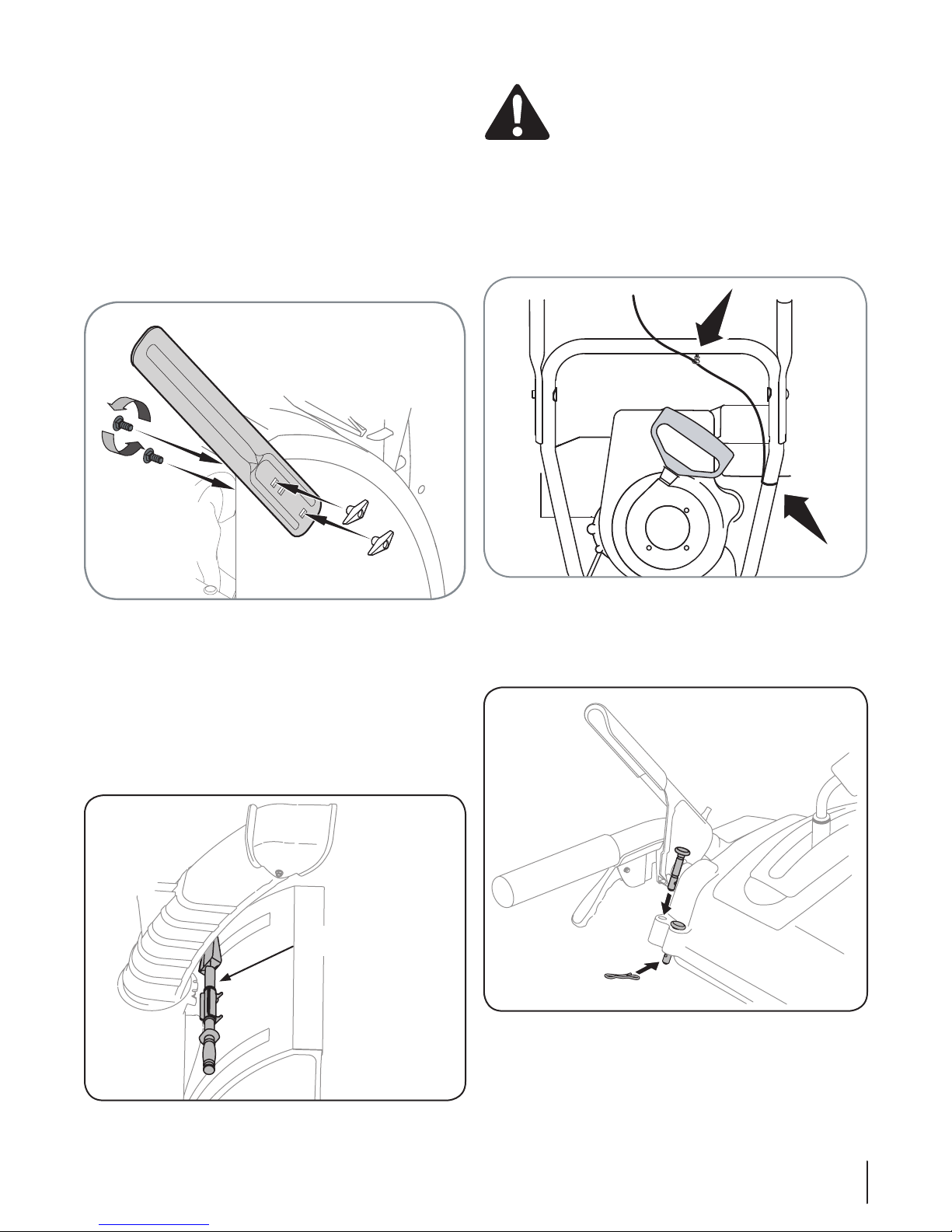
Handle Assembly
• Place the shift lever in the Forward-6 position.
• Observe the lower rear area of the snow thrower to be sure
both cables are aligned with roller guides. See Fig. 3-1. Pull
up on the upper handle, align the upper handle with the
lower handle. See Fig. 3-2.
• Secure the handle by tightening the plastic wing knob
located on both the left and right sides of the handle.
Remove and discard any rubber bands, if present. They are
for packaging purposes only.
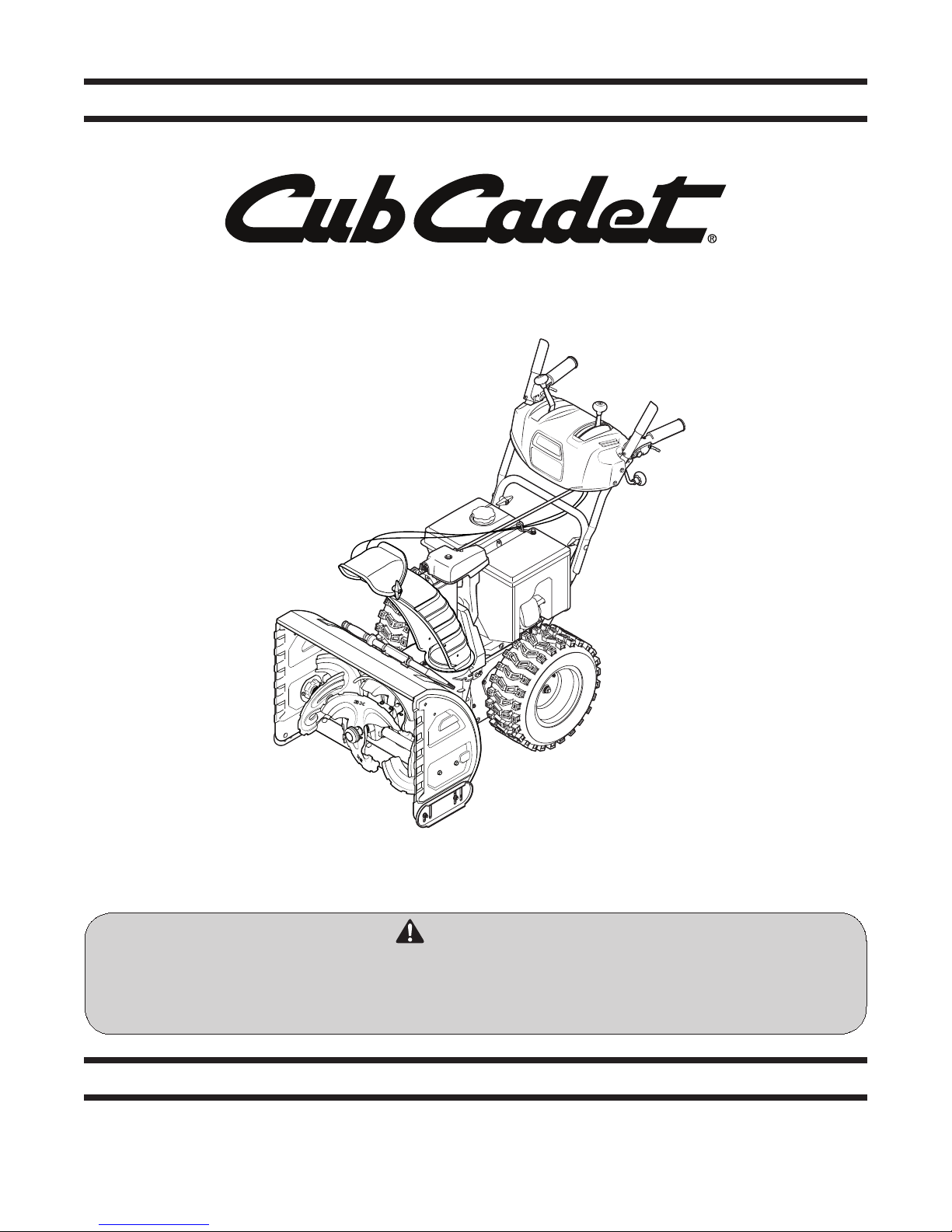
Chute Assembly
• Remove wing nut and hex screw from chute control
assembly and clevis pin and cotter pin from chute support
bracket. See Fig. 3-3. Position the chute assembly (forwardfacing) over the chute base.
Fig. 3-2
3
Fi g. 3-1
Fig. 3-3
7
Page 8
• Place chute assembly onto chute base and secure chute
b
a
control assembly to chute support bracket with clevis pin and
cotter pin removed earlier. See Fig. 3-4.
Fig. 3-4
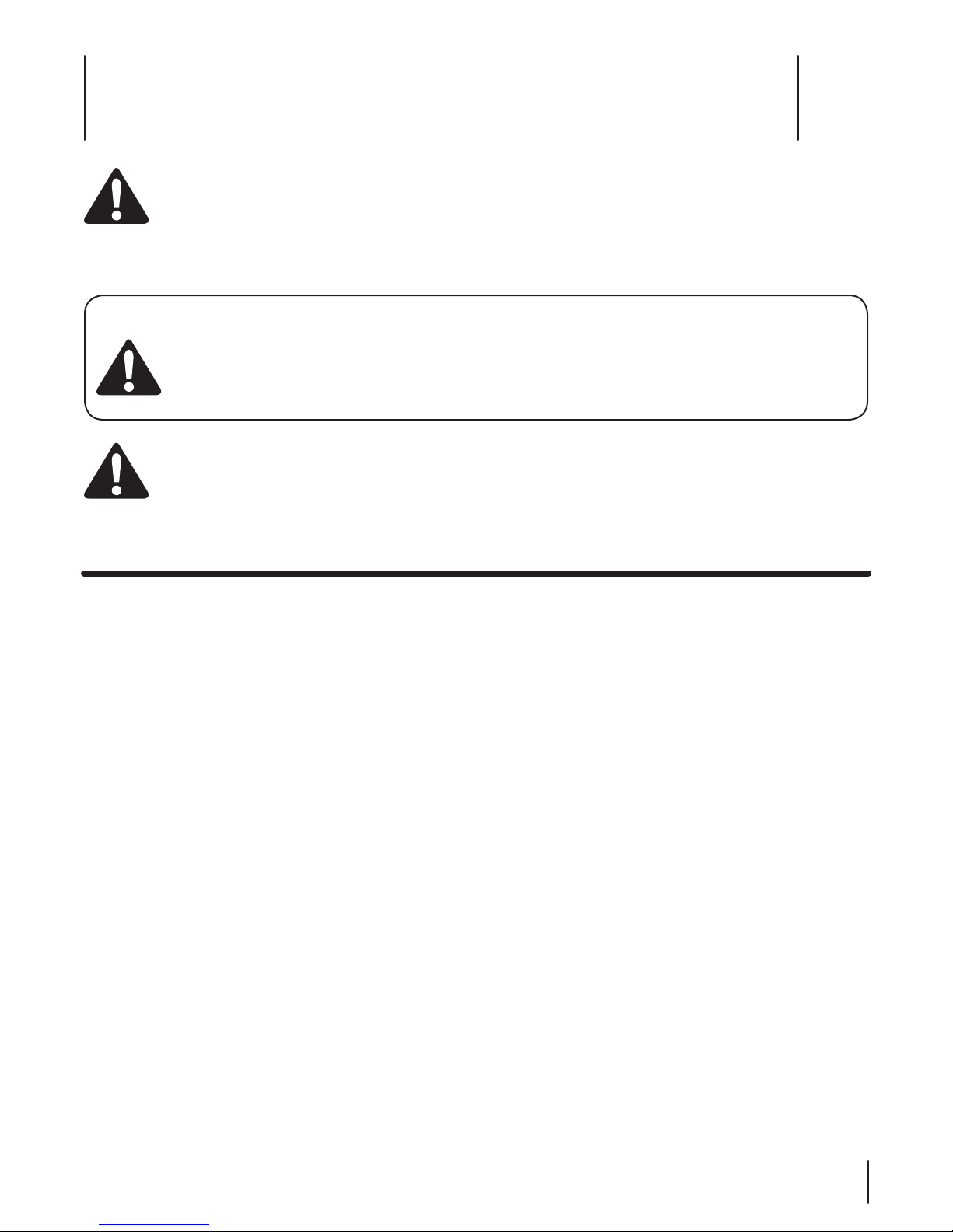
• Finish securing chute control assembly to chute support
bracket with wing nut and hex screw removed earlier. See
Fig. 3-5.
Fig. 3-6
Fig. 3-5
• Guide the chute crank rod through the bracket located on
the rear of the handle panel See Fig. 3-6.
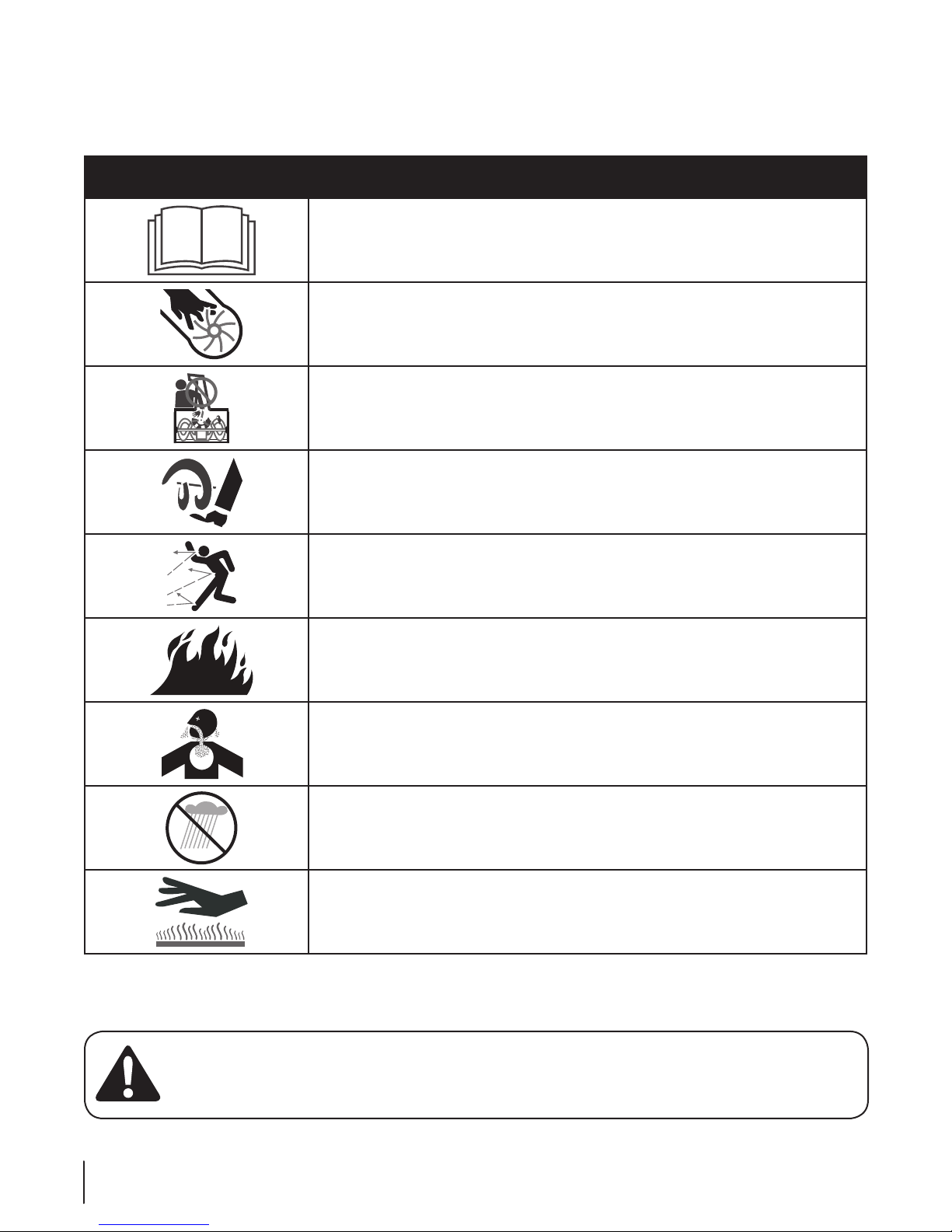
a. Remove the cotter pin and insert the chute crank rod
into the connector on the chute control assembly.
See Fig. 3-7.
b. Align the hole in the chute crank rod with the hole
in the connector, secure with cotter pin previously
removed.
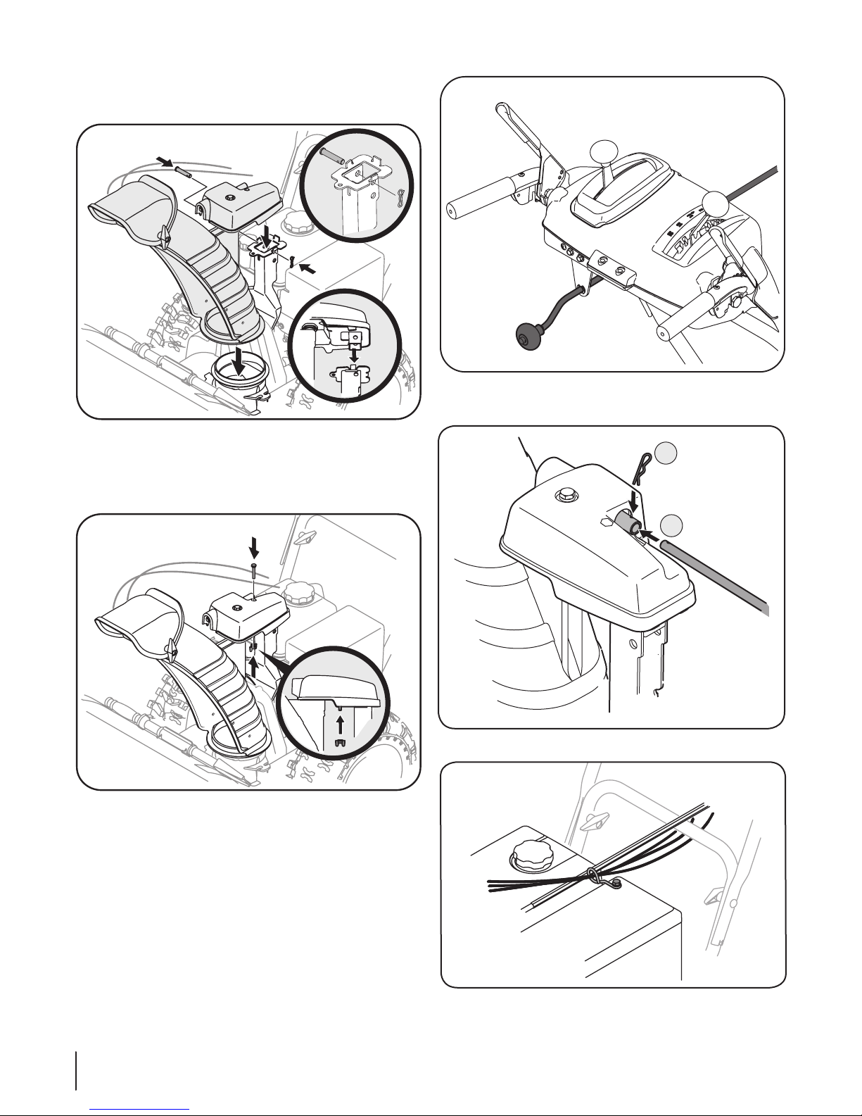
• Check that all cables are properly routed through the cable
guide on the right side of the chute crank rod. See Fig. 3-8.
8 Section 3— ASSe mbly & Set-Up
Fig. 3-7
Fig. 3-8
Page 9
Drift Cutters (If Equipped)
Chute Clean-Out
Too l
Drift cutters should be used when operating the snow thrower in
heavy drift conditions.
• On models so equipped, drift cutters and hardware are
assembled to the auger housing inverted.
• Remove the carriage bolts and wingnuts securing the drift
cutters to the housing.
• Reposition drift cutters so they face forward as shown
in Fig. 3-9. Secure with hardware previously removed,
wingnuts should be fastened on the outside of the
housing as shown.
WARNING: Never use your hands to clean snow
and ice from the chute assembly or auger housing.
Lamp Wiring Harness (If equipped))
The post on the cable tie attaching the lamp wiring harness to
the lower handle should be plugged into the hole in the lower
handle. Pull the slack portion of the wiring harness through the
cable tie to prevent interference with the recoil starter handle.
See Fig. 3-11.
Fig. 3-9
Clean-Out Tool
The clean-out tool is mounted to the rear of the auger housing
and is designed to clear a clogged chute. Refer to page 14 for
instructions on how to properly use it.
NOTE: This item is fastened with a cable tie to the rear of the
auger housing at the factory. Cut the cable tie before operating
the snow thrower. See Fig. 3-10.
Fi g. 3-11
Shear Pins Storage (if so equipped)
On some models an area for convenient shear pin storage is
located at the rear of the dash panel. See Fig. 3-12.
Fi g. 3-12
Fi g. 3-10
9Section 3 — ASSemb ly & Set-Up
Page 10
Tire Pressure
The tires are over-inflated for shipping purposes. Check the tire
pressure before operating the snow thrower. Refer to the tire side
wall for tire manufacturer’s recommended psi and deflate (or
inflate) the tires as necessary.
WARNING: Under any circumstance do not exceed
manufacturer’s recommended psi. Equal tire
pressure should be maintained at all times. Excessive
pressure when seating beads may cause tire/rim
assembly to burst with force sufficient to cause
serious injury. Refer to sidewall of tire for
recommended pressure.
NOTE: Equal tire pressure is to be maintained at all times for
performance purposes.
Adjustment
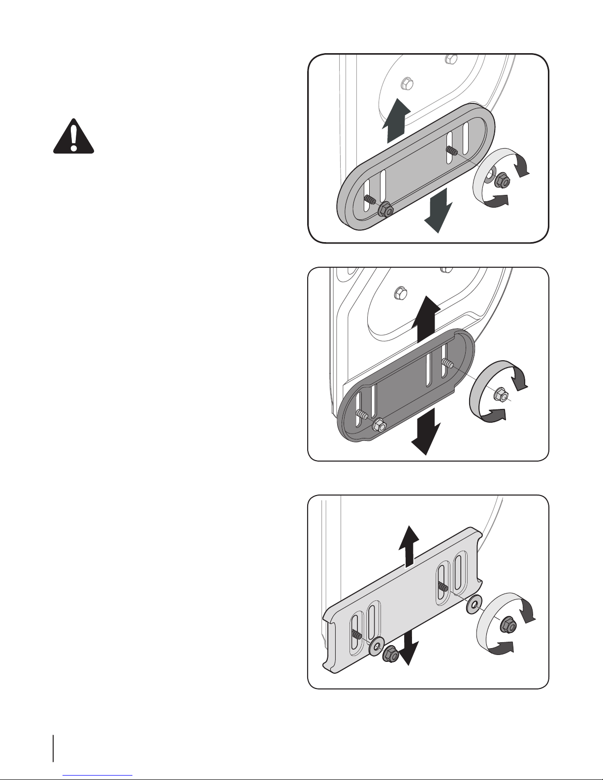
Skid Shoes
The snow thrower skid shoes are adjusted at the factory. Adjust
them downward, if desired, prior to operating the snow thrower.
CAUTION: It is not recommended that you operate this snow
thrower on gravel as it can easily pick up and throw loose gravel,
causing personal injury or damage to the snow thrower and
surrounding property.
• For close snow removal on a smooth surface, raise skid
shoes higher on the auger housing.
• Use a middle or lower position when the area to be cleared
is uneven, such as a gravel driveway.
NOTE: If you choose to operate the snow thrower on a gravel
surface, keep the skid shoes in position for maximum clearance
between the ground and the shave plate.
To adjust the skid shoes:
1. Loosen the four hex nuts (two on each side) and carriage
bolts. Move skid shoes to desired position. See Fig. 3-13,
Fig. 3-14 or Fig. 3-15.
2. Make certain the entire bottom surface of skid shoe is
against the ground to avoid uneven wear on the skid shoes.
3. Retighten nuts and bolts securely.
NOTE: Some models are equipped with reversible skid shoes
and may be turned over to increase their lifespan.
Fi g. 3-13
Fi g. 3-14
10 Section 3— ASSe mbly & Set-Up
Fi g. 3-15
Page 11
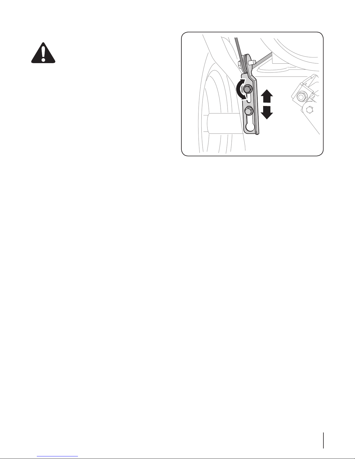
Auger Control Test
WARNING : Prior to operating your snow thrower,
carefully read and follow all instructions below.
Perform all adjustments to verify your unit is
operating safely and properly.
Perform the following test before operating your snow thrower
for the first time and at the start of each winter.
Check the adjustment of the auger control as follows:
1. When the auger control is released and in the disengaged
“up” position, the cable should have very little slack. It
should NOT be tight.
2. In a well-ventilated area, start the snow thrower engine as
instructed in the separate engine manual.
3. While standing in the operator’s position (behind the snow
thrower), engage the auger.
4. Allow the auger to remain engaged for approximately ten
(10) seconds before releasing the auger control. Repeat this
several times.
5. With the auger control in the disengaged “up” position,
walk to the front of the machine.
6. Confirm that the auger has completely stopped rotating
and shows NO signs of motion. If the auger shows ANY
signs of rotating, immediately return to the operator’s
position and shut off the engine. Wait for ALL moving parts
to stop before re-adjusting the auger control.
7. To readjust the control cable, loosen the upper hex screw
on the auger cable bracket. Position the bracket upward
to provide more slack (or downward to increase cable
tension). See Fig. 3-16.
8. Position the bracket upward to provide more slack (or
downward to increase cable tension).
9. Retighten the upper hex screw.
10. Repeat Auger Control Test to verify proper adjustment has
been achieved.
Fi g. 3-16
11Section 3 — ASSemb ly & Set-Up
Page 12
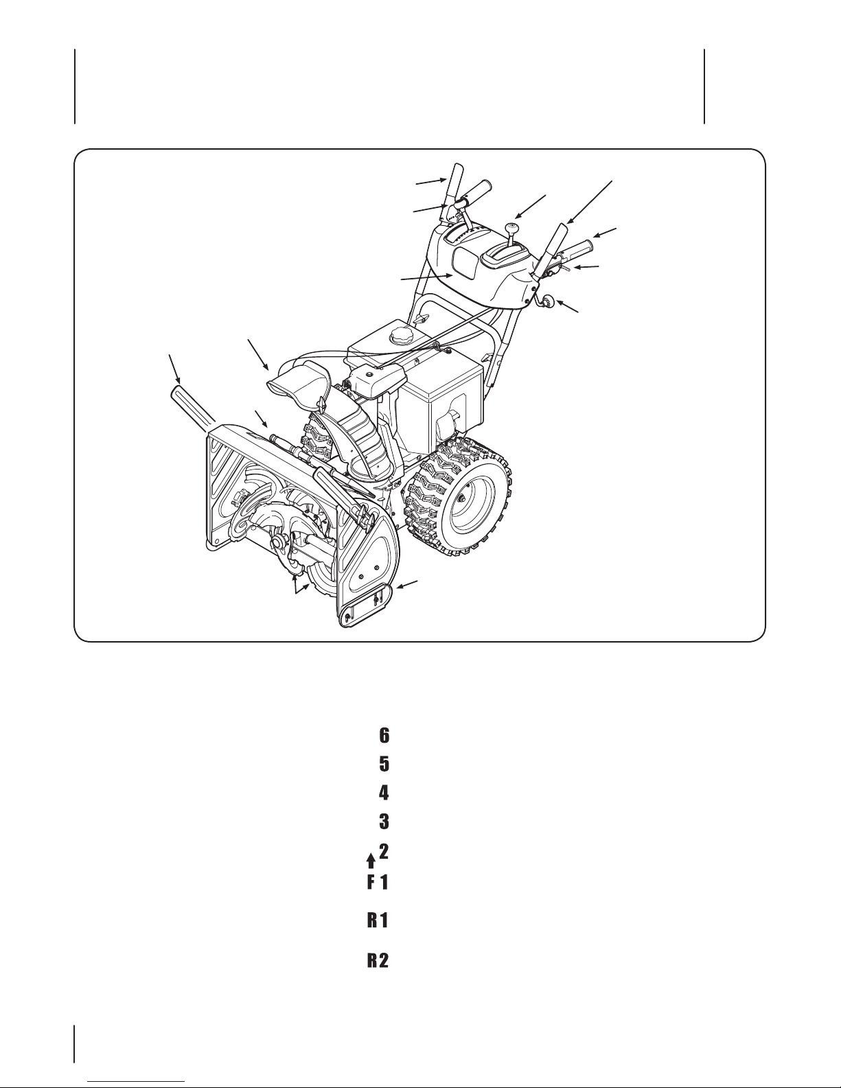
Controls and Features
4
Drift Cutters
(if equipped)
Chute Assembly
Clean Out
Tool
Drive Control
Shift Lever
Headlight
2 Way
Chute Control
Auger Control
Heated Grips
(if equipped)
Steering Trigger Control
(if equipped)
Chute Directional Control
Augers
Snow thrower controls and features are described below and
illustrated in Figure 4-1.
Shift Lever
The shift lever is located in the right side of the
handle panel and is used to determine ground
speed and direction of travel.
Forward
There are six forward (F) speeds. Position one (1) is
the slowest and position six (6) is the fastest.
Reverse
There are two reverse (R) speeds. One (1) is the
slower and two (2) is the faster.
Skid Shoe
Figure 4-1
Skid Shoes
Position the skid shoes based on surface conditions. Adjust
upward for hard-packed snow. Adjust downward when
operating on gravel or crushed rock surfaces. See Set-Up &
Assembly section.
Augers
When engaged, the augers rotate and draw snow into the auger
housing.
Chute Assembly
Snow drawn into the auger housing is discharged out the chute
assembly.
Headlight
The headlight is located on the handle panel and is automatically
turned on when the engine is started.
12
Page 13
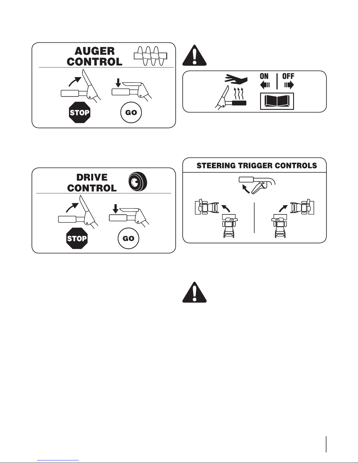
Auger Control
The auger control is located on the left handle. Squeeze the
control grip against the handle to engage the augers and start
snow throwing action. Release to stop.
Drive Control / Auger Clutch Lock
Heated Grips (If so Equipped)
CAUTION: It is recommended that you wear
gloves when using the heated grip. If the heated
grip become too hot, turn it off.
To activate the heated grips, move the switch found on the rear
of the dash panel into the ON position. To turn off the heated
grips, move the switch found on the rear of the dash panel to the
OFF position.
Steering Trigger Controls
The drive control is located on the right handle. Squeeze the
control grip against the handle to engage the wheel drive.
Release to stop.
The drive control also locks the auger control so that you can
operate the chute directional control without interrupting
the snow throwing process. If the auger control is engaged
simultaneously with the drive control, the operator can release
the auger control (on the left handle) and the augers will remain
engaged. Release both controls to stop the augers and wheel
drive.
Note: Always release the drive control before changing speeds.
Failure to do so will result in increased wear on your machine’s
drive system.
The left and right wheel steering trigger controls are located on
the underside of the handles.
• Squeeze the right control to turn right.
• Squeeze the left control to turn left.
CAUTION: Operate the snow thrower in open
areas until you are familiar with these controls.
13Section 4 — controlS an d FeatureS
Page 14
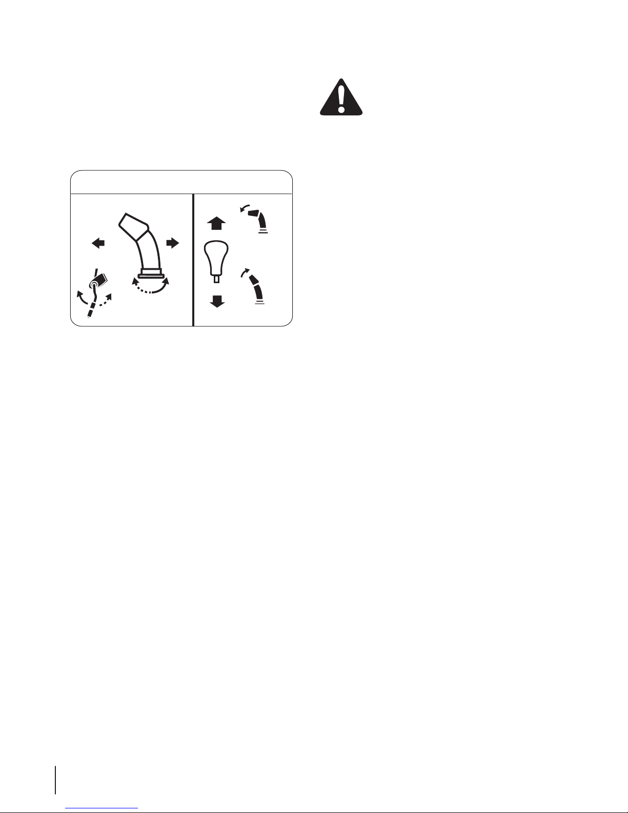
Two-Way Chute Control™ (if equipped)
CHUTE DIRECTIONAL CONTROL
DISCHARGE
LEFT
DISCHARGE
RIGHT
CHUTE TILT
DOWN
CHUTE TILT
UP
This two-way control lever is meant to control the distance of
snow discharge from the chute. Tilt the lever forward or rearward
to adjust the distance snow will be thrown.
Chute Directional Control (if equipped)
The chute directional control can be turned clockwise or
counterclockwise to change the direction in which snow is
thrown.
Drift Cutters (If equipped)
The drift cutters are designed for use in deep snow. Their use
is optional for normal snow conditions. Maneuver the snow
thrower so that the cutters penetrate a high standing snow drift
to assist snow falling into the augers for throwing.
Chute Clean-Out Tool
WARNING! Never use your hands to clear a
clogged chute assembly. Shut off engine and remain
behind handles until all moving parts have stopped
before unclogging.
The chute clean-out tool is conveniently fastened to the rear of
the auger housing with a mounting clip. Should snow and ice
become lodged in the chute assembly during operation, proceed
as follows to safely clean the chute assembly and chute opening:
1. Release both the Auger Control and the Drive Control.
2. Stop the engine. Refer to the Engine Operator’s Manual.
Remove the key.
3. Remove the clean-out tool from the clip which secures it to
the rear of the auger housing.
4. Use the shovel-shaped end of the clean-out tool to
dislodge and scoop any snow and ice which has formed in
and near the chute assembly.
5. Refasten the clean-out tool to the mounting clip on the
rear of the auger housing, reinsert the key and start the
snow thrower’s engine.
While standing in the operator’s position (behind the snow
thrower), engage the auger control for a few seconds to clear any
remaining snow and ice from the chute assembly.
14 Sectio n 4 — contro lS and FeatureS
Page 15
Operation
5
Starting and Stopping the Engine
Refer to the Engine Operator’s Manual packed with your snow
thrower for instructions on starting and stopping the engine.
To Engage Drive
1. With the throttle control in the Fast (rabbit) position, move
shift lever into one of the six forward (F) positions or two
reverse (R) positions. Select a speed appropriate for the
snow conditions and a pace you’re comfortable with.
2. Squeeze the drive control against the handle the snow
thrower will move. Release it and drive motion will stop.
To Engage Augers
To engage the augers and start throwing snow, squeeze the
auger control against the left handle. Release to stop the augers.
To Steer
With the drive control engaged, squeeze the right steering
trigger control to turn right. Squeeze the left steering trigger
control to turn left.
CAUTION: Operate the snow thrower in open
areas and at slow speeds until you are familiar with
the drive control and comfortable operating the
steering controls.
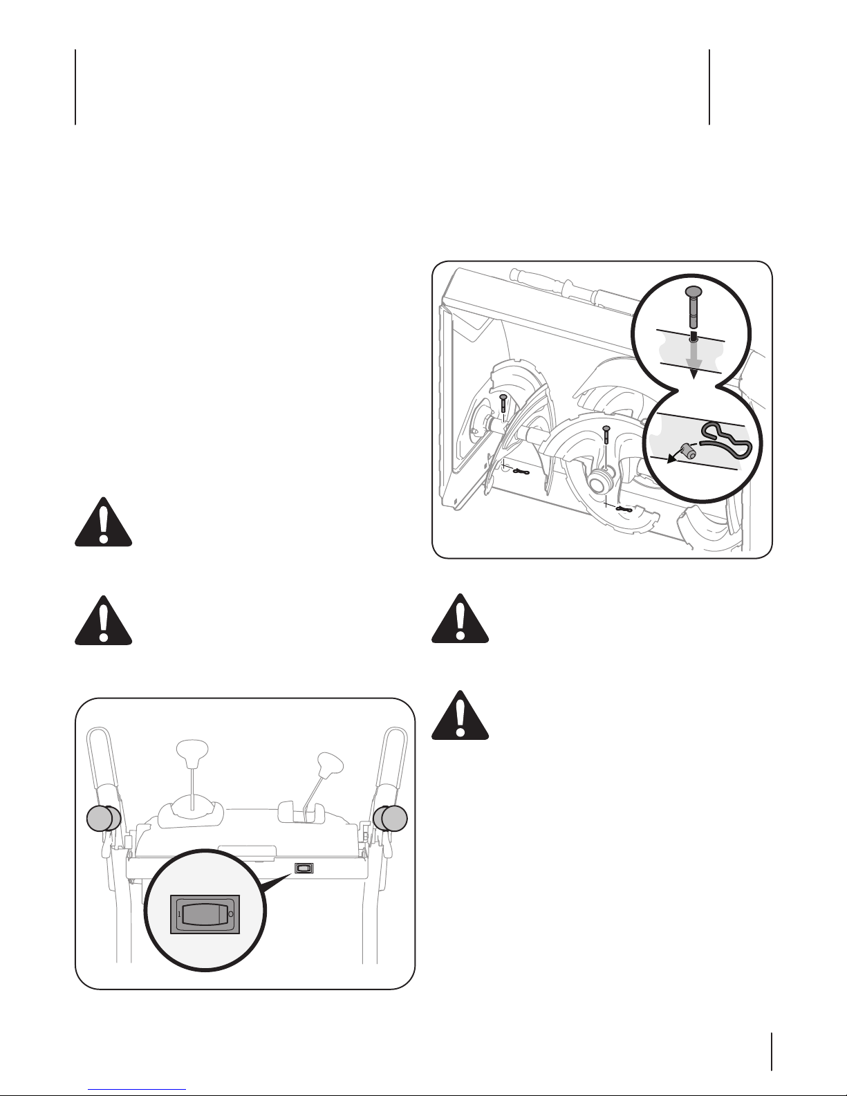
Replacing Shear Pins
The augers are secured to the spiral shaft with shear pins and
cotter pins. If the auger should strike a foreign object or ice jam,
the snow thrower is designed so that the pins may shear. If the
augers will not turn, check to see if the pins have sheared. See
Figure 5-2.
Engage Heated Grips (If so Equipped)
CAUTION: It is recommended that you wear
gloves when using the heated grip. If the heated
grip become too hot, turn it off.
To activate the heated grips, move the switch found on the rear
of the dash panel into the ON position. See Figure 5-1.
Figure 5-2
CAUTION: NEVER replace the auger shear pins
with anything other than OEM Part No.738-04124A
replacement shear pins. Any damage to the auger
gearbox or other components as a result of failing to
do so will NOT be covered by your snow thrower’s
warranty.
WARNING! Always turn off the snow thrower’s
engine and remove the key prior to replacing shear
pins.
Figure 5-1
15
Page 16

Maintenance & Adjustments
6
Maintenance
Engine
Refer to the Engine Operator’s Manual.
Tire Pressure
Refer to Assembly and Set-up section for information regarding
tire pressure.
Shave Plate and Skid Shoes
The shave plate and skid shoes on the bottom of the snow
thrower are subject to wear. They should be checked periodically
and replaced when necessary.
NOTE: Some units are equipped with reversible skid shoes and
may be turned over to increase their lifespan.
To remove skid shoes:
1. Remove the four carriage bolts and hex flange nuts which
secure them to the snow thrower.
2. Reassemble new skid shoes with the four carriage bolts
(two on each side) and hex flange nuts. Refer to Fig. 6-1.
Lubrication
Wheels
At least once a season, remove both wheels. Clean and coat the
axles with a multipurpose automotive grease before reinstalling
wheels.
Auger Shaft
At least once a season, remove the shear pins from the auger
shafts. Spray lubricant inside the shafts and around the spacers
and the flange bearings/bushings found at either end of the
shafts. See Figure 6-2.
Figure 6-1
To remove shave plate:
1. Remove the carriage bolts and hex nuts which attach it to
the auger housing.
2. Reassemble new shave plate, making sure heads of carriage
bolts are to the inside of housing. Tighten securely.
16
Figure 6-2
Gear Shaft
The gear (hex) shaft should be lubricated at least once a season
or after every twenty-five (25) hours of operation.
1. Allow the engine to run until it is out of fuel.
2. Carefully pivot the snow thrower up and forward so that it
rests on the auger housing.
3. Remove the frame cover from the underside of the snow
thrower by removing the self-tapping screws which secure
it. Refer to Figure 6-3.
Page 17

Figure 6-3
4. Apply a light coating of Regular Grade Anti-Seize to the hex
shaft. See Figure 6-4.
NOTE: When lubricating the hex shaft, be careful not to get
any anti-seize on the aluminum drive plate or the rubber
friction wheel. Doing so will hinder the snow thrower’s
drive system. Wipe off any excess.
Adjustments
Shift Cable
If the full range of speeds (forward and reverse) cannot be
achieved, adjust the shift cable as follows:
1. Place the shift lever in the fastest forward speed position.
2. Loosen the hex nut on the shift cable index bracket. See
Figure 6-5.
Figure 6-4
Figure 6-5
3. Pivot the bracket downward to take up slack in the cable.
4. Retighten the hex nut.
5. If further adjustment is necessary move the shift cable to
one of the alternate holes in the shift cable index bracket.
Auger Control
Refer to the Assembly and Set-up section for instructions on
adjusting the auger control cable.
Skid Shoes
Refer to the Assembly and Set-up section for instructions on
adjusting the skid shoes.
17Section 6 — Maintenan ce & adjuStMentS
Page 18

Drive Control
When the drive control is released and in the disengaged “up”
position, the cable should have very little slack. It should NOT be
tight.
NOTE: If excessive slack is present in the drive cable or if the snow
thrower’s drive is disengaging intermittently during operation,
the cable may be in need of adjustment.
Check the adjustment of the drive control as follows:
1. With the drive control released, push the snow thrower
gently forward. The unit should roll freely.
2. Engage the drive control and gently attempt to push the
snow thrower forward. The wheels should not turn. The
unit should not roll freely.
3. With the drive control released, move the shift lever back
and forth between the R2 position and the F6 position
several times. There should be no resistance in the shift
lever.
If any of the above tests failed, the drive cable is in need of
adjustment. Proceed as follows:
1. Shut off the engine as instructed in the separate engine
manual.
2. Loosen the lower hex screw on the drive cable bracket. See
Figure 6-6.
Chute Assembly (Overhead Chute Control)
If the chute fails to remain stationary during operation, the
pre-load of the chute can be adjusted by tightening the hex nut
found on the front of the chute control assembly.
To increase the preload, tighten the hex nut clockwise in ¼ turn
intervals. See Figure 6-7.
Figure 6-6
3. Position the bracket upward to provide more slack (or
downward to increase cable tension).
4. Retighten the upper hex screw.
5. Check the adjustment of the drive control as described
earlier to verify proper adjustment has been achieved.
Figure 6-7
If the chute directional control is difficult to crank, decrease the
preload by loosening the hex nut counterclockwise in ¼ turn
intervals.
Off-Season Storage
If the snow thrower will not be used for 30 days or longer, follow
the storage instructions below.
1. Lubricate the machine as instructed earlier in this section.
2. Store in a clean, dry area.
3. If storing the snow thrower in an unventilated area,
rustproof the machine using a light oil or silicone to coat
the snow thrower.
4. Clean the exterior of the engine and the snow thrower.
IMPORTANT: When storing unit or when it is not being serviced,
it is to remain in the operating position with both wheel and
auger housing on the ground.
NOTE: Refer to the Engine Operator’s Manual for information on
storing your engine.
18 Section 6 — Mainte nance & adjuStMentS
Page 19

Service
7
Belt Replacement
Auger Belt
To remove and replace your snow thrower’s auger belt, proceed
as follows:
1. Allow the engine to run until it is out of fuel. Do not
attempt to pour fuel from the engine.
2. Remove the plastic belt cover on the front of the engine by
removing the two self-tapping screws. See Figure 7-1.
4. Roll the auger belt off the engine pulley. See Figure 7-3.
Figure 7-3
5. Carefully pivot the snow thrower up and forward so that it
rests on the auger housing.
6. Remove the frame cover from the underside of the snow
thrower by removing the self-tapping screws which secure
it. See Figure 7-4.
Figure 7-1
3. Remove the wire belt keeper by removing the two hex
bolts and flat washers. See Figure 7-12.
Figure 7-2
Figure 7-4
19
Page 20

7. Loosen and remove the shoulder bolt which acts as a belt
keeper. See Figure 7-5.
Figure 7-5
7. Remove the belt from around the auger pulley, and slip the
belt between the support bracket and the auger pulley.
See Figure 7-6.
NOTE: Engaging the auger control will ease removal and
reinstallation of the belt.
Drive Belt
NOTE: Special tools are required and several components must
be removed in order to replace the snow thrower’s drive belt. See
your authorized service dealer to have the drive belt replaced or
phone Customer Support as instructed on page 2 for assistance.
Friction Wheel Inspection
If the snow thrower fails to drive with the drive control engaged,
and performing the drive control cable adjustment fails to
correct the problem, the friction wheel may need to be replaced.
NOTE: Special tools are required and several components must
be removed in order to replace the snow thrower’s friction wheel
rubber. See your authorized service dealer to have the friction
wheel rubber replaced or phone Customer Support as instructed
on page 2 for assistance.
To inspect the friction wheel, proceed as follows:
1. Allow the engine to run until it is out of fuel. Do not
attempt to pour fuel from the engine.
2. Carefully pivot the snow thrower up and forward so that it
rests on the auger housing.
3. Remove the frame cover from the underside of the snow
thrower by removing four self-tapping screws which secure
it. See Figure 7-4.
4. Examine the friction wheel for signs of wear or cracking.
Friction Wheel
Figure 7-6
8. Replace the auger belt by following instructions in reverse
order.
NOTE: Do not forget to reinstall the shoulder bolt and
reconnect the spring to the frame after installing a
replacement auger belt.
9. After replacing the auger belt, perform the Auger Control
test on page 11 of the Assembly and Set-Up section.
20 Section 7— Service
Page 21

Replacement Parts
Component Part Number and Description
9
954-04195A Auger Drive Belt
954-04201A Wheel Drive Belt
684-04153C Friction Wheel Assembly
935-04054 Friction Wheel Rubber
925-1629 Lamp, 12V
738-04124A Shear Pin, 1.50
714-04040 Bow-tie Cotter Pin
790-00091 Slide Shoe, Deluxe (Steel)
731-06931 Skid Shoe, Deluxe (Blue polymer)
931-2643 Chute Clean-out Tool
790-00120 Shave Plate (3X 24)
790-00121 Shave Plate (3X 26)
790-00118 Shave Plate (3X 28)
951-10630 Key
951-10292 Spark Plug
NOTE: Download a complete Parts Manual, refer to customer support on page 2. Be sure to have your model number and serial
number ready. Refer to page 2 for more information regarding locating your model and serial numbers.
21
Page 22

Troubleshooting
Problem Cause Remedy
8
Engine fails to start 1. Choke not in CHOKE position.
2. Spark plug wire disconnected.
3. Fuel tank empty or stale fuel.
4. Engine not primed.
5. Faulty spark plug.
6. Key not in ignition on engine.
Engine running erratically/
inconsistent RPM (hunting or
surging)
Engine overheats 1. Carburetor not adjusted properly. 1. Contact an authorized Service Center.
Excessive vibration 1. Loose parts or damaged auger. 1. Stop engine immediately and disconnect spark plug wire.
Loss of power 1. Spark plug wire loose.
Unit fails to propel itself 1. Drive control cable in need of
1. Engine running on CHOKE.
2. Stale fuel.
3. Water or dirt in fuel system.
4. Carburetor out of adjustment.
5. Engine over-governed
2. Gas cap vent hole plugged.
adjustment.
2. Drive belt loose or damaged.
3. Friction wheel worn.
1. Move choke to CHOKE position.
2. Connect wire to spark plug.
3. Fill tank with clean, fresh gasoline.
4. Prime engine as instructed in the Operation section.
5. Clean, adjust gap, or replace.
6. Insert key fully into the switch.
1. Move choke lever to RUN position.
2. Fill tank with clean, fresh gasoline.
3. Drain fuel tank. Refill with fresh fuel.
4. Contact an authorized Service Center.
5. Contact an authorized Service Center.
Tighten all bolts and nuts. If vibration continues, have unit
serviced by an authorized Service Center.
1. Connect and tighten spark plug wire.
2. Remove ice and snow from gas cap. Be certain vent hole
is clear.
1. Adjust drive control cable. Refer to Maintenance &
Adjustments section.
2. Replace drive belt. Refer to Service section
3. Replace friction wheel. Refer to Service section.
Unit fails to discharge snow 1. Chute assembly clogged.
Engine fails to start 1. Extension cord not connected (when
Chute fails to easily rotate 180
degrees
Chute does not stay stationary
while throwing snow using an
overhead chute control.
2. Foreign object lodged in auger.
3. Auger control cable in need of
adjustment.
4. Auger belt loose or damaged.
5. Shear pin(s) sheared.
using electric start button, on models so
equipped)
1. Chute assembled incorrectly. 1. Unassemble chute control and reassemble as directed in
1. Insufficient tension applied to chute
control.
22
1. Stop engine immediately and disconnect spark plug wire.
Clean chute assembly and inside of auger housing with
clean-out tool or a stick.
2. Stop engine immediately and disconnect spark plug wire.
Remove object from auger with clean-out tool or a stick.
3. Refer to Auger Control Test.
4. Refer to Maintenance & Adjustments section.
5. Replace with new shear pin(s).
1. Connect one end of the extension cord to the electric
starter outlet and the other end to a three-prong 120-volt,
grounded, AC outlet.
the Assembly & Set-up section.
2. Refer to the Maintenance & Adjustments section to adjust
chute preload.
Page 23

THREE YEAR LIMITED WARRANTY
The limited warranty set forth below is given by MTD Products Limited with respect to new merchandise purchased and used in Canada and/
or its territories and possessions (either entity respectively, “MTD”).
MTD warrants this product (excluding its normal wear parts as described below) against defects in material and workmanship for a period
of three (3) years commencing on the date of original purchase and will, at its option, repair or replace, free of charge, any part found to be
defective in materials or workmanship. This limited warranty shall only apply if this product has been operated and maintained in accordance
with the Operator’s Manual furnished with the product, and has not been subject to misuse, abuse, commercial use, neglect, accident,
improper maintenance, alteration, vandalism, theft, fire, water, or damage because of other peril or natural disaster. Damage resulting from
the installation or use of any part, accessory or attachment not approved by MTD for use with the product(s) covered by this manual will void
your warranty as to any resulting damage.
Normal wear parts are warranted to be free from defects in material and workmanship for a period of thirty (30) days from the date of purchase. Normal wear parts include, but are not limited to items such as: batteries, belts, blades, blade adapters, grass bags, rider deck wheels,
seats, snow thrower skid shoes, friction wheels, shave plates, auger spiral rubber, tires, engine oil, air filters and spark plugs.
Lifetime Warranty on Polymer Snow Discharge Chute: If your product is a snow thrower equipped with a polymer snow discharge chute
(the “Snow Chute”), and the Snow Chute fails, breaks, or malfunctions, the manufacturer will repair or replace the Snow Chute at no cost as
long as it is still owned by the original purchaser (or the original person for whom this product was purchased as a gift). Control mechanisms
attached to the Snow Chute, such as cables and control linkages, are covered under the other terms of this limited warranty, but are not
covered by this paragraph (or beyond the normal applicable warranty period). Except as specifically modified by this paragraph, all of the
other terms, limitations, and conditions set forth in this document shall continue to apply to the Snow Chute.
HOW TO OBTAIN SERVICE: Warranty service is available, WITH PROOF OF PURCHASE, through your local authorized service dealer. To locate
the dealer in your area;
In the U.S.A.: Check your Yellow Pages, or contact MTD LLC at P.O. Box 361131, Cleveland, Ohio 44136-0019, or call 1-800 -800-7310 or 1-330220-4683 or log on to our Web site at www.mtdproducts.com.
In Canada: Contact MTD Products Limited, Kitchener, ON N2G 4J1, or call 1-800-668-1238 or log on to our Web site at www.mtdcanada.com.
This limited warranty does not provide coverage in the following cases:
a. The engine or component parts thereof. These items may carry a separate manufacturer’s warranty. Refer to applicable manufac-
turer’s warranty for terms and conditions. The Powermore engine is not excluded under this agreement.
b. Log splitter pumps, valves, and cylinders have a separate one-year warranty.
c. Routine maintenance items such as lubricants, filters, blade sharpening, tune-ups, brake adjustments, clutch adjustments, deck
adjustments, and normal deterioration of the exterior finish due to use or exposure.
d. Service completed by someone other than an authorized service dealer.
e. MTD does not extend any warranty for products sold or exported outside of Canada, including possessions and territories.
f. Replacement parts that are not genuine MTD parts.
g. Transportation charges and service calls.
h. If Products are used commercially. (MTD may separately offer Limited Commercial Warranties on certain select products. Ask your
dealer or retailer for details or contact MTD Service for more information.)
No implied warranty, including any implied warranty of merchantability of fitness for a particular purpose, applies after the applicable period of express written warranty above as to the parts as identified. No other express warranty, whether written or oral,
except as mentioned above, given by any person or entity, including a dealer or retailer, with respect to any product, shall bind
MTD. During the period of the warranty, the exclusive remedy is repair or replacement of the product as set forth above.
The provisions as set forth in this warranty provide the sole and exclusive remedy arising from the sale. MTD shall not be liable for
incidental or consequential loss or damage including, without limitation, expenses incurred for substitute or replacement lawn
care services or for rental expenses to temporarily replace a warranted product.
Some jurisdictions do not allow the exclusion or limitation of incidental or consequential damages, or limitations on how long an implied
warranty lasts, so the above exclusions or limitations may not apply to you.
In no event shall recovery of any kind be greater than the amount of the purchase price of the product sold. Alteration of safety features of
the product shall void this warranty. You assume the risk and liability for loss, damage, or injury to you and your property and/or to others
and their property arising out of the misuse or inability to use the product.
This limited warranty shall not extend to anyone other than the original purchaser or to the person for whom it was purchased as a gift.
HOW LOCAL LAWS RELATE TO THIS WARRANTY: This limited warranty gives you specific legal rights, and you may also have other rights
that vary in different jurisdictions.
IMPORTANT: Owner must present Original Proof of Purchase to obtain warranty coverage.
MTD LLC, P.O. BOX 361131 CLEVELAND, OHIO 44136-0019; Phone: 1-800-800-7310, 1-330-220-4683
MTD Products Ltd., P. O. BOX 1386, KITCHENER, ON N2G 4J1; Phone: 1-800-668-1238
05.10.11
23
Page 24

Notes
24
Page 25

24
Notes
Page 26

23
05.10.11
MTD Products Ltd., C.P. 1386, Kitchener, Ontario N2G 4J1; téléphone: 1-800-668-1238
MTD LLC, P.O. Box 361131, Cleveland, Ohio 44136-0019; téléphone: 1-800-800-7310, 1-330-220-4683
IMPORTANT : Le propriétaire doit présenter le reçu original pour faire honorer la garantie.
droits qui varient selon les juridictions.
LES LOIS LOCALES ET CETTE GARANTIE : Cette garantie limitée vous accorde des droits juridiques spécifiques et vous pouvez bénéficier d’autres
Cette garantie limitée n’est offerte qu’à l’acheteur initial ou à la personne à laquelle le produit a été offert en cadeau.
perte, de dommage matériel ou de blessure résultant de l’utilisation incorrecte du produit ou de l’incapacité de l’employer.
tion des caractéristiques de sécurité rendra la garantie nulle et non avenue. L’utilisateur assume tout risque et toute responsabilité en cas de
Le remboursement ou remplacement quel qu’il soit ne sera en aucun cas supérieur au montant du prix d’achat du produit vendu. Tout e mo dif ica -
tacite. Par conséquent, les exclusions ci-dessus peuvent ne pas s’appliquer dans votre situation.
Certaines juridictions ne permettent pas l’inclusion ou la restriction des dommages accessoires ou immatériels ou une limite à la durée de la garantie
d’entretien des pelouses ou les frais de location pour remplacer temporairement un article sous garantie.
perte ou tout dommage accessoire ou immatériel comprenant, sans s’y limiter, les frais de remplacement ou de substitution des services
Les stipulations énoncées dans cette garantie offrent le seul recours à la suite de la vente. MTD ne peut être tenue responsable pour toute
à la disposition du client.
produit, n’engage MTD. Pendant la période de garantie, la réparation ou le remplacement du produit ci-dessus constitue le recours exclusif
ou écrite, à l’exception des stipulations ci-dessus, offerte par toute personne ou entité (y compris un concessionnaire/revendeur), pour tout
pièces identifiées ci-dessus après la période de vigueur de la garantie écrite expresse. Aucune autre garantie expresse, qu’elle soit verbale
Aucune garantie tacite, y compris toute garantie tacite de qualité marchande ou d’adaptabilité dans un but particulier, ne s’applique aux
vente de MTD.)
commercial. Renseignez-vous auprès du concessionnaire ou détaillant pour plus de détails ou adressez-vous directement au service après-
h. Les produits utilisés dans un but commercial. (Certains produits peuvent être accompagnés d’une garantie limitée MTD séparée pour usage
g. Les frais de transport des machines et de déplacement des techniciens.
f. Les pièces de rechange si elles ne sont pas des pièces MTD authentiques.
e. MTD ne garantit pas les produits vendus ou exportés du Canada, de ses possessions et territoires.
d. L’entretien ou les réparations effectués par quiconque autre qu’une station technique agréée.
plateau de coupe et la détérioration normale de la finition du fait de l’utilisation de la machine ou de son exposition aux intempéries.
c. Les articles d’entretien courant tels que les lubrifiants, filtres, aiguisages de lame et révisions, les réglages de frein, de l’embrayage ou du
b. Les pompes, soupapes et pistons des fendeuses à bois sont couverts par une garantie séparée d’un an.
quant aux conditions. Le moteur Powermore à soupapes en tête n’est pas exclus aux termes de cette garantie.
a. Le moteur ou ses composants. Ces articles peuvent être couverts par une garantie séparée du fabricant. Consultez la garantie du fabricant
Cette garantie limitée ne couvre pas:
mtdcanada.com
Au Canada : Adressez-vous à MTD Products Limited, Kitchener, Ontario, N2G 4J1 ou appelez le 1-800-668-1238 ou visitez notre site web au www.
ou le 1-330-220-4683. Vous pouvez aussi visiter notre site web au www.mtdproducts.com
Aux États-Unis : Consultez les Pages Jaunes ou adressez-vous à MTD LLC, P.O. Box 361131, Cleveland, Ohio 44136-0019 ou appelez le 1-800-800-7310
technique agréée ou un concessionnaire dans votre région :
POUR FAIRE HONORER LA GARANTIE : Présentez UNE PREUVE D’ACHAT à la station technique agréée de votre localité. Pour localiser une station
tions énoncées dans ce document continueront à s’appliquer à la goulotte, à moins de modifications expresses mentionnées dans ce paragraphe.
Elle ne sont toutefois pas couvertes par ce paragraphe (ni au-delà de la période normale de la garantie). Toutes les autres clauses, restrictions et condicommandes installées sur la goulotte, c’est-à-dire les câbles et timoneries de commande, sont couvertes par d’autres clauses de cette garantie limitée.
ou à remplacer cette goulotte gratuitement si elle est toujours la propriété de l’acheteur initial (ou si le propriétaire initial l’a reçue en cadeau). Les
en polymère (la “goulotte”) et que celle-ci présente une défaillance, se brise ou ne fonctionne pas correctement, le fabricant s’engage à réparer
Garantie limitée de la goulotte d’éjection en polymère : Si le matériel en question est une souffleuse à neige équipée d’une goulotte d’éjection
tarière et pneus l’huile à moteur, les filtres à air et bougies.
à herbe, roues du plateau de coupe des tondeuses à siège, sièges, patins de souffleuses, roues de frottement, lames de raclage, le caoutchouc de la
de la date d’achat. Les pièces et composants à usure normale comprennent, sans s’y limiter, les batteries, courroies, lames, adaptateurs de lame, sacs
Les pièces ou composants à usure normale sont garantis exempts de tout vice de matière et de fabrication pour une période de 30 jours à compter
homologué par MTD, rendront la garantie nulle et non avenue.
ou l’utilisation d’une pièce, d’un accessoire ou d’un équipement annexe, dont l’emploi avec le produit faisant l’objet de la notice d’utilisation n’est pas
isme, d’un vol, d’un incendie, d’une inondation ou de tout autre dégât causé par tout incident ou désastre naturel. Les dégâts causés par l’installation
abusif, d’une utilisation à des fins commerciales, d’une négligence, d’un accident, d’un entretien incorrect, d’une modification, d’un acte de vandalconformément aux instructions de la notice d’utilisation qui l’accompagne. De plus, le produit ne doit pas avoir fait l’objet d’un emploi incorrect ou
s’avère défectueuse en raison d’un vice de matière ou de fabrication. Cette garantie limitée n’est applicable que si ce produit a été utilisé et entretenu
pour une durée de trois (3) ans à compter de la date de l’achat initial et s’engage à réparer ou à remplacer, gratuitement et à son choix, toute pièce qui
« MTD » garantit que ce produit (à l’exception des pièces à usure normale énumérées ci-dessous)est exempt de tout vice de matière et de fabrication
ou ses territoires (l’une ou l’autre entité respectivement appelée « MTD »).
La garantie limitée qui est énoncée ci-dessous est offerte par MTD Products Limited, pour toutes les marchandises achetées et utilisées au Canada et/
GARANTIE LIMITÉE DE TROIS ANS
Page 27

951-10630 Bougie
951-10630 Clé
790-00550 Lame plate (3X 30 HD)
790-00549 Lame plate (3X 28 HD)
790-00525 Lame plate (3X 26 HD)
790-006525 Lame plate (3X 24 HD)
22
machine.
vente» à la page 2. Voir les renseignements qui se trouvent à la page 2 pour localiser les numéros de modèle et de série de votre
REMARQUE: Vous pouvez télécharger un livret contenant la liste complète des pièces détachées adressez-vous au «Service après-
931-2643 Outil de dégagement de la goulotte
731-06931 Patin, de luxe (bleu Polymer)
790-00091 Patin, de luxe (acier)
714-04040 Goupille fendue
738-04124A Goupille de cisaillement, 1,50
925-1629 Phare, 12V
935-04054 Roue de friction en caoutchouc
684-04153C Roue de friction
954-04201A Courroie de transmission
954-04195A Courroie de la tarière
9
Component No. de pièce et description
Pièces de rechange
Page 28

21
goulotte.
de direction de la
une commande
neige utilisant
tout en jetant la
de la goulot te, consultez le chapitre « Entretien et réglages ».
1. Pour régler la tension de la sur la manivelle de commande
insuffisante
1. La tension appliquée à la commande de la goulotte est
pas stationnaire
La goulotte ne reste
».
comme instruit dans le chapitre « Assemblage et montage
grounded, AC outlet.
starter outlet and the other end to a three-prong 120-volt,
1. Connect one end of the extension cord to the electric
5. Remplacez la goupille de cisaillement.
4. Voir le Régime d’entretien.
3. Voir Test de commande de la tarière.
l’outil de dégagement de la goulotte ou un bâton.
la bougie. Dégagez le corps étranger de la tarière avec
2. Arrêter immédiatement le moteur et débranchez le fil de
du logement de la tarière.
la bougie. Nettoyez la goulotte d’évacuation et l’intérieur
1. Arrêtez immédiatement le moteur et débranchez le fil de
3. Remplacez la roue de frottement.
2. Remplacez la courroie d’entraînement.
1. Réglez le câble d’entraînement. Voir le Réglages.
la propreté d’aération.
2. Dégagez la glace et la neige du chapeau. Assurez-vous de
1. Branchez et serrez le fil de la bougie.
station technique agréée.
vibrations persistent, faites vérifier la machine par une
de la bougie. Serrez tous les boulons et écrous. Si les
1. Arrêtez immédiatement le moteur et débranchez le fil
1. La goulotte n’est pas assemble correctement 1. Démontez la commande de la goulotte et remontez-la
button, on models so equipped)
5. Goupille de cisaillement est cisaillé.
du jeu.
4. Courroie d’entraînement de la tarière abîmée ou ayant
3. Câble d’entraînement de la tarière mal réglé.
2. Présence de corps étranger dans la tarière.
1. Goulotte d’évacuation bouchée.
3. La roue de frottement est usée.
2. Co urroie d’entraînement abîmée ou ayant du jeu.
1. Câble d’entraînement mal réglé.
2. Chapeau d’échappement d’aération bouché.
endommagée.
degrés
pas facilement 180
La goulotte ne tourne
Engine fails to start 1. Extension cord not connected (when using electric start
pas la neige
La souffleuse n’évacue
pas
La souffleuse n’avance
Perte de puissance 1. Fil de la bougie desserré.
Vibration excessives 1. Pièces desserrées ou vis sans fin
8
Moteur surchauffe 1. Carburateur est mal réglé. 1. Adressez-vous à une station technique.
5. Adressez-vous à une station technique.
4. Adressez-vous à une station technique.
et fraîche
3. Videz le réservoir. Faites le plein avec une essence propre
2. Faites le plein avec une essence propre.
1. Enlever de la position “volet de dépar t”.
6. Mettez la clé.
5. Nettoyez, réglez l’écartement ou remplacez la bougie.
4. Consultez le chapitre “Utilisation de la Souffleuse”.
3. Faite le plein avec une essence propre et fraîche.
2. Branchez le fil de la bougie.
1. Selectioner la position “volet de départ”.
5. Régulateur déréglé .
4. Carburateur est mal réglé.
3. Eau ou saleté dans le système d’essence.
2. Essence éventée.
1. Machine fonctionnant avec le volet de départ fermé.
6. La clé de contact du moteur n’est pas mise.
5. Bougie défectueuse.
4. Bouton de l’amorceur n’étant pas employé correctement.
3. Réservoir vide ou essence éventée.
2. Fil de la bougie débranché.
1. Volet de dépar t n’est pas fermé.
irrégulier
Fonctionnement
pas
Le moteur ne démarre
Problème Cause Remedy
Dépannage
Page 29

20 SECTION 7— SERVICE
11 du chapitre « Assemblage et montage ».
nouveau le « Test de la commande des tarrieres » à la page
9. Après avoir remplacé la courroie de la tarrière, effectuez à
courroie de la tarière neuve.
et de raccrocher le ressort sur le châssis après avoir installé la
REMARQUE : N’oubliez PAS de réinstaller la boulon à épaulement
l’ordre inverse.
8. Remontez la courroie de la tarière en procédant dans
Figure 7-6
détecter tout signe d’usure ou de fendillement.
4. Examinez soigneusement la roue de frottement pour
en place. Voir la Fig. 7-4.
retirant les quatre vis auto-taraudeuses qui le maintiennent
3. Démontez le couvre-châssis du dessous de la souffleuse en
reposer sur l’habitacle de la tarière.
2. Basculez doucement la souffleuse vers l’avant pour la faire
d’essence. N’essayez pas de verser l’essence du moteur.
1. Laissez le moteur tourner jusqu’à ce qu’il tombe en panne
Pour inspecter la roue de frottement, procédez comme suit:
notice d’utilisation.
au service après-vente (voir la page 2) pour commander une
agréée pour faire remplacer la roue de frottement ou téléphonez
de la roue de frottement.Adressez-vous à une station technique
pièces doivent être démontées pour remplacer le caoutchouc
REMARQUE: Des outils spéciaux sont nécessaires et certaines
de frottement.
pas à corriger le problème, il faudra peut-être remplacer la roue
enclenchée et si l’ajustement du câble de commande ne parvient
Si la souffleuse n’avance pas lorsque la commande est
Inspection de la roue de frottement
d’utilisation.
service après-vente (voir la page 2) pour commander une notice
faire remplacer la courroie de transmission ou téléphonez au
transmission. Adressez-vous à une station technique agréée pour
pièces doivent être démontées pour remplacer la courroie de
REMARQUE: Des outils spéciaux sont nécessaires et certaines
Courroie de transmission
Roue de frottement
engagez la commande de la tarière.
REMARQUE : Pour retirer et replacer facilement la courroie,
Voir la Figure 7-6.
glisser la courroie entre le support et la poulie de la tarière.
7. Dégagez la courroie de la poulie de la tarière et faites
Figure 7-5
courroie. Voir la Figure 7-5.
7. Desserrez et retirez la vis à épaulement qui sert de guide-
Page 30

19
Figure 7-2
Figure 7-4
Figure 7-2.
deux boulons à tête hexagonale et les rondelles plates. Voir
3. Retirez le protecteur de la courroie de fil en enlevant les
Figure 7-1
en place. Voir la Figure 7-4.
retirant les quatre vis auto-taraudeuses qui le maintiennent
6. Démontez le couvre-châssis du dessous de la souffleuse en
reposer sur l’habitacle de la tarière.
5. Basculez doucement la souffleuse vers l’avant pour la faire
Figure 7-3
Figure 7-1.
moteur en enlevant les deux vis auto-taraudeuses. Voir la
2. Retirez le couvre-courroie en plastique sur le devant du
d’essence. N’essayez pas de verser l’essence du moteur.
1. Laissez le moteur tourner jusqu’à ce qu’il tombe en panne
souffleuse, procédez comme suit :
Pour démonter et remplacer la courroie de la tarière de la
Courroie de la tarière
la Figure 7-3.
4. Dégagez la courroie de la tarière de la poulie motrice. Voir
Remplacement de la courroie
7
Service
Page 31

18 SECTION 6— ENTRETIEN & RÉGLAGES
de la transmission.
5. Répétez le test pour vérifier l’ajustement de la commande
4. Resserrez le vis à six pans inférieur.
(ou vers le bas pour augmenter la tension du câble.)
remisage hors saison.
REMARQUE: Consultez la notice d’utilisation du moteur quant au
appuyer au sol.
d’utilisation soit avec les deux roues et le boitier des tarières
n’est pas utilisée, celle-ci doit être conservée en position normale
IMPORTANT: Lorsque que l’unité est entreposée ou lorsqu’elle
4. Nettoyez l’extérieur du moteur et de la souffleuse.
enduisant avec un couche d’huile légère ou de silicone.
assurez-vous de protéger les composants de la rouilles en
3. Avant de remiser la souffleuse dans un abri mal aéré,
2. Entreposez la souffleuse dans un endroit sec et propre.
ce chapitre.
1. Lubrifiez la machine comme instruite précédemment dans
préparez-le de la façon selon les instructions ci-dessous.
Si la souffleuse doit être entreposée pendant plus de 30 jours,
Figure 6-6
3. Redressez le support vers le haut pour obtenir plus de jeu
Instructions de remisage
Figure 6-7
de la transmission. Voir la Fig. 6-6.
2. Desserrez le vis à six pans inférieur sur le support du câble
la notice d’utilisation du moteur.
1. Arrêtez le moteur en suivant les instructions fournies dans
transmission. Continuez comme suit:
Si l’un des tests ci-dessus échoue, ajustez le câble de la
résistance dans le levier de vitesses.
entre les positions R2 et F6. Vous ne devez sentir aucune
plusieurs fois le levier de vitesses d’avant en arrière
3. Débrayez la commande de la transmission, déplacez
bouger facilement.
Les roues ne doivent pas tourner. La machine doit PAS
la souffleuse vers l’avant. Vous devez sentir une résistance.
2. Embrayez la commande de traction et essayez de déplacer
facilement.
la souffleuse, puis tirez-la. La machine doit bouger
1. La commande de transmission débrayée, poussez
tour.
contraire des aiguilles d’une montre dans des intervalles de ¼ de
diminuez la charge initiale en desserrant l’écrou hex. dans le sens
Si la commande de direction la goulotte est difficile à tourner,
horaire à des intervalles d’un quart de tour. Voir la Fig. 6-7.
Pour augmenter la tension, tournez l’écrou hexagonal en sens
hexagonal qui se trouve sur le devant du contrôle de la goulotte.
pouvez ajuster la tension de la goulotte en serrant l’écrou
Si la goulotte bouge lorsque vous utilisez la souffleuse, vous
Goulotte (contrôle supérieure de la goulotte)
suit:
Vérifiez l’ajustement de la commande de la transmission comme
peut être nécessaire.
par intermittence lors du fonctionnement, un réglage du cable
d’entraînement ou si l’entraînement de la souffleuse désengage
IMPORTANT: Si un mou excessif est présent dans le câble
doit PAS être tendu.
la transmission est débrayée et en position «relevée». Le câble ne
Le câble doit présenter très peu de jeu quand la commande de
Commande de la transmission
Page 32

17SECTION 6 — ENTRETIEN & RÉGLAGES
instructions sur le réglage de les patins.
Consultez le chapitre « Assemblage et Montage » pour des
Patins
instructions sur le réglage du câble de la commande de la tarière.
Consultez le chapitre « Assemblage et Montage » pour des
Figure 6-4
Commande de la tarrière
indexé du câble.
changement de vitesses dans un autre trou du support
5. Si d’autres réglages sont nécessaires, déplacez le câble de
4. Resserrez l’écrou à six pans.
le câble.
3. Abaissez le support vers le bas pour éliminer tout jeu dans
Figure 6-5
Figure 6-3
de changement de vitesses. Voir la Fig. 6-5.
2. Desserrez l’écrou à six pans sur le support indexé du câble
la plus rapide.
1. Placez le levier de vitesses à la position de la marche avant
arrière), effectuez les réglages suivants :
Si vous ne pouvez utiliser toute la gamme des vitesses (avant et
Câble de changement de vitesses
Réglages
Page 33

16
souffleuse. Essuyez toute éclabousure.
Faissant ceci gênera le systême d’entraînement de la
d’entraînement en aluminum en lubrifiant l’arbre hex.
sur la roue de frottement en caoutchouc et sur la plaque
REMARQUE : Évitez de répandre de la pâte anti-grippant
l’arbre hex. Voir la Fig. 6-4.
4. Appliquez une légère couche de pâte anti-grippant sur
taraudeuses qui le maintient. Voir la Fig. 6-3.
3. Enlevez le couvre-châssis en enlevant les deux vis auto-
reposer sur l’habitacle de la tarière.
2. Basculez doucement la souffleuse vers l’avant pour la faire
d’essence.
1. Laissez tourner le moteur jusqu’à ce qu’il tombe en panne
saison ou toutes les 25 heures d’utilisation.
Lubrifiez l’arbre de transmission (hex.) au moins une fois par
Figure 6-1
Serrez à fond.
boulons ordinaires se trouve à l’intérieur de l’habita cle.
2. Installez la lame plate neuve en vérifiant que la tête des
qui la maintiennent ainsi que les patins sur la souffleuse.
1. Enlevez les boulons ordinaires et le contre-écrous à embase
Pour démonter la lame plate:
Arbre de transmission
Figure 6-2
6
chaque extrémité de l’arbre de la tarière. Voir la Fig. 6-2.
autour des entretoises. Lubrifiez aussi les roulements à bride trouvés à
une fois par saison. Vaporisez un lubrifiant à l’intérieur de l’arbre et
Enlevez les goupilles de cisaillement sur l’arbre de la tarière, au moins
Arbre de la tarière
enduisez les essieux d’une graisse automobile à usages multiples.
au moins une fois par saison. Démontez les roues, nettoyez et
Huilez ou vaporisez du lubrifiant sur les roulements des roues
Roues
Lubrification
la Fig. 6-1.
(deux sur chaque côté) et les contre-écrous à embase. Voir
2. Remontez les nouveaux patins avec les boulons ordinaires
embase qui les maintiennent sur la souffleuse.
1. Enlevez les quatre boulons ordinaires et les contre-écrous à
Pour retirer les patins:
vie.
robustes qui peuvent être retournés pour accroître leur durée de
REMARQUE: Certains modèles sont équipés de patins ultra-
besoin.
risquent de s’user. Vérifiez-les régulièrement et remplacez-les au
La lame plate et les patins sont installés sous la souffleuse et ils
Lame plate et patins
Consultez le chapitre “Assemblage et Montage”.
Pression des pneus
souffleuse quant aux instructions d’entretien du moteur.
Consultez la notice d’utilisation du moteur fournie avec la
Moteur
Entretien
Entretien & Réglages
Page 34

15
Fig. 5-1
goupilles de cisaillement.
souffleuse et retirez la clé avant de remplacer les
AVERTISSEMENT : Arrêtez le moteur de la
souffleuse.
ordinaires ne sera couvert par la garantie de votre
d’autres composants par utiliser des boulons
Aucun dommage à l’ensemble de la vis sans fin ou à
boulons de cisaillement avec des boulons ordinaires.
AVERTISSEMENT : Ne remplacez jamais les
Fig. 5-2
Ce commutateur se trouve sur l’arrière du tableau
lorsqu’elles surchauffent.
chauffantes. Désactivez les poignées chauffantes
des gants lorsque vous utilisez les poignées
AVERTISSEMENT : Il est recommandé de porter
habitué aux commandes.
espaces dégagés jusqu’à ce que vous soyez plus
AVERTISSEMENT : Utilisez la souffleuse dans des
de commande de la souffleuse. Voir la Figure 5-1.
position « On ».
Pour que les poignées chauffent, poussez le commutateur à la
Utilisation des poignées chauffantes (le cas échéant)
gauche pour tourner vers la gauche.
commande de droite pour tourner vers la droite. Serrez celle de
Quand la commande d’entraînement est embrayée, serrez la
Pour conduire la souffleuse
tarières.
contre le guidon gauche. Lâchez la poignée pour arrêter les
neige, pressez la poignée d’embrayage gauche de la tarière
1. Pour embrayer les tarières et pour commencer à projeter la
Pour embrayer les tarières
droite pour avancer la souffleuse; lâchez-la pour arrêter.
2. Pressez la commande de la transmission contre le guidon
Choisissez la vitesse adaptée aux conditions présentes.
avant (F) ou à l’une des deux positions de marche arrière (R).
changement de vitesse à l’une des six positions de marche
1. Avec l’obturateur à la position Fast (lapin), placez le levier de
goupilles se sont cisaillés.
glace. Voir la Fig. 5-2. Si les tarières ne tournent pas, vérifiez si les
peut être cisailler si la souffleuse heurte un objet ou un bloc de
les tarières sur l’arbre de la tarière. Les goupilles sont sensés de
Goupilles de cisaillement et goupille fendue mainteiennent
Replacement de les goupilles de cisaillement
Pour embrayer la transmission
marche et l’arrêt du moteur.
souffleuse à neige pour des instructions concernant le mise en
Consultez la notice d’utilisateur de moteur emballé avec votre
Mise en marche et arrêt du moteur
5
Utilisation
Page 35

14 SECTIO N 4— COMMANDES ET CARACTÉRISTIQUES
LE HAUT
INCLINEZ VERS
LE BAS
INCLINEZ VERS
A DROITE
DECHARGER
A GAUCHE
DECHARGER
COMMANDE DE LA GOULOTTE
changer la direction dans laquelle la neige est projetée.
le sens des aiguilles d’une montre ou dans le sens inverse pour
La commande de direction de la goulotte peut être tournée dans
Commande de direction de la goulotte (le cas échéant)
l’avant ou vers l’arrière pour ajuster la distance de projection.
projection de la neige par la goulotte. Inclinez la manette vers
Cette manette à 2 fonctions permet de contrôler la distance de
Commande de la goulotte à 2 fonctions (le cas échéant)
d’éjection.
pour dégager tout reste de neige ou de glace de la goulotte
embrayez la commande de la tarière pendant quelques secondes
Tenez-vous au poste de conduite (derrière la souffleuse) et
démarrer la souffleuse.
l’habitacle de la tarière. Remettez la clé de contact et faites
5. Replacez l’outil de dégagement sur l’attache à l’arrière de
la neige ou la glace qui s’est accumulée dans la goulotte.
4. Utilisez l’extrémité en forme de pelle pour déloger et retirer
position sur l’arrière de l’habitacle de la tarière.
3. Détachez l’outil de dégagement de la goulotte de sa
de moteur.
2. Arrêtez le moteur comme instruit dans la notice d’utilsateur
manette de blocage de la traction/tarière.
1. Débrayez la manette de commande de la tarière et la
goulotte:
comme suit pour nettoyer la goulotte et l’ouverture de la
accumulations de neige et de glace dans la goulotte, procédez
par une attache. Servez-vous de cet outil pour éliminer les
Cet outil est maintenu sur l’arrière de l’habitacle de la tarière
déboucher.
mouvement se soient immobilisées avant de
guidons jusqu’à ce que toutes les pièces en
obstruée. Arrêtez le moteur et restez derrière des
pour déboucher un ensemble de la goulotte
AVERTISSEMENT : N’utilisez jamais vos mains
Outil de dégagement de la goulotte
Page 36

13SECTION 4— COMMANDES ET CARACTÉRISTIQUES
ARRÊT
MARCHE
COMMUTATEUR DE CHAUFFAGE DES POIGNÉES
position «Arrêt», après avoir utilisé la souffleuse.
vers la droite. Poussez le commutateur vers la gauche, à la
souffleuse. Pour chauffer les poignées, poussez le commutateur
Il se trouve sur la droite du tableau de commande de la
échéant)
Commutateur de chauffage des poignées (le cas
MARCHE
tomber dans les tarrières pour être soufflée.
pénètrent le haut du banc de neige pour aider à la neige de
Manoeuvrez la souffleuse de sorte que les barres de coupe
de neige. Utilisez au besoin dans des conditions normaux.
Les barres de coupe servent en cas d’accumulation importante
Barres de coupe (le cas échéant)
habituéaux commandes.
espaces dégagés jusqu’à ce que vous soyez plus
AVERTISSEMENT : Utilisez la souffleuse dans des
• Serrez celle de gauche pour tourner vers la gauche.
• Serrez la commande de droite pour tourner vers la droite.
trouvent en dessous des poignées.
Les commandes d’orienation des roues de droite et de gauche se
ARRÊT
COMMANDE DE LA TRANSMISSION
prématurée de la transmission de la souffleuse.
avant de changer de vitesse. Ne pas le faire se traduira par l’usure
REMARQUE : Lâchez toujours la commande de la transmission
les tarières et les roues s’arrêtent.
à fonctionner. Quand le conducteur lâche les deux commandes,
commande des tarières (sur la gauche). Les tarières continueront
la commande de la transmission, le conducteur peut lâcher la
la commande des tarières est embrayée en même temps que
de la goulotte sans interrompre la projection de la neige. Si
tarières pour que le conducteur puisse changer l’orientation
La commande de la transmission permet aussi de bloquer les
pour les arrêter.
commande contre le guidon pour embrayer les roues. Lâchez-la
Elle se trouve sur la droite du guidon. Serrez la manette de
tarières (le cas échéant)
Blocage de la commande de transmission/des
COMMANDE D’ORIENTATION DES ROUES
Commande d’orientation des roues
MARCHE
ARRÊT
COMMANDE DE LA TARIÈRE
déblayer la neige. Lâchez-la pour arrêter.
la tarière contre le guidon pour embrayer la tarière et pour
Elle se trouve sur le guidon gauche. Serrez la commande de
Commande de la tarière
Page 37

Le phare s’allume quand le moteur tourne.
Phare
déchargée par l’ensemble de la goulotte.
La neige est dirigée vers le logement de la tarière et est
Goulotte
neige vers l’habitacle.
Lorsque les tarières sont embrayées, elles tournent et dirigent la
Tarières
sur des surfaces recouvertes de gravier ou de pierre concassée.
Redressez-les si la neige est tassée et abaissez-les pour travailler
Positionnez les patins en fonction de la surface de travail.
Patins
12
des deux. et deux est la plus rapider.
La souffleuse a deux marches arrière (R2), R1 étant la plus lente
Arrière
lente et la position 6 la plus rapide.
La souffleuse a six marches avant (F). La position 1 est la plus
Avant
sert à choisir la vitesse et la direction de déplacement.
Le levier de vitesses se trouve au milieu du tableau de bord et
Levier de vitesses
décrits ci-dessous et illustrés à la Figure 4-1.
Les commandes et les caractéristiques de la souffleuses sont
Fig. 4-1
direction
échéant)
des roues (les cas
Commande d’orientation
de la goulotte
Commande de
Patins
Phare
Tarières
Levier de vitesses
goulotte
de la
dégagement
Outil de
Goulotte
(les cas échéant)
Barre de coupe
Commande de la tarrière
4
2 fonctions
la goulotte à
Commande de
Commande de la transmission
Commandes et caractéristiques
Page 38

11SECTION 2 — ASSE MBLAGE & MONTAGE
de la tarière.
10. Répétez le test pour vérifier l’ajustement de la commande
9. Resserrez ensuite le vis à six pans supérieur.
(ou vers le bas pour augmenter la tension).
8. Redressez le support vers le haut pour obtenir plus de jeu
tarière. Voir la Fig. 3-16.
vis à six pans supérieur du support de la commande de la
7. Pour ajuster à nouveau le câble de commande, desserrez le
nouveau le câble de la tarière.
TOUTES les pièces se soient immobilisées avant d’ajuster à
position de conduite et arrêtez le moteur. Attendez que
complètement immobile, retournez immédiatement à la
et qu’aucune pièce ne bouge. Si la tarière n’est pas
6. Vérifiez que la tarière est totalement immobilisée
débrayée et « relevée »,. placez-vous devant la machine.
5. Avec la manette de commande de la tarière à la position
Fig. 3-16
Répétez cette opération plusieurs fois.
4. Attendez environ dix secondes avant de débrayer la tarière.
et enclenchez la tarière.
3. Tenez-vous à la position de conduite (derrière la souffleuse)
qui accompagne la souffleuse.
souffleuse selon les instructions dans la notice d’utilisation
2. Choisissez un endroit bien aéré et faites démarrer la
tendu.
Le câble doit présenter très peu de jeu SANS toutefois être
1. Débrayez la commande et placez-la en position «relevée».
Vérifiez le réglage de cette commande de la façon suivante :
au début de chaque saison d’hiver.
Faites ce test avant d’utiliser la souffleuse pour la première fois et
et correctement.
vérifier que votre souffleuse fonctionne sans risque
instructions. Effectuez tous les ajustements pour
souffleuse, lisez et suivez soigneusement les
AVERTISSEMENT: Avant d’utiliser votre
Test de la commande de la tarière
Page 39

10 SECTION 2 — ASSEMBLAGE & MONTAGE
Fig. 3-15
vie.
robustes qui peuvent être retournés pour accroître leur durée de
REMARQUE: Certains modèles sont équipés de patins ultra-
3. Serrez les ttboulons et les écrous à fond.
inégale.
niveau et en contact avec le sol pour éviter leur usure
2. Vérifiez que toute la surface inférieure des patins est de
Fig. 3-14
Fig. 3-13
3-14 et 3-15.
Placez les patins à la position voulue. Voir les Fig. 3-13, Fig.
à embase (deux de chaque côté) et les boulons ordinaires.
1. Ajustez les patins en desserrant les quatre contre-écrous
Pour ajuster les patins :
dégagement maximal entre le sol et la lame plate.
patins à la patins à la position la plus haute pour assurer un
la souffleuse sur une surface recouverte de gravier, réglez les
REMARQUE : Si pour une raison quelconque, vous devez utiliser
surface à déblayer est irrégulière.
• Utilisez les positions intermédiaire ou base lorsque la
position plus haute sur l’habitacle.
• Pour déblayer complètement la neige, placez les patins à la
peut causer des blessures corporelles et des dégats matériels.
surface recouverte de gravier qui, s’il est projeté par la tarière,
AVERTISSEMENT: Il est déconseillé d’utiliser la souffleuse sur une
les vers le bas, si besoin est, avant d’uiliser la souffleuse à neige.
Les patins de la souffleuses à neige sont ajustés à l’usine. Ajustez-
Patins
Réglages
pneus.
REMARQUE: La pression doit toujours être églage dans tous les
recommandée est indiquée sur le flanc du pneu.
causer des blessures graves. La pression
provoquer l’explosion de l’ensemble pneu et jante et
pression excessive à l’installation des talons peut
toujours être égale dans tous les pneus. Une
recommandée par le fabricant. La pression doit
AVERTISSEMENT: Ne dépassez jamais la pression
pression dans les pneus selon le besoin.
indiquée sur le flanc des pneus et réduisez (ou augmentez) la
souffleuse. La pression recommandée par le fabricant est
l’utilisation, vérifiez la pression des pneus avant d’utiliser la
Les pneus sont gonflés excessivement pour l’expédition. Avant
Pression des pneus
Page 40

Outil de
dégagement de la
goulotte
9SECTION 2 — ASSE MBLAGE & MONTAGE
Fig. 3-10
Fig. 3-12
câble avant de mettre la souffleuse en marche.
sur l’arrière de l’habitacle de la tarière à l’usine. Coupez l’attacheREMARQUE: Cette pièce est a été fixée avec un attache-câble
de renseignement concernant cet outil.
dégager une goulotte bouchée. Consultez la page 14 pour plus
L’outil sert à
remiser la goupille de cisaillement. Voir la Fig. 3-12.
Une petite case est prévue à l’arrière du tableau de borde pour
Remisage de la goupilles de cisaillement (en option)
Fig. 3-9
dessus de l’habitacle de la tarière avec une attache.
Un outil de dégagement de la goulotte est maintenu sur le
Outil de dégagement de la goulotte
Fig. 3-11
comme illustré.
oreilles devraient être attachés sur l’extérieur du logement
démarreur à lanceur. Voir la Fig. 3-11.
dans l’attache pour éviter toute interférence avec la poignée du
inférieur. Faites passer la partie détendue du faisceau de câbles
le guidon inférieur doit être enfoncée dans le trou du guidon
La borne sur l’attache qui maintient le faisceau de câbles sur
Faisceau de câblage du phare (le cas échéant)
main.
la glace près de la tarière ou dans la goulotte à la
AVERTISSEMENT: Ne dégagez jamais la neige ou
avec la boulonnerie enlevée précédemment, les écrous à
l’avant comme illustré à la Fig. 3-8. Maintenez-les en place
• Positionnez les barres de coupe pour qu’elles font face à
oreilles qui maintiennent les barres de coupe en place.
• Enlevez les boulons ordinaires en dévissant les écrous à
tarières.
boulonnerie sont assemblées à l’envers sur l’habitacle des
• Sur les modèles si équipés, les barres de coupe et la
Elles servent en cas d’accumulation importante de neige.
Barres de coupe (le cas échéant)
Page 41

b
a
8 SECTION 2 — ASSEMBLAGE & MONTAGE
Fig. 3-8
précédemment.
goupille fendue enlevée
Fig. 3-5
Voir la Fig. 3-8.
sur la droite de la manivelle de commande de la goulotte.
• Vérifiez que tous les câbles sont acheminés dans le guide
Fig. 3-7
en place avec la
la goulotte avec le trou sur le raccord et maintenez
b. Alignez le trou sur la manivelle de commande de
Fig. 3-7.
l’ensemble de la commande de la goulotte. Voir la
de commande de la goulotte dans le raccord sur
a. Retirez la goupille fendue et insérez la manivelle
tableau de bord. Voir la Fig. 3-6.
• Guidez la tige à travers le support situé sur l’arrière du
l’écrou à oreilles et la vis hex. retirés plus tôt. Voir la Fig. 3-5.
• Continuez l’installation de la goulotte sur son support avec
Fig. 3-4
Fig. 3-6
plus tôt. Voir la Fig. 3-4.
en utilisant l’axe de chape et la goupille fendue enlevés
• Placez la goulotte sur sa base et attachez-la sur son support
Page 42

7
Positionnez la goulotte (tournée vers l’avant) sur sa base.
l’axe de chape sur le support de la goulotte. Voir la Fig. 3-3.
commande de la goulotte ainsi que la goupille fendue et
• Retirez l’écrou à oreilles et la vis hex. qui se trouvent sur la
Installation de la goulotte
Fig. 3-1
Fig. 3-2
échéant. Ils ne servent qu’à l’emballage.
Enlevez et jetez tout élastique en caoutchouc le cas
plastique qui se trouvent sur les deux côtés du guidon.
• Ajustez le guidon en serrant les boutons à oreilles en
guidon supérieur avec le guidon inférieur. Voir la Fig. 3-2.
Voir la Fig. 3-1. Redressez le guidon supérieur, alignez le
la souffleuse, sont bien alignés avec les rouleaux de guidage.
• Assurez-vous que les deux câbles, sur la partie inférieure de
avant.
• Placez le levier de vitesses dans la 6e position de marche
Installation du guidon
Coupez l’attache-câble et jetez-le avant d’utiliser la souffleuse.
l’habitacle de la tarière avec un attache-câble pour l’expédition.
équipés d’un fil électrique qui est maintenue sur l’arrière de
REMARQUE: Certains modèles à démarreur électrique sont
goupilles de cisaillement.
du guidon). Consultez le chapitre «Tarières dans la section «Entretien» de cette notice d’utilisation à propos du remplacement des
panneau en plastique
REMARQUE: Deux goupilles de cisaillement de rechange sont fournies avec la notice d’utilisation (ou dans le
notice sont applicables à tous les modèles de souffleuse.
goulotte sont quelques dispositifs qui peuvent varier par le modèle. Pas toutes les traits discutées (ou les moteurs illustrés) dans ce
REMARQUE: Cette notice d’utilisation couvre plusieurs modèles. Les panneaux de commande, les lumières et les manivelles de la
REMARQUE: Les côtés droit et gauche de la souffleuse sont déterminés du poste de conduite, derrière la souffleuse.
REMARQUE: Sortez toutes les pièces detachées et enlevez toute garniture d’expédition avant l’assemblage.
d’utilisation du moteur quant au carburant et à l’huile à moteur à employer.
REMARQUE: La souffleuse a été expédiée avec le plein d’huile mais SANS ESSENCE. Après l’assemblage veuillez consulter la notice
3
Assemblage et Montage
Page 43

6 SECTION 2 — CONSIGNES DE SÉCURITÉ
CONSERVEZ CES INSTRUCTIONS!
lire, comprendre et respecter les avertissements et instructions qui figurent dans cette notice et sur la machine
AVERTISSEMENT: Votre responsabilité. Cette machine ne doit être utilisée que par des personnes qui peuvent
du fonctionnement. permettez le moteur et le silencieux de se refroidir avant de les toucher.
Les pièces de moteur, particulièrement le silencieux, deviennent extrêmement chaudes lors
AVERTISSEMENT SURFACE CHAUDE
N’utilisez pas le démarreur électrique du moteur par temps pluvieux.
AVERTISSEMENT – SECOUSSE ÉLECTRIQUE
d’échappement contiennent du monoxyde de carbone, un gaz inodore et mortel.
Ne faites jamais fonctionner un moteur à l’intérieur ou dans un bâtiment mal ventilé. Les gaz
AVERTISSEMENT – MONOXYDE DE CARBONE
Laissez le moteur refroidir pendant au moins deux minutes avant de refaire le plein.
AVERTISSEMENT – L’ESSENCE EST UN PRODUIT INFLAMMABLE.
Cette machine peut ramasser et projeter des objets, ce qui peut causer des blessures graves.
AVERTISSEMENT – OBJETS PROJETÉS
de la turbine ou de la goulotte. Les pièces en mouvement peuvent amputer mains et pieds.
N’approchez pas les mains ou les pieds des pièces en mouvement, de l’habitacle des tarières/
AVERTISSEMENT – TARIÈRES EN MOUVEMENT
lames en mouvement sont à l’intérieur.
N’approchez pas les mains de l’ouverture d’éjection pendant que la machine fonctionne. Des
AVERTISSEMENT – LAMES EN MOUVEMENT
lames en mouvement sont à l’intérieur.
N’approchez pas les mains de l’ouverture d’éjection pendant que la machine fonctionne. Des
AVERTISSEMENT – LAMES EN MOUVEMENT
comprendre avant d’essayer d’assembler et d’utiliser la machine.
Veuillez lire et suivre toutes les instructions sur la machine et vous assurer de bien les
VEUILLEZ LIRE LA OU LES NOTICES D’UTILISATION.
Symbole Description
instructions sur la machine et vous assurer de bien les comprendre avant d’essayer d’assembler et d’utiliser la machine.
Cette page illustre et explique les symboles de sécurité qui peuvent se trouver sur cette machine. Veuillez lire et suivre toutes les
Symboles de sécurité
Page 44

5SECTION 2 —CONSIGNES DE SÉCURITÉ
l’environnement.
déchets et liquides qui risquent de nuire à la nature et à
le pot d’échappement de cette machine.
agréée la plus proche peut vous fournir un pare-étincelles pour
de marche par l’utilisateur de la machine. La station technique
Si un pare-étincelles est utilisé, il doit être maintenu en bon état
règlements provinciaux ou locaux (le cas échéant).
pare-étincelles, conformément aux lois et
d’échappement du moteur n’est pas muni d’un
de broussailles ou d’herbe si le système
être utilisée sur un terrain non entretenu, recouvert
d’un moteur à combustion interne et elle ne doit pas
AVERTISSEMENT: Cette machine est équipée
Pare-étincelles
Modification (EM) et Three Way Catalyst (TWC) le cas échéant.
systèmes de contrôle des émissions de gaz suivants : Engine
de l’essence sans plomb ordinaire et peuvent être dotés des
équipement hors route) sont certifiés pour fonctionner avec
la Californie et de l’agence EPA fédérales pour SORE (petit
Les moteurs certifiés conformes aux normes régulatrices de
Avis concernant les émissions de gaz
le réglage de l’usine du régulateur.
fonctionnement à des vitesses dangereuses. Ne modifiez jamais
peut provoquer l’emballement du moteur et entraîner son
tout le moteur. Toute modification du réglage du régulateur
Pour éviter toute blessure grave ou fatale, ne modifiez pas du
Ne modifiez pas le moteur.
blessures graves ou mortelles.
ces recommandations peut causer des accidents et des
ne sont pas usés de façon excessive. Le non-respect de
mécaniques et de sécurité sont en bon état de marche et
technique agréée pour vous assurer que tous les dispositifs
faites inspecter la machine chaque année par une station
de vie utile moyenne, achetez une machine neuve ou
heures de fonctionnement. Au terme de cette durée
a une durée de vie utile moyenne de sept (7) ans, ou 60
américaine de protection de l’environnement), ce produit
et la “U.S. Environmental Protection Agency” (EPA - Agence
Commission sur la sécurité des produits de consommation)
14. D’après la Consumer Products Safety Commission (CPSC -
installée.
13. Ne faites pas tourner le moteur si la bougie n’est pas
pas. Remplacez-les au besoin.
d’essence et les raccords ne sont pas fendillés et ne fuient
12. Vérifiez souvent que la conduite, le réservoir, le capuchon
instructions de remisage hors-saison.
11. Consultez toujours la notice d’utilisation quant aux
linge ou autre appareil à gaz).
(d’un chauffe-eau, un radiateur, un fourneau, un sèchel’intérieur s’il y a une flamme, une étincelle ou une veilleuse
10. Ne remisez jamais la machine ou les bidons d’essence à
souffleuse.
de la tarière et de la turbine ne gèle avant de remiser la
pour éliminer la neige de la tarière et éviter que l’ensemble
9. Laissez la machine fonctionner pendant quelques minutes
8. Respectez les règlements concernant l’élimination des
remplacez-les au besoin.
7. Prenez soin des étiquettes de sécurité et d’instructions et
«Réglages» dans la notice d’utilisation de la machine.
bien et faites les réglages nécessaires. Consultez le chapitre
6. Vérifiez fréquemment que les commandes fonctionnent
compromettre la sécurité de l’utilisateur.
peuvent donner lieu à de mauvaises performances et
pas conformes aux spécifications de l’équipement d’origine
authentiques seulement. L’utilisation de pièces qui ne sont
tous les composants et remplacez-les par des pièces
avec l’usage. Par mesure de sécurité, vérifiez souvent
5. Les plaques de raclage et les patins de la souffleuse s’usent
le moteur s’emballer, ce qui peut être dangereux.
4. Ne modifiez pas le réglage du régulateur et ne laissez pas
qu’elle n’est pas endommagée.
Examinez soigneusement la machine pour vous assurer
serrés et maintenez la machine en bon état de marche.
3. Vérifiez régulièrement que les boulons et vis sont bien
le nettoyage, la réparation ou l’examen de la machine.
la terre pour empêcher tout démarrage accidentel pendant
immobilisée. Débranchez le fil de la bougie et mettez-le à
Attendez que la tarière/turbine se soit complètement
débrayez toutes les commandes et arrêtez le moteur.
2. Avant de nettoyer, de réparer ou d’examiner la machine,
notice d’utilisation.
chapitres concernant l’entretien et les réglages dans cette
souvent qu’ils fonctionnent correctement. Consultez les
1. Ne modifiez jamais les dispositifs de sécurité. Vérifiez
Entretien et Remisage
vos mains.
3. Servez-vous toujours d’un outil de dégagement, jamais de
l’immobilisation des lames de la turbine.
2. Attendez 10 secondes pour vous assurer de
1. ARRÊTEZ LE MOTEUR.
Pour dégager la goulotte d’éjection:
d’éjection.
Ne vous servez jamais de vos mains pour dégager une goulotte
associées aux souffleuses.
goulotte d’éjection est la cause la plus courante des blessures
Un contact de la main avec la turbine en mouvement dans la
Pour dégager une goulotte obstruée
du concessionnaire le plus proche de chez vous.
Adressez-vous au service après-vente pour obtenir le nom
qui n’ont pas été abordées par cette notice d’utilisation.
21. Faites toujours preuve de bon sens dans des situations
causer une fracture, des ecchymoses ou une entorse.
plus vite qu’il n’est possible de lâcher la corde. Ceci peut
du démarreur (recul) attire la main et le bras vers le moteur
puis tirez plus rapidement. La rétraction rapide de la corde
corde jusqu’à ce que vous sentiez une légère résistance,
20. Pour mettre le moteur en marche, tirez lentement sur la
Page 45

4 SECTION 2 — CONSIGNES DE SÉCURITÉ
de la machine. (ex. poids de roues, chaînes, cabine etc.)
19. N’utilisez que des accessoires homologués par le fabricant
goulotte.
mouvement se soient immobilisées avant de déboucher la
Arrêtez le guidon jusqu’à ce que toutes les pièces en
pas la goulotte d’éjection pendant que le moteur tourne.
pour déboucher l’ouverture de la goulotte. Ne débouchez
près de l’admission. Utilisez toujours l’outil de dégagement
18. Ne placez jamais votre main dans la goulotte d’éjection ou
faire un ajustement quelconque ou d’examiner la machine.
immobilisée avant de déboucher la goulotte d’éjection, de
Attendez que la tarière/turbine se soit complètement
de quitter le poste de conduite (derrière les guidons).
17. Débrayez toutes les commandes et arrêtez le moteur avant
remettre en marche.
endommagée. Réparez tout dégât éventuel avant de la
vibrer de façon anormale. Vérifiez que la machine n’est pas
le à la terre contre le moteur si la machine commence à
16. Arrêtez le moteur, débranchez le fil de la bougie et mettez-
surfaces glissantes. Soyez prudent en reculant.
15. Ne déplacez jamais rapidement la souffleuse sur des
utilisée.
turbine pour transporter la machine et lorsqu’elle n’est pas
14. Débrayez la commande de l’ensemble de la tarière et de la
et tenez fermement le guidon. Marchez, ne courrez pas.
lumière est insuffisante. Gardez toujours un bon équilibre
13. N’utilisez pas la machine si la visibilité est mauvaise ou si la
neige trop rapidement.
12. Ne fatiguez pas la machine en essayant de déblayer la
quiconque de se tenir devant la machine.
et des animaux de compagnie et ne permettez jamais à
11. Ne dirigez jamais la neige vers des enfants, des spectateurs
matériels.
ricocher et causer des blessures graves ou des dégâts
des fenêtres, murs, voitures, etc. car les débris peuvent
10. Prévoyez de travailler en évitant de projeter la neige vers
abruptes.
travaillant sur une pente. Ne travaillez jamais sur des pentes
9. Faites très attention en changeant de direction et en
évidents et à la circulation.
ou chemins en gravier. Faites attention aux dangers non
8. Soyez extrêmement prudent à proximité des routes, allées
peuvent causer des brûlures. Ne les touchez pas.
7. Le silencieux et le moteur deviennent très chauds et
boissons alcoolisées ou après avoir pris des médicaments.
6. Ne vous servez pas de la machine après avoir bu des
dangereux.
contiennent du monoxyde de carbone, un gaz inodore très
clos ou mal aéré car les gaz d’échappement du moteur
5. Ne faites jamais fonctionner la machine dans un local
place et assurez-vous qu’ils sont en bon état.
endommagée. Laissez tous les dispositifs de sécurité en
4. Ne travaillez jamais sans la goulotte d’éjection ou si elle est
sont relâchées.
automatiquement à la position de débrayage lorsqu’elles
facilement dans les deux directions et revenir
3. Toutes les manettes de commande doivent fonctionner
machine et pourrait causer des blessures corporelles.
jamais son rôle ce qui rendrait dangereux l’emploi de la
de la turbine est un dispositif de sécurité. Ne contournez
2. La manette de commande de l’ensemble de la tarière et
mouvement peuvent amputer mains et pieds.
turbine ou dans la goulotte d’éjection. Les pièces en
en mouvement, dans l’habitacle de la tarière ou de la
1. Ne placez jamais vos mains ou vos pieds près d’une pièce
Utilisation
en position ouverte.
N’utilisez pas un pistolet de distribution à blocage
l’ouverture du contenant pendant le remplissage.
distribution et le bord du réservoir d’essence ou
m. Maintenez toujours le contact entre le pistolet de
distribution de la pompe d’essence.
un contenant d’essence plutôt qu’avec le pistolet de
motorisé sur le camion ou la remorque en utilisant
ce n’est pas possible, faites le plein de l’équipement
camion ou de la remorque et faites le plein au sol. Si
l. Si possible, déchargez l’équipement motorisé du
plein.
contenants au sol, loin de tout véhicule, pour faire le
à revêtement en plastique. Placez toujours les
dans un véhicule, un camion ou une remorque
k. Ne remplissez jamais les contenants d’essence
minutes avant de la remiser.
j. Laissez la machine refroidir pendant au moins 5
appareil à gaz).
radiateur, un fourneau, un sèche-linge ou autre
étincelle ou une veilleuse (d’un chauffe-eau, un
d’essence à l’intérieur s’il y a une flamme, une
i. Ne remisez jamais la machine ou les bidons
attendez 5 minutes avant de la remettre en marche.
sur le moteur et la machine. Déplacez la machine et
h. En cas de débordement, essuyez toute éclaboussure
g. Resserrez bien le capuchon d’essence.
l’expansion du carburant.
espace d’un demi-pouce environ pour permettre
f. Ne faites jamais déborder le réservoir. Laissez un
minutes avant de faire le plein.
e. Laissez le moteur refroidir pendant au moins deux
pas d’essence pendant que le moteur tourne.
d. N’enlevez jamais le capuchon d’essence et n’ajoutez
c. Ne faites jamais le plein à l’intérieur.
toute autre source incandescente.
b. Éteignez toute cigarette ou pipe, tout cigare ou
seulement.
a. Remisez le carburant dans des bidons homologués
immédiatement de vêtements.
sur vos vêtements s’enflammaient. Rincez votre peau et changez
être grièvement blessé si des éclaboussures sur votre peau ou
inflammable et les vapeurs risquent d’exploser. Vous pouvez
en manipulant de l’essence. Il s’agit d’un produit extrêmement
Pour éliminer tout risque de blessure grave, faites très attention
Manipulation de l’essence:
Page 46

3
surtout en reculant.
extérieure avant de commencer à déblayer.
7. Laissez le moteur et la machine s’habituer à la température
(à moins d’indications contraires de la part du fabricant).
6. N’essayez jamais de régler le moteur pendant qu’il tourne
en marche.
5. Débrayez toutes les commandes avant de mettre le moteur
avec les surfaces en gravier ou en pierre concassée.
4. Réglez la hauteur de l’habitacle pour éviter tout contact
démarreur électrique.
à la terre avec toutes les machines équipées d’un moteur à
3. Utilisez une rallonge à 3 fils et une prise de courant mises
améliorent votre stabilité sur des surfaces glissantes.
les pièces en mouvement. Portez des chaussures qui
ou de vêtements amples qui risquent de se prendre dans
adéquats. Ne portez pas de bijoux, d’écharpes longues
2. Ne travaillez pas sans porter des vêtements d’hiver
aux yeux.
Un objet peut en effet être projeté, ricocher et vous blesser
machine ou en effectuant un réglage ou une réparation.
1. Portez toujours des lunettes de sécurité en utilisant la
risquent d’être projetés par la tarière/turbine.
fer et autres objets sur lesquels vous pourriez trébucher ou qui
les paillassons, journaux, traîneaux, morceaux de bois, fils de
Examinez soigneusement la zone à déblayer et enlevez tous
Préparation
7. Soyez toujours prudent pour ne pas glisser ou tomber,
s’approche.
quand elle est en marche. Arrêtez la machine si quelqu’un
enfants à une distance d’au moins 75 pieds de la machine
6. Gardez les spectateurs, les animaux de compagnie et les
projeter la neige vers la route, des spectateurs, etc.
blessures graves. Prévoyez de travailler en évitant de
5. Les objets projetés par la machine peuvent causer des
le fonctionnement de la machine de s’en servir.
4. Ne permettez jamais à des adultes ne connaissant pas bien
s’en servir sous la surveillance étroite d’un adulte.
de sécurité. Ils doivent apprendre à utiliser la machine et
fonctionnement de la machine et respecter les consignes
doivent lire la notice d’utilisation, bien comprendre le
de se servir de la machine. Des adolescents plus âgés
3. Ne permettez jamais à des enfants de moins de 14 ans
commandes.
Apprenez à arrêter la machine et à débrayer rapidement les
utilisation de cette machine avant de vous en servir.
2. Familiarisez-vous avec les commandes et la bonne
ultérieure et pour commander des pièces de rechange.
notice d’utilisation à un endroit sûr pour toute consultation
d’utilisation avant de la mettre en marche. Conservez cette
instructions qui figurent sur la machine et dans la notice
1. Assurez-vous de lire et de bien comprendre toutes les
Formation
2
blessures corporelles graves et même mortelles.
et pieds et projeter des débris. Par conséquent, le non-respect de ces consignes peut causer des
de la part de l’utilisateur peut entraîner des blessures graves. Cette machine peut amputer mains
dans la notice d’utilisation. Comme avec tout appareil motorisé, une négligence ou une erreur
DANGER: Cette machine doit être utilisée conformément aux consignes de sécurité qui figurent
congénitales ou d’autres problèmes liés à la reproduction.
chimiques reconnus dans l’État de Californie comme causant le cancer, des anomalies
AVERTISSEMENT: Les gaz d’échappement de ce produit contiennent des produits
CALIFORNIA PROPOSITION 65
SYMBOLE!
peut entraîner des blessures corporelles. RESPECTEZ L’AVERTISSEMENT QUI ACCOMPAGNE CE
d’utilisation avant d’essayer de vous servir de cette machine. Le non-respect de ces instructions
vos biens, mais aussi ceux d’autrui. Prière de lire toutes les instructions figurant dans cette notice
qui, si elles ne sont pas respectées, peuvent mettre en danger non seulement votre personne et
AVERTISSEMENT: Ce symbole attire votre attention sur des consignes de sécurité importantes
Consignes de sécurité
Page 47

2
◊ Écrivez-nous à Cub Cadet • P.O. Box 1386 • 97 Kent Avenue • Kitchener, Ontario, Canada • N2G 4J1
◊ Rendez visite au concessionnaire le plus proche de chez vous en appelant le 1-800-668-1238.
◊ Visitez notre site web à www.cubcadet.ca
ses commandes, son fonctionnement ou son entretien. Choisissez parmi les options ci-dessous :
Nos techniciens peuvent vous aider si vous avez des difficultés en assemblant cette machine ou si vous avez des questions concernant
Service après-vente
localité.
de notre site internet, soit auprès du concessionnaire de votre
NUMÉRO DE SÉRIE
NUMÉRO DE MODÈLE
vous avez besoin d’une aide technique soit par l’intermédiaire
à l’arrière du châssis. Ces renseignements seront nécessaires si
vous derrière la souffleuse à la poste de conduite et regardez
fournis sur la droite. Pour localiser la plaque signalétique, placezlocaliser la plaque signalétique et reporter les renseignements
Avant de préparer et d’utiliser votre nouvelle machine, veuillez
machine.
Enregistrez les renseignements concernant la
Entretien et réglages ..............................................16
Garantie ................................................................. 23
Pièces de rechange ................................................ 22
Dépannage .............................................................21
Service technique ...................................................19
amples renseignements.
fournie séparément avec la machine, pour obtenir de plus
moteur. Veuillez consulter la notice d’utilisation du moteur,
caractéristiques techniques, la garantie et l’entretien du
problèmes concernant la performance, la puissance, les
Le fabricant du moteur est responsable pour tous les
d’utilisation s’entendent à partir du poste de conduite.
Les mentions de droite et de gauche dans cette notice
toujours satisfaits.
sur cette page. Nous voulons nous assurer que nos clients seront
après-vente, l’adresse internet et l’adresse postale se trouvent
appelez-nous directement. Les numéros de téléphone du service
adressez-vous au concessionnaire de service de votre localité ou
En cas de problème ou de question concernant cette machine,
modèles et l’équipement sans préavis et sans obligation.
droit de modifier les caractéristiques techniques du produit, les
ne pas s’appliquer à tous les modèles. Le fabricant se réserve le
Fonctionnement .....................................................15
Commandes et caractéristiques ..........................12
Assemblage et Montage ......................................... 7
Consignes de sécurité ............................................. 3
avantages mentionnés et/ou illustrés dans cette notice peuvent
concernant différents modèles. Les caractéristiques et les
peut mentionner une vaste gamme de spécifications techniques
caractéristiques et son fonctionnement. Sachez que cette notice
notice d’utilisation pour vous familiariser avec la machine, ses
l’impression de cette notice d’utilisation. Consultez souvent cette
qui sont disponibles à propos de ce produit au moment de
Tous les renseignements fournis ici sont les plus récents
blessures corporelles ou des dégâts matériels.
énoncées. Le non respect de ces consignes peut causer des
la machine suivra soigneusement les consignes de sécurité
sécurité. Veuillez vous assurer que toute personne qui utilisera
et comment l’utiliser et l’entretenir facilement et en toute
l’équipement. Elle vous explique comment préparer la machine
Veuillez lire cette notice d’utilisation au complet avant d’utiliser
remarquables s’il est correctement utilisé et entretenu.
été soigneusement conçu pour vous offrir des performances
Merci d’avoir acheté votre nouvel équipement. Ce véhicule a
Merci !
1
À l’intention du propriétaire
Page 48

06.19.14
769-09096B
P. O. Box 1386, 97 KENT AVENUE, KITCHENER, ON N2G 4J1
INSTRUCTIONS PEUT ENTRAÎNER DES BLESSURES CORPORELLES.
AVERTISSEMENT
IMPRIMÉ AUX ÉTATS-UNIS
AVANT D’ESSAYER DE VOUS SERVIR DE CETTE MACHINE. LE NONRESPECT DE CES
PRIÈRE DE LIRE TOUTES LES INSTRUCTIONS FIGURANT DANS CETTE NOTICE D’UTILISATION
Soueuses à neige à trois phases
NOTICE D’UTILISATION
Sécurité • Montage • Fonctionnement • Entretien • Service • Dépannage • Garantie
 Loading...