

Page 1

Operator’s Manual
SNOW THROWER
ATTACHMENT
For Cub Cadet Series 3000 Tractors
NOTE:
Front Hitch System Model No. 190-343-100
Must be Installed on Tractor.
INSTALLATION
AND
MAINTENANCE INSTRUCTIONS
Model Number
353
IMPORTANT:
READ SAFETY RULES AND INSTRUCTIONS CAREFULLY
CUB CADET P.O. BOX 368023 CLEVELAND, OHIO 44136-9722 [ www.cubcadet.com]
PRINTED IN U.S.A. FORM NO. 770-0847C
(7/00)ECO 02090
Page 2
CONTENTS
Section Page
Safe Operation ....................................................................................................... 2
To The Owner ......................................................................................................... 5
I Introduction ............................................................................................................. 6
II Assembly, Installation and Removal ....................................................................... 8
III Adjustments and Operation .................................................................................... 11
IV Maintenance ........................................................................................................... 14
Warranty ................................................................................................................. 16
IMPORTANT
THIS SYMBOL POINTS OUT IMPORTANT SAFETY INSTRUCTIONS WHICH, IF NOT FOLLOWED,
COULD ENDANGER THE PERSONAL SAFETY AND/OR PROPERTY OF YOURSELF AND
OTHERS. READ AND FOLLOW ALL INSTRUCTIONS IN THIS MANUAL BEFORE ATTEMPTING
TO OPERATE YOUR UNIT. FAILURE TO COMPLY WITH THESE INSTRUCTIONS MAY RESULT
IN PERSONAL INJURY. WHEN YOU SEE THIS SYMBOL— HEED ITS WARNING.
SAFE OPERATION PRACTICES
WARNING
To reduce the potential for any injury, comply with the following safety instructions. Failure to comply with
the instructions may result in personal injury.
SAFE OPERATION PRACTICES FOR SNOW THROWERS
TRAINING
1. Read this owner’s manual carefully. Be thoroughly
familiar with the controls and proper use of the
equipment. Know how to stop the unit and
disengage the controls quickly.
2. Never allow children to operate equipment. Never
allow adults to operate equipment without proper
instructions.
3. No one should operate the unit while intoxicated or
while taking medication that impairs the senses or
reactions.
4. Keep the area of operation clear of all persons,
especially small children and pets.
5. Exercise caution to avoid slipping or falling when
mounting or dismounting the tractor.
PREPARATION
1. Thoroughly inspect the area where the equipment
is to be used and remove all door mats, sleds,
boards, wires and other foreign objects.
2. Disengage all clutches and shift into neutral before
starting the engine.
3. Do not operate equipment without wearing
adequate winter outer garments. Do not wear
jewelry, long scarfs or other loose clothing which
could become entangled in the moving parts of the
machine. Wear footwear which will improve footing
on slippery surfaces.
4. Check the fuel before starting the engine. Gasoline
is an extremely flammable fuel. Always use an
approved fuel container to store gasoline. Do not fill
2
Page 3

the fuel tank indoors while the engine is running or
while the engine is still hot. Replace the gasoline
cap securely and wipe off any spilled gasoline
before starting the engine. An ignition spark or heat
may ignite spilled fuel, causing a fire or explosion.
5. Adjust the collector housing height to clear gravel or
crushed rock surfaces.
6. Never attempt to make any adjustments while the
engine is running (except where specifically
recommended by the manufacturer).
have stopped completely. Disconnect the spark
plug wire and keep it away from plug to prevent
accidental starting.
9. Do not run the engine indoors except when
starting the engine and transporting the snow
thrower in or out of the building. Open doors prior to
starting engine. Exhaust gases contain carbon
monoxide and are extremely dangerous.
10. Do not clear snow across the face of slopes.
Exercise extreme caution when changing direction
on slopes. Do not attempt to clear steep slopes.
7. Let the engine and machine adjust to the outdoor
temperature before starting to clear snow.
8. Always wear safety glasses or eye shields during
operation, or while performing an adjustment or
repair, to protect eyes from foreign objects that may
be thrown from the machine in any direction.
OPERATION
1. Do not put hands or feet near rotating parts. Keep
clear of the discharge opening at all times.
2. Exercise extreme caution when operating on, or
crossing, gravel drives, walks or roads. Stay alert
for hidden hazards or traffic. Do not carry
passengers.
3. After striking a foreign object, disengage the PTO,
stop the engine, remove the wire(s) from the spark
plug(s), and thoroughly inspect the snow thrower
for any damage. Repair the damage before
restarting and operating the snow thrower.
4. If the snow thrower should start to vibrate
abnormally, disengage the PTO, stop the engine
and check immediately for the causes. Vibration is
generally a warning sign of trouble.
5. Disengage the PTO and stop the engine whenever
you leave the operating position, before unclogging
the collector/impeller housing or discharge chute,
and before making any repairs, adjustments or
inspections.
6. Never place your hand in the discharge or collector
openings. Use a stick or wooden broom handle to
unclog the discharge opening.
7. Take all possible precautions when leaving the unit
unattended. Disengage the collector/impeller, shift
into neutral and engage the parking brake, stop the
engine and remove the key.
11. Never operate snow thrower without all guards,
plates or other safety protection devices in place.
12. Never operate the snow thrower near glass
enclosures, automobiles, window wells, a drop off,
etc., without proper adjustments of the snow
thrower discharge angle. Keep children and pets
away.
13. Do not overload the machine capacity by
attempting to clear snow at too fast a rate.
14. Never operate the machine at high transport
speeds on slippery surfaces. Look behind and use
care when backing up.
15. Never direct discharge at bystanders or allow
anyone in front of the unit.
16. Disengage power to the collector/impeller when
transporting or not in use.
17. Use only attachments and accessories approved by
the manufacturer of snow thrower (such as wheel
weights, counterweights, cabs, etc.).
18. Never operate the snow thrower without good
visibily or artificial light.
MAINTENANCE AND STORAGE
1. Check for proper tightness of shear bolts, mounting
bolts, etc., at frequent intervals to be sure
equipment is in safe working condition.
2. Never store the machine, with fuel in the fuel tank,
inside a building where ignition sources are
present, such as hot water and space heaters,
clothes dryers and the like. Allow the engine to cool
before storing in any enclosure.
3. Always refer to the Owner’s Manual instructions for
important details if the snow thrower is to be stored
for an extended period.
8. When cleaning, repairing or inspecting, make
certain the collector/impeller and all moving parts
4. Run the machine for a few minutes after throwing
snow to prevent freeze up of the collector/impeller.
3
Page 4
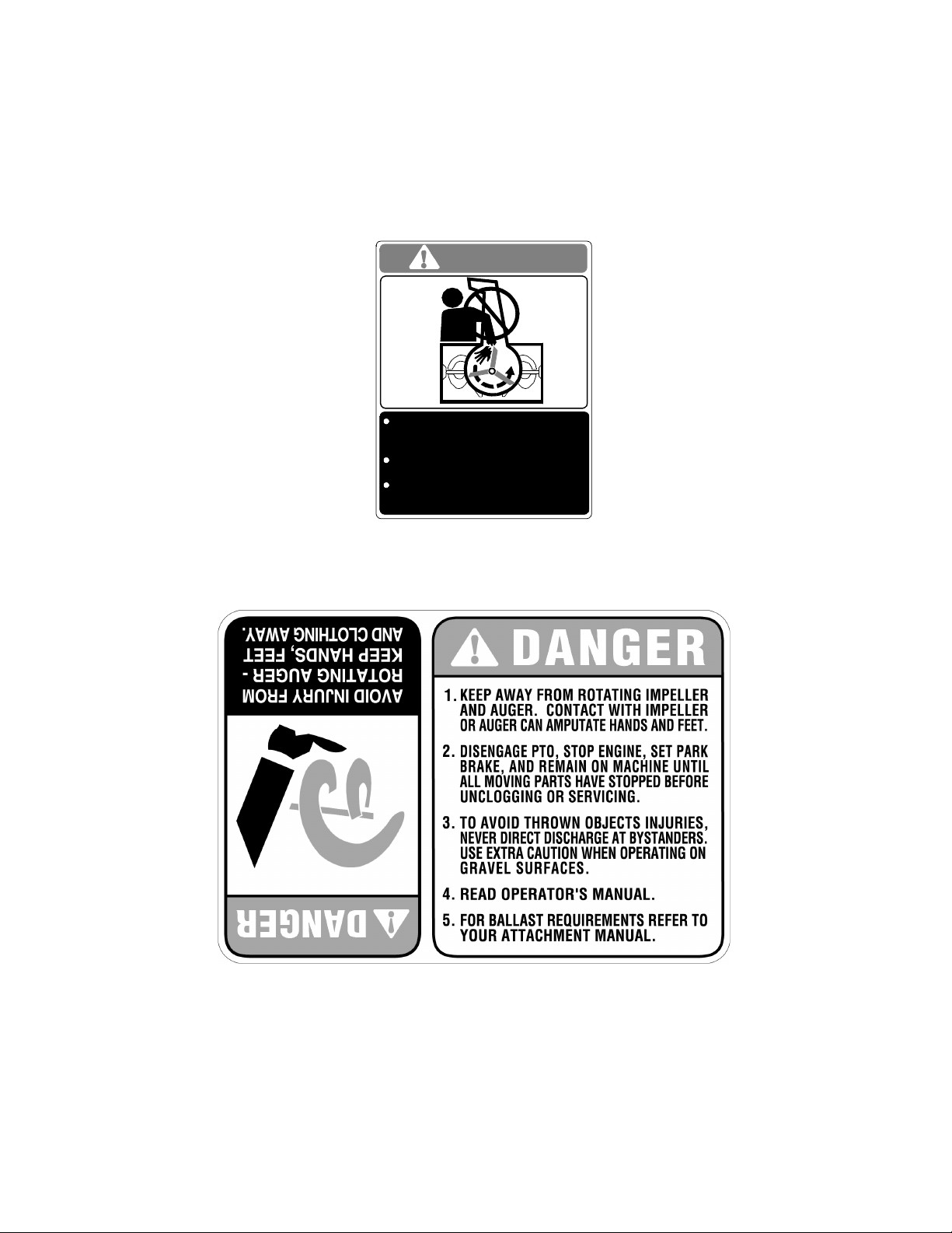
PRODUCT SAFETY GRAPHICS
1. Keep safety product graphics (decals) clean.
2. Replace any safety graphic that is damaged,
destroyed, missing, painted over or can no longer
be read.
3. Replacement safety graphics are available through
your Cub Cadet dealer.
DANGER
NEVER PUT HAND IN CHUTE. CONTACT WITH
ROTATING PARTS CAN AMPUTATE FINGERS
AND HANDS.
DO NOT UNCLOG DISCHARGE CHUTE WHILE
ENGINE IS RU NNING.
SHUT OFF ENGINE AND REMAI N ON
MACHINE UNTIL ALL MOVING PARTS
HAVE STOPPED BEFORE UNCLOGGING.
ON TOP OF DISCHARGE CHUTE
ON UPPER/REAR OF BLOWER HOUSING
DANGER W/SCRIPT — FACING OPERATOR
DANGER W/GRAPHIC — FACING FRONT OF SNOW THROWER
4
Page 5
TO THE OWNER
The Cub Cadet 45-inch Snow Thrower Attachment, Model Number 353, is designed for use on Cub Cadet Series
3000 Tractors. Contained in this manual are instructions for the installation and use of the snow thrower assembly
with these tractors.
Please keep this manual. The instructions in this manual explain the minor assembly required; installation and seasonal removal; and the adjustment, operating and maintenance procedures for the snow thrower assembly. Read
this manual carefully to familiarize yourself with the equipment before you install and operate the snow thrower.
The Front Hitch System, Model 190-343-100, MUST be installed on the tractor to allow installation of the
Snow Thrower Attachment.
The Hydraulic Angling Kit accessory, Model 190-288-100, for the Front Hitch System SHOULD NOT be used
with the Snow Thrower Attachment. Accidental activation of the angling system could cause damage to
both the snow thrower and tractor.
Read and observe all WARNING and CAUTION statements. They are included to provide for the protection of the
equipment installer and user, and to ensure prolonged service life of the equipment.
WARNING
To increase traction and stability of the tractor when using the snow thrower attachment, it is recommended that
rear wheel weights, or the rear weight bracket with a minimum of three suitcase weights, be installed on the
tractor. The Rear Wheel Weight Kit is available through your Cub Cadet dealer by ordering kit number 190-412.
The Rear Weight Bracket Kit is available as kit number 190-413, which includes only the bracket and mounting
hardware. The individual suitcase weights can be ordered under part number 759-3389.
NOTE
References to LEFT and RIGHT indicate the left and right sides of the tractor when facing forward in the driver’s
seat, unless specifically instructed to reference from a different position on the tractor. Reference to the FRONT
indicates the grille end of the tractor; to the REAR indicates the draw bar end.
5
Page 6

SECTION I. INTRODUCTION
This section will help you to become familiar with the components of the 45″ Snow Thrower Attachment, Model 353.
Select a firm level surface that is large enough to accommodate both the snow thrower assembly and the tractor w/
front hitch asssembly. After removing the upper crating material, remove the hardware pack and carefully roll the
snow thrower assembly rearward so that it rests on its bottom. When repositioning the snow thrower, use care not
to pinch or bind the chute crank support tube (D, Figure 1). Cut the tie strap(s) and remove any packaging material
from the chute crank rod /tilt handle / support tube assembly (C thru E, Figure 1), then position to the left side of the
snowthrower assembly. Refer to Figures 1 and 2 to confirm that all parts are present and to aquaint yourself with
the part descriptions. Throughout the instructions in this manual the parts shown in Figures 1 and 2 will be identified
by name, followed by either their callout letter or number in parenthesis.
REF.
NO. DESCRIPTION QTY.
E
C
A Snow Thrower Assembly 1
B Discharge Chute Assembly 1
C Chute Tilt Handle Assemby 1
D Chute Crank Support Tube Assembly 1
E Chute Crank Rod Assembly 1
F Chute Crank/ Mtg. Bracket Assembly 1
D
B
A
F
Figure 1
6
Page 7

CONTENTS OF HARDWARE PACK
3
1
4
2
REF.
PART
NO.
NUMBER DESCRIPTION QTY.
1 710-3022 Hex Cap Screw, 3/8-16 X 2.75 Lg GR5 2
2 712-0431 Hex Flange Lock Nut, 3/8-16 2
3 750-0748 Spacer, 3/8 ID x 1.0 OD x 1.25 Lg 2
4 714-0507 Cotter Pin, 3/32 X 3/4 Lg 1
5 725-0157 Cable Tie 1
6 711-1351 Split Locking Collar Assembly 1
7 710-0891 Shear Bolt, 5/16-18 X 1-3/4 Lg (Extra) 2
8 712-0429 Hex Insert Lock Nut, 5/16-18 (Extra) 2
6
5
7
8
Figure 2
7
Page 8

SECTION II. ASSEMBLY, INSTALLATION AND REMOVAL.
This section contains insructions for final assembly of
″ Snow Thrower, and the quick attachment steps
the 45
for installation and removal of the snow thrower. Before beginning, select a firm and level surface large
enough to accommodate both the snow thrower attachment and tractor.
The mower deck and its front lift bracket assembly
should be removed from the tractor before installing
the snow thrower. Refer to the mower deck Operator’s
Manual for deck removal instructions. To remove (or
install) the front lift bracket assembly while the Front
Hitch Kit Assembly is installed, proceed as follows:
WARNING
If the tractor has been recently operated, the
muffler, exhaust pipe, and surrounding areas
will be HOT. Allow the tractor to cool before
beginning installation.
• Loosen the hex lock nut (or wingnut knob) securing the pivot pin on the left side of front hitch.
• Remove the hex lock nut (or wingnut knob) and
pivot pin from the right side of the front hitch. Lower
the right side of the hitch pivot plate assembly.
• Push downward on the tractor’s quick attach rod
and remove the deck front lift bracket assembly.
• Reposition the hitch pivot plate and install the RH
pivot pin and hex lock nut (wing nut). Tighten the
left hex lock nut. Refer to the Front Hitch Operator’s Manual if necessary.
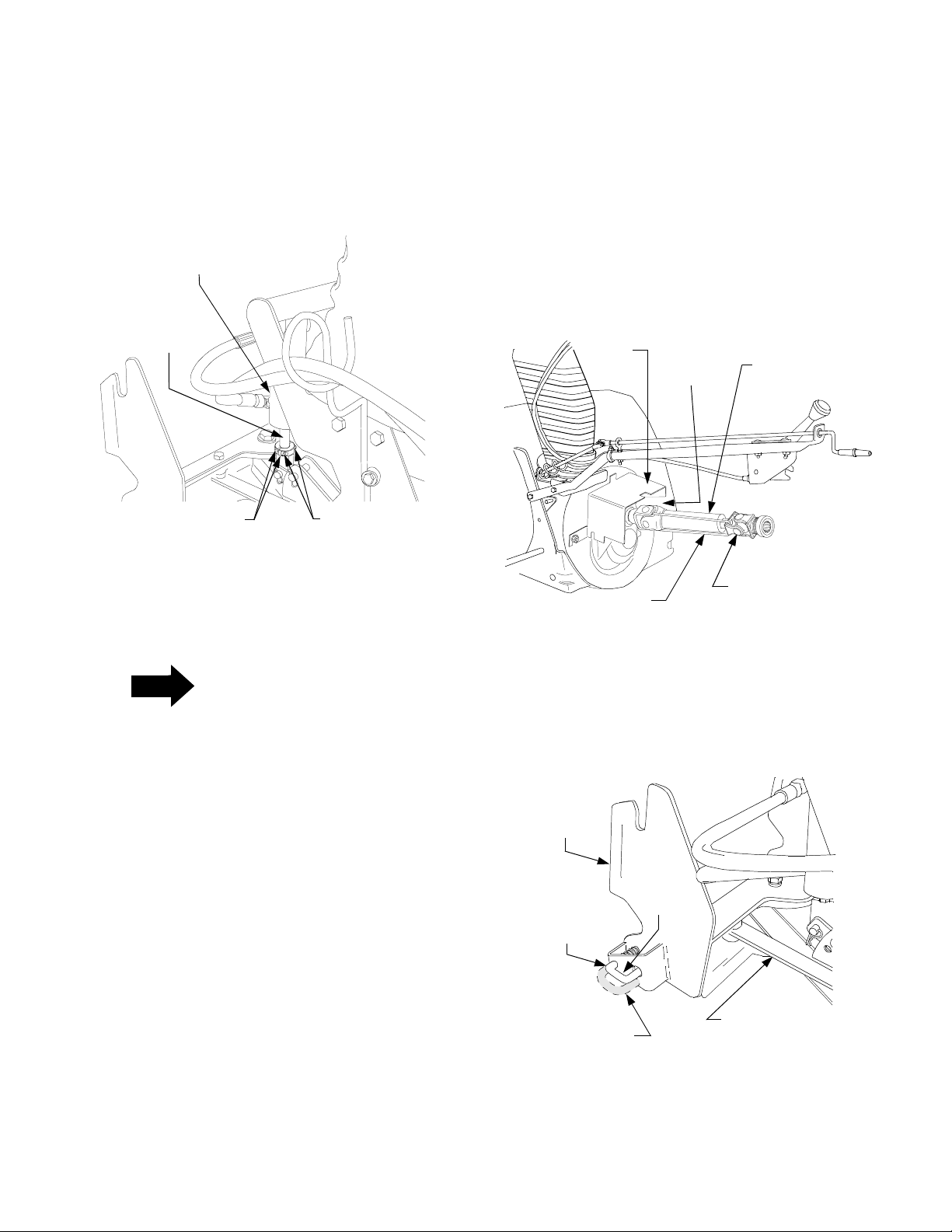
A. SNOW THROWER ASSEMBLY.
1. Insert the two hex cap screws (1) through the holes
at the forward end of the chute crank support
assembly (D), then slide a spacer (3) onto each
cap screw (1). See Figure 3.
2. Position the chute crank support tube (D) to insert
the screws (1) into the holes of the support tube
mntg. bracket and the housing mntg. bracket on
the left rear of the snow thrower housing. Secure
with the hex flange lock nuts (2). Refer to Figure 3.
3. Secure the tilt handle cables (C) to the inside of the
support tube (D) with the cable tie (5). See Figure
4. Cut excess length from the cable tie.
CABLE TIE
TILT HANDLE
CABLES
SUPPORT
TUBE
Figure 4
4. After making sure the chute crank rod is routed
through the eye bolt, insert the rod (E) into the
sleeve of the joint block on the chute crank assembly (F). Align the holes and secure the rod with the
cotter pin (4). See Figure 5.
EYE BOLT
HOUSING
MNTG. BRKT.
SPACERS
HEX CAP
SCREWS
CHUTE
CRANK
SUPPORT
Figure 3
HEX FLANGE
LOCK NUTS
SUPPORT
TUBE
MNTG. BRKT.
BUSHING
JOINT
BLOCK
COTTER PIN
CHUTE
CRANK
ROD
Figure 5
8
Page 9
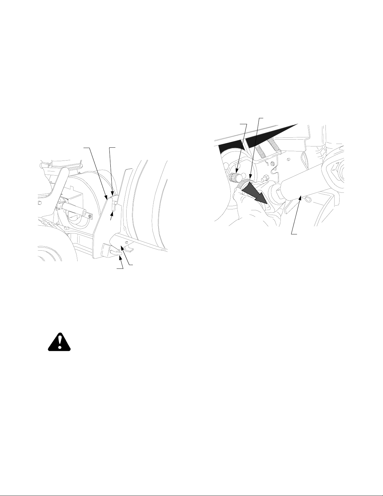
5. Remove the two socket hd. screws from the split
locking collar assembly (6) and install the collar
onto the bottom of the piston of the front hitch lift
cylinder. Secure with the two socket hd. screws
(See Figure 6). NOTE: If necessary, use the
tractor hydraulic system to slightly extend the
cylinder piston.
d. Install the front hitch strut (or manual angler-
set in center position) with the clevis pins and
internal cotter pins. Refer to the Angling Kit
Operator’s Manual if necessary.
2. Cut the cable tie holding the two halves of the drive
shaft together and slide the male half from the
female half (See Figure 7).
HITCH LIFT
CYLINDER
CYLINDER
PISTON
SPLIT LOCKING
COLLAR
SOCKET HEAD
SCREWS
Figure 6
B. INSTALLATION.
NOTE
If the Hydraulic Angling Kit (190-288-100) is
installed on the front hitch, accidental
actuation of the angling system could result
in damage to the snow thrower and/or
tractor. Whenever the snow thrower is
installed, it is recommended that the angling
cylinder be removed and replaced by either the
standard front hitch strut (See Figure 8) or the
manual angling kit (190-171), set in the center
position. The following step 1 applies ONLY to
units equipped with the hydraulic angling kit.
1. Remove the angling cylinder as follows:
a. Compress the locking collars of the female
fittings to disconnect the angling cylinder
hoses from the coupling assemblies on the left
side of the tractor.
b. Remove the hoses from the hose support rod.
c. Remove the internal cotter pins and clevis pins
fastening the angling cylinder to the pivot plate
and the front hitch yoke.
3. Pivot the female half shaft to the right and place in
the slot in the right side of the shaft cover (See
Figure 7).
SHAFT
COVER
CABLE TIE
COVER
SLOT
FEMALE
HALF
SHAFT
MALE
HALF
SHAFT
Figure 7
4. Make certain the support pins at the bottom of the
front hitch yoke are in the engaged position
(through holes in yoke). See Figure 8.
FRONT
HITCH
YOKE
LH HITCH
SUPPORT
ENGAGED
POSITION
DISENGAGED
POSITION
PIN
STANDARD FRONT
HITCH STRUT
(FIXED LENGTH)
Figure 8
9
Page 10
5. Start the tractor and align the front hitch yoke with
the attachment brackets on each side of the rear
blower housing (Refer to Figure 9).
6. Lower the front hitch yoke to clear the bottom of
the attachment bracket pins and carefully drive the
tractor forward to align the bracket pins with the
slots in the hitch yoke (See Figure 9).
7. Using the tractor hydraulic system to raise the front
hitch yoke, slowly lift the snow thrower until the
hitch support pins snap into the holes of the LH
and RH housing mntg. brackets (See Figure 9).
10. Slide the male half shaft into the female half
11. Compress the auto-lok collar on the snow thrower
drive shaft; then slide the shaft fully onto the PTO
shaft of the tractor and release the auto-lok collar
(See Figure 10). The drive shaft will lock onto the
PTO shaft if properly connected. NOTE: It may be
necessary to slightly rotate the drive shaft to align
the splines of the shafts.
AUTO-LOK
TRACTOR
PTO SHAFT
COLLAR
FRONT HITCH
YOKE
HITCH
SUPPORT PIN
RH ATTACHMENT
BRACKET
YOKE
SLOT
W/PIN
RH HOUSING
MTG. BRACKET
Figure 9
8. Stop the tractor engine and engage the parking
brake. Check that support pins are fully engaged in
the housing mntg. brackets holes (See Figure 9).
C
O
M
P
R
E
S
S
DRIVE SHAFT
ASSEMBLY
Figure 10
C. REMOVAL.
1. Move the snow thrower to its storage location.
2. Compress the auto-lok collar of the snow thrower
drive shaft and disconnect the shaft from the
tractor PTO shaft. Refer to Figure 10.
WARNING
If the tractor has been recently operated, the
muffler, exhaust pipe, and surrounding areas
will be HOT. Allow the tractor to cool before
beginning installation.
9. Pivot the female half shaft out of the cover slot and
position so that it points rearward between the
tractor frame. Refer to Figure 10.
3. Pull the hitch support pins outward and rotate to
lock in the disengaged position. Refer to Figure 8.
4. Using the tractor hydraulic system, lower the front
hitch yoke to disengage the snow thrower
attachment bracket pins from the slots of the hitch
yoke (Refer to Figure 9).
5. Back the tractor away from the snow thrower.
10
Page 11

SECTION III. ADJUSTMENTS AND OPERATION
A. ADJUSTMENTS
WARNING
If the snow thrower is to be used on gravel surfaces,
use extreme caution to avoid picking up gravel with
the shave plate or auger. Loose gravel can damage
the auger or housing, and could be thrown at high
speed by the impeller—causing possible injury to
bystanders or damage to surrounding objects.
1. Skid Shoe Adjustment
The skid shoes are mounted on each side of the
auger housing. They determine the distance the
shave plate is raised above the plowing surface.
The shave plate should be high for a gravel
driveway or other uneven surfaces and low for
paved surfaces. Adjust the skid shoes as follows:
a. Raise the snow thrower assembly off the
ground and place a block under each end of the
shave plate.
b. Loosen the hex insert lock nuts and bell
washers securing the skid shoes to the
housing.
2. Drift Cutters
Drift cutters on both sides of the auger housing can
be adjusted to the up position for a higher cut. Refer
to Figure 12 and proceed as follows:
a. Remove each drift cutter by removing the two
carriage bolts and hex insert lock nuts.
b. Turn the drift cutters to the up position and
secure with the carriage bolts and lock nuts as
shown in Figure 12.
DRIFT CUTTER
CARRIAGE
BOLT
HEX
INSERT
LOCK NUT
c. Move the skid shoes up or down to the desired
position and securely tighten the lock nuts.
Adjust both skid shoes to the same height.
Refer to Figure 11. Remove the blocks.
AUGER
HOUSING
SKID SHOE
HEX INSERT LOCK NUTS
AND BELL WASHERS
Figure 11
Figure 12
B. CONTROLS
The thrower controls are conveniently located to be
operated from the operator’s position on the tractor.
1. Lift Lever
The tractor hydraulics and front hitch system are
used to raise or lower the snow thrower. If installed
as recommended, the inner lift handle should
control the front hitch system. Pull the lift handle
upward (rearward) to raise the snow thrower. Push
the lift lever downward (forward) to lower the snow
thrower to the ground.
2. Front Power Take-Off (PTO)
The tractor front PTO switch controls engagement
of the snow thrower. To engage the auger, pull the
PTO switch handle upward. Push the PTO switch
handle downward to disengage the PTO and stop
the snow thrower auger.
11
Page 12

3. Discharge Chute Control Crank
The discharge chute control crank is located on the
left hand side of the snow thrower. The chute crank
controls the direction in which the snow is thrown.
The discharge radius is 190 degrees. Turn the
crank clockwise to rotate the discharge chute
opening toward the left, and counterclockwise to
rotate toward the right. Refer to Figure 13.
4. Chute Tilt Handle
The chute tilt handle assembly is also located on
the left hand side of the snow thrower assembly.
The upper chute of the discharge chute assembly
pivots downward when the tilt handle is pushed
forward, decreasing the distance snow is thrown.
Pulling the handle backwards pivots the upper
chute upward, increasing the distance snow is
thrown. Refer to Figure 13.
2. Before placing the snow thrower into operation:
a. Check all nuts and bolts for proper tightness.
Be sure that all parts are properly assembled.
b. Test all controls for smooth and proper
operation.
• Tractor lift handle and front hitch system
•PTO switch
• Discharge chute control crank assembly
• Discharge chute tilt control
c. Inspect the tractor and snow thrower to make
certain both are in good operating condition.
d. Fill the tractor’s fuel tank outdoors. Avoid
spilling fuel onto the engine or any other source
of heat or combustion. Do not fill the tank while
the engine is running. Wipe up any spilled fuel
before starting the engine.
UPPER CHUTE
DISCHARGE
CHUTE
CHUTE TILT
HANDLE
CHUTE
CRANK
ROD
Figure 13
C. OPERATION
The following steps describe methods for safe and
proper operation of this snow thrower. Refer to
“SAFE OPERATION PRACTICES” on page 2 of
this manual for additional safe operating practices.
1. The snow thrower is capable of handling heavy
snow conditions. Become fully familiar with all
aspects of both the tractor and snow thrower prior
to its usage. DO NOT remove any guards or covers
while operating the tractor and snow thrower.
WARNING
Whenever the snow thrower is installed on the front
of the tractor, usage of rear weights on the tractor is
recommended to counterbalance the weight of the
snow thrower and provide stability to the tractor.
See “TO THE OWNER” on page 5.
3. The auger speed is directly related to the engine
speed. For optimal snow removal and discharge,
maintain high engine R.P.M. (full throttle). Control
the tractor’s ground speed using the forward control
pedal (and cruise control feature, if desired). It is
recommended that the tractor be operated at a slow
ground speed for safer handling and efficient snow
removal.
4. Snow removal conditions vary greatly from light
fluffy snowfall to wet heavy snow. Therefore,
operating instructions must be flexible to fit the
conditions encountered. The operator must adapt
the tractor and snow thrower to the depth of snow,
wind direction, temperature and surface conditions.
5. In deep, drifted or banked snow, it will be necessary
to use full throttle and a slow ground speed. Drive
the auger into the snow, stop and allow the auger to
clear the snow. Repeat this method until a path is
cleared. On the second pass (and each succeeding
pass), overlap the preceding pass enough to allow
the auger to handle the volume of snow without
having to stop the tractor.
6. In extremely deep snow, the snow thrower may be
raised to the transport position, then slowly driven
into the deep snow to remove the top layers first.
However, do not drive the tractor into a snow bank
where the snow has not been cleared to the ground
level. Stop the tractor’s forward movement and
allow the auger to clear the snow. Reverse the
tractor and lower the snow thrower to the ground to
clear the remaining snow. Working with repeated
passes into and out of drifts, even the deepest snow
piles can be cleared.
12
Page 13

D. SPECIAL PRECAUTIONS
E. OPERATING TIPS
• Whenever possible, discharge snow down wind.
WARNING
If the snow thrower becomes plugged with snow or
jammed due to hitting a foreign object, immediately
disengage the PTO to stop the snow thrower, then
stop the tractor engine. If plugged, SAFELY (see
below) clear the chute before resuming operation.
WARNING
Never place your hand into the discharge chute
to remove plugged snow. Use a wooden dowel
rod, or similar object, to unclog the chute. Never
use your hand to remove any object jamming
the auger or impeller. The auger or impeller could
move when the obstruction is dislodged. Use an
appropriate tool (dowel rod, bar, etc.) to remove the
obstruction.
WARNING
• DO NOT attempt to clear ice or hard packedfrozen snow.
• Always overlap each pass slightly to assure
complete snow removal.
• A frozen or stuck auger or chute must be broken
loose or thawed with care. When attempting to
loosen a frozen or jammed auger, shut off the
tractor engine and disconnect the spark plug
wire(s). Never attempt to clear the snow
thrower at any time with the tractor engine
running.
NOTE
When the snow thrower and tractor are not in use,
lower the snow thrower to the ground to eliminate
the excess weight from the lift system and the front
tires.
WARNING
If the auger is jammed or bent from hitting a
foreign object, disengage the PTO and stop the
tractor engine. Remove the spark plug wires from
the spark plugs and then remove the foreign
object from the auger. If damage is noted, repair
or replace damaged components prior to
continuing operation. Reconnect the spark plug
wires and resume operation.
When making any adjustments, disengage the PTO
and turn the tractor engine off.
13
Page 14
SECTION IV. MAINTENANCE
Section IV describes maintenance procedures designed to keep your snow thrower in good operating
condition.
SHAVE PLATE AND SKID SHOES
The shave plate and skid shoes on the bottom of the
snow thrower housing are subject to wear. They should
be periodically checked for wear and replaced when
necessary. Failure to do so will result in damage to the
housing.
1. Replace the shave plate as follows:
a. Remove the seven carriage bolts and hex
flange lock nuts that secure the shave plate to
the bottom of the housing.
b. Remove the rear most carriage bolt, bell
washer and hex insert lock nut securing the
back end of each skid shoe to the sides of the
housing.
NOTE
If necessary to ease sliding the shave plate out
of position on the housing, loosen the four
remaining hex insert lock nuts which secure
the skid shoes to the housing.
c. Slide the shave plate out of the off-set slot of
the housing, and from between the skid shoes
and side panels of the housing.
d. With the mounting holes toward the back, slide
the new shave plate into position and secure
with the fasteners removed previously.
2. The skid shoes are reversible for longer life. Remove the carriage bolts, bell washers and hex insert lock nuts fastening the skid shoes to the
housing. Turn the shoes over and/or reverse sides
to ensure even wear and extend their service life.
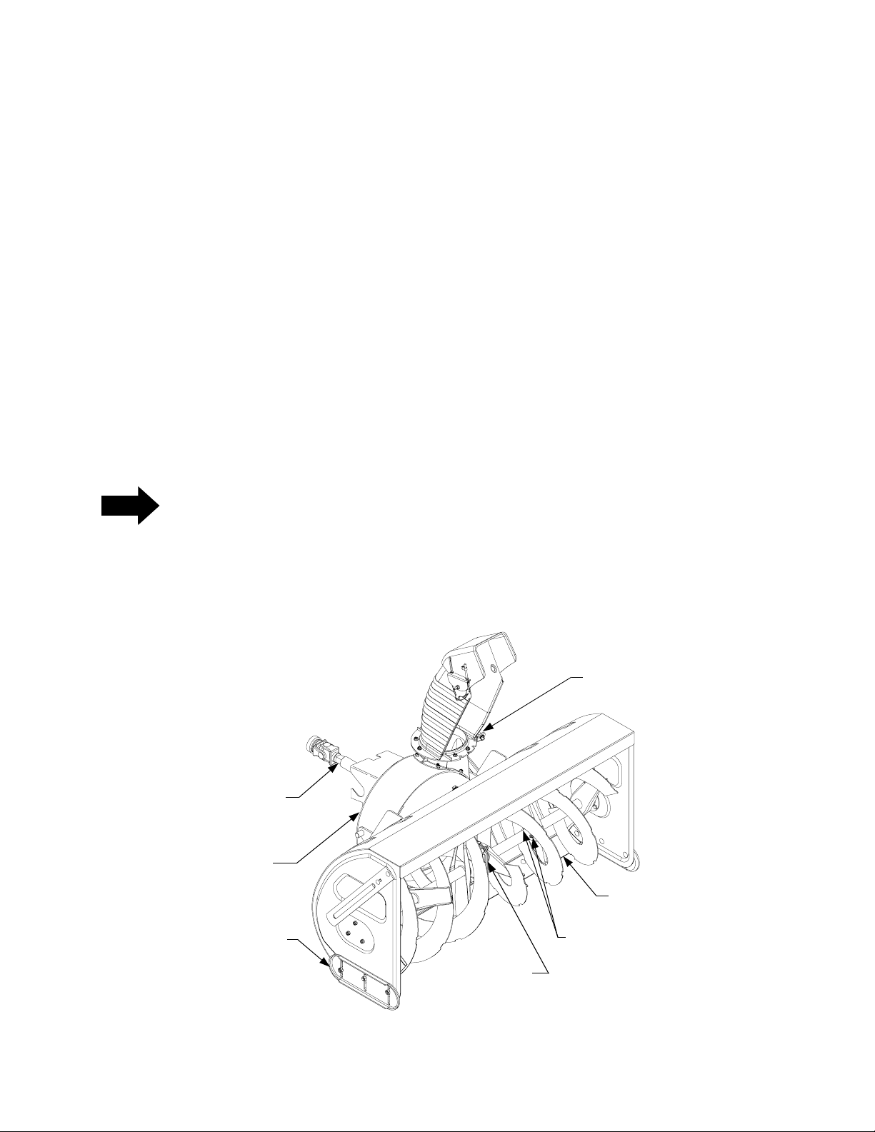
AUGERS
1. The augers are secured to the auger shaft with two
shear bolts and hex insert lock nuts. Refer to Figure 14. If the auger is suddenly jammed by a foreign object or ice chunk, the bolts are designed to
shear — minimizing potential damage to the gear
boxes.
2. If the augers will not turn, check the bolts to see if
they have sheared. Two replacement shear bolts
(7) and hex insert lock nuts (8) have been provided
with the snow thrower. For future use, order part
number 710-0891 for replacement shear bolts and
712-0429 for the lock nuts.
DRIVE SHAFT
SPROCKET BOX
ASSEMBLY
(BELOW COVER)
SKID SHOE
CHUTE CRANK
SPIRAL GEAR
SHAVE PLATE
SHEAR BOLT AND HEX
INSERT LOCK NUT
(BOTH SIDES)
AUGER GEAR
BOX ASSEMBLY
Figure 14
14
Page 15

LUBRICATION
1. The auger gear box is lubricated with grease at the
factory and is neither externally servicable, nor
requires checking. If disassembled for any reason,
lubricate with 2.5 ounces (by weight) of Alvania
grease, part number 737-0168A. Before
reassembling, remove old sealant and apply
Loctite Ultra Grey (759-3746) sealant or
equivalent.
2. The sprocket box assembly is also neither
externally servicable, nor requires checking. If
disassembled for any reason, lubricate with 5.0
ounces (by weight) of Benalene grease, part
number 737-0300A. Before reassembling, remove
old sealant and apply Loctite Ultra Grey (759-
3746) sealant or equivalent.
3. Apply penetrating oil to the cables of the chute tilt
handle assembly at least once a season.
4. Apply a good grade of spray lubricant to the universal joint of the chute crank, and to the pivot of the
chute tilt handle at least once a season.
5. Lubricate the chute crank spiral gear with a multipurpose automotive grease once a year.
6. Lubricate the telescoping square spindle of the
drive shaft (rear half) using 251H EP grease or an
equivalent No. 2 multi-purpose lithium grease
once a year.
7. Lubricate the bearings at each end of the auger
shaft with oil or spray lubricant at least once a season.
8. Although not required, it is advisable to remove the
auger shear bolts at least once a season and
spray penetrating oil, or similar lubricant, between
the auger tubes and auger shaft.
OFF-SEASON STORAGE
At the end of the snow season the following steps are
recommended:
1. Remove the snow thrower assembly from the tractor.
2. Wash off any salt deposits which may have dried
on the snow thrower housing. Paint, or cover with
a light coat of oil, any exposed metal surfaces.
3. Lubricate bearings and pivot points with a good
grade of spray lubricant.
4. Store the snow thrower in a dry place.
15
Page 16

MANUFACTURER’S LIMITED WARRANTY FOR:
TWO-YEAR RESIDENTIAL
ONE-YEAR COMMERCIAL
Proper maintenance of your Cub Cadet equipment is the owner’s responsibility. Follow the instructions in your
operator’s manual for correct lubricants and maintenance schedule. Your Cub Cadet dealer carries a complete
line of quality lubricants and filters for your equipment’s engine, transmission, chassis and attachments.
Riding mowers, lawn tractors, garden tractors, Cub Cadet
attachments and home maintenance products
This limited warranty for residential users, covers any defect in materials or workmanship in your Cub Cadet
equipment for two years from the date of purchase for the first user purchaser. We will replace or repair any part
or parts without charge through your authorized Cub Cadet dealer.
Batteries have a one-year prorated limited warranty with 100% replacement during the first three months.
V-belts for either the traction drive or any attachments are covered for one year only.
Cub Cadet equipment used commercially is warranted for one year only.
(Commercial use is defined as either having hired operators or used for income producing purposes.)
Items not covered
The warranty does not cover routine maintenance items such as lubricants, filters (oil, fuel, air and hydraulic),
cleaning, tune-ups, brake and/or clutch inspection, adjustments made as part of normal maintenance, blade
sharpening, set-up, abuse, accidents and normal wear. It does not cover incidental costs such as transporting
your equipment to and from the dealer, telephone charges or renting a product temporarily to replace a warranted
product.
There is no other express warranty.
How to obtain service
Contact your authorized Cub Cadet servicing dealer who sold you your Cub Cadet equipment. If this dealer is not
available, see the Consumer Yellow Pages under “lawn mowers” for the name of a dealer near you.
If you need further assistance in finding an authorized Cub Cadet servicing dealer, contact:
Cub Cadet Corporation
Post Office Box 368023
Cleveland, Ohio 44136
How does state law apply?
This limited warranty gives you specific legal rights, and you may also have other rights which vary from state to
state.
 Loading...