

Page 1

Operator’s Manual
HYDRAULIC FRONT
ATTACHMENTHITCH
For Cub Cadet Series 3000 Tractors
(Optional Manual Angling Kit 190-171-100)
INSTALLATION
INSTRUCTIONS
Model Number
343
IMPORTANT:
READ SAFETY RULES AND INSTRUCTIONS CAREFULLY
CUB CADET LLC P.O. BOX 361131 CLEVELAND, OHIO 44136-0019 [www.cubcadet.com]
PRINTED IN U.S.A. FORM NO. 770-0843C
(11/03)ECO 07686
Page 2

NOTES
2
Page 3
CONTENTS
Section Page
Safe Operation Practices ................................. ... ............................................. ... .......... 3
To The Owner ............................................................................................................... 3
l Front Hitch Components ............................................................................................... 4
Il Tractor Preparation ................................... .................................................................... 6
lll Installation .................................................................................................................... 9
IV Tractor Reassembly .................................... .... ............................................. ... ............. 19
V Removal and Maintenance ........................................................................................... 21
VI Optional Manual Angling Kit (190-171) ......................................................................... 22
Warranty .......................................................................................................................24
WARNING
The tractors which use this front hitch atta chment are equ ipped wit h an inter na l combu stion eng ine and sh ould
not be used on or near any unimproved forest-covered, brush-covered, or grass-covered land unless the
engine’s exhaust system is equipped with a spark arrester meeting applicable local or state laws (if any). If a
spark arrester is used, it should be maintained in effective working order by the operator.
In the State of California, the above is re quired by la w (Se cti on 4 442 of t he Califor nia Pub lic Reso ur ce s Code ).
Other States may have similar laws. Federal laws apply to federal lands. A spark arrester muffle r is available at
your nearest engine authorized service center.
IMPORTANT
THIS SYMBOL POINTS OUT IMPORTANT SAFETY INSTRUCTIONS WHICH, IF NOT FOLLOWED,
COULD ENDANGER THE PERSONAL SAFETY AND/OR PROPERTY OF YOURSELF AND
OTHERS. READ AND FOLLOW ALL INSTRUCTIONS IN THIS MANUAL BEFORE ATTEMPTING
TO OPERATE YOUR UNIT. FAILURE TO COMPLY WITH THESE INSTRUCTIONS MAY RESULT
IN PERSONAL INJURY. WHEN YOU SEE THIS SYMBOL— HEED ITS WARNING.
SAFE OPERATION PRACTICES
TO THE OWNER
This manual contains instructions for installation of the Front Hitch System, Model Number 190-343, on the Cub
Cadet Series 3000 Tractors. Carefully read all sections and study the illustrations to ensure proper installation.
If the optional Hydraulic Angling Kit (190-288) is going to be installed on the Front Hitch System, its
installation procedures should be performed in conjunction with those of this attachment.
Read and observe all WARNING and CAUTION statements. They are included to provide for the protection of the
equipment installer and user, and to ensure the prolonged service life of the equipment.
NOTE
References to LEFT and RIGHT indicate th e left and right sides of the tractor when facing fo rward in the
operator’s position. Reference to the FRONT indicates the grille end; to the REAR the drawbar end.
CALLING FOR SERVICE
If you are having difficulty assembling this product or if you have any question regarding the operation or
maintenance of this equipment, contact your dealer. If you need help locating a dealer in your area, contact the
Customer Dealer Referral Line by calling:
1-877-282-8684
3
Page 4
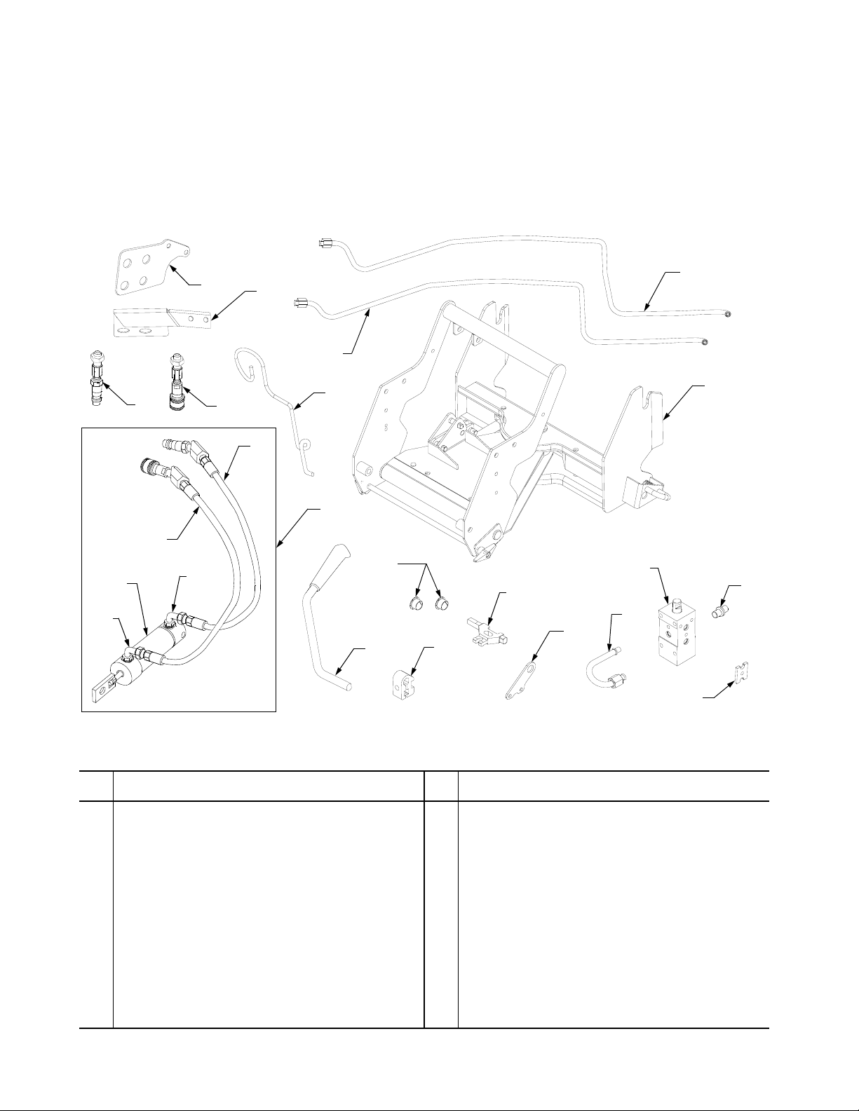
SECTION I. FRONT HITCH COMPONENTS
Before beginning installation of the Front Hitch
System, remove all parts from the shipping container.
Refer to Figures 1 and 2 to confirm that all parts are
present and to familiarize yourself with the part
descriptions.
22
6
8
10
11
7
5
1
Throughout the installation instructions in this manual,
the component part name is followed by the reference
letter or number in parentheses to aid in identification.
9
12
4
2
3
3
13
14
Figure 1
Ref.
No. Part No. Description Qty.
1 N/A Cylinder and Hose Assembly ....... 1
2 717-3456 Lift Cylinder .................................. 1
3 727-3012 90° Fitting w/O-Ring ..................... 2
4 N/A Hydraulic Hose Ass’y. ..................
(w/Female Coupling)
5 N/A Hydraulic Hose Ass’y. ..................
(w/ Male Coupling)
6 N/A Hydraulic Coupling Ass’y. - Male . 1
7 N/A Hydraulic Coupling Ass’y. - Female 1
8 703-3184 Fitting Bulkhead — For use with
tractors having welded running
board brackets.
9 727-3142 Hydraulic Lift Tube - Down ........... 1
10 727-3141 Hydraulic Lift Tube - Up ............... 1
1
1
1
19
15
18
17
16
21
Ref.
No. Part No. Description Qty.
11 747-3372 Hose Support Rod ........................ 1
12 N/A Front Hitch Ass’y. ......................... 1
13 741-0491 Nylon Flange Bearing ................... 2
14 747-3350 Handle, Aux. Valve #1 .................. 1
15 748-3081 Lift Link ......................................... 1
16 748-3082 Handle Clamp ............................... 1
17 703-3154 Lift Valve Bracket .......................... 1
18 727-3149 Hydro Return Tube, Aux. Valve #1 1
19 717-3452 Hydraulic Valve Assembly ............ 1
20 711-3294 Valve Adapter ............................... 1
21 703-1803 Double Valve Clamp ..................... 1
22 703-3442 Fitting Bulkhead — For use with
tractors having bolt up running
board brackets.
20
1
4
Page 5
A
B
C
D
E
F
G
H
K
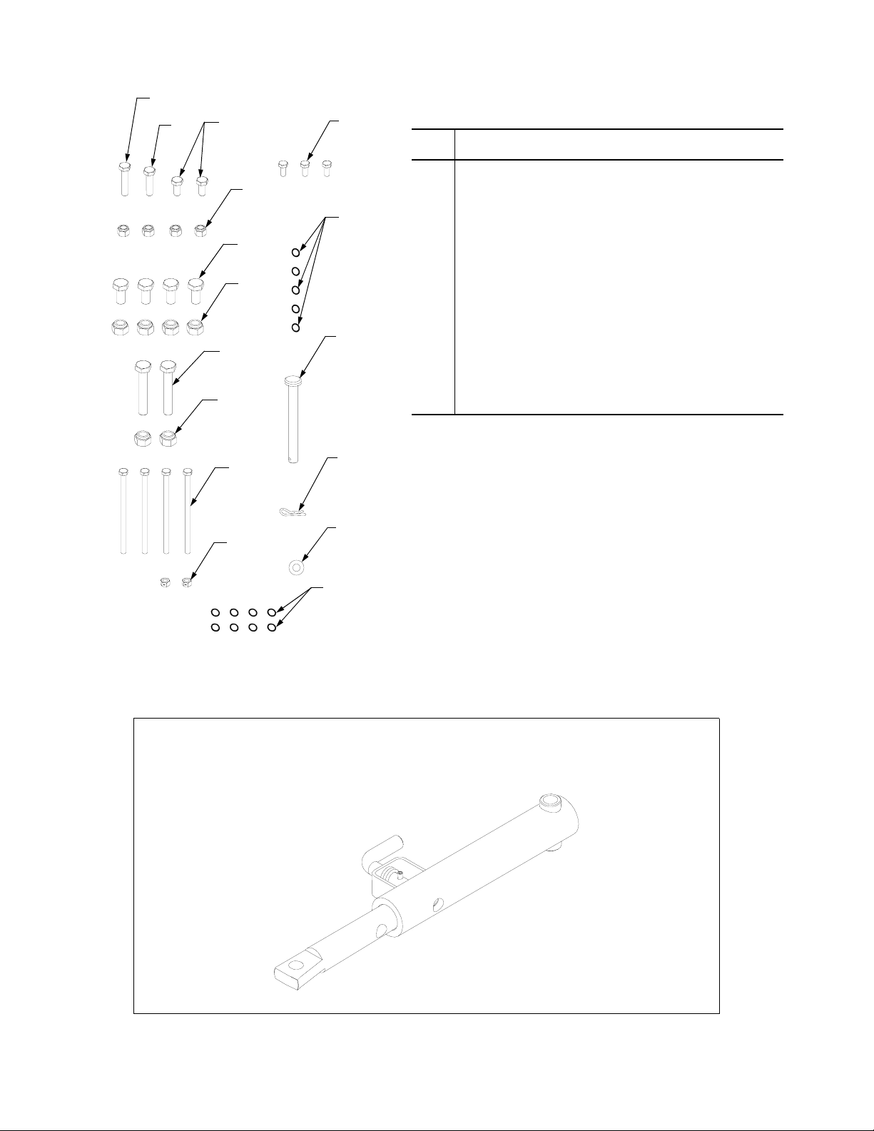
Ref.
No. Part No. Description Qty.
A 710-0805 Hex Cap Screw, 5/16-18 x .1.5 ..... 1
B 710-0528 Hex Cap Screw, 5/16-18 x 1.25 1
C 710-3025 Hex Cap Screw, 5/16-18 x.625 GR5 2
L
M
D 712-0429 Hex Insert Lock Nut, 5/16-18 ........ 4
E 710-3131 Hex Cap Screw, 1/2-13 x 1.0 GR5 4
F 712-3083 Hex Insert Lock Nut, 1/2-13 .......... 4
G 710-3104 Hex Cap Screw, 1/2-13 x 2.25 GR5 2
H 712-3083 Hex Insert Lock Nut, 1/2-13 .......... 2
I 710-1058 Hex Cap Screw, 1/4-20 x 4.0 ........ 4
J 712-0291 Hex Lock Nut, 1/4-20 .................... 2
K 710-3013 Hex Cap Screw, 1/4 -20 x 1/2 ....... 3
L 721-3021 O-Ring, .301 ID x .070 Dia ........... 5
M 711-0578 Clevis Pin ...................................... 1
N 714-0145 Internal Cotter Pin ......................... 1
0 736-0159 Flat Washer, .349 x .879 x .063 .... 1
P 721-0492 O-ring, Backup .............................. 8
I
J
N
O
P
Figure 2
MODEL 190-171-100
OPTIONAL MANUAL ANGLING KIT
Figure 3
5
Page 6
SECTION II. TRACTOR PREPARATION
This section contains instructions for preparing the
tractor for installation of the Front Hitch System.
WARNING
Place the tractor on a firm and level surface,
disengage the PTO, and turn the ignition switch
to the OFF position. Chock the front wheels to
prevent the tractor from rolling in either
direction.
WARNING
Allow the tractor to cool if it has been recently
operated.
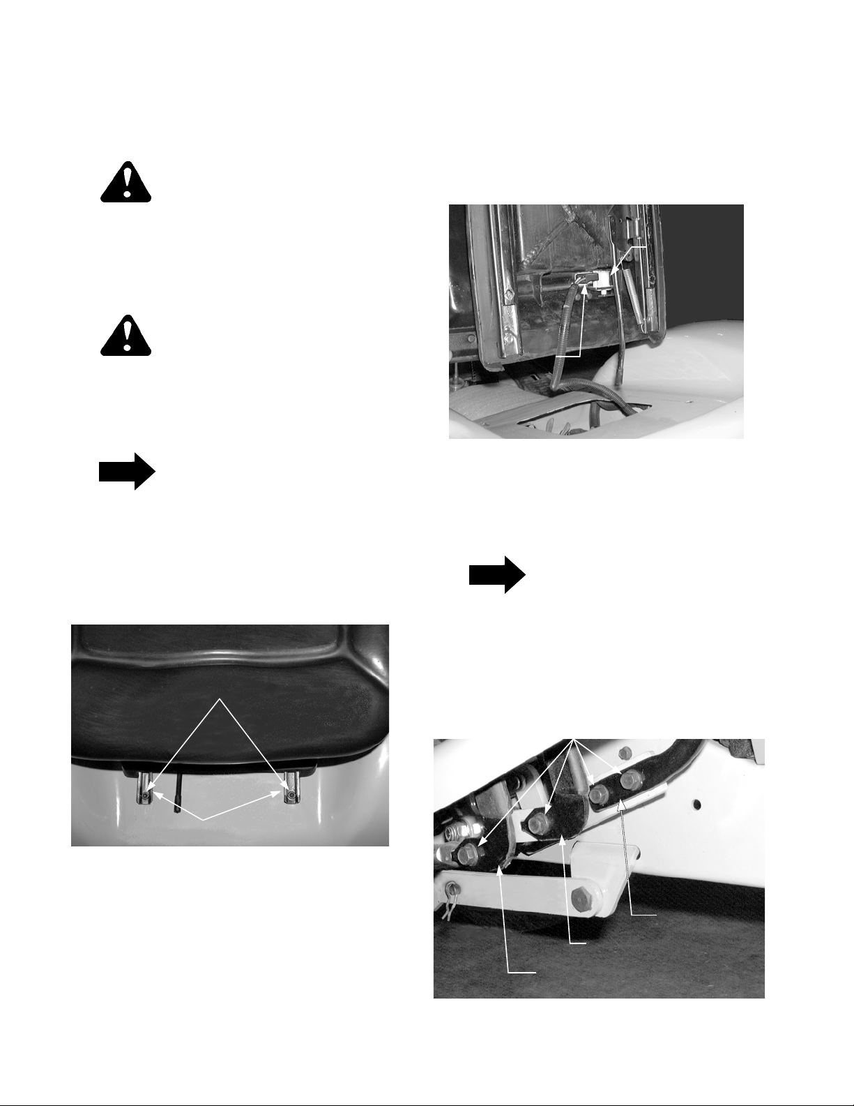
A. REMOVE THE TRACTOR SEAT.
NOTE
On some tractors, socket head screws were
used to secure the seat slide channels to the
tractor frame.
4. Lift the locking tab of the connector and unplug the
wire harness connector from the seat switch (See
Figure 5).
5. Place the seat assembly to the side.
SEAT
SWITCH
HARNESS
CONNECTOR
Figure 5
B. REMOVE THE FENDER AND RUNNING
BOARD ASSEMBLY
1. Slide the seat rearward and remove the two torx
head screws (or socket hd. s crews) from the seat
slide channels (See Figure 4).
TORX HEAD SCREWS
(OR SOCKET HD. SCREWS)
SLIDE CHANNELS
Figure 4
2. Slide the seat forward and remove the two rear
torx head screws ( or socket hd. screws) from the
slide channels.
3. Grasp the rear of seat base, then carefully lift and
tip the complete seat assembly so that it rests on
its side. Use care to avoid scratching the paint.
NOTE
The front hitch attachment can be installed
without removing the tractor fenders. However,
because of limited access and to ensure proper
installation, it is recommended that the fender
and running board assembly be removed from
the tractor.
HEX WASH. HD. TAPP SCREWS
BRAKE PEDAL
FORWARD PEDAL
REVERSE PEDAL
Figure 6
6
Page 7
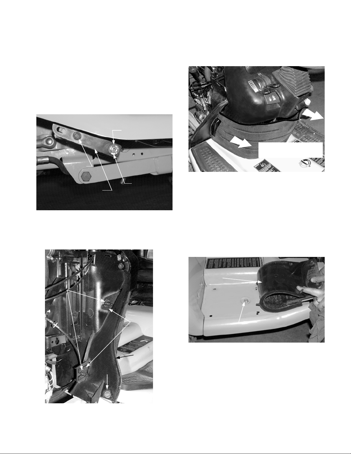
1. From beneath the right running board, remove the
hex wash. hd. tapp screws and remove in the
following order: the reverse control pedal, forward
control pedal, and the brake pedal (See Figure 6).
NOTE: The following step 2 app lies only to tractor s
equipped with the Diff-Lock feature.
2. From beneath the left running board, remove the
retaining ring and hex wash. hd. tapp screw to remove the diff-lock pedal. Use care to avoid losing
the nylon bearing in the pedal (See Figure 7).
RETAINING
RING
HEX WASH. HD.
TAPP SCREW
NYLON
DIFF - LOCK
PEDAL
BEARING
4. Loosen the four wing nuts securing the dash
screen to both sides of the bulkhead; then slide t he
screen rearward and out from below the dash
panel (See Figures 8 and 9)
SLIDE SCREEN FROM
BELOW DASH PANEL
Figure 9
Figure 7
3. Raise the hood and remove the side panels per the
instructions in the tractor Operator’s Manual.
WING
NUTS
SCREEN
TABS
BULKHEAD
HEX
SCREW
5. Remove the two hex screws securing the bottom
of the bulkhead and the front of the running board
to both sides of the frame (See Figure 8).
6. Carefully pull up the rear of the RH and LH foot
pads and remove the hex screws securing the
running board to the frame (See Figure 10).
RH FOOT
PAD
HEX SCREW
Figure 10
7. From underneath the rear fender, turn the four tail
light sockets counterclockwise (approximately 1/4
turn) until aligned with the notches of the reflector
housing and pull the sockets from housings. Be
careful to avoid pulling the bulbs from the sockets.
Figure 8
8. Remove the cap from the fuel tank.
7
Page 8
WARNING
Use care when handling the fender and running
board assembly. The edges could cause cuts to
the skin.
9. With the help of an assistant, lift the front of the
running board off the frame brackets, then raise
the rear fender over the neck of the fuel tank and
the lift handle to remove the fender assembly.
10. Reinstall the cap onto the fuel tank.
rearward as described in the following section D
to increase the space. If the o ptional Hydraulic
Angling Kit (190-288-100) is also being
installed, the tank must be moved rearward.
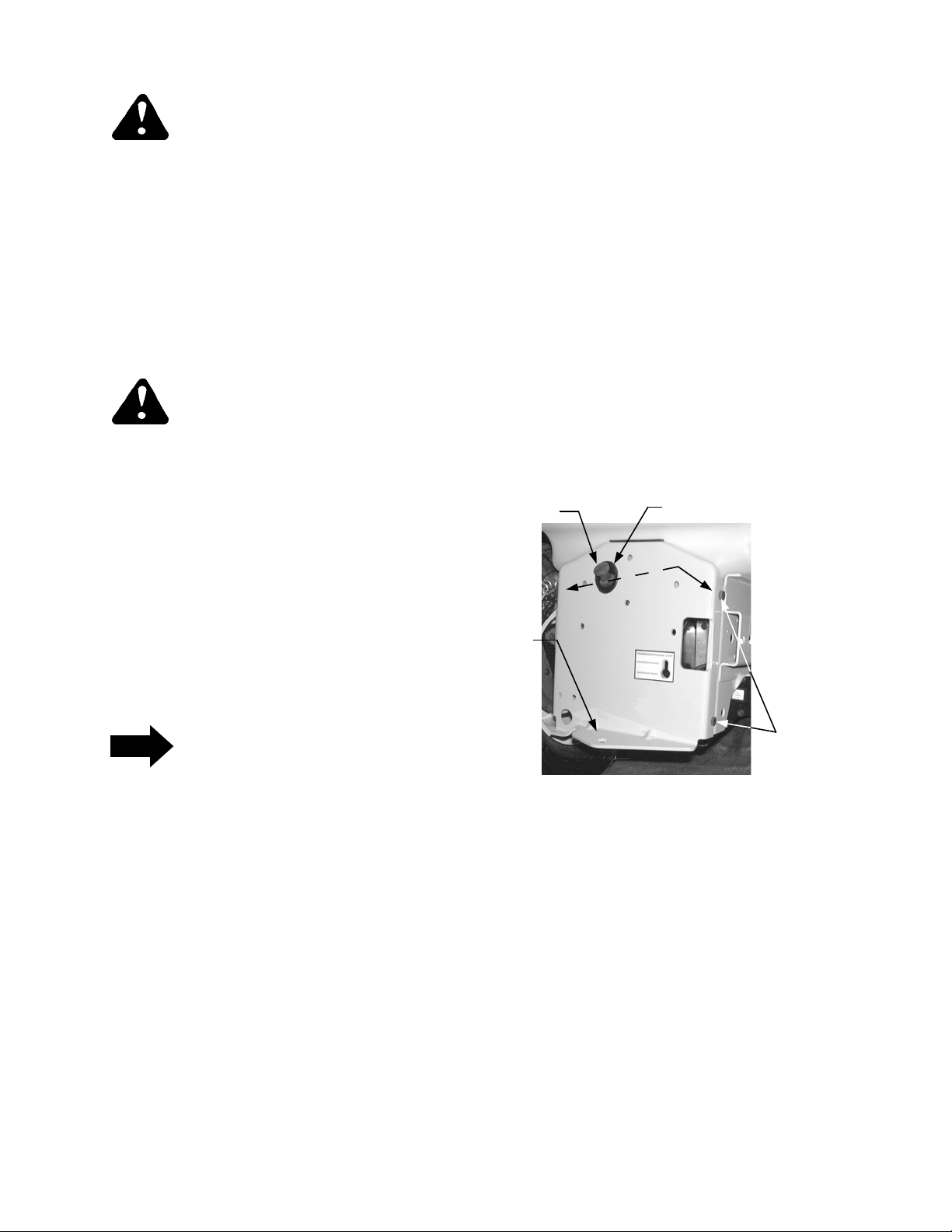
D. MOVE THE FUEL TANK REARWARD.
1. Remove th e two hex cap screws and hex flange
lock nuts securing the top of the hitch plate to the
frame (See Figure 11).
2. Loosen, but do not remove, the two hex cap
screws and flange nuts at the bottom of the hitch
plate
C. REMOVE THE LEFT REAR WHEEL.
WARNING
Ensure the front wheels are chocked before
raising the rear of the tractor. Use jack stands to
support the tractor; do not work on the tractor
when supported only by the jack.
1. Use a jack placed under the rear hitch plate to
raise the rear end of the tractor.
2. Position jack stands under each side of the frame,
just forward of the rear wheels. Lower the tractor
onto the jack stands and remove the jack.
3. Remove the lug nuts to remove the left rear wheel
assembly.
NOTE
The position of the fuel tank limits the working
space available for installing the hydraulic valve
included in this kit. Although not required, it is
recommended that the fuel tank be moved
3. Tip the top of the hitch plate back as needed to
slide the fuel tank rearward. NOTE: The
transmission oil fill tube/dipstick may be pulled
from the transmission housing when the hitch plate
is tipped. If so, plug or cover the hole in the
transmission to prevent dirt or debris from
entering.
DIPSTICK
HITCH
PLATE
OIL FILL TUBE
FLANGE LOCK NUTS
(NOT SHOWN)
HEX CAP
SCREWS
(BOTH SIDES)
Figure 11
8
Page 9

SECTION III. INSTALLATION
This section contains instructions for installing the
Front Hitch System on the tractor. If the optional
Hydraulic Angling Kit (190-288-100) is also being
installed, refer to the installation instructions in its
Operator’s Manual as you complete each of the
following steps. Some of the instructions for
installation of the Angling Kit will supersede or
supplement instructions for the Front Hitch.
REAR VALVE
MTG. BRACKET
HEX SCREW
VALVE CLAMP
HYDRAULIC
VALVE
A. INSTALL THE HYDRAULIC VALVE.
WARNING
Allow the tractor to cool if recently operated.
CAUTION
Position a suitable container to catch any oil leakage that may occur when disconnecting the hydraullic lines. Obey all applicable laws for disposal
of oil.
NOTE
Early production tractors were built with a standard O-ring and a backup O-ri ng on the hydraulic lines at their connections to the hydraulic
valve. When disconnecting the hydraulic lin es,
make certain to note whether there are one or
two O-rings at each connection (O-rings may
stick in valve bores). Extra backup O-rings have
been provided with this kit for use if needed.
The backup rings can be used to ensure tight
connections at the hydraulic valves.
HEX SCREW
AND LOCK NUT
HYDRO
RETURN
TUBE
HEX LOCK
NUTS
HEX SCREW
AND LOCK NUT
‘T’ FITTING
COUPLING NUT
Figure 12
REAR VALVE
MTG. BRACKET
VALVE CLAMP
HEX SCREW
HYDRO
RETURN
HOSE
Figure 13
NOTE
Tractors built after Mfg. Code 1D178G20023
are equipped with a flexible hose instead of the
hard hydro return tube (See Figure 13). If
equipped with the flexible hose, skip step 1 and
refer to step 2
1. Mfg. Code 1D178G20022 and Before. Secure
the ‘T’ fitting to avoid damaging the hydraulic lines
and loosen the coupling nut; then remove the hex
screw and valve clamp to remove the standard
hydro return tube (See Figure 12) . Re move th e Oring and backup ring (if applicable) from the tube.
Retain the valve clamp, screw and backup ring.
2. Mfg. Code 1D178G20023 and After. Remove the
hex screw and valve clamp to disconnect the
hydro return hose from the valve (See Figure 13).
Use care to avoid losing the O-Ring and backup
ring (if applicable) from the end of the hose. Retain
the valve clamp and screw.
3. Remove the hex cap screw and lock nut fastening
the rear valve mtg. bracket to the tractor frame
(See Figure 12 or 13). Retain the fasteners.
4. Remove the two hex screws and lock nuts
securing the hydraulic valve between the front and
rear valve mtg. brackets (See Figure 13 and 14).
Remove and retain the rear mtg. brac ket and lock
nuts.
9
Page 10

NOTE
DOUBLE VALVE
CLAMP
Tractors built prior to Mfg. Code 1H018G have
the standard center lift hydraulic lin es ro uted to
the outside of the frame. The standard lines
should be moved to the inside of the frame to
provide space for routing the front hitch
hydraulic lines. The following step 5 applies
ONLY to these tractors.
5. Move the standard lift cylinder lines to the inside of
the frame as follows:
a. Remove the hex screw and valve clamp secur-
ing the hydraulic tube in the front of the valve
(See Figure 14). Use care to avoid losing the
O-Ring and backup ring (if applicable) from the
end of the tube.
b. Remove the two hex cap screws and slide the
lift valve bracket off the lift link (See Figure 14).
Use care to avoid losing the nylon bearing.
NYLON BEARING
HEX CAP
SCREW
LIFT VALVE BRACKET
LIFT LINK
HEX SCREW
HYDRAULIC
LINES
Figure 15
LIFT LINK SLOT
HYDRAULIC
TUBE
HEX
SCREW
VALVE
CLAMP
HEX SCREW
Figure 14
c. After first noting the position of the hydraulic
lines (top outlet port to front of cylinder) remove the hex screw and double valve clamp to
disconnect the hydraulic lines from the valve
(See Figure 15). Use care to avoid losing the
O-Rings and backup rings (if applicab le) from
the end of the hoses.
d. Slide the valve rearward off the hydraulic tube
and out of the slot in the lift link (See Figu re 16)
to remove from the tractor.
O-RING(S)
Figure 16
e. While holding the valve spool in place, rotate
the body of the valve assembly 180° so that
the outlet ports face inward and the valve
spool arrow points rearward(See Figure 17).
ARROW
VALVE
BODY
TOWARD
TRACTOR
FRAME
VALVE
SPOOL
OUTLET
PORTS
TOWARD
INSIDE OF
TRACTOR
Figure 17
10
Page 11

f. If not already installed, install a backup O-ring
(P) between the existing O-ring and the fl ange
of the front hydraulic tube.
g. With the out let ports facing inward, align the
valve assembly with the front hydraulic tube
and the slot ot the lift link, then slide the valve
into position in the tractor.
h. Slide the lift valve bracket w/nylon bearing
onto the lift link and secure with the two hex
cap screws (See Figure 18).
i. Secure the front hydraulic tube with the valve
clamp and hex screw (See Figure 18).
6. Slide a backup O-ring (P) and O-Ring (L) onto
each end of the valve adapter (20), and insert the
valve adapter into the rear port of the standard
center lift valve (See Figure 20).
NYLON
FLANGE
BEARING
O-RING
BACKUP RING
HEX CAP
SCREW
VALVE
CLAMP
LIFT VALVE BRACKET
NYLON BEARING
LIFT
LINK
HEX
SCREW
Figure 18
j. If not already installed, install a backup O-ring
(P) between the existing O-ring and the fl ange
on each of the hydraulic lines, then insert the
lines into their respective outlet ports as noted
previously. Secure with the double valve
clamp and hex screw (See Figure 19).
LIFT LINK
VALVE
ADAPTER
Figure 20
7. Slide a nylon flange bearing (13), flange first, onto
the longer arm of the lift link (15). Using care to
avoid damage to the bearing, insert the lift link and
bearing into the front most available hole of the
tractor frame (See Figure 20).
CAUTION
The spool of the hydraulic valve assembly (19)
must be correctly positioned in the valve body to
ensure proper operation of the valve. The arrow
on top of the spool must point in the d irection of
the hydraulic system oil flow.
8. Referring to Figure 21, check the position of the
spool in the hydraulic valve assembly (19). With
the outlet ports of the valve body facing outward,
the arrow should point toward the rear. If
necessary, rotate the spool.
DOUBLE
VALVE CLAMP
HEX SCREW
Figure 19
11
ARROW
VALVE
BODY
VALVE
SPOOL
OUTLET
PORTS
TOWARD
TRACTOR
FRAME
Figure 21
Page 12

9. Align the front port of the hydraulic valve (19) with
the valve adapter (20) and the notch of the valve
spool with the slot of the lift link (17); then slide the
hydraulic valve into position behind the installed
valve (See Figure 22). Hold the valve in position.
SPOOL NOTCH
LIFT LINK SLOT
12. Align the rear mtg. bracket hole with the slot in the
lower/front corner of the frame opening and
loosely install the previously removed hex screw
and lock nut (See Figure 23).
13. In an alternating pattern, tighten the four hex cap
screws and lock nuts fastening the valves
together. Then tighten the hex screw and lock nut
to secure to the frame (See Figures 23).
14. Slide a nylon flange bearing (13), flange first, onto
the lift link (15).
15. Slide the lift valve bracket (17) onto the flange
bearing and lift link, and secure to the hydraulic
valve with two hex cap screws (K). See Figure 24.
Figure 22
10. Insert two of the hex cap screws (I) through the
inner holes of the valves and loosely fast en with
the two hex lock nuts (J). NOTE: the lower/inside
screw should be inserted from the rearward side
of the valve for ease of installation (See Figure 23).
11. Position the rear valve mtg. bracket and inser t the
remaining two hex cap screws (I) through the f ront
valve mtg. bracket, valves, and rear mtg. bracket
(See Figure 23). Loosely fasten with the pr eviously
removed hex lock nuts.
REAR VALVE
MTG. BRACKET
HEX LOCK NUTS
LIFT VALVE
BRACKET
HEX CAP SCREW
NYLON FLANGE
BEARING
Figure 24
NOTE
Steps 16 and 17 apply only to units built before
Mfg. Code 1D178G20023 that are equipped
with a hard hydro return tube. If equipped with a
flexible return hose, refer to step 18.
HEX
SCREW
FRAME SLOT
HEX LOCK NUT
Figure 23
LOWER/INSIDE
HEX CAP SCREW
16. Mfg. Code 1D178G20022 and Before. Slide a
backup O-ring (P) against the flange on the hydro
return tube (18) and install an O-Ring (L) onto the
tube. Insert the hydro return tube into the r ear po rt
of the new valve, while aligning the flanged end of
the tube with the tapered end of the hydraulic ‘T’
fitting (See Figure 25). Thread the return tube
coupling nut onto the ‘T’ fitting finger tight.
17. Install the previously removed valve clamp and
hex screw to secure the return tube in the hyd raulic
valve (See Figure 26). Support the return tube and
fully tighten the coupling nut .
12
Page 13

HYDRO RETURN TUBE
(AUX. VALVE #1)
B. INSTALL THE HYDRAULIC TUBES AND
COUPLING ASSEMBLIES.
BACKUP
RING
COUPLING NUT
O-RING
HYDRAULIC
‘T’ FITTING
Figure 25
18. Mfg. Code 1D178G20023 and After. If not
already installed, install a backup O-ring (P)
between the existing O-ring and the flange of the
hydro return hose. Insert the hydro return hose into
the rear port of the new valve an d secur e with the
previously removed valve clamp and hex screw.
NOTE
Early production tractors were built with
running board mounting brackets welded to the
frame, while later units have bolt up brackets.
Note which bracket is used on the tractor to
determine which fitting bulkhead will be used.
1. Tractors With Welded Frame Brackets. Install
the fitting bulkhead (8) on the LH frame mounting
bracket using the two hex cap screws (C) and hex
insert lock nuts (D) as shown in Figure 27.
WELDED FRAME
MOUNTING
BRACKET
FITTING
BULKHEAD
HEX CAP
SCREWS
HEX INSERT
LOCK NUTS
HEX SCREW
RETURN TUBE
OR HOSE
VALVE CLAMP
Figure 26
Figure 27
2. Tractors With Bolt Up Frame Brackets. Install
the fitting bulkhead (22) on the LH frame mounting
bracket using the two hex cap screws (C) and hex
insert lock nuts (D) as shown in Figure 28.
HEX LOCK NUTS
(NOT SEEN)
FITTING
BULKHEAD
BOLTED FRAME
MTG. BRACKET
HEX CAP
SCREW
Figure 28
13
Page 14

3. Remove the hex nuts from both the male and
female hydraulic coupling assemblies (6 and 7)
and install as follows (Refer to Figure 29):
a. From the front of the fitting bulkhead, insert the
male coupling assembly (6) into the top inside
hole of the bulkhead. Secure with the hex nut.
b. Insert the female coupling assembly (7) into
the bottom inside hole of the bulkhead and secure with the hex nut.
MALE COUPLING ASS’Y.
FITTING
BULKHEAD
FEMALE
COUPLING
ASS’Y.
HEX NUT
outlet port of the hydraulic valve. Align the flanged
front end of the tube with the tapered female
coupling assembly (7) and loosely fasten with the
tube coupling nut (See Figure 30).
CAUTION
The double valve clamp (21) has rounded
edges on one side and flat edges on the other.
Always place the flat edged side toward the
hydraulic valve when installing the clamp.
6. With its flat surface toward the valve, position the
double valve clamp (21) between the tubes,
squarely against the tube beads. Install a hex cap
screw (K) through the clamp and into the vlave.
Carefully tighten to secure the tubes in the valve
(See Figure 31).
DOUBLE
VALVE
CLAMP
Figure 29
4. Slide a backup O-ring (P) against the tube flange
and install an O-Ring (L) on the end of the ‘up’
hydraulic tube [10 (shorter bends)]. Insert the tube
into the lower outlet port of the hydraulic valve.
Align the flanged front end of the tube with the
tapered male coupling assembly (6) and loosely
fasten with the tube coupling nut (See Figure 30).
5. Slide a backup O-ring (P) against the tube flange
and install an O-Ring (L) on the end of the ‘down’
hydraulic tube (9). Insert the tube into the upper
FEMALE COUPLING
ASSEMBLY
MALE
COUPLING
ASSEMBLY
HEX CAP
SCREW
‘UP’ HYDRAULIC TUBE
‘DOWN’ HYDRAULIC TUBE
Figure 31
7. Fully tighten the coupling nuts on the front end of
the tubes.
‘DOWN’
HYDRAULIC TUBE
TUBE
COUPLING
NUT
‘UP’
HYDRAULIC TUBE
Figure 30
14
Page 15

C. INSTALL THE FRONT HITCH COMPONENTS.
WARNING
If the tractor has been recently operated, the
muffler, exhaust pipe, and surrounding areas
will be HOT. Allow the tractor to cool before
continuing installation.
NOTE
2. Install the hose support rod (11) onto the left side
of the mtg. plate assembly as follows (Refer to
Figure 33):
a. Align the small loop of the support rod with the
5/16” hole, and insert the short hook at the
bottom of the rod into the hole below.
b. Slide the flat washer (O) onto the hex cap
screw (A) and insert the screw through the rod
loop and mtg. plate. Secure with the hex insert
lock nut (D).
If a mower deck is installed on the tracto r, the
deck front hanger bracket will cause
interference during the initial installation of the
front hitch components. Lower the deck to the
ground and temporarily remove the front
hanger bracket from the tractor. Refer to the
mower deck Operator’s Manual if necessary.
NOTE
The front hitch assembly can remain on the
tractor while the mower deck is installed.
However, the mower deck drive shaft must be
disconnected from the PTO shaft whenever a
front attachment is being powered off the front
of the PTO shaft.
1. Remove the bumper from the front of the tractor by
removing the hex cap screw and lock nut from
each side of the frame (See Figure 32). Store the
bumper and hardware.
HOSE
SUPPORT
ROD (11)
HEX INSERT
LOCK NUT (D)
FLAT
WASHER (O)
HEX CAP
SCREW (A)
PIVOT PIN
ASSEMBLY
Figure 33
MTG. PLATE
ASSEMBLY
CLEVIS
PIN
INTERNAL
COTTER PIN
PIVOT
PLATE
ASSEMBLY
WINGNUT
KNOB
Figure 32
FRONT
BUMPER
HEX CAP
SCREW
(LOCK NUT
NOT SHOWN)
3. Position the hitch assembly at the front of the
tractor so that the mounting plate assembly aligns
with the frame.
NOTE
If desired to lessen the weight, the mounting
plate assembly can be separated from the pivot
plate assembly by removing the two wingnut
knobs and withdrawing the pivot pin from each
side of the mounting plate (See Figure 33).
4. Lift the rear of the mounting plate to align its lower
hole (w/spacer) with the lower hole in the quick
latch bracket on either side of the frame (See
Figure 34). Insert a hex cap screw (G) and loosely
fasten with a hex insert lock nut (H).
15
Page 16

QUICK LATCH
BRACKET
HEX CAP
SCREW
MOUNTING
PLATE
Figure 34
5. Align the moun ting plate and latch bracket holes
on the other side of the tractor and loosely fasten
with the remaining hex cap screw (G) and insert
lock nut (H).
6. Pivot the top of the mounting plate upward and
align the upper two holes on each side of the plate
with those of the frame. Secure with the four hex
cap screws (E) and hex insert lock nuts (F). See
Figure 35.
and reassemble with the two pivot pin assemblies
and wingnut knobs (See Figure 33).
9. If the front hitch components were installed as
assembled and the mower deck is installed,
reinstall the deck front hanger bracket as follows:
a. Loosen the wingnut knob on the left side of the
front hitch assembly.
b. Remove the wingnut knob and pivot pin from
the right side of the hitch to lower the right side
of the pivot plate assembly (See Figure 36).
REMOVE
WINGNUT
KNOB
PIVOT PLATE
ASSEMBLY
REMOVE
PIVOT PIN
Figure 36
MOUNTING PLATE
HEX CAP SCREW
Figure 35
7. Fully tighten the lower hex cap screws (G) and
insert lock nuts (H) on both sides of the mounting
plate.
8. If the pivot plate assembly was separated from the
mounting plate and the mower deck is installed on
the tractor, reinstall the deck front hanger bracket
now. Align the pivot plate with the mounting plate
c. Maneuver the front hanger bracket under the
exhaust pipe to position in the frame. Pull the
quick latch rod downward and slide the front
hanger bracket into the latch receiver slots
(See Figure 37).
FRONT
HANGER
BRACKET
QUICK
LATCH
ROD
Figure 37
d. Align the right side of the pivot plate assembly;
install the right pivot pin; and tighten both
wingnut knobs.
16
Page 17

D. INSTALL THE LIFT CYLINDER AND HOSES.
NOTE
The lift cylinder, elbows, hydraulic hoses, and
coupler fittings were preassembled at the
factory to ensure proper sealing of the
connections and position of the hoses (angled
slighly upward). Refer to the assembly drawing
in Figure 1 (Page 4) to verify proper assembly.
1. Remove th e internal cotter pin an d clevis pin fr om
the front end of the float arms on the pivot plate
assembly (See Figure 38).
LIFT CYLINDER
ASSEMBLY
INTERNAL
COTTER PIN
FLOAT
ARMS
FLOAT
BRACKET
MOUNTING
BRACKETS
CLEVIS PIN
LIFT CYLINDER
Figure 39
5. Route the hydraulic hoses around the left side of
the tractor and up through the pigtail of the hose
support rod (See Figure 40).
CLEVIS PIN
(FLOAT SETTING)
CLEVIS PIN
Figure 38
2. Split the two float arms and position the piston of
the lift cylinder between them. Insert the clevis pin
through the arms and piston and secure with the
internal cotter pin (See Figure 38).
3. Remove the internal cotter pin and float setting
clevis pin from the float bracket (Refer to Figure
38).
4. Pivot the lift cylin der upward to position between
the mounting brackets of the m ounting plate. Insert
the clevis pin (M) through the mounting br ackets
and cylinder and secure with the intern al cotter pi n
(N). See Figure 39.
HOSE
SUPPORT
ROD
HYDRAULIC
HOSES
Figure 40
6. Remove the protective caps from both the male
and female coupling assemblies on the fitting
bulkhead. Snap the caps together to limit their
movement.
17
Page 18

LOCKING
COLLARS
45° FITTINGS
COUPLING
ASSEMBLY
PROTECTIVE
CAPS
LOCKING
COLLARS
a. To allow the front hitch to float, insert the clevis
pin in the upper hole of the float bracket and
secure with the internal cotter pin as shown in
Figure 42.
b. To set the front hitch in the fixed position, align
the holes in the float arms with the lower hole
in the float bracket and insert the clevis pin.
Secure with the internal cotter pin.
CLEVIS PIN
FLOAT
BRACKET
FLOAT POSITION
FIXED POSITION
Figure 41
7. Compress the locking collar o n the female fittings
and attach the hoses to their respective coupling
assemblies (See Figure 41). NOTE: the 45°
fittings on the hoses should angle outward and
upward to properly position the hoses.
NOTE
It may be necessary to extend or contract the lift
cylinder piston by applying pressure to the front
hitch yoke when performing the fo llowing step
8.
8. Reinstall the float setting clevis pin as follows
(Refer to Figure 42):
FLOAT ARMS
Figure 42
NOTE
To ease installation of the fender/running board
assembly, do not install the new valve handle
(14) until after the fender has been installed.
18
Page 19

SECTION IV. TRACTOR REASSEMBLY
A. REPOSITION FUEL TANK AND HITCH PLATE.
1. Slide the fuel tank fully forward in the frame slots.
2. If used, remove any plug or covering from the
dipstick hole of the transmission housing.
3. While guiding the dipstick tube into the
transmission opening, pivot the hitch plate up into
position on the frame. Install the two hex cap
screws in the upper holes of the hitch plate and
secure with the hex flange lock nuts.
4. Tighten the lower hex cap screws and flange lock
nuts of the hitch plate.
B. REINSTALL THE FENDER AND RUNNING
BOARD ASSEMBLY.
1. Remove th e cap from the fuel tank. Make certain
the tail lights and wires are draped over the top of
the fuel tank, and the seat switch wire lead is inside
the tractor frame (See Figure 43).
TAIL LIGHT
WIRES
• Press the front of the running board onto the
mounting brackets on each side of the frame.
3. Using care to avoid dislodging the bulbs from the
sockets, install the tail light sockets in the reflector
housings as follows:
• Reverse Lights - Install the light sockets having
a WHITE wire in the inner hole of the housing
• Tail Lights - Install the remaining two light sock-
ets in the outer holes of the housing.
4. Fasten the middle of the running boards to the
frame brackets with the two hex screws. Reinstall
the RH and LH foot pads by pulling the locking
projections through the running board and fender.
Refer to Figure 10.
5. Align the bulkhead and running board with the
frame mounting brackets and secure with the two
hex screws removed earlier. Refer to Figure 8.
6. Align the four tabs of the dash screen with the slots
in the bulkhead, then slide the screen forward
beneath the dash panel while guiding the tabs
under the four wing nuts. Tighten the wing nuts to
secure the screen. Refer to Figure 8.
NOTE: The following step 7 applies only to tractors
equipped with the Diff-Lock feature.
SEAT SWITCH
WIRE LEAD
Figure 43
2. With the help of an assistant, install the fender/
running board assembly as follows:
• Lower the front of the running board into posi-
tion above the frame.
• Guide the lift handle through the slot as you
lower the rear fender.
• Route the tail light wires along the upper /rear of
the fuel tank and position the rear fender so the
tail light reflector housings clea r the fuel tank,
then lower the fender over the fill neck of the
fuel tank. Do not damage the reflector housings
by forcing the fenders into place. Replace the
fuel cap.
7. Insert the diff-lock pedal down through the left
running board. Slide the pedal w/bearing onto the
pivot shaft and install the previously removed
retaining ring. Align the pedal with the engagement
bracket and secure with the hex wash. hd. tapp
screw. Refer to Figure 7.
8. Install the pedals in the right running board as
follows (Refer to Figure 6):
a. Insert the brake pedal through the running
board and align with the brake lever beneath
the right running board. Secure with the two
longer hex wash. hd. tapp screws.
b. Slide the forward control pedal (arrow on pedal
points forward) through the running board. Insert the pedal tab in the slot of the control lever
and secure with the hex wash. hd. tapp screw.
c. Slide the reverse control pedal (arrow on pedal
points rearward) through the running board.
Insert the pedal tab in the sl ot of the reverse
shaft and secure with the hex wash. hd. tapp
screw.
19
Page 20

C. REINSTALL THE SEAT ASSEMBLY.
1. Lay the seat assembly on its side on top of the
fender and plug the wire harness connector onto
the seat switch. Refer to Figure 5.
2. Carefully position the seat assembly on the fender.
Align the rear slide channel holes and fender holes
with the mounting holes of the frame. Fasten with
two torx head (or socket hd.) screws.
3. Slide the seat rearward, align the front holes and
fasten with the remaining two torx head (or socket
hd.) screws.
D. INSTALL THE NEW LIFT HANDLE.
1. From under the left fender, note the direction of the
hex cap screw and lock nut in the existing handle
clamp (See Figure 44).
NOTCH IN
CLAMP
HEX CAP SCREW
LIFT LINK
HANDLE SLOT
(AUX. VALVE #1)
COVER PLATE
LIFT
HANDLE
FLAP
LIFT
LEVER
COVER
Figure 45
5. Maneuver the new lift handle up through the inner
slot of the lift lever cover and slide the clamp onto
the arm of the lift link.
6. Holding the clamp on the lift link, slide the handle
into, or out of, the clamp as necessary to align with
the center of the slot. Tighten the hex cap screw
(B) and insert lock nut (D).
HANDLE CLAMP
STANDARD LIFT HANDLE
Figure 44
2. In the sa m e dir e ctio n as the existing clamp, install
the hex cap screw (B) and hex insert lock nut (D)
in the handle clamp (16). Do not tighten the
fasteners completely.
3. With the notch of the clamp facing forward, insert
the new handle (14) into the upper hole from the
left side of the clamp (Refer to Figure 44).
4. Remove t he cover plate fr om the inner slot of the
lift lever cover on the left fender (See Figure 45).
NOTE: It may be necessary to cut the connecting
edges of the cover plate. If so, use caut ion to avoid
cutting the lift handle flap underneath the plate.
7. Install the left rear wheel on the axle. In an
alternating pattern, torque the lug nuts to 60 ft. lbs.
8. Jack the rear of the tractor up to remove the jack
stands, then lower to the ground.
9. Install the side panels and close the hood per the
instructions in the tractor Operator’s Manual.
10. Engage the parking brake and start the tractor.
11. By actuating the newly installed lift handle fully in
both directions, completely cycle the hydraulic lift
system several times. This will prime the system
and force any air from it.
12. Stop the engine.
13. Remove the dipstick and check the transmission
oil level. Add sufficient oil to the transmission to
bring the oil level to the full mark on the dipstick.
DO NOT OVERFILL. USE ONLY THE SPECIFIED
OIL
20
Page 21

E. CHECK OPERATION.
If all previous installation procedures were correctly
performed, the front hitch should raise when the lift
handle is pulled upward (rearward) and lower when
pushed downward (forward). If the opposite actions
occur, switching the hose connections at the cylinder
will correct the problem. Proceed a follows:
CAUTION
HOSE FITTING
ELBOWS
Position a suitable container to catch any oil
leakage. Obey all applicable laws for disposal of
oil.
1. Lower the front hitch to its lowest position and stop
the tractor engine.
2. Because the oil may be under pressure, carefully
loosen the upper hose fitting from the cylinder
elbow to relieve pressure (See Figure 46).
Disconnect the hose.
3. Disconnect the lower hose and reconnect to the
upper elbow. Connect the other hose to the lower
elbow.
SECTION V. REMOVAL AND MAINTENANCE
A. REMOVAL. It is not necessary to completely
remove the front hitch assembly when not in use.
Remove as follows:
1. Compress the locking collar of the female fittings
and disconnect the hoses from the coupling
assemblies (See Figure 47). Snap the protective
caps onto the coupling assemblies.
2. Remove the hoses from the hose support rod.
HOSE FITTING
Figure 46
4. Start the tractor and completely cycle the hydraulic
lift system several times to prime the system.
5. Recheck the oil level in the transmission and fill to
the full mark on the dipstick.
Refer to the Operator’s Manual of the specific
attachment for hitching and operating instructions.
3. Remove the internal cotter pin and clevis pin
fastening the top of the lift cylinder to the mo unting
plate (Refer to Figure 39).
4. Remove the wingnut knobs; then pull the pivot pins
from the mounting and pivot plate assemblies to
disconnect the front hitch assembly (See Figure
48).
LOCKING
COLLARS
Figure 47
COUPLING
ASSEMBLY
21
MTG. PLATE
ASSEMBLY
WINGNUT
KNOB
PIVOT PIN
ASSEMBLY
HITCH YOKE
ASSEMBLY
PIVOT
PLATE
ASSEMBLY
WINGNUT
KNOB
Figure 48
Page 22

5. Reinstall the wingnut knobs to protect the threads
of mounting plate studs.
6. The mounting plate can remain installed on the
tractor.
B. MAINTENANCE.
Whenever the pivot pins are rem oved or once a year
apply a light coating of high grade lubricating oil to the
pins.
Once a year lubricate the front angling pivot shaft with
Cub Cadet 251H EP grease. Use a grease gun to
apply through the front lube fitting (See Figure 49).
SECTION VI. OPTIONAL MANUAL ANGLING KIT (190-171)
LUBE
FITTING
Figure 49
The Mechanical Angling Assembly provides five
positions for angling front hitch mo unted atta chments,
such as the front blade or rotary sweeper.
A. INSTALLATION.
1. Remove the fixed shaft from the left side of the
front hitch by removing the two internal cotter pins
and clevis pins (See Figure 50).
2. With the adjustment handle facing outward,
position the mechanical angling ass’y. between
the pivot plate and hitch yoke. Insert the clevis pins
and secure with the internal cotter pins.
MECHANICAL
ANGLING ASS’Y.
FIXED SHAFT
CLEVIS
PIN
INTERNAL
COTTER PIN
B. ADJUSTMENT.
WARNING
Always disengage the PTO, engage the parking
brake, turn the ignition switch to “OFF” and
remove the key before dismounting the tractor
to adjust the front hitch angle.
1. Raise the attachment slightly off the ground.
2. Pull the adjustment handle outward and pivot the
front hitch yoke left or right to the approximate
position desired (See Figure 51). NOTE: the index
holes are 1.25 inches apart.
3. Release the adjustment handle and pivot the hitc h
yoke slightly left and right until the handle snaps
into the desired index hole.
HITCH
YOKE
INTERNAL
COTTER PIN
CLEVIS
PIN
Figure 50
PIVOT
PLATE
ASSEMBLY
22
P
I
V
O
T
INDEX
HOLES
ADJUSTMENT
HANDLE
Figure 51
Page 23

23
Page 24

MANUFACTURER’S LIMITED WARRANTY FOR:
The limited warranty set forth below is given by Cub Cadet
LLC with respect to new merchandise purchased and used in
the United States, its possessions and territories.
“Cub Cadet” warrants this product against defects in material
and workmanship for a period of two (2) years commencing
on the date of original purchase and will, at its option, repair or
replace, free of charge, any part found to be defective in
materials or workmanship. This limited warranty shall only
apply if this product has been operated and maintained in
accordance with the Operator’s Manual furnished with the
product, and has not been subject to misuse, abuse,
commercial use, neglect, accident, improper maintenance,
alteration, vandalism, theft, fire, water, or damage because of
other peril or natural disaster. Damage resulting from the
installation or use of any part, accessory or attachment not
approved by Cub Cadet for use with the product(s) covered
by this manual will void your warranty as to any resulting
damage.
Normal wear parts are warranted to be free from defects in
material and workmanship for a period of thirty (30) days from
the date of purchase. Normal wear parts include, but not
limited to items such as: batteries, belts, blades, blade
adapters, grass bags, rider deck wheels, seats, snow thrower
skid shoes, shave plates, auger spiral rubber and tires.
HOW TO OBTAIN SERVICE: Warranty service is available,
WITH PROOF OF PURCHASE, through your local authorized
service dealer. To locate the dealer in your area, check your
Yellow Pages, or contact Cub Cadet LLC at P.O. Box 361131,
Cleveland, Ohio 44136-0019, or call 1-877-282-8684, or log
on to our Web site at www.cubcadet.com.
This limited warranty does not provide coverage in the
following cases:
a. The engine or component parts thereof. These items
may carry a separate manufacturer’s warranty. Refer
to applicable manufacturer’s warranty for terms and
conditions.
b. Log splitter pumps, valves, and cylinders have a sepa
rate one year warranty.
c. Routine maintenance items such as lubricants, filters,
blade sharpening, tune-ups, brake adjustments, clutch
adjustments, deck adjustments, and normal
deterioration of the exterior finish due to use or
exposure.
d. Cub Cadet does not extend any warranty for products
sold or exported outside of the United States, its
possesions and territories, except those sold through
Cub Cadet’s authorized channels of export
distribution.
e. Replacement parts that are not genuine Cub Cadet
parts.
f. Service completed by someone other than an
authorized service dealer.
g. Transportation charges and service calls.
No implied warranty, including any implied w arranty of
merchantability of fitness for a particular purpose,
applies after the applicable period of express written
warranty above as to the parts as identified. No other
express warranty, whether written or oral, except as
mentioned above, given by any person or entity,
including a dealer or retailer, with respect to any product,
shall bind Cub Cadet. During the period of the w arranty,
the exclusive remedy is repair or replacement of the
product as set forth above.
The provisions as set forth in this warranty provide the
sole and exclusive remedy arising from the sale. Cub
Cadet shall not be liable for incidental or consequential
loss or damage including, without limitation, expenses
incurred for substitute or replacement lawn care services
or for rental expenses to temporarily replace a warranted
product.
Some states do not allow the exclusion or limitation of
incidental or consequential damages, or limitations on how
long an implied warranty lasts, so the above exclusions or
limitations may not apply to you.
In no event shall recovery of any kind be gre ater than the
amount of the purchase price of the product sold. Alteration
of safety features of the product shall void this warranty.
You assume the risk and liability for loss, damage, or injury to
you and your property and/or to others and their property
arising out of the misuse or inability to use the product.
This limited warranty shall not extend to anyone other than the
original purchaser or to the person for whom it was purchased
as a gift.
HOW STATE LAW RELATES TO THIS WARRANTY: This
limited warranty gives you specific legal rights, and you may
also have other rights which vary from state to state.
IMPORTANT:
Owner must present Original Proof of
Purchase to obtain warranty coverage.
Cub Cadet LLC, P.O. BOX 361131 CLEVELAND, OHIO 44136-0019; Phone: 1-877-282-8684
 Loading...