

Page 1
Professional Shop Manual
33” Wide Area Mower
NOTE: These materials are for use by trained technicians who are experienced in the service and repair of outd oor power
equipment of the kind described in this publication, and are not intended for use by untrained or inexperienced individuals.
These materials are intended to provide supplemental information to assist the trained technician. Untrained or inexperienced individuals should seek the assistance of an experienced and trained professional. Read, understand, and follow all
instructions and use common sense when working on power equipment. This includes the contents of the product’s Operators Manual, supplied with the equipment. No liability can be accepted for any inaccuracies or omission in this publication,
although care has been taken to make it as complete and accura te as possible at the time of publication. However, du e to
the variety of outdoor power equipment and continuing product changes that occur over time, updates will be made to these
instructions from time to time. Therefore, it may be necessary to obtain the latest materials before servicing or repairing a
product. The company reserves the right to make changes at any time to this publication without prior notice and without
incurring an obligation to make such changes to previously published versions. Instructions, photographs and illustrations
used in this publication are for reference use only and may not depict actual model and component parts.
© Copyright 2007 MTD Products Inc. All Rights Reserved
MTD Products Inc. - Product Training and Education Department
FORM NUMBER - 769-03596
10/2007
Page 2

Page 3

Table of Contents
Chapter 1: Introduction ...........................................................................................1
Description of the Mower...................................................................................... 1
Fasteners ..............................................................................................................1
Assembly ..............................................................................................................2
Model and Serial Numbers ...................................................................................2
Chapter 2: Maintenance .......................................................................................... 3
Cleaning ...............................................................................................................3
Lubricants .............................................................................................................3
Axle shafts ............................................................................................................3
Front casters......................................................................................................... 4
Spindles ................................................................................................................4
Fasteners ..............................................................................................................5
Transmission ........................................................................................................5
Engine ..................................................................................................................5
Emissions .............................................................................................................5
Chapter 3: Drive system ..........................................................................................6
Transaxle ..............................................................................................................6
Drive Belt.............................................................................................................. 6
To remove/replace the drive belt.......................................................................... 6
Drive Cable ...........................................................................................................7
Brakes ..................................................................................................................8
Brake adjustment.................................................................................................. 9
Brake caliper .......................................................................................................10
Brake cables....................................................................................................... 12
Transmission Removal and replacement........................................................... 14
Chapter 4: Cutting Deck and lift shaft ..................................................................10
Deck removal ......................................................................................................10
Cleaning the deck............................................................................................... 11
Blades .................................................................................................................11
Blade removal..................................................................................................... 12
Spindles ..............................................................................................................13
PTO belt .............................................................................................................14
Deck Timing Belt ................................................................................................15
To service the deck timing belt........................................................................... 15
Deck engagement (PTO) cable ..........................................................................17
Leveling the deck ................................................................................................19
Deck lift shaft and lever ......................................................................................19
Page 4
CHAPTER 1: INTRODUCTION
33” Wide Area Mower
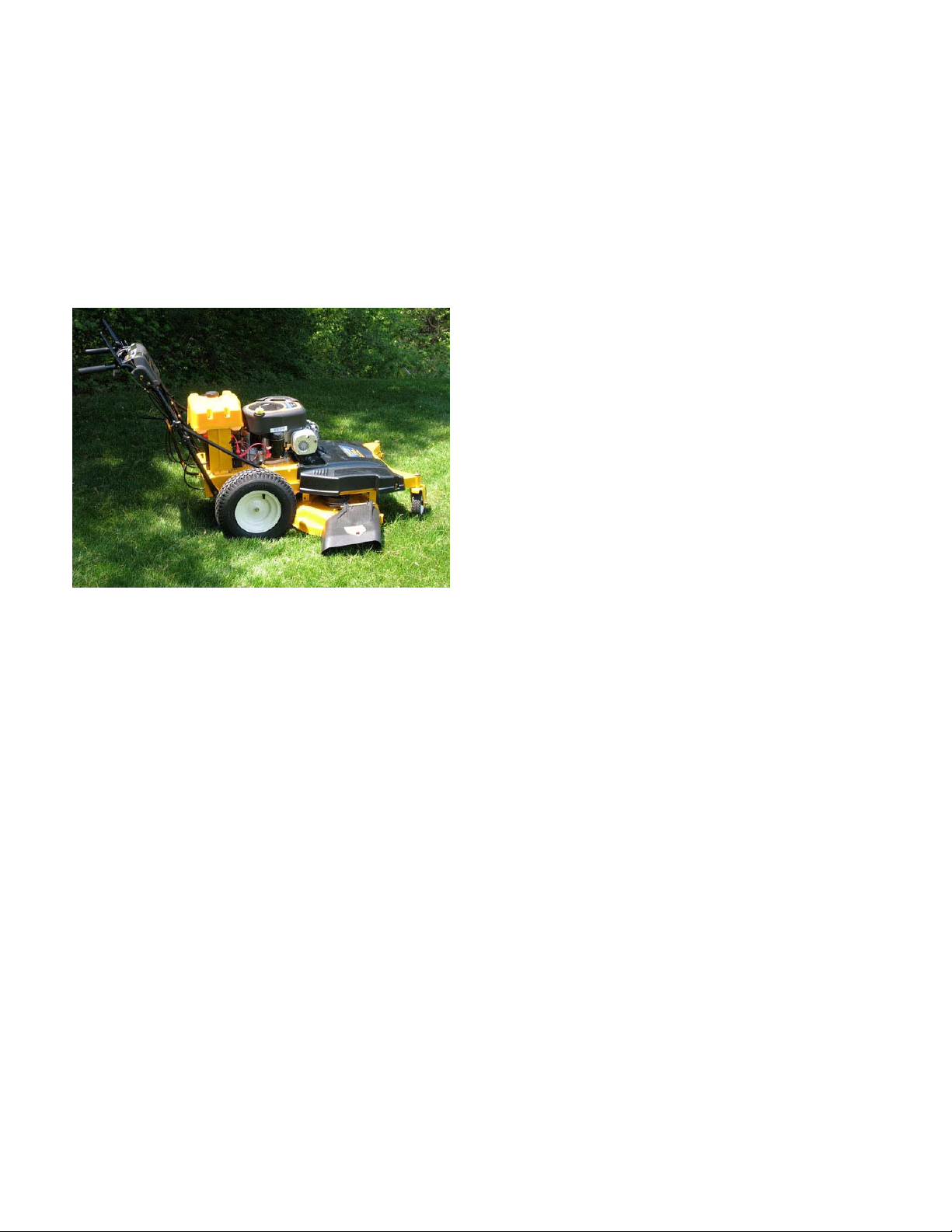
Description of the Mower
The Troy-Bilt 33” wide cut mower was discontinued in
2005. It has since been completely redesigned and
released as a Cub Cadet for the 2007 season.
See Figure 1.1.
Figure 1.1
Some changes and features included on this mower:
• Easier access to the belts.
• Improved blade timing.
• Control rods replaced with cables.
• Controls are more user friendly.
• The mower is 20 lbs lighter.
• Deck Height Control.
• 2 gallon fuel tank.
Disclaimer: The information contained in this Manual is
correct at the time of writing. Both the product and the
information about the product are subject to change
without notice.
Disclaimer: This handbook is intended for use by
trained, professional technicians.
• Common sense in operation and safety is
assumed.
• In no event shall MTD or Cub Cadet be liable for
for poor text interpretation, or poor execution of
the procedures described in the text.
• If the person using this handbook is uncomfortable with any procedures they encounter, they
should seek the help of a qualified technician.
Fasteners
• Most of the fasteners used on the mower are
sized in fractional inches. Some are metric. For
this reason, wrench sizes are frequently identified in the text, and measurem ents are given in
U.S. and metric scales.
• If a fastener has a locking featu re th at has wo rn,
replace the fastener or apply a small amount of
releasable threadlocking compound such as
Loctite® 242 (blue).
• Some fasteners like cotter pins are single-use
items that are not to be reused.
Other fasteners such as lock washers, retaining
rings, and internal cotter pins (hairpin clips) may
be reused if the do not show signs of wear or
damage. This manual leaves that decision to
the judgement of the technician.
• 10.5 horse power Briggs engine. (Horse power
as rated by Briggs and Stratton)
• 33” cutting width.
• 4 speed Peerless Transmission.
• Simplified gear selector.
• Single lever deck height adjustments.
• Timed dual blades.
• Front (grease able) caster wheels for better
maneuverability.
1
Page 5
Chapter 1: Introduction
Assembly
Torque specifications may be noted in the part of the
text that covers assembly, they may also be summarized in tables along with special instructions regarding
locking or lubrication. Whichever method is more
appropriate will be used. In many cases, both will be
used so that the manual is handy as a quick-reference
guide as well as a step-by-step procedure guide that
does not require the user to hunt for information.
The level of assembly instructions provided will be
determined by the complexity and of reassembly, and
by the potential for unsafe conditions to arise from mistakes made in assembl y.
Some instructions may refer t o other parts of the manual for subsidiary procedures. This avoids repeating
the same procedure two or three times in the manual.
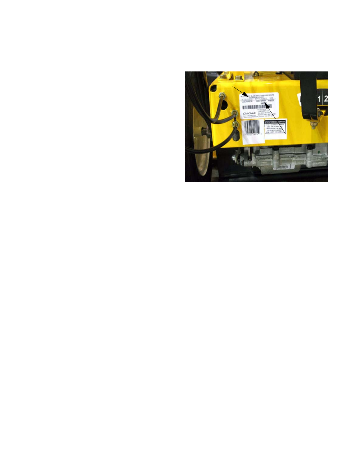
Model and Serial Numbers
The model and serial number tag can is located in the
back of the mower. See Figure 1.2.
Model Number
Serial Number
Figure 1.2
The model number is 12AE764N709.
The model number breaks down as follows:
12.........................self propelled
...A.......................sales level
......E....................type of starter (e = electric)
.........76................deck
.............4N...........engine
..................709.....customer number
The serial number is 11D107B20004.
The serial number breaks down as follows:
1...........................engineering level
.D.........................month of production (D = April)
.....10....................day of the month
.........7..................last digit of the year
...........B................plant it was built in
..............2.............assembly line number
.................0004.....number of unit built
2
Page 6
CHAPTER 2: MAINTENANCE
MAINTENANCE
Cleaning
Maintaining any piece of equipment begins with keeping it clean. Any spills such as fuel or oil should be
wiped off promptly. Use a mild detergent and water to
wash the mower.
NOTE: Do NOT use a pressure washer to clean
the mower. It may cause damage to the electrical components or remove lubrication that is
needed in critical areas.
NOTE: Using polishers like pledge on the plastic
components will affect their finish.
Use the Deck Wash System™ to rinse grass clippings
from the underside of the deck and prevent the build up
of corrosive chemicals caused by decaying vegetation
or fertilizers. It should only be done after the deck has
cooled down. Run the cutting deck for 15 minutes af terwards to dry the deck. After the deck is dry, inject one
squirt of grease in each spindle.
Lubricants
The grease used on this mower should be a high quality lithium based grease.
A high quality light weight oil such as WD 40 or 3-in-1
oil should be applied to all hinge and rotating points
that are not equipped with grease fittings.
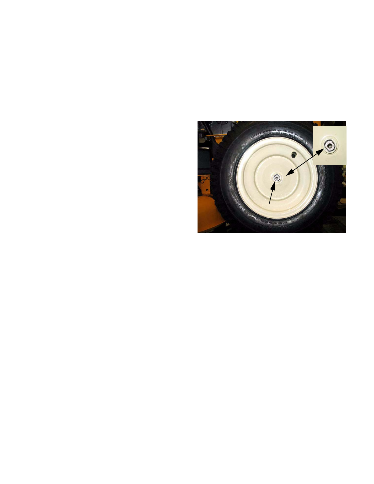
Axle shafts
The rear axle shaft coming from the transmission is a
double-D shaft. As required of all double-D axle shafts,
the wheels should be removed once a year and the
shafts coated with anti-seize. See Figure 2.1.
Double-D
Figure 2.1
NOTE: Failure to remove the wheels once a
year and lubricating the axle shaft will usually
result in the rim rust welding to the axle shaft.
A drop of oil on the steel braid of the cables, where the
enter the cable jacket, will prolong the life of the cables.
3
Page 7
MAINTENANCE
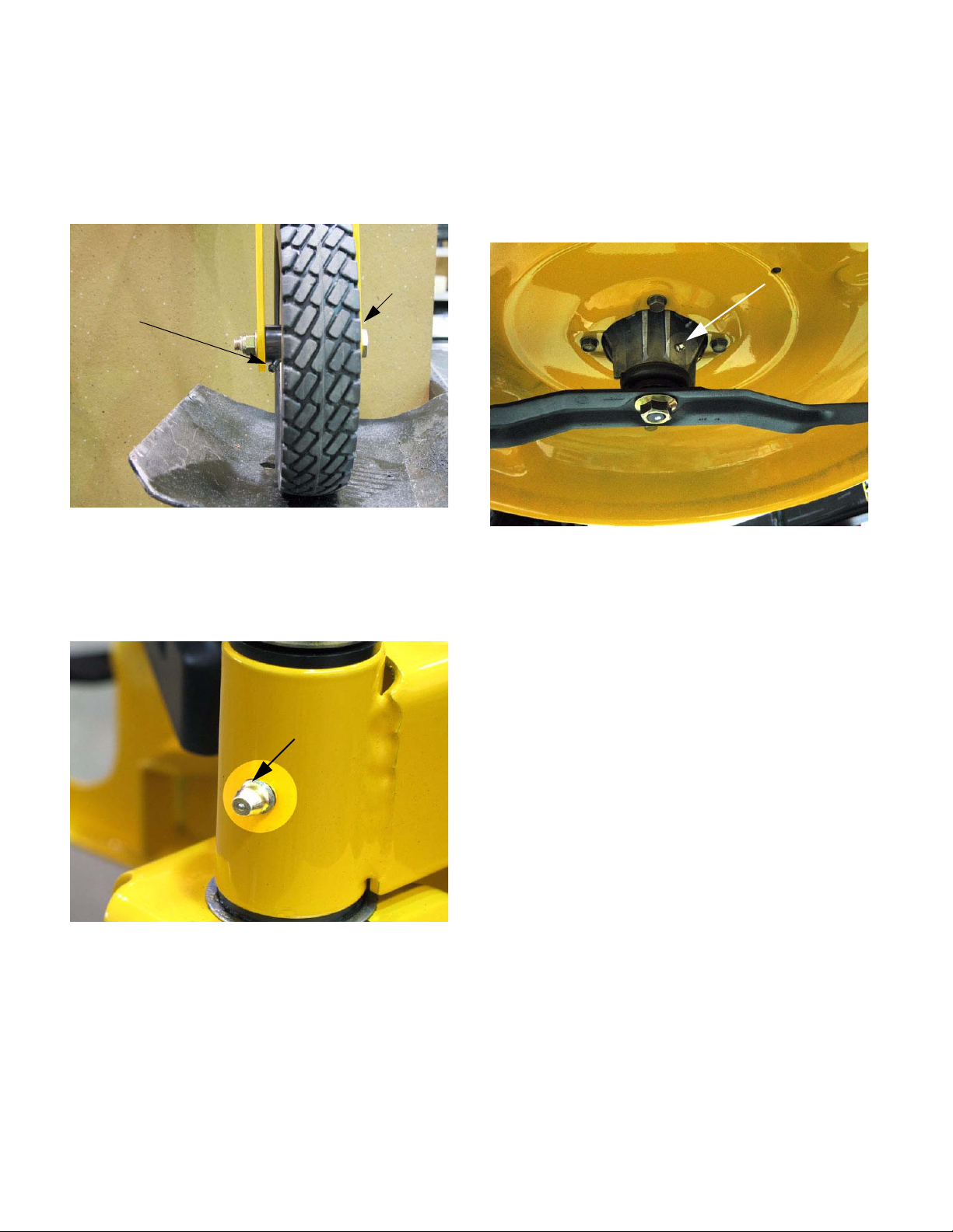
Front casters
The front caster wheels of the mower are equipped
with two grease fittings. Any grease injected into one
side of the wheel will migrate to the other side. A high
quality lithium grease is recommended. See Figure 2.2.
Grease
Grease fitting
Figure 2.2
The front wheel spindles are equipped with grease fittings and should be greased after each season of use
or every 50 hours what ever comes first.
See Figure 2.3.
fitting
Spindles
Both blade spindles are equipped with grease fittings.
The spindles should be greased every 50 hours or at
the end of the mowing season which ever comes first.
See Figure 2.4.
Grease fittings
Figure 2.4
CAUTION: Never put more that one squirt of
grease, per servicing, into a spindle. Putting
more that one squirt of grease into a spindle will
result in the bearings being pressed out of the
spindle housing.
Grease Fitting
Figure 2.3
NOTE: Failure to grease the front wheel spin-
dles could result in poor turning ability.
NOTE: Blades should be checked on a regular
basis for damage or dulling that has occurred
from regular use.
NOTE: Cutting with a dull or bent blade will
greatly reduce the quality of the cut.
NOTE: Replace any blade that is bent, damaged
or worn beyond the normal sharpening range.
CAUTION: If a blade is bent Do NOT try to bend
it back.
4
Page 8
MAINTENANCE
Fasteners
Check all fasteners annually for any signs of lo osening
or damage.
Excessive vIbration is a primary cause of fatigue failures. Vibration can loosen fasteners and fatigue met al.
Transmission
The 4 speed peerless transmission has 16 oz.(454 ml)
of 80w-90 gear lube.
The gear lube should not need to be changed unless it
has become contaminated.
Engine
For maintenance and repair procedures, cont act the
engine manufacturer.
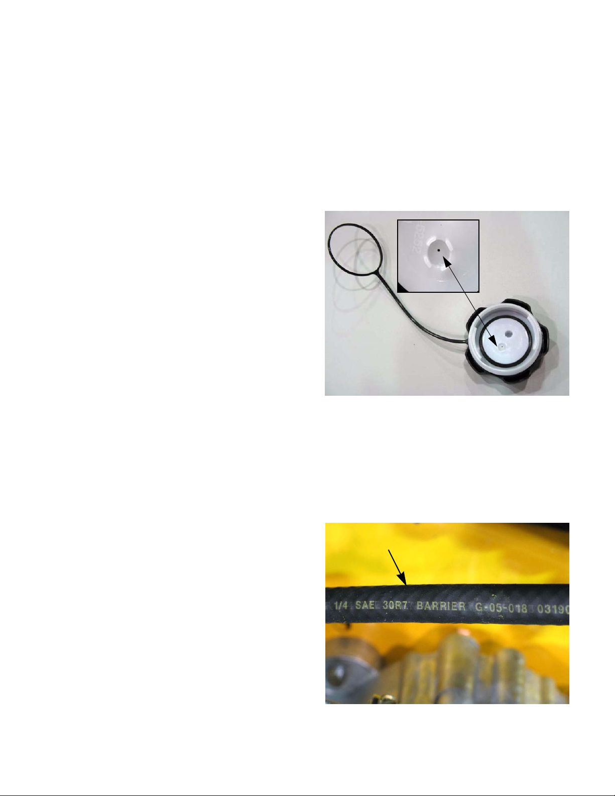
Emissions
In order to meet the new EPA regulations, there has
been some changes to the fuel system. The fuel tank
is blow moulded and composed of a high density polymer. The fuel cap has a ratchet feature that will prevent
the end user from over tightening it.
The fuel cap is vented through a small hole located in
the top of the inner fuel cap. The air is drawn in thro ugh
the gap between the inner and outer fuel cap shells.
See Figure 2.5.
Vent
Figure 2.5
Fuel line
IMPORTANT: This mower uses the Green-bar
low permeation fuel line that is mandated by the
EP A. It min imizes the gasolin e fumes th at percolate into the atmosphere through the fuel line.
Use the same type of line when replacing the
fuel line. See Figure 2.6.
Fuel line
Figure 2.6
5
Page 9
CHAPTER 3: DRIVE SYSTEM
Drive system
A single belt is used to transfer power from the engine
crankshaft to the input shaft of the transaxle. The left
side control handle and cable operate a tensioner pulley that tightens the belt to engage the drive system
and loosens the belt to de-clutch the drive system.
Gear selection is done by a simple extension arm that
connects to the shift shaft of the transfer case.
Transaxle
The Transaxle is a peerless HMST-204-754, with 4 forward speeds, Neutral and 1 reverse.
The transaxle contains 16 fl oz (454 mL) of 80w90 gear
lube. It should not need to be changed, unless it
becomes contaminated or is drained to disassemble
the transaxle.
Complete service instructions can be found in the
Tecumseh/Peerless Motion Drive Systems handbook,
form #691218.
Drive Belt
To remove/replace the drive belt:
1. Remove the deck as described in the section on
the Drive Engagement Cable.
3. Remove the belt guide that is near the idler pulley using a pair of 7/16” wrenches.
See Figure 3.2.
Belt guide
Figure 3.2
4. Loosen the drive belt tension pulley two 9/16”
wrenches. See Figure 3.3.
2. Remove the belt guide that is near t he transm ission pulley using two 7/16” wrenches.
See Figure 3.1.
Belt keeper guide
Figure 3.1
9/16 Wrench
Figure 3.3
6
Page 10

Drive system
T
5. Slip the belt past the belt guide and work the belt
off of the remaining pulleys.
IMPORTANT: Before installing a new belt, it
must be turned inside out to route the belt properly.
6. Install the belt following the above steps in
reverse order. For belt routing See Figure 3.4.
ransaxle
Pulley
Engine Pulley
Drive
belt
Figure 3.4
Drive Cable
A cable is used to pull the idler pulley to engage the
transmission driving the wheels. This puts tension on
the drive belt allowing it to turn the transmission pulley.
This cable is not adjustable.
To replace the drive cable:
1. Unhook the top Z-fitting from the drive engagement lever. See Figure 3.5.
Drive engagement cable
Drive cable
7. Install the drive cable by following the above
steps in reverse order.
8. Test run the mower before returning it to service.
Figure 3.5
2. Remove the cable from the cable bracket on the
handle bar using two 1/2” wrenches. Remove
the nut then slide the cable out through the slot
in the bracket. See Figure 3.6.
Drive cable
Figure 3.6
7
Page 11

Drive system
3. Remove the deck by following the steps
described in Chapter 4: Deck and lift shaft.
4. Unhook the drive cable from the idler bracket.
See Figure 3.7.
Drive cable
Figure 3.7
5. Remove the cable from the frame by using two
1/2” wrenches to loosen the jam nuts.
See Figure 3.8.
Brakes
The brake is released by squeezing either or both
levers. The handle on the left hand side will release the
brake when the drive control lever is engaged.
See Figure 3.9.
Figure 3.9
The handle on the right side is the deck engagement
lever. It will release the brake when it is pressed down,
allowing the mower to cut without the transmission
being engaged. See Figure 3.10.
Drive
cable
Figure 3.8
6. Install the drive cable by following the above
steps in reverse order.
7. Test run the mower in a safe area before returning to service.
Figure 3.10
As a safety feature, when both control levers are
released the brakes will be applied.
NOTE: Because the brake is on an intermed iate
shaft in the transaxle, there will still be differential action. The mower will pivot when the brakes
are applied, but it will not roll,
8
Page 12

Drive system
The two cable design allows the operator to mow without engaging the traction (wheel) drive. This is a handy
feature for mowing in tight areas where maneuverability is needed. The traction drive can also be engaged
independently of the deck. This is a handy feature for
transport.
The shift rod can be easily moved with a side to side
push from the users hand. To shift from one gear to
another the mower needs to be completely stopped. To
shift the mower into reverse the shifter has to be lift ed
and slid to the left. This prevents the mower from being
shifted into reverse accidently.
The brake system used in the Wide Area Mower is
engaged at rest. When either the deck or drive control
is squeezed the brake cable pulls back on the brake
lever on the transmission and disengages the brake.
The brake cables are the lower cables on the engagement handle or closest to the pivot point. See Figure
3.11.
Brake adjustment
1. Raise the rear of the mower at least 18” off the
ground.
2. Safely support mower with jack stands.
3. Squeeze either the deck or traction drive control
to release the brake.
4. Confirm that the caliper is properly assembled
and is in good working condition.
5. Use a spring clamp or rope to hold the handle
down. See Figure 3.12.
Brake Cable
Figure 3.11
Pivot
Point
Figure 3.12
6. Insert a .010” -.015” (.254mm -.381mm) feeler
gauge between the brake puck and the brake
disk. See Figure 3.13.
.010-.015
(.254mm.381mm)
1/2” wrench
Figure 3.13
9
Page 13

Drive system
7. If the brake needs to be adjusted, tighten or
loosen the adjustment nut with a 1/2” wrench,
See Figure 3.13.
NOTE: If the brake is set too tight the mower will
drag and not drive smoothly.
NOTE: If the mower doesn’t stop immediately
after both control levers are release d the adjust ment may be to loose.
Brake caliper
1. Raise the rear of the mower at least 18” off the
ground.
2. Safely support mower with jack stands.
3. Remove the spring that maintains tension on the
brake. It is attached to the brake engagement
lever and to a spring retainer rod.
See Figure 3.14.
Extension Spring
Brake
Lever
Spring Retaining Rod
Figure 3.14
4. Disconnect the brake cables by unhooking the
loop link coupler. See Figure 3.15.
Brake cables
Return spring
Figure 3.15
loop
link coupler
10
Page 14

Drive system
5. Remove the two caliper mounting bolts.
See Figure 3.16.
Figure 3.16
6. Remove the caliper and outboard brake puck.
7. Slide the brake disc off the splined shaft to
expose the inboard brake pad for inspection. See
Figure 3.17.
8. Inspect the brake yoke for signs of corrosion that
may prevent proper movement of pins through
the yoke. See Figure 3.18.
Actuator Pins
Brake Pad
Plate
Figure 3.18
NOTE: The two screws that fasten the brake
yoke have a patch of loctite. Replace them or
apply a small amount of releasable threadlocking compound such as Loctite® 242 (blue)
Adjustment
Screw
Brake Yoke
Front Brake
Pad
Brake Disk
Inboard Brake
Pad
Figure 3.17
NOTE: A small amount of good quality lithium
grease should be applied to the splines. Take
care not to get any grease on the brake pads or
the friction surfaces of the rotor.
.
11
Page 15

Drive system
Brake cables
To replace the cables:
NOTE: These cables are not adjustable.
1. Loosen the lock nuts located on the cable brackets and slide it up the cable. The bracket is
located on the handle bar beneath the dash
panel on both sides of the handle bars.
See Figure 3.19.
Figure 3.19
3. The cable will now be loose enough to slip the zfitting from the handle. See Figure 3.21.
Deck engagement cable
Brake
Cable
Figure 3.21
4. The brake cables are joined together on a loop
link coupler located under the frame on the left
hand side. See Figure 3.22.
Brake cable
Eyelets
2. Pull down slightly on the cable jacket. This will
allow the cable to slide out of the slotted bracket.
See Figure 3.20.
Figure 3.20
Loop Link
Coupler
Figure 3.22
12
Page 16

Drive system
5. Loosen the connecting nut of the loop link coupler with a 3/8” wrench to free the eyelets on the
brake cable. See Figure 3.23.
3/8”
wrench
Figure 3.23
6. Loosen the two lock nuts at the lower fram e to
free the cable from the frame. Use a pair of ½”
wrenches. See Figure 3.24.
7. Pull each cable out and down to free the cable
from the frame. The cables can be pulled 1 at a
time through the lowest hole in the punch out.
See Figure 3.25.
Figure 3.25
NOTE: To remove the upper cable, it is neces-
sary to remove the lower cable.
1/2” wrenches
Figure 3.24
8. Install the brake cables following the above
steps in reverse order.
9. Test run the mower in a safe area before returning to service.
13
Page 17

Drive system
Transmission Removal and replacement
1. Loosen wheel bolts using a 1/2” wrench.
2. LIft and safely support mower so that the wheels
are at least 18” off the ground.
3. Remove both rear wheels . See Figure 3.26.
1/2” hex bolt
Figure 3.26
6. Detach the lower shift rod from the upper shift
rod using a pair of 1/2” wrenches.
See Figure 3.28.
1/2” Wrenches
Figure 3.28
7. Detach the brake return spring from the spring
tension rod. Use a length of starter rope or spring
puller. See Figure 3.29.
4. Remove the traction drive belt as described on
the tractor drive belt section.
5. Detach the brake cables from the loop link coupler. See Figure 3.27.
3/8”
Wrench
Figure 3.27
Figure 3.29
14
Page 18

Drive system
8. Remove the hairpin clip that fastens the spring
tension rod to the transmission. See Figure 3.30.
Hairpin clip
Figure 3.30
9. Place a support under the transmission to prevent it from falling.
10. Remove the four transmission mounting bolts.
Using a pair of 1/2” wrenches. See Figure 3.31.
11. Lower the transmission and tilt it forward to
guide it out from under the frame.
12. When the transmission is out of the mower
remove the lower shift rod, spring retention rod,
and extension spring. Install them on the new
Transmission.
NOTE: Bench test the transmission prior to
replacing or shipping to the manufacturer for
warranty. To bench test a transmission with the
transmission out of the mower: move the gear
shifter to each speed position and rotate the
transmission pulley to verify that the transmission drives or fails to drive.
13. Remove the transmission pulley.
NOTE: When reinstalling the transmission pul-
ley, tighten to a torque of 300 to 400 in lbs (34 45 Nm). See Figure 3.32.
Figure 3.31
Figure 3.32
14. Install by following the above steps in reverse
order.
15. Test run the mower before returning it to service.
15
Page 19

CUTTING DECK AND LIFT SHAFT
CHAPTER 4: CUTTING DECK AND LIFT SHAFT
Deck removal
1. Take the deck cover off by removing the three
self tapping screws with a 3/8” wrench.
See Figure 4.1.
Self Tapping Screws
Figure 4.1
NOTE: Early 2007 production used nuts and
bolts to fasten the belt cover on.
5. Remove the four hairpin clips in the deck lif t links
and slide the deck to the left to clear the hanging
pins on the lift links. See Figure 4.3.
4 hairpin locations
Figure 4.3
6. Remove the belt guide with a pair of 5/16”
wrenches. See Figure 4.4.
2. Slide the cover off of the mower.
3. Lower the deck to the lowest cutting height.
4. Release the tension on the engagement pulley.
Disconnect the spring end of the deck engagement cable from the Idler bracket.
See Figure 4.2.
Figure 4.2
5/16” nuts
Figure 4.4
7. Remove the deck belt from the engine pulley.
8. Slide the deck out from under the mower.
9. Install the deck by following the above steps in
reverse order.
10
Page 20

CUTTING DECK AND LIFT SHAFT
Cleaning the deck
Clean debris off of the deck every time the deck cover
is removed. It is routine maintenance that will make the
deck easier to work on and prolong the life of the deck
and spindles.
DANGER: Debris build up on the mower deck is
an unsafe condition. The debris traps heat in the
spindles causing damage to the spindle bearings. Debris around the belt can over-heat.
To clean the deck while it is removed:
1. Blow all the debris off of the top of the deck
using compressed air regulated to about 35psi
(2.5 bar).
2. Scrape off the debris build up from the under
side of the deck using a plastic scraper.
NOTE: Applying a light coating of oil to the
underside of the deck after scraping it clean will
help prevent rusting of the deck and help keep
the debris from building up on the underside of
the deck.
Blades
The condition of the blades will greatly effect the quality
of the cut.
The blades should be sharpened and balanced after
every five acres, depending on local conditions. A dull
blade tears the grass instead of cutting it. Torn grass
blades leaves a rough look and makes the grass vulnerable to diseases.
Blades need to be examined for damage before sharpening. Blades must be balanced after sharpening to
reduce the vibrations felt from the deck.
Bent blades are a sign of a blade impact. The blades
must be replaced and the spindles inspected for damaged timing belt, pulley, bent shafts and cracked housings if a bent blade is found.
Synchronized blades and a high vacuum deck shell
design give an exceptionally good cut using OEM
blades.
The cutting deck on this mower is mounted with a slight
rake, meaning that the front of the deck is a 1/4” - 3/8”
lower than the rear of the de ck. This is very important
to get the proper air flow in the deck so that the blades
can make the grass blades stand up to get cut.
Air flow in the cutting deck is generated by the spin ning
blades. If the blades are mounted upside down, the air
flow will be reversed pushing the grass down instead of
standing up.
NOTE: Blades have the part number and the
word patent stamped on the bottom of the blade.
Blades that are mounted upside down, increase
the risk of impacting an object. See Figure 4.5.
Stampings
11
Figure 4.5
Page 21

CUTTING DECK AND LIFT SHAFT
Blade removal
1. Remove the deck as described in the previous
section of this chapter or lift the tractor using a
professional grade lift.
2. Remove the blade nuts using an impact wrench
and a 15/16” socket. See Figure 4.6.
Blade nut
Figure 4.6
5. Install the blade by following the above steps in
reverse order. Tighten the blade nut to a torque
of 70 - 90 ft-lbs ( 95 - 122 Nm).
NOTE: The blades have a star center. The star
must seat on the raised star on the bottom of the
spindle shaft with the fins of the blade pointing to
the deck. If there is damage to the raised star of
the spindle shaft, the spindle must be replaced.
See Figure 4.7.
Star center
CAUTION: Use care around the blade while
removing or tightening the nut. The blade can
spin and cause an injury to the technician.
3. Remove the blade.
4. When sharpening the blades:
• To properly sharpen the cutting blades, remove
equal amounts of metal from both ends of the
blades along the cutting edges, parallel to the
trailing edge, at a 25° to 30° angle. Sharpen the
top edge only.
IMPORTANT: If the cutting edge of the blade
has already been sharpened to within 1 5/8”
from the edge, or if any metal separation is
present, replace the blades with new ones.
• It is important that each end of the cutting blade
edge be ground equally to maintain proper blade
balance.
CAUTION: A poorly balanced blade will cause
excessive vibration and may cause damage to
the mower and result in personal injury.
Figure 4.7
• The blade can be tested by using a blade balancer. Grind metal from the heavy side until it
balances evenly.
12
Page 22

CUTTING DECK AND LIFT SHAFT
Spindles
The spindles are a complete unit. The only replaceable
parts are the pulleys. The spindles are equipped with a
grease fitting that should get one squirt of grease after
every use of the deck wash system or every 10 hours
of use.
NOTE: Never put more than one squirt of grease
in a spindle. Putting more grease in the spin dle
will push the bearing out of the spindle housing,
ruining the spindle.
To replace a pulley:
1. Remove the deck as described at the beginning
of this chapter.
2. Remove the belts by following the steps
described later in this chapter. See Figure 4.8.
Pulley nuts
To replace a spindle:
1. Remove the deck as described at the beginning
of this chapter.
2. Remove the blade following the steps described
in the previous section of this chapter.
3. Remove the belts by following the steps
described later in this chapter.
4. Remove the four screws fastening the spindle to
the deck. See Figure 4.9.
Remove these
screws
PTO belt
Timing belt
Figure 4.8
3. Remove the blade following the steps described
in the previous section of this chapter.
4. Remove the pulley nut using an impact wrench
with a 15/16” socket. See Figure 4.8.
5. Install the spindle pulleys by following the above
steps in reverse order.
6. Test run the tractor before returning to service.
Figure 4.9
5. Lift the spindle out of the deck shell.
6. Install the spindle by following the above steps in
reverse order.
NOTE: The four spindle bolts are self tapping
bolts. The new spindle housing will not have
threads in it.
NOTE: Tighten the spindle bolts to a torque of
200 - 300 in-lbs (23 - 34 Nm).
13
Page 23

CUTTING DECK AND LIFT SHAFT
PTO belt
The function of the PTO belt is to transfer the mechanical force from the engine to the blades. The belt faces
a lot of different forces.
• Clutching and de-clutching
• Heat from bending or deformation.
• The friction of the belt against the pulleys creates heat. This heat softens the belt which weakens it.
• When a blade impacts an object like a rock or a
tree root, the belt is subjected to an shock load.
• The belt has rubber in it. as the rubber ages, it
becomes brittle making it weaker.
NOTE: A damaged belt can cause the deck to
vibrate when the deck is engaged. The vibration
can be bad enough to simulate an engine or
blade issue.
NOTE: Not all belt damage is visible. Broken
cords inside the belt are not visible to the naked
eye, but can cause vibration issues and greatly
reduce the life of the belt.
CAUTION: Cub Cadet belts are design to fit our
equipment and are not standard lengths. Use of
a non-OEM belt may prevent the mowing deck
from working properly.
2. Slide the cover off of the mower.
3. Release the tension on the engagement pulley.
Disconnect the spring end of the deck engagement cable from the Idler bracket.
See Figure 4.11.
Figure 4.11
4. Loosen both idler pulleys enough to slip the belt
out between the idler pulleys and the belt guides
using a pair of 9/16” wrenches See Figure 4.12.
To service the deck belt:
1. Take the deck cover off by removing the three
self tapping screws with a 3/8” wrench.
See Figure 4.10.
self tapping screws
Figure 4.10
NOTE: Earlier 2007 production may have nuts
and bolts securing the belt cover to the frame.
Belt Guides
Idler Pulley
Figure 4.12
.
14
Page 24

CUTTING DECK AND LIFT SHAFT
5. Remove the belt guide by the engine pulley with
a pair of 3/8 wrenches. See Figure 4.13.
Remove this
nut
Figure 4.13
6. Slide the belt off of the pulleys.
7. Discard the old belt.
8. Install a new deck belt by following the steps
above in reverse order.
Deck Timing Belt
To service the deck timing belt:
1. Take the deck cover off by removing the three
self tapping screws. See Figure 4.14.
three self tapping screws
Figure 4.14
NOTE: Nuts and bolts were used in early 2007
production to fasten the belt cover.
9. Test run the mowe r be fo re retur nin g to serv ice .
2. Slide the cover off of the mower.
3. Loosen both idler pulleys enough to slip the belt
out between the idler pulleys and the belt guides
using a pair of 9/16” wrenches. See Figure 4.15.
Figure 4.15
15
Page 25

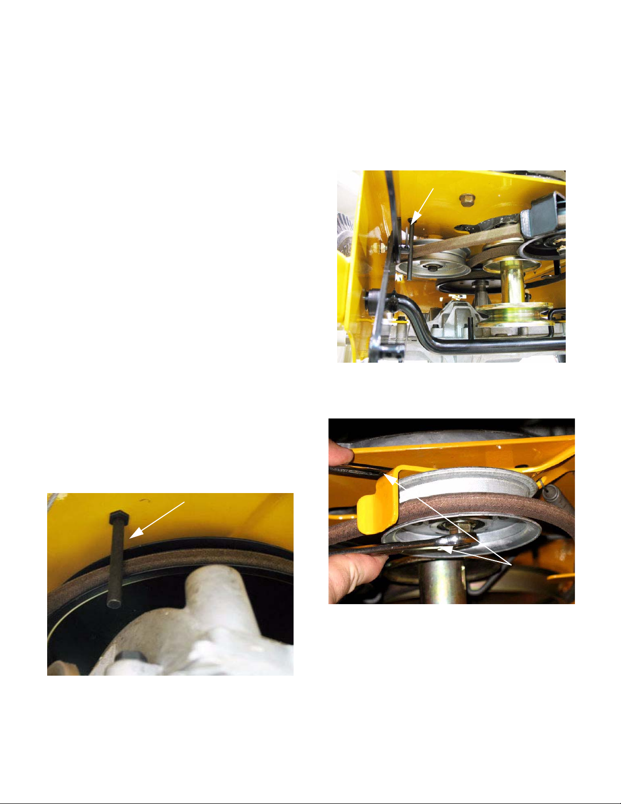
CUTTING DECK AND LIFT SHAFT
4. Slide the belt off of the left side spindle.
5. Back the jam nut on the idler stop bolt to the
head of the bolt. See Figure 4.16.
Idler Stop Bolt
Figure 4.16
6. Insert a 3/8” ratchet or breaker bar into the
square hole in the idler bracket. Swing the idler
pulley away from the timing belt, pushing in the
idler stop bolt, using the ratchet for leverage.
See Figure 4.17.
7. With the tension relieved slip the timing belt off
of the pulleys.
8. To install the timing belt turn the blades 90
apart. See Figure 4.18.
o
90
Figure 4.18
NOTE: Failure to time the blades will result in
the blades hitting each other.
9. The timing marks will line up with the blades and
would need to be 90
o
apart. See Figure 4.19.
o
3/8” breaker bar
Figure 4.17
Blade
Timing Marks
Figure 4.19
NOTE: The timing marks on the blade pulleys
have been shown in white for clarity.
16
Page 26

CUTTING DECK AND LIFT SHAFT
10. Slide the timing belt over the spindles.
11 . Swing the idler pulley away from the belt using a
3/8” ratchet for leverage.
12. Slip the timing belt behind the idler pulley.
See Figure 4.20.
Idler Stop
Bolt
Figure 4.20
Test run the mower befo re ret urnin g to ser vice .
Deck engagement (PTO) cable
To service the PTO cable:
1. Unhook the top Z-fitting from the blade engagement lever. See Figure 4.22.
PTO cable
Figure 4.22
NOTE: The spring is applying enough force to
hold tension on the idler. The idler stop bolt is
there to prevent the idler from springing back
during a blade impact. This prevents the blades
from jumping time.
13. Tighten the jam nut on the idler stop bolt until
there is a .040” (1 mm) maximum gap between
the idler stop bolt and the idler bracket.
See Figure 4.21.
9/16”
Nuts
Maximum gap
.040
2. Remove the cable from the cable bracket on the
handle bar using two 1/2” wrenches to remove
the nut then slide the cable out through the slot
in the bracket. See Figure 4.23.
PTO cable
Figure 4.23
Figure 4.21
14. Reinstall the PTO belt.
15. Install the deck cover.
17
Page 27

CUTTING DECK AND LIFT SHAFT
3. Take the deck cover off by removing the three
nuts and bolts. See Figure 4.24.
NOTE: depending on production date the nuts
and bolts may have been replaced by self tapping screws.
Remove these
bolts or screws
Figure 4.24
4. Slide the cover off of the mower.
6. Remove the cable from the frame using two 1/2”
wrenches. See Figure 4.26.
Blade cable
Figure 4.26
7. Install the PTO cable by following the above
steps in reverse order.
8. Test run the mower before returning to service.
5. Unhook the blade cable from the idler bracket.
See Figure 4.25.
PTO
cable
Figure 4.25
18
Page 28

CUTTING DECK AND LIFT SHAFT
Leveling the deck
For the best quality cut, the deck must be level side to
side and the front of the deck should be 1/4” - 3/8”
lower than the rear of the deck.
Side to Side Leveling
1. With the mower parked on a firm, level surface,
move the deck to the mid height position using
the deck lift lever. Rotate one blade so that it is
perpendicular with the mower frame.
2. Measure the distance from the blade tip to the
ground.
3. Repeat steps 1 and 2 on the other side
4. Both measurements taken should be equal. If
they are not, note whether the left side of the
deck is lower or higher and proceed to the next
step.
NOTE: U se of Cub Cadet deck lev eling gauge,
part number 490-900-0041, will make measuring
the blade tip height easier. See Figure 4.27.
Deck lift shaft and lever
To remove the deck lift shaft:
1. Remove belt cover and deck by following the
steps previously described..
2. Remove the hairpin clips from the bracket that
links the front and rear lift rods. See Figure 4.28.
Hair Pin
Clips
Figure 4.27
5. There are no adjustments for leveling the deck
on this mower. Minor adjustments to level the
deck can be made by altering th e air p ress ure in
the tires. If the adjustment requires more than a
5psi difference between tires, something on the
mower is bent.
Figure 4.28
3. Remove the deck height lever with a 1/2”
wrench. See Figure 4.29.
1/2”
wrench
Figure 4.29
19
Page 29

NOTE: The deck adjustment lever is divided into
three (3) parts, the adjustment handle and two
(2) lever pivot brackets. See Figure 4.30.
Adjustment handle
Lever Pivot
Brackets
Figure 4.30
CUTTING DECK AND LIFT SHAFT
4. Remove the split bushing from the rear lift shaft.
See Figure 4.31.
Split bushing
Figure 4.31
5. Work the shaft out of the frame.
6. Repeat steps 4 and 5 on the front lift shaft.
7. Reinstall the lift shaft and lift lever by following
the above steps in reverse order.
Lift shaft
8. Test run the mowe r be fo re retur nin g to serv ice .
20
 Loading...