

Page 1

Page 2
Page 3
(t) *C~~~E!!EJ
To reduce the potential for any injury, comply with the following safety instructions. Failure to comply
with the instructions may result in personal injury.
SAFE OPERATION PRACTICES FOR RIDING VEHICLES
1. Read this owner's manual carefully in its en- 16. Disengage power to attachment(s) and stop
tirety before attempting to assemble or engine before making any repairs or adoperate this unit. Keep this manual in a safe justments. Disconnect the spark plug wire
place for future and regular reference and for and keep the wire away from the plug to preordering replacement parts. vent accidental starting.
2. This unit is a precision piece of power equip- 17. Before attempting to unclog the mower or
ment, not a plaything. Therefore exercise ex- discharge chute, stop the engine. The mower
treme caution at all times. blade(s) may continue to rotate for a few
3. Know the controls and how to stop quickly- seconds after the engine is shut off.
READ THIS OWNER'S MANUAL. Therefore, be sure the blade(s) have stopped
4. Do not allow children to operate vehicle. Do completely. Disconnect the spark plug wire
not allow adults to operate it without proper and keep the wire away from the plug to preinstruction. Only persons well acquainted vent accidental starting.
with these rules of safe operation should be 18. Disengage power to attachment(s) when
allowed to use your mower. transporting or not in use.
5. ~o one shO';Jld op.erate th.is u,nit whil~ int<?x- 19. Take all possible precautions when leaving
Icated or while takl~g medication that Impairs vehicle unattended such as disengaging
the senses or reactions. power-take-off, lowering attachments, shift-
6. Wear ~t~rdy, rough-soled yvork shoe~ and ing into neutral, setting parking brake, stopclose-fitting. slacks a.nd shirts to avoid en- ping engine and removing key.
tanglement In the moving parts. Never operate .
a unit in bare feet, sandals, or sneakers. 20. Do .not stop or. start suddenly when going
7. To prevent injury, do not carry passengers or uphill or dow.nhili. Mow up and down face of
give rides. Keep children, pets and by- steep slop~s, ~e~er. across the face. ~se exstanders out of the area while mowing. Only treme cautlo~ If .It IS necessary to drive the
the operator should ride on the unit and only trac.tor ~p an Incline or back the tractor down
ride in the seat an Incline because the front of the tractor
8. Check overhea'd clearance carefully before could lift and ra~idly !Iip over backward which
driving under power lines, guy wires, bridges could cause serious Injury.
or low hanging tree branches, before entering 21. Reduce speed on slopes and in sharp turns to
or leaving buildings, or in any other situation prevent tipping or loss of control. Always
where the operator may be struck or pulled keep the tractor in gear when going down
from the unit, which could result in serious in- steep hills to take advantage of engine brak-
jury. ing action.
9. To maintain control of the unit and reduce the 22. Stay alert for holes in terrain and other hidden
possibility of upset or collision, operate the hazards.
tractor .smoothly. Avoid erratic operation and 23. Use care when pulling loads or using heavy
excessive speed.. equipment.10.
Keep the ':lrea of operation .clear of all per- A. Use only approved drawbar hitch points.
sons, pa~tlcularly small ch~ldren a.n~ .pets. B. Limit loads to those you can safely control.
Stop engine when they are In the vIcinity. of C. Do not turn sharply. Use care when backyour mower. Although the area of oP.eratlon ing.
~hould be comple,tely cleared of foreign ob- D. Use counterweight(s) or wheel weights
jects, a small object ~ay have been over. when suggested in owner's manual.
looked and could be accidently thrown by the " .
mower in any direction and cause injury. 24. Watch out for traffic when crossing or near
11. Clear work area of objects which might be roadways.
picked up and thrown by the mower in any 25. When using any a~tachments, never direct dis-
direction and cause injury. charge of material toward bystanders nor
12. Stop the blade(s) when crossing gravel drives, allow anyone near vehicle while in operation.
walks or roads. 26. Handle gasoline with care. It is highly flam-13.
Disengage all attachment clutches and shift mable.
into neutral before attempting to start engine. A. Use approved gasoline container.
14. Disengage power to attachment(s) and stop B. Never remove cap or add gasoline to a runengine before leaving operating position. ning or hot engine or fill fuel tank indoors.
15. Do not put hands or feet near or under rotating Wipe up spilled gasoline.
parts. Keep clear of the discharge opening at C. Open doors if engine is run in garage. Ex-
all times as the rotating blade(s) can cause in- haust fumes are dangerous. Do not run
jury. engine indoors.
3
Page 4
(2) Never make a cutting height adjustment
while engine is running if operator must
dismount to do so.
(3) Shut the engine off and wait until the
blade comes to a complete stop before
removing the grass catcher.
(4) Check blade mounting bolts for proper
tightness at frequent intervals.
34. Check grass catcher bags frequently for wear
or deterioration. For safety protection, replace
only with new bag meeting original equipment
specifications.35.
Look behind to make sure the area is clear
before placing the transmission in reverse
and continue looking behind while backing
up. Disengage blades before shifting into
reverse and backing up.36.
This unit should not be driven up a ramp onto
a trailer or truck under power, because the
unit could tip over, causing serious personal
injury. The unit must be pushed manually to
load properly.
27. Keep the vehicle and attachments in good
operating condition, and keep safety devices
in place. Use guards as instructed in
operator's manual.
28. Keep all nuts, bolts, and screws tight to be
sure the equipment is in safe working condi-
tion.
29. Never store the equipment with gasoline in
the tank inside a building where fumes may
reach an open flame or spark. Allow engine to
cool before storing in any enclosure.
30. To reduce fire hazard, keep engine free of
grass, leaves or excessive grease.
31. The vehicle and attachments should be
stopped and inspected for damage after striking a foreign object. The damage should be
repaired before restarting and operating the
equipment.
32. Do not change the engine governor settings
or overspeed the engine.33.
When using the vehicle with mower, proceed
as follows:
(1) Mow only in daylight or in good artificial
light.
4
Page 5
The Owner
recommended operation and maintenance pro.
cedures are followed.
To obtain top performance and assure economical
operation the tractor should be inspected,
depending on its use, periodically, or at least once
a year, by your authorized dealer.
When in need of parts, always specify the model,
chassis, and engine serial numbers, including the
prefix and suffix letters. Write these serial
numbers in the space provided on this page.
Should you have difficulties with the unit consult
your authorized dealer. UNDER NO CIRCUM.
STANCES SHOULD YOU AnEMPT TO SERVICE
THESE UNITS YOURSELF. Only your dealer is
authorized to repair or replace units on this drive
under the terms of the warranty. Should you
desire additional information not found in this
manual, contact your authorized Cub Cadetdealer.
Assembled in this manual are operation, lubrica-tion,
and maintenance instructions for the Cub
Cadet 1282, 682 and 782 Tractors. The material has
been prepared in detail to help you better understand the correct care and efficient operation of
your tractor. Before you operate the tractor, study
this manual carefully. Additional copies may be
ordered from your dealer at a nominal price.
Your local authorized dealer is interested in the
performance you receive from your tractor. He has
factory-trained servicemen, informed in the latest
method of servicing tractors, modern tools, and
original-equipment service parts which assure
proper fit and good performance.The
Cub Cadet 1282,682 and 782 Tractors have a
hydrostatic drive. It is the best hydrostatic drive
unit available and will require minimum service if
NUMBER LOCATION
Chassis Serial Number
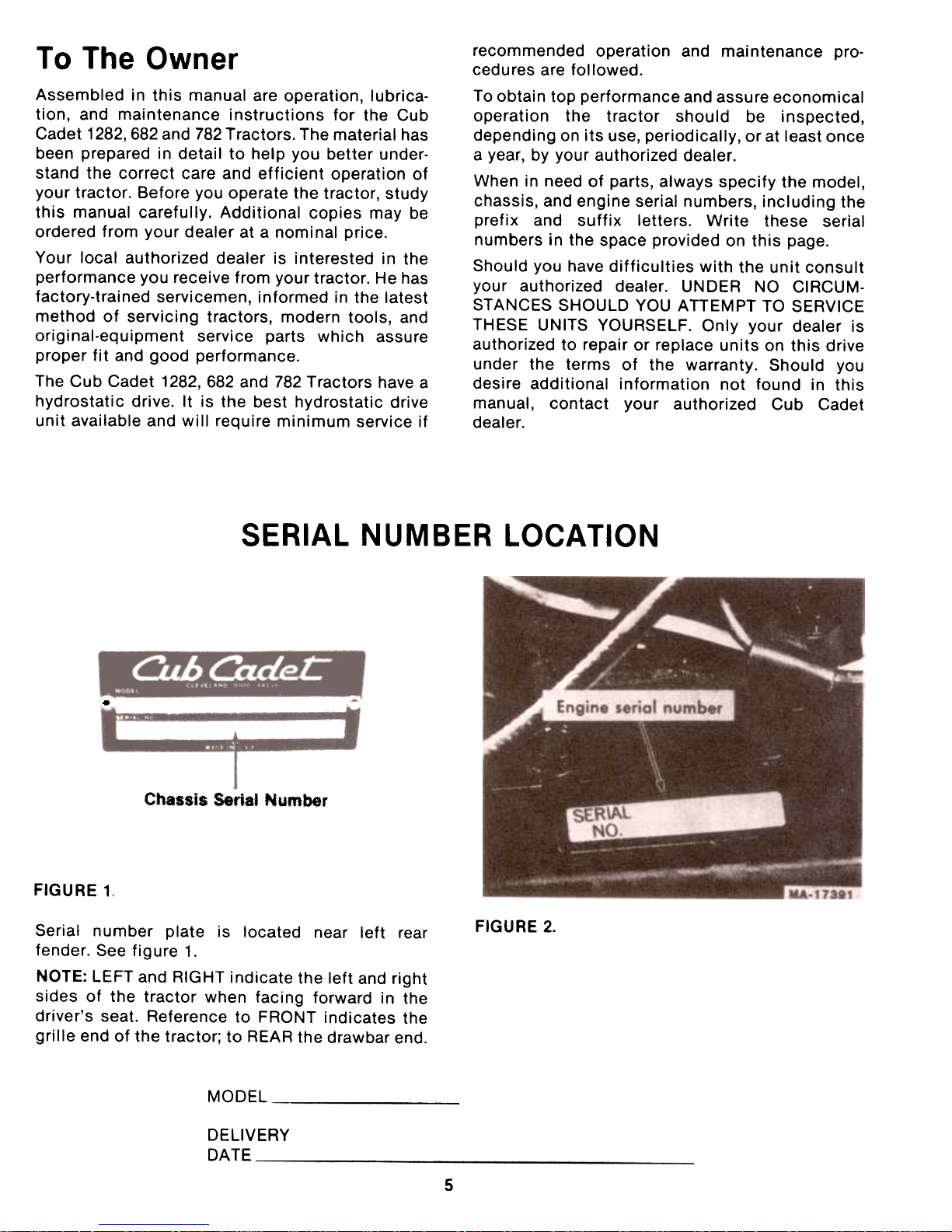
FIGURE 1,
FIGURE 2.
Serial number plate is located near left rearfender.
See figure 1.
NOTE: LEFT and RIGHT indicate the left and right
sides of the tractor when facing forward in the
driver's seat. Reference to FRONT indicates the
grille end of the tractor; to REAR the drawbar end.
MODEL
DELIVERY
DA TE -
5
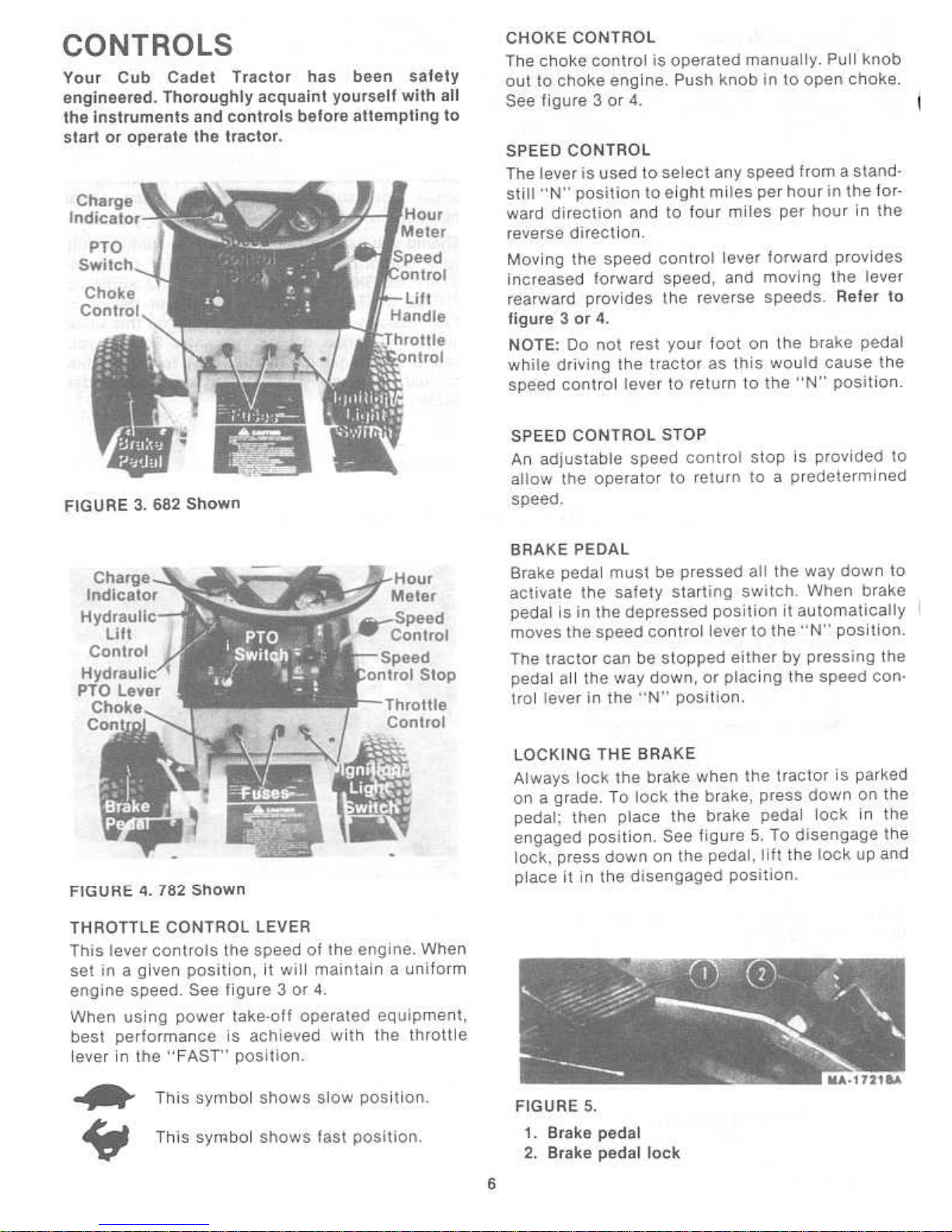
Page 6
Page 7

WARNING ~
The hydrostatic transmission will
not hold the tractor on a hill. In a
short period of time (depending on
the hill) the oil will drain from the
transmission and allow the tractor
to roll down hill. To avoid an acci-
dent and/or possible injury, lock the
brake.
the "OFF" position when shifting tractor into
reverse or the PTO will shut off automatically. To
re.engage the PTO, shift unit into neutral. Move
PTO switch to the "OFF" position and t:r,en move
PTO switch to "ON" position.
CHARGE INDICATORThis
instrument indicates whether the alternator
is charging or the battery is discharging. If it
shows- discharge continuously, investigate the
cause to avoid completely discharging the battery
and possible damage to the charging circuit.
HOUR METER
The hour meter is located on the instrument
panel. See figures 3, 4 and 7. It indicates the ac-
tual hours of engine operation, enabling the
operator to determine without guesswork, when
lubrication, change of oil or periodic inspections
are necessary. It also provides a means of computing cost of specific jobs. The hour meter
operates whenever the engine is running or the ig-
nition key is in the "ON" position.
IGNITION/LIGHT SWITCH
The combination lights and ignition switch is a
four position switch. See figure 6.
FIGURE 6.
~ WARNING:
Remove the key from the tractor
when the tractor is not in use to pre.
vent accidental starting and batterydischarge.
FRONT POWER TAKE.OFF (PTO)
The front power take-off is an electric clutch
operated by a toggle switch on the left side of the
instrument panel. See figure 3 or 4.
INTERLOCKS (Not Shown)
Interlock safety switches are located at and activated by the clutch-brake pedal, the PTO switch
and the seat.
The safety starting switches activated by the
brake pedal and the power take-off clutch switch
serve to prevent starting the engine accidentally.
The clutch-brake pedal must be depressed and
the PTO switch in the "OFF" position before
engine will start.
When using PTO operated equipment, the
operator must remain in tractor seat at all times. If
operator should leave tractor seat without turning
off the PTO switch, the engine will automatically
shut off. In addition, the PTO switch must be in
FIGURE 7.
FUSES (Electric Lighting and
Electric Power Take-Off Clutch)There
are two fuses on the tractor pedestal. The
fuse on the left is for the lights, the fuse on the
right is for the electric clutch. See figure 3 or 4.
LIFT HANDLE
1282 and 682 TractorsThe
lift handle is used to lift or lower equipment
used with the tractor. The equipment can be set in
multiple positions by depressing the button on
the handle and releasing it when the desired position is reached.
An additional feature has been provided to give increased float capability to the deck by depressing
the button and rotating the pin into the slot as
shown in figure 8.
7
Page 8
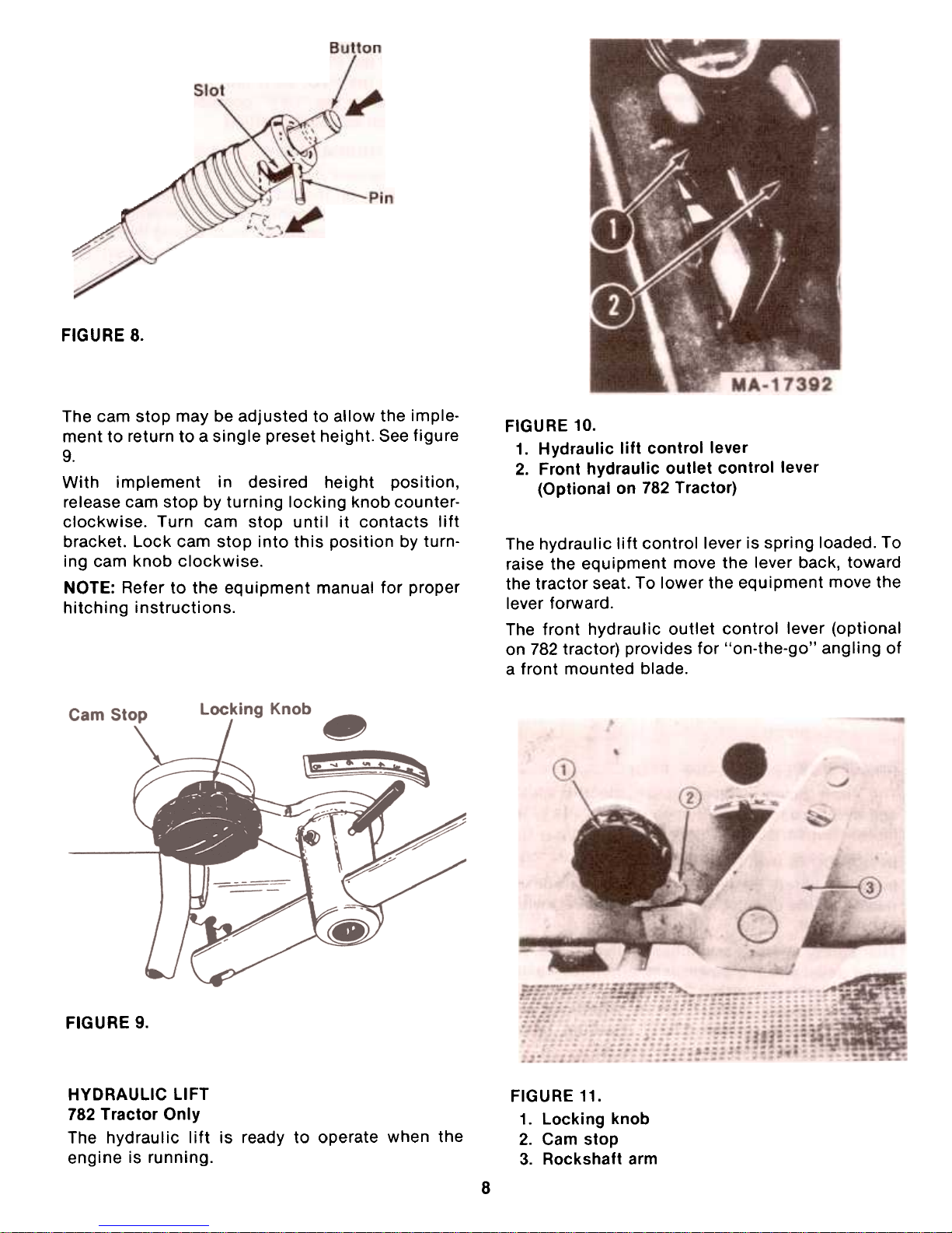
FIGURE 8.
FIGURE 10.
1. Hydraulic lift control lever
2. Front hydraulic outlet control lever
(Optional on 782 Tractor)
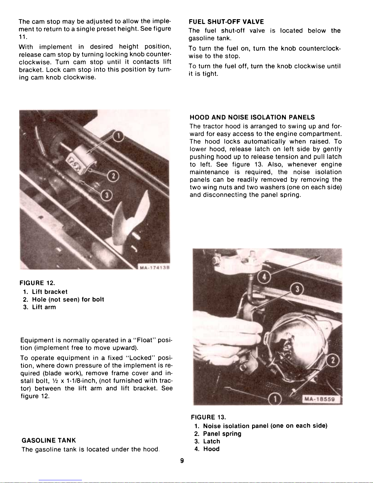
The cam stop may be adjusted to allow the imple-
ment to return to a single preset height. See figure9.
With implement in desired height position,
release cam stop by turning locking knob counterclockwise. Turn cam stop until it contacts lift
bracket. Lock cam stop into this position by turn-
ing cam knob clockwise.
NOTE: Refer to the equipment manual for proper
hitching instructions.
The hydraulic lift control lever is spring loaded. To
raise the equipment move the lever back, toward
the tractor seat. To lower the equipment move the
lever forward.
The front hydraulic outlet control lever (optional
on 782 tractor) provides for "on-the-go" angling of
a front mounted blade.
FIGURE 9.
HYDRAULIC liFT
782 Tractor Only
The hydraulic lift is ready to operate when the
engine is running.
FIGURE 11.
1. Locking knob
2. Cam stop
3. Rockshaft arm
8
Page 9
The cam stop may be adjusted to allow the imple-
ment to return to a single preset height. See figure
11.
With implement in desired height position,
release cam stop by turning locking knob counterclockwise. Turn cam stop until it contacts lift
bracket. Lock cam stop into this position by turn-
ing cam knob clockwise.
FUEL SHUT-OFF VALVE
The fuel shut-off valve is located below the
gasoline tank.
To turn the fuel on, turn the knob counterclockwise to the stop.
To turn the fuel off, turn the knob clockwise until
it is tight.
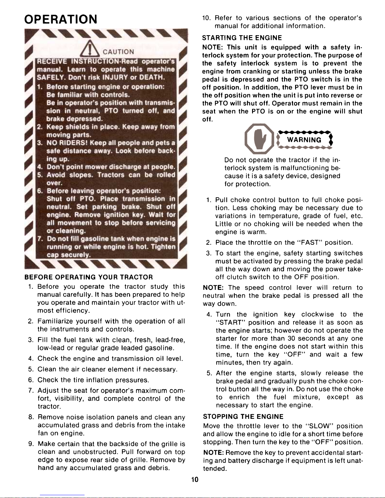
HOOD AND NOISE ISOLATION PANELS
The tractor hood is arranged to swing up and forward for easy access to the engine compartment.
The hood locks automatically when raised. To
lower hood, release latch on left side by gently
pushing hood up to release tension and pull latch
to left. See figure 13. Also, whenever engine
maintenance is required, the noise isolation
panels can be readily removed by removing the
two wing nuts and two washers (one on each side)
and disconnecting the panel spring.
FIGURE 12.
1. Lift bracket
2. Hole (not seen) for bolt
3. Lift arm
Equipment is normally operated in a "Float" position (implement free to move upward).
To operate equipment in a fixed "Locked" position, where down pressure of the implement is required (blade work), remove frame cover and in-
stall bolt, 1/2 x 1-1/8-inch, (not furnished with trac-
tor) between the lift arm and lift bracket. See
figure 12.
FIGURE 13.
1. Noise isolation panel (one on each side)
2. Panel spring
3. Latch
4. Hood
GASOLINE TANK
The gasoline tank is located under the hood.
9
Page 10
OPERATION
10. Refer to various sections of the operator's
manual for additional information.
STARTING THE ENGINE
NOTE: This unit is equipped with a safety interlock system for your protection. The purpose of
the safety interlock system is to prevent the
engine from cranking or starting unless the brake
pedal is depressed and the PTO switch is in the
off position. In addition, the PTO lever must be in
the off position when the unit is put into reverse or
the PTO will shut off. Operator must remain in the
seat when the PTO is on or the engine will shut
off.
, :::::.
WARNING- -.
Do not operate the tractor if the interlock system is malfunctioning because it is a safety device, designed
for protection.
1. Pull choke control button to full choke position. Less choking may be necessary due to
variations in temperature, grade of fuel, etc.
Little or no choking will be needed when the
engine is warm.
2. Place the throttle on the "FAST" position.
3. To start the engine, safety starting switches
must be activated by pressing the brake pedal
all the way down and moving the power take-
off clutch switch to the OFF position.
NOTE: The speed control lever will return to
neutral when the brake pedal is pressed all the
way down.
4. Turn the ignition key clockwise to the
"START" position and release it as soon as
the engine starts; however do not operate the
starter for more than 30 seconds at anyone
time. If the engine does not start within this
time, turn the key "OFF" and wait a few
minutes, then try again.
5. After the engine starts, slowly release the
brake pedal and gradually push the choke control button all the way in. Do not use the choke
to enrich the fuel mixture, except as
necessary to start the engine.
STOPPING THE ENGINE
Move the throttle lever to the "SLOW" position
and allow the engine to idle for a short time before
stopping. Then turn the key to the "OFF" position.
NOTE: Remove the key to prevent accidental starting and battery discharge if equipment is left unat-
tended.
BEFORE OPERATING YOUR TRACTOR
1. Before you operate the tractor study this
manual carefully. It has been prepared to help
you operate and maintain your tractor with ut-
most efficiency.
2. Familiarize yourself with the operation of all
the instruments and controls.
3. Fill the fuel tank with clean, fresh, lead-free,
low-lead or regular grade leaded gasoline.
4. Check the engine and transmission oil level.
5. Clean the air cleaner element if necessary.
6. Check the tire inflation pressures.
7. Adjust the seat for operator's maximum comfort, visibility, and complete control of the
tractor.
8. Remove noise isolation panels and clean any
accumulated grass and debris from the intake
fan on engine.
9. Make certain that the backside of the grille is
clean and unobstructed. Pull forward on top
edge to expose rear side of grille. Remove by
hand any accumulated grass and debris.
10
Page 11
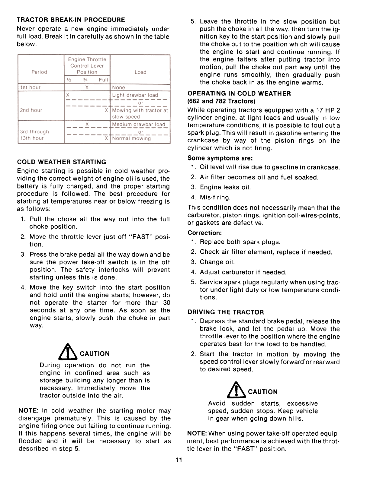
TRACTOR BREAK-IN PROCEDURE
Never operate a new engine immediately under
full load. Break it in carefully as shown in the tablebelow.
5. Leave the throttle in the slow position but
push the choke in all the way; then turn the ignition key to the start position and slowly pull
the choke out to the position which will cause
the engine to start and continue running. If
the engine falters after putting tractor into
motion, pull the choke out part way until the
engine runs smoothly, then gradually push
the choke back in as the engine warms.
OPERATING IN COLD WEATHER
(682 and 782 Tractors)
While operating tractors equipped with a 17 HP 2
cylinder engine, at light loads and usually in low
temperature conditions, it is possible to foul out a
spark plug. This will result in gasoline entering the
crankcase by way of the piston ri ngs on the
cylinder which is not firing.
Some symptoms are:
1. Oil level will rise due to gasoline in crankcase.
2. Air filter becomes oil and fuel soaked.
3. Engine leaks oil.
4. Mis-firing.
This condition does not necessarily mean that the
carburetor, piston rings, ignition coil-wires-points,
or gaskets are defective.
Correction:
1. Replace both spark plugs.
2. Check air filter element, replace if needed.
3. Change oil.
4. Adjust carburetor if needed.
5. Service spark plugs regularly when using trac-
tor under light duty or low temperature conditions.
COLD WEATHER STARTING
Engine starting is possible in cold weather pro-
viding the correct weight of engine oil is used, the
battery is fully charged, and the proper starting
procedure is followed. The best procedure for
starting at temperatures near or below freezing is
as follows:
1. Pull the choke all the way out into the full
choke position.
2. Move the throttle lever just off "FAST" posi-
tion.
3. Press the brake pedal all the way down and be
sure the power take-off switch is in the off
position. The safety interlocks will prevent
starting unless this is done.
4. Move the key switch into the start position
and hold until the engine starts; however, do
not operate the starter for more than 30
seconds at anyone time. As soon as the
engine starts, slowly push the choke in part
way.
DRIVING THE TRACTOR
1. Depress the standard brake pedal, release the
brake lock, and let the pedal up. Move the
throttle lever to the position where the engine
operates best for the load to be handled.
2. Start the tractor in motion by moving the
speed control lever slowly forward'or rearward
to desired speed.
~ CAUTION
During operation do not run the
engine in confined area such as
storage building any longer than is
necessary. Immediately move the
tractor outside into the air.
& CAUTION
Avoid sudden starts, excessivespeed,
sudden stops. Keep vehicle
in gear when going down hills.
NOTE: In cold weather the starting motor maydisengage
prematurely. This is caused by theengine
firing once but failing to continue running.
If this happens several times, the engine will be
flooded and it will be necessary to start as
described in step 5.
NOTE: When using power take-off operated equip-ment,
best performance is achieved with the throt-
tle lever in the "FAST" position.
Page 12

Advance throttle to operating speed (full
speed).4.
The operator must remain in tractor seat at all
times. If operator should leave tractor seat
without turning off the power take-off switch,
the engine will automatically shut off.5.
pro switch must be in the "OFF" position
when shifting the tractor into reverse or the
pro will shut off automatically. To re-engage
the pro, shift unit into neutral. Move pro
switch to "OFF" position and then move pro
switch to "ON" position.
Always be sure the rear wheels are free to turn.
Under any adverse conditions, do not attempt to
free the tractor by speeding up the engine and
suddenly engaging the clutch. Try backing out in-
stead of going forward.
~ CAUTION
Do not leave the seat of the tractor
without depressing the brake pedal
and setting the brake lock. If leaving
the tractor unattended, also turn the
ignition key off and remove the key.
ADJUSTMENTS
DRIVING ON SLOPES
Before operating the tractor on any slope, walk the
slope to look for possible hazards such as rocks,mounds,
ruts, stumps or other surface ir-
regularities which could cause an upset.
Back the tractor with implement up the steepest
portion of each slope you intend to work. If the
tractor cannot negotiate the slope in reverse, the
slope is too steep to be worked.
~ CAUTION
Always drive up or down the face of
a slope. Do not drive so that the
tractor may tip over sideways.
ADJUSTING THE SEAT
Before starting the tractor, adjust the seat to the
most comfortable driving position. Tilt the seat
forward over the steering wheel, loosen the four
cap screws in the seat support, and slide the seat
assembly forward or rearward to the position
which is most comfortable for the operator. See
figure 14.
Retighten the cap screws after the seat is ad-justed.
NOTE: The battery is located in a well under the
operator's seat for ease in servicing or replace-
ment when necessary.
Avoid turns when driving on a slope. If a turn must
be made, turn down the slope. Turning up a slope
greatly increases the chance of a rollover.
Avoid stopping when driving up a slope. If it is
necessary to stop while driving up a slope, start
up smoothly and carefully to reduce the possibility of flipping the tractor over backward.
STOPPING THE TRACTOR
Move the speed control lever to the "N" position
or use the standard brake pedal. Before dismounting always lock the brake pedal and turn the ignition "OFF." Also disengage the power take-off
control switch.
FIGURE 14.
ADJUSTING THE POWER
TAKE-OFF CLUTCH
The clutch is factory adjusted and should not require further adjustment under normal operatingconditions.
However, if the clutch fails to operate
properly check as follows:
OPERATING THE FRONT POWER
TAKE.OFF CLUTCH (PTO)
1. Move the throttle lever back to the medium or
"SLOW" position.
2. Flip the toggle switch to the "ON" position.
engage brake pedal lock,
lower equipment and shut off engine
before dismounting. Never start engine from ground.
Page 13

Check fuse on pedestal.
~ CAUTION
To avoid possible injury, always dis-
engage all clutches, move speed
control into neutral, depress the
brake, set the brake pedal lock and
turn the ignition "OFF" before working on the machine.
FIGURE 16.
Thread the clevis onto the brake rod one turn.
Reconnect the clevis to the jackshaft assembly.
There should be a minimum amount of clearance
(no drag) between the brake pads and the rotor.
See figure 17. If not, repeat adjustment .as
necessary.
Using a feeler gauge, check the air gap. See figure
15. Insert feeler gauge into one of three access
slots located around the outside of the brake
plate. The air gap should be .O10-.015-inches. Ad-
just the self-locking nuts to obtain the proper
clearance. Repeat the operation in all three access slots.
NOTE: If brake plate drags on clutch at
.O10-.015-inches air gap, increase air gap to
.O20-inches.
If the above procedure does not work, see your
authorized dealer.
FIGURE 17.
FIGURE 15.
1. Access slots
2. Brake plate
3. Self-locking nuts
ADJUSTING THE BRAKES
During normal operation of this machine, the
brakes are subject to wear and will require
periodic examination and adjustment.
With the brake pedal disengaged, remove the
clevis pinned end of one of the brake rod
assemblies from the jackshaft assembly by
removing the cotter pin from the clevis pin. See
figure 16.
NOTE: Figure 17 is shown with the wheel and
fender assembly removed for clarity.
Repeat the adjustment on the brake rod assembly
on the other side of the tractor.
Recheck brake adjustment and insure proper
brake operation before operating the tractor.
WHEEL ALIGNMENT
The front wheels should toe-in approximately 1/8".
Measure the distances A and B on the frontwheels.
See figure 18.
13
Page 14

NOTE: Dimension B should be approximately 1/8
inch less than dimension A.
18.
Front wheel adjustments.
To adjust the toe-in remove one ball joint, loosen
the lock nut "c" at the ball joint and turn the tie
rod ball joint in or out as required.
CARBURETOR ADJUSTMENTS
) ~C:~~:~~~ j
If any adjustments are made to the
engine while the engine is running
(e.g. carburetor), disengage all
clutches and blades. Keep clear of
all moving parts and be careful of
heated surfaces and muffler.
~ CAUTION
To avoid injury or an accident, be
sure the brake pedal is in the locked:
position, transmission is in neutral,
and any equipment is disengaged
before starting engine to make car-
buretor adjustments.
The carburetor is adjusted at the factory and
under normal operating conditions it will not require readjusting. However, if the engine does not
operate properly, what may appear to be a faulty
carburetor adjustment is in many cases a clogged
air filter. This possibility should be ruled out
before attempting to readjust carburetor. Refer to
"MAINTENANCE."
NOTE: To prevent possible damage to the carburetor needles, be very careful closing the carburetor needles before basic adjustments are
made. Improper adjustment of the carburetor may
result in engine damage.
1282 Tractor Only
FIGURE 19.
Tie rod and drag link ball joints.
FIGURE 20.
1. Governor control rod 5. Fuel shut-off valve
2. Idle adjusting screw 6. Fuel line
3. Throttle stop screw
4. High speed adjustment screw
TURNING RADIUSThe
front wheels should have an equal angle for
left and right turns. If adjustment is necessary.
remove ball joint and loosen lock nut "D", turn the
drag link ball joint clockwise or counterclockwise
as required. See figure 19.
~ CAUTION
Be sure all parts are reassembled
tight with cotter pins in place and
spread.
14
Page 15

:
WARNING:
Carbon monoxide fumes can be
fatal! Do not make any adj ustments
to the carburetor in a confined area
such as a storage building. Move the
tractor outside into the air.
682 and 782 Tractors
NOTE: Air cleaner has been removed from illustrations in order to show carburetor.
Adjusting the High-Speed Adjustment Screw
Turn the high speed adjustment screw counterclockwise approximately two turns from the
closed position and start the engine. Refer to
figure 20.
Be sure the choke is fully open (knob fully in)
when adjusting.
After the engine has reached normal operatingtemperature,
place the throttle lever in the fast
position and turn the high speed adjustment
screw clockwise to the leanest mixture that will
allow satisfactory acceleration and steady governor operation. Then, turn counterclockwise to the
richest mixture that allows satisfactory operation.The
difference between the rich and lean points is
about V2 turn. Set the mixture to the rich end of
this range.
If the engine misses and backfires under load, the
high speed mixture is too lean. The high speed adjustment screw must be turned counterclockwise
1/8 turn at a time until the condition is corrected.
If the engine shows a sooty exhaust and is slug-
gish under load, the high speed mixture is toorich.
The high speed adjustment screw must be
turned clockwise 1/8 turn at a time until the condition is corrected.
Adjusting the Idle Adjustment Screw
After the high speed ajdustment screw is ad-justed,
it may be necessary to readjust the idle adjustment screw as each affects the other. Refer to
figure 20.
Close the idle adjustment screw to its seat by
turning it clockwise; then open it one turn. Start
the engine and operate it at fast idling speed
(without any load) until thoroughly warm.
While the engine is running at fast idle speed, it is
advisable to screw in the throttle stop screw a few
turns to keep the engine from stopping when the
throttle lever is moved to the fully retarded
"SLOW" position. The engine will then be idling at
a fairly high speed and the throttle stop screw can
be backed out a little at a time until the desired
idle speed is obtained (1800 RPM).
If the engine misses or rolls while backing out the
throttle stop screw, the idle adjustment screw
may be adjusted in or out until the engine
operates smoothly. Speed up the engine for a few
seconds; then recheck the idle adjustment. A
slight adjustment in or out will give the smoothest
idle.
FIGURE 21.
1. Main fuel screw
2. Idle fuel screw
3. Idle speed screw
If readjustment becomes necessary, stop the
engine, then turn the MAIN and IDLE fuel adjusting screws all the way in, until they bottom
lightly. Refer to figure 21.
Main Fuel Adjustment
Preliminary setting-turn screw out 2V2 turns.
Final setting-start engine and raise engine
speed to maximum governed, no load speed. Turn
screw in just until engine speed decreases and
note the position of the screw. Now turn the screw
out. The engine speed will first increase, but then
decrease as screw is turned out. Note the position
of screw when engine speed starts to decrease.
Set the screw midway between the t,wo points
noted above.
Idle Speed Adjustment
Run engine at maximum governed, no load speed
for a minimum of 30 seconds, then allow engine
speed to fall to idle or put throttle into idle posi-tion.
Set engine speed to 1200 (:t 75 RPM) by turn-
ing the idle speed screw in or out.
Idle Fuel Adjustment
Set the idle fuel mixture by turning the idle fuel
screw out, from the closed position, 3/4 to 1 fullturn.
15
Page 16

Page 17

Page 18

Properly cleaned and installed air cleaner
elements are the best guarantee to continued
long and satisfactory engine life.
CLEANING ENGINE
This tractor has an air-cooled engine. Air must be
able to circulate freely around the engine, through
the screen, shroud, and over the fins of the
cylinder head and cylinder block. Keep these
areas free of accumulated dirt and trash or engine
will overheat and result in damaged moving parts.
Periodically clean the inside of the side panels
and grille for adequate cooling.
NOTE: This machine is designed to cool properly
with the engine side panels in place. Operating
the machine without panels in place may result in
inadequate cooling.
SPARK PLUGS
Cleaning Spark Plug
Clean spark plugs with a penknife or wire brush
and solvent. If electrode is burned away or the
porcelain is cracked, replace with new plug.
NOTE: Do not sandblast or use any abrasive
machines to clean spark plugs; because any grit
introduced into the engine could cause severe
damage.
LIGHTS
The headlights are sealed-beam units. Refer to
"SPECIFICATIONS" when replacement is
necessary.
To replace the taillight lamp, remove socket and
bulb from the back of the taillight by rotating
socket 1/4 turn. Refer to "SPECIFICATIONS".
FUSES
Always use the same capacity fuse for replace-
ment. Refer to "SPECIFICATIONS." If the lights
fail or the electric clutch does not engage, check
the appropriate fuse.
To install a new fuse, press in on the fuse housing
cap and turn counterclockwise to remove it from
the fuse housing. Remove the old fuse and
replace it with a new one. Then reassemble the
cap to the housing.
NOTE: The fuse on the left is for the lights; the
fuse on the right is for the electric clutch.
BATTERY INFORMATION
~~~~R:~~G~J
FIGURE 24.
NOTE: Remove all dirt from around the spark
plugs before removing.To
remove spark plugs, always use a spark plugwrench.
Check gap after every 100 hours of opera-tion.
~ CAUTION
To avoid possible injury, be sure
engine is off and cool before making
any adjustments or repairs.
Replace a defective plug with a new plug. Set gap
at .O25-inch. See figure 24. Tighten plug to 7-15 ft-
Ibs. See your authorized dealer for the correct
replacement plug.
Battery acid must be handled with great care
as contact with it can burn and blister the skin.
It is also advisable to wear protective clothing
(goggles, rubber gloves and apron) when work-
ing with it..
B. Should battery acid accidentally splatter into
the eyes or onto the face, rinse the affected
area immediately with clean cold water. If
there is any further discomfort, seek prompt
medical attention.
C. If acid spills on clothing, first dilute it with
clean water, then neutralize with a solution of
ammonia/water or baking soda/water.
D. Since battery acid is corrosive, do not pour it
into any sink or drain. Before discarding empty
electrolyte containers, rinse them with a
neutralizing solution.
E. NEVER connect or disconnect charger clips to
battery while charger is turned on as it can
cause sparks.
18
Page 19

F. Keep all lighted materials (cigarettes,
matches, lighters) away from the battery as the
hydrogen gas generated during charging can
be combustible.
G. As a further precaution, only charge the battery
in a well-ventilated area.
.Always shield eyes, protect skin and clothing
when working near batteries.
Specific Gravity Freezing Point
1.265 -710 F.
1 .250 -620 F.
1.200 -160 F.
1.150 50 F.
1.100 160 F.
~ CAUTION
All batteries discharge during
storage.
4. Recharge battery whenever the specific gravity is less than 1.225, before returning to service or every two months, whichever comes
first.
,' ), DANGER:
BATTERIES CONTAIN SULFURIC
ACID AND MAY CONTAIN EXPLOSIVE GASES (when electrolyte has
been added).
KEEP BATTERIES OUT OF THE REACH OF CHIl-DREN.
COMMON CAUSES FOR BATTERY FAILURE
1. Overcharging
2. Undercharging
3. Lack of water
4. Loose hold downs and/or corroded connec-
tions
5. Excessive loads
6. Battery electrolyte substitutes
7. Freezing of electrolyte
NOTE: These failures do not constitute warranty.
BATTERY REMOVAL OR INSTAllATION
'~;:R~~N~G~;::;'*
When removing the battery, follow
this order of disassembly to prevent
your wrench from shorting against
the frame.
MAINTENANCE OF BATTERY
1. Check electrolyte level periodically (at least
every two weeks). Keep the level to the split
rings. Use only distilled water or a good quali-
ty drinking water. Never add acid or any other
chemicals to the battery after initial activa-
tion.
2. The battery should be checked with a
hydrometer after every 25 hours of operation.
If the specific gravity is less than 1.225, the
battery should be recharged. Maximum
charge rate 5 AM PS.
3. Coat the terminals and exposed wire with a
thin coat of grease or petroleum jelly for
longer service and protection against corro-
sion.
4. The battery should be kept clean. Any
deposits of acid should be neutralized with
baking soda and water. Be careful not to get
this solution in the cells.
5. Avoid tipping the battery. Even a "sealed" battery will leak electrolyte when tipped.
1. Remove the Negative cable.
2. Remove the Positive cable.
To install a battery:
1. Attach the Positive cable.
2. Attach the Negative cable.
JUMP STARTING
1. Attach the first jumper cable from the Positive
terminal of the good battery to the Positive
terminal of the dead battery.
2. Attach the second jumper cable from the
Negative terminal of the good battery to the
FRAME OF THE UNIT WITH THE DEAD BAT-
TERY.
STORAGE OF THE BATTERY
1. When storing battery for extended periods,
disconnect battery cables. Removing battery
from unit is recommended.
2. Keep the exterior of the battery clean,
especially the top. A dirty battery will
discharge itself.
3. Check the battery with a hydrometer. The battery must be stored with a full charge. A
discharged battery will freeze.
19
Page 20

*
WARNING:
Failure to use this starting procedure could cause sparking, and
the gases in either battery could ex-plode.
TIRES
Keep the pneumatic tires properly inflated. Overinflation will cause operator discomfort. Underinflation will cause short tire life.
Inflate the front and rear tires for normal or heavy
load operations as shown in the following table.
Tire Size
Front Tires
16 x 6.50-8
Rear Tires
23 x 10.50-12
Pounds per square inch
12
10
1. Working outdoors, drain all fuel from the fuel
tank. Use a clean dry cloth to absorb the small
amount of fuel remaining in the tank, then run
the engine until all fuel in the carburetor is ex-
hausted.
2. Drain all the oil from the crankcase (this
should be done after the engine has been
operated and is still warm) and refill the crankcase with clean new oil.3.
Disconnect the spark plug wires and remove
the spark plugs from the cylinders. Pour about
2 or 3 tablespoons of engine oil into each
cylinder, and then turn the engine over several
times to spread out the oil. Replace the spark
plugs but do not connect the wires.4.
Clean the engine and the entire tractor
thoroughly.5.
Lubricate all lubrication points and wipe the
entire machine with an oiled rag in order to
protect the surfaces.6.
Follow battery storage instructions on page
19.7.
Protect tires and seat from sunlight. Inflate
tires at regular intervals.
Always see that the tire valve caps are in place
and tightened securely to prevent loss of air and
protect the valve core and stem.
Do not overload the tractor tires by mounting
equipment on the tractor which exceeds the load
capacity of the size of the tires on the tractor.
OPTIONAL
EQUIPMENTAND
ACCESSORIES
Mounting Tires On The RimAfter
mounting a new or old tire on the rim, inflate
it to 20 pounds pressure to seat the tire bead onthe
rim flange. Then deflate the tire to the correctoperating
pressure.
NOTE: After the first 10 hours of operation, check
and retorque the wheel lug nuts (both sides) to 35Ibf.
ft. to make sure they have seated properly.
When you purchased your tractor, you probably
had it completely equipped for your particular
needs at the time. However, later you may wish to
obtain optional equipment or accessories. These
items and other allied equipment can be purchased from, and installed by, your authorizeddealer.
The tractor is used for so many different types ofwork,
and because it is called on to operate under
so many different conditions, a variety of equip-
ment is available to adapt it to the requirements of
the user. Refer to equipment catalog.
If the machine is to be inoperative for a periodlonger
than 30 days, the following procedures arerecommended:
20
Page 21

Page 22

Page 23

TROUBLE SHOOTING
Possible Cause
Possible Remedy
ENGINE OVERHEATS
Insufficient cool air, dirty air intake screen,
shroud, cooling fins, or dirty grille.
Lean carburetor adjustment.
Oil level incorrect.
Keep the air intake area and cooling fins clean;
Refer to "MAINTENANCE".
Readjust; Refer to "ADJUSTMENTS".
Engine oil level must not be over the "FULL" mark
or below the "LOW" mark. Refer to "MAIN-
TENANCE".
* See your authorized dealer.
LUBRICATION
TABLE
Check
at
Hours
Change
at
Hours
Anticipated Air Temperature
Point of Lubrication
Capacit~
Above + 32°F.
+ 32°F. to OaF.
Below O°F.
Engine crankcase
3 pt.
(1282)
3 pt.
(682
and
782)
I.H. Low Ash En-
gine Oil SAE-30
Note: Do not
substitute 10W-30
or 10W-40
I.H. No. 1@
Engine Oil
SAE-5W-20
or
SAE-5W-30
Check
before
each
use
H. Low Ash
Engine Oil
SAE.10W
25
IH Hy .Tran@ Fluid
If fluid is used which does not meet requirements
of IH 8-6 Specifications, Cub Cadet will not be
responsible for substandard performance.
Failures due to use of improper fluid is not
covered by warranty. For maximum protection,
use IH Hy .Tran@ Fluid.
Hydro-drive unit
mounted on
transmission case
with filter
30 Add as
lneeded
14 pt.
Approx.
100
or
Yearly
Two strokes of the lubricator using IH-251 H EP
grease or equivalent No.2 multi-purpose
lithium grease.
1/4 lb.
Steering gear
housing
Use IH-251 H EP grease or equivalent No.2 multi-purpose
lithium grease and apply two or three strokes of the lubrica-
tor or sufficient grease to flush out old grease and dirt.
Steering knuckles &
front axle pivot bolt
10
100
or
Yearly
Remove front wheels and pack bearings with
IH-251 H EP grease or equivalent No.2 multi-
purpose lithium grease and reinstall wheels.
Front wheel
bearings
;t,~
Page 24

Be certain that all lubrication fittings are assembled in place, using the lubrication illustrations asa
guide.
lubricate the tractor thoroughly before tak-
ing it to the field. Use a pressure lubricating gun.
Be sure all fittings are free from dirt and paint so
the lubricant is certain to enter the bearing.
Always force the lubricant through the full length
of each bearing until it emerges at the end, carrying with it the worn lubricant and any dirt that may
have entered the bearing.
Miscellaneous working parts not provided with
lubrication fittings should be oiled daily with a
good grade of lubricating oil.
Lubricant is cheap. Use plenty of it. Worn parts
can be expensive to replace.
Keep your supply of lubricating oil and grease stored in clean containers,
and covered to protect from dust and dirt.
Keep the lubricating gun nozzle clean and wipe dirt from grease fittings
before lubricating.
symbols in the illustration indicate the
method of application and the hourly intervals to
apply the lubricant.
_.r:-~ Use a pressure lubricating gun and ap-
\ j ply IH 251 H EP grease (or equivalent No.
-2 multi-purpose lithium grease) sufficient to flush out the old grease and dirt.
Lubricate at hourly intervals indicated on sym-
bols.
use to check engine oil before
each use.
24
Page 25

Page 26

Engine filler cap
and dipstick.
1.
LUBRICATION GUIDE
-Before Each Use
Check the oil (with the engine stopped) and add sufficient
new oil to bring it to the "FULL" mark on the dipstick. Do
not overfill. Do not operate the engine if the oil level is
below the "LOW" mark on the dipstick.
-After Every 10 Hours of Operation
Use IH 251 H EP grease or equivalent No.2 multi-purpose
lithium grease and apply sufficient grease to flush out old
grease and dirt.
2-
Steering knuckles (2).
(Both sides)
NOTE: After the first 10 hours only, remove the oil filterand
replace with a new filter. Refer to "MAINTENANCE."Change
the oil filter after 50 hours and every 100 hours of
operation thereafter.
3-
Transmission oil filter.
Use IH 251 H EP grease or equivalent No.2 multi-purpose
lithium grease and apply sufficient grease to flush out old
grease and dirt. NOTE: It may be necessary to rotate the
front axle to reach the grease fitting.
After Every 25 Hours of Operation
4.
Front Axle pivot bolt.
(Right side)
While the oil is warm, remove the drain plug (5) and drain
all of the oil from the crankcase. Replace the drain plug.
Refill the crankcase with new oil up to the "FULL" mark
on the dipstick. Refer to the "LUBRICATION TABLE" for
the proper quantity and viscosity to use.
5-
Engine
oil drain plug.
6-
Transmission
oil leveland
fill tube.
Check the oil with the engine stopped. Keep the lubricant
up to "FULL" mark on dipstick (6).
-After Every 50 Hours of Operation
7.Transmission
oil filter.
8-
Transmission oil filter.
NOTE: After the first 50 hours only, remove the oil filter
and replace with a new filter. Refer to "MAINTENANCE."
Change the oil filter every 100 hours of operation
thereafter.
Every 100 Hours of Operation
Change the oil filter and replace with a new filter. Refer to
"MAINTENANCE."
9-Steering gear housing.
(Center bottom)
Once a year, apply two strokes of the lubricator, using IH
251 H EP grease or equivalent No.2 multi-purpose lithium
grease.
NOTE: To locate the lubrication fitting, turn the front
wheels to the maximum right turn position. Then reach up
under the right side of the tractor frame to locate the fit-ting.
Once a year, apply a small amount of IH 251H EP grease
or equivalent No.2 multi-purpose lithium grease in theslots.
Speed Control Linkage
10-Cam plates.
Miscellaneous
Brake pedal shaft
Lubricate the brake pedal shaft and linkage with eight or
ten drops of engine oil.
26
Page 27

Page 28

Page 29

The cam stop may be adjusted to allow the imple-
ment to return to a single preset-height. See figure
11
With implement in desired height position,
release cam stop by turning locking knob counter-
clockwise. Turn cam stop until it contacts lift
bracket. Lock cam stop into this position by turn-
ing cam knob clockwise.
The fuel tank filler cap has an air vent. Keep
the vent open at all times to assure proper
flow of the fuel.
NOTE: Gasohol is not approved for use
by the engine manufacturer and
should not be used. The use of
gasohol may damage the engine.
FUEL SHUT-OFF VALVE
The fuel shut-off valve is located below the
gasoline tank.
To turn the fuel on, turn the knob counterclock-
wise to the stop.
To turn the fuel off, turn the knob clockwise until
it is tight.
HOOD AND NOISE ISOLATION PANELS
The tractor hood is arranged to swing up and for-
ward for easy access to the engine compartment.
The hood locks automatically when raised. To
lower hood, release latch on left side by gently
pushing hood up to release tension and pull latch
to left. See figure 13. Also, whenever engine
maintenance is required, the noise isolation
panels can be readily removed by removing the
two wing nuts and two washers (one on each side)
and disconnecting the panel spring.
FIGURE 12.
1. Lift bracket
2. Hole (not seen) for bolt
3. Lift arm
Equipment is normally operated in a "Float" posi-
tion (implement free to move upward).To
operate equipment in a fixed "Locked" posi-tion,
where down pressure of the implement is required (blade work), remove frame cover and install bolt, 1/2 x 1-1/8-inch, (not furnished with trac-
tor) between the lift arm and lift bracket. See
figure 12.
GASOLINE TANK
The gasoline tank is located under the hood.
FUEL SYSTEM
This engine is designed to operate on
unleaded or leaded gasoline with a 91
minimum octane rating (Research Method), or
a minimum Antiknock Index (RON + MON)/2
of 87. Antiknock Index is posted on dispensing pumps.
The use of unleaded gasoline will increase
spark plug and valve life, maintain engine
performance longer, and reduce rust and corrosion of the engine while stored.
FIGURE 13.
1. Noise isolation panel (one on each side)
2. Panel spring
3. Latch
4. Hood
1 096 822 R1 4-83
PRINTED IN UNITED STATES OF AMERICA
31
Page 30

MAINTENANCE
To aid starting, the selection of crankcase
lubricating oils should be based on the lowest an.
ticipated temperatures until the next drain period.
Refer to "lUBRICATION TABLE".
We recommend IH Low Ash Engine Oil for
gasoline engines. IH Low Ash Engine Oil
exceeds API Service Classification SE. It is
specifically designed for heavy duty service
in gasoline engines, and is formulated to
minimize metallic deposits, lengthen spark
plug and valve life. IH Low Ash Oil used with
unleaded gasoline is the ideal combination to
maintain performance and extend engine life.
the "FULL" mark. For oil capacity refer to the
"SPECIFICATIONS" and "LUBRICATION TABLE"
section.
Remove the cap and dipstick and fill to the full
mark on the dipstick. POUR SLOWLY.
Capacity 3 pints. When checking the oil level,
push the dipstick assembly firmly but slowly
until cap bottoms on tube. DO NOT OVERFill. Dipstick assembly must be pushed fully
into tube at all times when engine is operat-
ing.
HYDROSTATIC DRIVE HYDRAULIC FLUID
FIL TER
Remove the throw-away can-type filter and replace
with a new filter after the first 10 hours and 50
hours of operation, and every 100 hours of opera-
tion thereafter.
NOTE: Clean the outside area before removing the
filter to keep dirt from getting into the transmission case. If a mower is mounted on the tractor,
the mower must be lowered to facilitate removal
of the filter.
To remove the filter, turn the filter counterclock-
wise using an automotive type filter wrench.
Before installing the new filter, apply a coating of
oil on the filter gasket. Thread the filter on by hand
until tight enough to seat the gasket. Loosen the
filter. Then turn it until the gasket contacts the
base. Tighten the filter an additional one half turn.
Start engine and allow it to run for a few minutes.
Shut engine off and check for leaks, check oil
level in transmission case.
AIR CLEANER
Dry Type (1282 Tractor Only)
If other than IH Low Ash Engine Oil is used it
must meet API Service Classification SE. For
maximum engine life select API SE oils with
lowest levels of barium, calcium, or magnesium additives and minimum ash content
(approximately 0.5%). Lubricant suppliers will
normally furnish this information on their
engine oils.
Multi-viscosity numbered oils such as SAE
10W-30 or SAE 10W-40 must not be used above 32
degrees Fahrenheit.
Regularly check the oil level of the engine crankcase to see that it is filled to the correct level.
NOTE: Check the oil level only while the engine is
stopped.
Always keep the oil level between the "FULL" and
the "LOW" marks on the dipstick. When checking
the oil level the dipstick must be withdrawn and
wiped clean, then inserted all the way and
withdrawn for a true reading.
Filling the Crankcase
To fill the crankcase with oil, place the tractor on a
level surface. Clean the area around oil fill before
removing combination oil filler cap and dipstick.
NOTE: Never overfill the engine crankcase.
Engine may overheat and/or damage may result if
the crankcase is below the "LOW" mark or over
.~-- ~
All engine air used for combustion is filtered by a
dry type air cleaner to assure long engine life.
NOTE: Left engine side panel must be removed to
have access to the air cleaner.
Service the air cleaner element when a loss of
power is noticeable. Discard used element and
replace with a new one at least once a year.
1 096 822 R1 4-83
PRINTED IN UNITED STATES OF AMERICA
32
ENGINE OIL
The engine crankcase is filled with ship-away
oil. This oil may be used for the first 5 hours of
engine operation at temperatures between
+90 degrees F. and 0 degrees F. If temperatures are not within this range, drain the
oil from the crankcase and replace with new
oil as specified in the "LUBRICATION
TABLE". The engine oil must be drained and
replaced with new oil every 25 hours of
engine operation.
Page 31

Page 32

Page 33

Page 34

1-Engine filler cap
and dipstick.
LUBRICATION GUIDE
-Before Each Use
Check the oil (with the engine stopped) and add sufficient
new oil to bring it to the "FULL" mark on the dipstick. Do
not overfill. Do not operate the engine if the oil level is
below the "LOW" mark on the dipstick.
-After Every 10 Hours of Operation
Use IH 251 H EP grease or equivalent No.2 multi-purpose
lithium grease and apply sufficient grease to flush out old
grease and dirt.
2-Steering knuckles (2).
(Both sides)
NOTE: After the first 10 hours only, remove the oil filter
and replace with a new filter. Refer to "MAINTENANCE."
Change the oil filter after 50 hours and every 100 hours of
operation thereafter.
3- Transmission oil filter.
4-Front Axle pivot bolt.
(Right side)
Use IH 251 H EP grease or equivalent No.2 multi-purpose
lithium grease and apply sufficient grease to flush out old
grease and dirt. NOTE: It may be necessary to rotate the
front axle to reach the grease fitting.
-After Every 25 Hours of Operation
While the oil is warm, remove the drain plug (5) and drain
all of the oil from the crankcase. Replace the drain plug.
Refill the crankcase with new oil up to the "FULL" mark
on the dipstick. Refer to the "LUBRICATION TABLE" for
the proper quantity and viscosity to use.
5-Engine oil drain plug.
6- Transmission oil level
and fill tube.
Check the oil with the engine stopped. Keep the lubricant
up to "FULL" mark on dipstick (6).
-After Every 50 Hours of Operation
7- Transmission oil filter.
8- Transmission oil filter.
NOTE: After the first 50 hours only, remove the oil filter
and replace with a new filter. Refer to "MAINTENANCE."
Change the oil filter every 100 hours of operation
thereafter.
-Every 100 Hours of Operation
Change the oil filter and replace with a new filter. Refer to
"MAINTENANCE."
9-Steering gear housing.
(Center bottom)
Once a year, apply two strokes of the lubricator, using IH
251 H EP grease or equivalent No.2 multi-purpose lithium
grease.
NOTE: To locate the lubrication fitting, turn the front
wheels to the maximum right turn position. Then reach up
under the right side of the tractor frame to locate the fit-
ting.
Once a year, apply a small amount of IH 251 H EP grease
or equivalent No.2 multi-purpose lithium grease in the
slots.
Speed Control linkage
10-Cam plates.
Miscellaneous
Brake pedal shaft
Lubricate the brake pedal shaft and linkage with eight or
ten drops of engine oil.
36
1 096822 R1 4-83
PRINTED IN UNITED STATES OF AMERICA
Page 35

Page 36

 Loading...