

Page 1
SERVICE MANUAL
S962A
The Monitor Specialists
EDITION 1
DEC. 2003
Page 2

C
T
X
C
T
X
C
T
X
S962A
TABLE OF CONTENTS
CONTENTS PAGE
Sections
1. Scope 4
2. Input requirements 5
3. Electrical Characteristics 6~10
4.Trouble Shooting 11~16
5. Parts List 17
Service Manual
Appendix
1. Main Board Circuit Diagram
2. Assembly Explosion Drawing
2
Page 3

C
T
X
C
T
X
C
T
X
S962A
Service Manual
Copyright © 2003 by Chuntex Electronic Co., Ltd.
The CTX SERVICE MANUAL is published by Chuntex Electronic Co., Ltd
All rights reserved. No part of this manual may be used, copied, reproduced, or transmitted in any form or by
any means for any purpose without the express written permission of the publisher.
The publisher has been trying its best to make this publication perfect, and in this manner takes no
responsibility for the use of any of the materials or methods described in this manual, or for the products
thereof. Neither will the publisher be responsible for any damages caused by misuse or misquotation.
Information in this manual is subject to change by the publisher without any notice in advance.
CTX is a registered trademark of Chuntex Electronic Co., Ltd.
3
Page 4
C
T
X
C
T
X
C
T
X
S962A
1. SCOPE
This specification defines the design and performance requirements for the 19” SXGA TFT
LCD display monitor “S962A “.
The features of “S962A” is listed in the following table:
Feature Description
1 Universal input AC/DC power supply inside the monitor
2 Analog RGB interface (VGA ) 30~80KHz, 59~75Hz, 135MHz
3 19” SXGA 1280*1024, TFT LCD panel
4
Function keys * 5 : Power On/Off, ESC, △ (up), ▽ (down),
Direct Acess function keys : △ for
5
audio mute function
6 Green/Amber LED indicator for power on/power saving
7 Plug & play support with DDC2B protocol installed.
8 Power saving mode compliant with Energy Star
9 OSD (on screen display) MENU operation
9.1 Brightness adjustment
9.2 Contrast adjustment
9.3 Auto tune function (VGA)
9.4 Color selection
9.5 Image adjustment
9.6 Language selection
9.7 OSD position adjustment
9.8 Reset function
9.9 1W * 2 Audio function inside the monitor
9.10 Volume adjust by OSD
contrast function, ▽ for brightness function , ESC for
(enter)
Service Manual
4
Page 5

C
T
X
C
T
X
C
T
X
S962A
2. INPUT REQUIREMENTS
2.1 Input Power
2.1.1. Power Source
2.1.2. Power Consumption
2.1.3. AC Line Drop Out
2.1.4. AC Wave Distortion
2.1.5. In-rush Current
2.1.6. Power Cord
2.2 Display Input
2.2.1. Analog Input RGB Video
2.2.1.1 Sync Signal
100 ~ 240 Vac, + -10%, 50/60 Hz
Normal operating mode
Audio function is operating at max output: ≦ 43W
w/o audio function: ≦ 36W
Power saving mode
Audio function is operating at max output: ≦ 7W
w/o audio function: ≦ 2W
Power switch off: ≦ 1.5W
Picture must not disappear while AC 100 V input drop out(10ms, 100%)
10% max. Permitted
50 A max at 240 Vac cold start
Detachable, 3P with ground type.
Analogue, 0.0 to 0.7 V peak to peak
Separate RGB
Input impedance 75 Ohm
Positive polarity
Separate horizontal & vertical sync (3.3V & 5V)
Low level 0.8 V maximum
High level 2.0 V minimum
Positive or negative polarity
Service Manual
5
Page 6
C
T
X
C
T
X
C
T
X
S962A
Analog Input Connection a. Captive cable length 1.5M in LCD Monitor end, D-sub
male connector in another end.
b. A female Mini D-sub 15 pin base.
Pin 1 Red
Pin 2 Green
Pin 3 Blue
Pin 4 No Connection
Pin 5 Ground
Pin 6 R Return
Pin 7 G Return
Pin 8 B Return
Service Manual
Pin 9 No Connection
Pin 10 Ground
Pin 11 Ground
Pin 12 SDA
Pin 13 H. Sync
Pin 14 V. Sync
Pin 15 SCL
2.3 Audio Input
2.3.1 Audio Input Signal Right &Left channels.
Input level: 1Vrms(typ), 2Vrms(max)
Input Impedance: 15Kohm
2.3.2 Audio Input Connection a. Detachable stereo phone head in two ends signal cable.
b. A female stereo phone jack base.
3. ELECTRICAL CHARACTERISTICS
3.1 LCD Panel
3.1.1. Type 19” diagonal, SXGA resolution, color TFT-LCD
3.1.2. Pixel structure
3.1.3. Gray scale 16.7 million colors.
3.1.4. Surface treatment
3.1.5. Backlight
R/G/B sub-pixels in vertical stripes
1280 x 1024 array matrix
a-Si TFT active matrix
3H hard coating, anti-static,anti-glare
Integral CCFL, type to support field replacement.
Life time 30000 hours @ 25C, 50% of initial value.
3.1.6 Pixel Faults
Model
Project
Pixel Faults type
Type1
Type2
Type3
Type4
Type5
Type6
Note 1: Bright pixels in full black pattern.
Note 2: Dark pixels in full white pattern
Note 3: fault Pixel / Sub-Pixel: The pixel or sub-pixel is abnormal but not bright/dark pixel.
Note 4: Fault Cluster: Two or more Pixels/Sub-pixels with faults within 5 * 5 block of pixels.
3.2 Modes and Timing Comparability
Bright Pixels (Note 1)
Dark Pixels (Note 2)
Fault Pixels / Sub-Pixels (Note 3)
Cluster of type1 or type 2 faults (Note 4)
Cluster of type3 faults (Note4)
Total Pixel Faults
6
S962A
LBL19SS4HA01
≦ 5
≦ 5
≦ 3
≦ 2
≦ 3
≦ 8
Page 7

C
T
X
C
T
X
C
T
X
S962A
3.2.1Analog Input Supported Timing VESA Standard mode:
Display Format IBM VGA VESA VESA VESA VESA VESA
Horizontal Dots 720 640 640 640 800 800 800
Vertical lines 400 480 480 480 600 600 600
Horizontal Frequency
Vertical Frequency (Hz) 70 59.94 72.809 75 60.317 72.188 75.000
Pixel Rate (MHz) 28.322 25.175 31.5 31.5 40 50 49.5
H. Sync. Polarity - - - - + + +
V. Sync. Polarity + - - - + + +
O ms (Period) 16.683 13.735 13.333 16.579 13.853 13.333
P ms (Pulse Width) 0.064 0.079 0.080 0.106 0.125 0.064
Q ms (Back Porch) 1.048 0.739 0.427 0.607 0.478 0.448
R ms (Active Area) 12.711 15.253 12.678 12.800 15.840 12.480 12.8
S ms (Front Porch) 0.318 0.237 0.027 0.026 0.770 0.021
Display Format VESA VESA VESA VESA VESA VESA
Horizontal Dots 1024 1024 1024 1152 1280 1280
Vertical lines 768 768 768 864 1024 1024
Horizontal Frequency
Vertical Frequency (Hz) 60.004 70.069 75.029 75 60.013 75.025
Pixel Rate (MHz) 65.0 75 78.75 108 108 135
H. Sync. Polarity - - + + + +
V. Sync. Polarity - - + + + +
O ms (Period) 16.666 14.272 13.238 13.333 16.663 13.329
P ms (Pulse Width) 0.124 0.106 0.050 0.044 0.047 0.038
Q ms (Back Porch) 0.6 0.513 0.466 0.474 0.594 0.475
R ms (Active Area) 15.88 13.599 12.795 12.8 16.006 12.804
S ms (Front Porch) 0.062 0.054 0.017 0.015 0.016 0.012
31.469 37.861 37.5 37.879 48.077 46.875
31.778 26.413 26.667 26.4 20.8 21.333
3.813 1.270 2.032 3.2 2.4 1.616
1.907 4.063 3.810 2.2 1.28 3.232
25.422 20.317 20.317 20.0 16.0 16.162
0.636 0.763 0.508 1.00 1.12 0.323
48.363 56.746 60.023 67.5 63.981 79.976
20.667 17.707 16.660 14.815 15.631 12.504
2.092 1.813 1.219 1.185 1.180 1.067
2.462 1.920 2.235 2.370 2.065 1.837
15.754 13.653 13.003 10.667 11.797 9.481
0.369 0.321 0.203 0.593 0.590 0.119
Service Manual
VGA Support Mode
7
Page 8

C
T
X
C
T
X
C
T
X
S962A
1280 * 1024 @70Hz, 72Hz
1280 * 960 @ 60Hz, 70H, 72Hz, 75Hz
1280 * 720 @ 60Hz
1152 * 864 @ 60Hz, 70Hz, 72Hz
1024 * 768 @ 72Hz
800 * 600 @ 70Hz
640 * 480 @ 70Hz
640 * 350 @ 70Hz
Timing Chart
Video
Video
Service Manual
3.3 Plug & Play
3.4 Scanning characteristics
Horizontal frequency 30KHz to 80KHz
Refresh rate 59Hz to 75Hz
DDC 2B data transmission only for I2C BUS interface card.
VGA
8
Page 9

C
r
T
X
C
T
X
C
T
X
S962A
Service Manual
3.5 Audio Module
3.5.1. Type: Stereo BTL audio output amplifier with DC volume control
with two 1W speakers.
3.5.2. Input Level: 1Vrms
3.5.3. Output Power: 1W * 2 (10% THD, 1KHz)
3.5.4. Total Harmonic Distortion (THD): 0.3% (Typ.) (0.5W * 2, 1KHz)
3.5.5. Frequency Response ±3dB: 550Hz ~ 20KHz
3.5.6. Channel unbalance (output power): 1dB (max.)
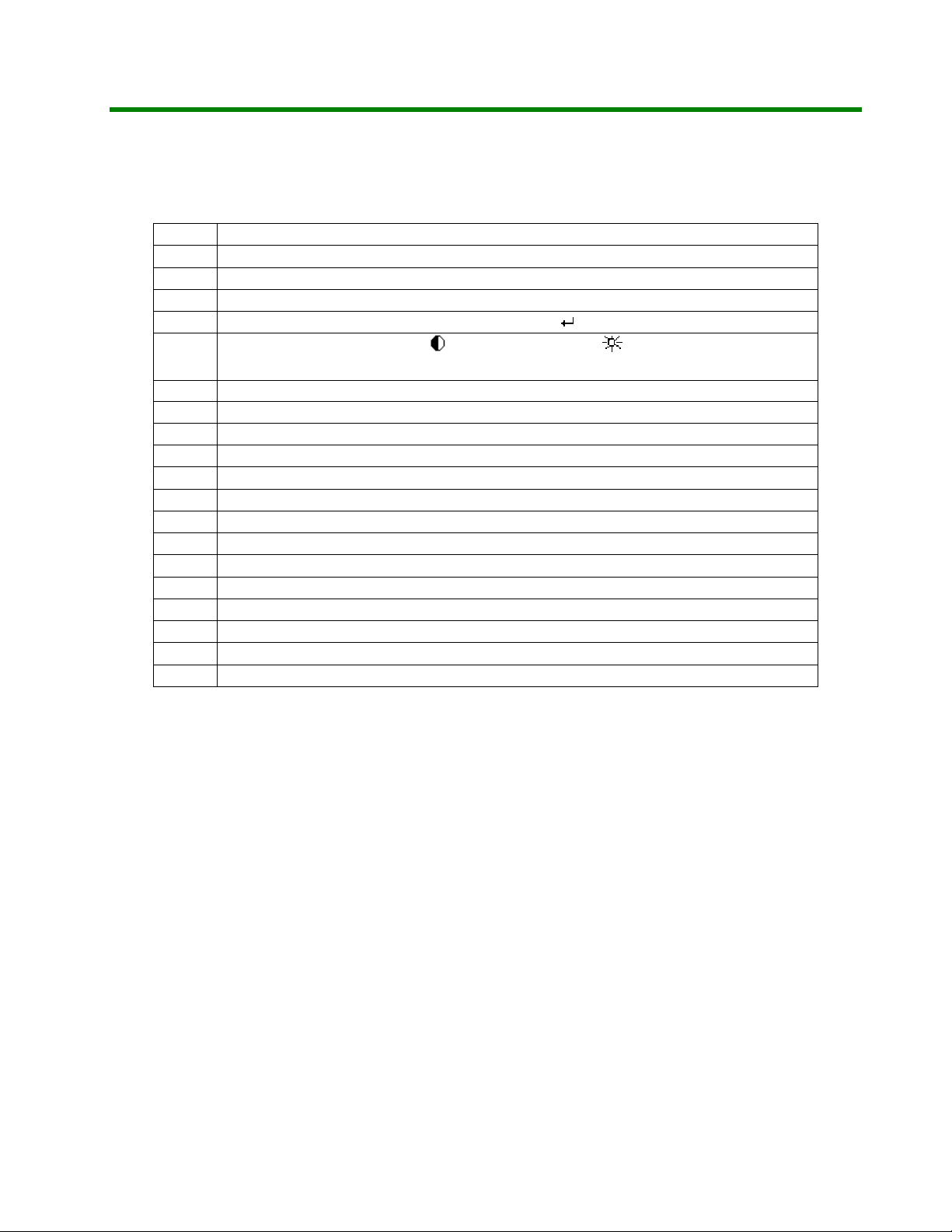
3.6 User Controls and Indicator
3.6.1 Power ON/OFF Switch
3.6.2 LED Indicator
3.6.3 OSD
3.6.3.1 Buttons
3.6.3.2 OSD Menu Level
3.6.4 Hot Keys Function
3.6.4.1 Contrast (
3.6.4.2 Brightness (
*3.6.4.3 Mute On (
*3.6.4.4 Mute Off (
*3.6.4.5 In monitor power saving mode
Table 2 S962A OSD Control Map
)
)
)
)
The switch control scaler power down and turn off panel.
The LED color shall indicate power status as shown in
paragraph 3.7
ESC ,▽, △,
See Table 2. S962A OSD Control Map
Press “△ ” to pop up ;then press “△ ” or “▽ ” to adjust Contrast
up or down.
Press “▽ ” to pop up ;then press “△ ” or “▽ ” to adjust
Brightness up or down.
Press “Esc” directly to disable speakers, while speakers in
normal state.
Press “Esc” directly to enable speakers, while speakers in
audio mute state.
“Esc” key is for Mute On and Off function
“△ ” key is for increasing volume function.
“▽ ” key is for decreasing volume function.
“ESC” key is disable or enabling audio mute.
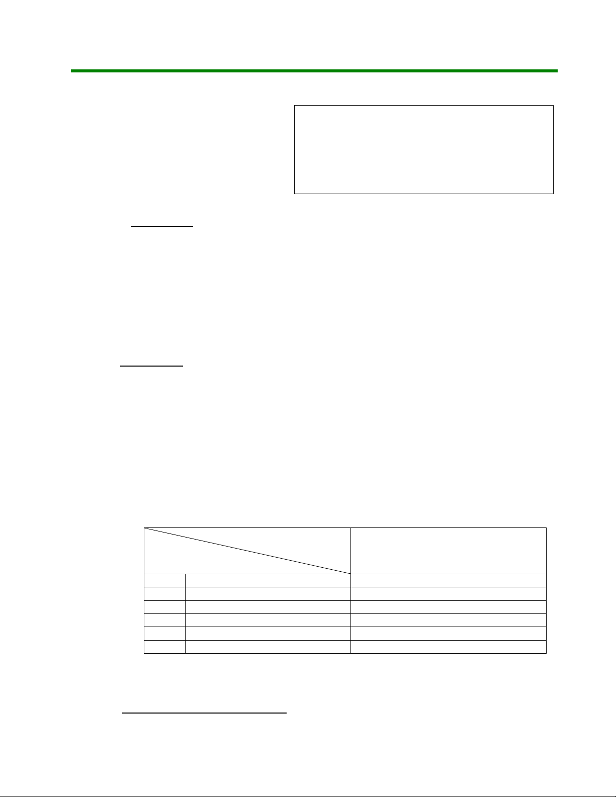
1.VGA-D15 input:
Level 1 Level 2 Level 3 Level 4
Direct Adj Brightness
Direct Adj Contrast
Direct Adj Audio Mute
Main Menu
Volume Adjustment scale
Auto Tune
Color
Auto Colo
9300° K
9
Page 10

C
r
)
)
)
)
)
r
T
X
C
T
X
C
T
X
S962A
3.6.5 Accessory OSD Indications
Image
Language
OSD Position
Reset Yes/No
Signal out of range An input signal which is outside the range defined in
6500° K
Use
Clock Adjustment scale
Phase Adjustment scale
H-Position Adjustment scale
V-Position Adjustment scale
Smooth On/Off
English(select
German(select
French(select
Spanish(select
Italian(select
H-Position Adjustment scale
V-Position Adjustment scale
Cente
Section 3.4 shall cause the monitor to display a message
Signal Out of Range.
R/G/B select Adjustment scale
Service Manual
No Signal Input and power down.
3.7 Power Management
This monitor will meet the low power specification, Including USA governmental requirements
For Energy Star, the NUTEK standard and the VESA DPMS standard which detected the Hori. /Vert.
Sync signal from host CPU.
A dual color (green/amber) LED is located on the front bezel to indicate the power management
states.
Status
Sync. Video
Active Active 43W max. On - Green
Power
consumption
When the signal cable is not plugged into PC or when the
horizontal or vertical sync are absent and when the
monitor is turned on. After 5 sec isn’t to detect H or V Sync
then show “No Signal Input” for 5 seconds and then show ”
Power down” message on screen 2 sec. And then the
monitor shall go to power saving status. If first turn on the
monitor, shows “No Signal Input” 30 sec.
Power
management
Picture Recovery time LED Color
No Sync. Blanked
Note. 1 : Audio function is operating at no signal input.
≦ 2W
(Note.1)
Power saving
≦ 3 sec
Amber
Once “Esc” or “△ ” or “▽ ” key initiates under power saving condition, the audio function
an be waked up and the power consumption can not be the above definition.
10
Page 11

C
T
X
C
T
X
C
T
X
S962A
4. TROUBLE SHOOTING
4.1 Main Procedure
Service Manual
11
Page 12

C
T
X
C
T
X
C
T
X
S962A
St ar t
Power On
Service Manual
Is indicator light?
Yes
I s back li ght on?
Yes
Display performance OK?
Yes
O.S.D. Adjustment OK?
No
No
No
No
4.2 Power Circuit
T r ouble shoot ing
4.3 No Back li ght
Tr ouble shooting
4.4 Perf or mance
Tr ouble shooting
4.5 O.S.D.
Tr ouble shooting
Yes
Audio Function OK?
Yes
No Tr ouble Found
End
4.2 Power Circuit Trouble Shooting
No
4.6 Audio
T r ouble shoot ing
12
Page 13

C
T
X
C
T
X
C
T
X
S962A
St ar t
Change AC power cord
and r etr y
NG
Service Manual
Change
power boar d
and r etr y
NG
Change
display board
and r etr y
No Tr ouble Found
No
OK
End
Back to 4.1
Main Procedure
Yes
End
4.3 Backlight Trouble Shooting
13
Page 14

C
T
X
C
T
X
C
T
X
S962A
St ar t
Change
power boar d
and r etr y
NG
Service Manual
Change
mai n boar d
and r etr y
NG
Change
LCD panel
and r etr y
No Tr ouble Found
No
OK
End
Back to 4.1
Main Procedure
Yes
End
4.4 Performance Trouble Shooting
14
Page 15

C
T
X
C
T
X
C
T
X
S962A
St art
Service Manual
Screen mi ssi ng color Ch ange V GA cabl e Chan ge mai n b oar d
NO
Block on screen Change main board Ch ange L CD p anel
NO
Li ne on screen Change main board
NO
Screen is flickering
NO
NG NG
OK OK
NGNG
OK OK
NG NG
Ch ange L CD p anel
OK OK
NG NG NG
Change power board Ch ang e m ai n boar d Change LCD panel
OK OK OK
Scr een wh i te
NO
noise & line bar
No trouble found
Scr een w i t h
End
Check panel
connector
NG NG
Press enter button call OSD
menu try reset or auto ture
OK OK
NG NGNG
Check main
board connector
OKOK OK
Change LCD panel
Change main board
15
Page 16

C
T
X
C
T
X
C
T
X
S962A
4.5 O.S.D. Trouble Shooting
St art
Pr ess f unc ti o n k ey
Service Manual
No OSD menu
No contrast or bright
adj menu
No troubl e found
End
NG NG
NG NG
Change display board
and r et ry
Change display board
and r et ry
OK OK
Ch ange mai n bo ard
and r et ry
OKOK
Ch ange mai n bo ard
and r et ry
16
Page 17

C
T
X
C
T
X
C
T
X
S962A
4.6 Audio Trouble Shooting
St art
Mark sure audio
cable i s OK .
Service Manual
No sound
Sound broken
Volume can’t
Adjust
NG NG
Ch ange speak er
NG
NG
Ch ange speak er
OK
Change main board
and r et ry
OK
Ch ange mai n bo ard
and r et ry
OKOK
No troubl e found
End
17
Page 18

C
T
X
C
T
X
C
T
X
S962A
PARTS LIST
ITEM PART NUMBER DESCRIPTION
1 AC1921-B01 MAIN PCBA
2 DC1921-B01 POWER PCBA
3 GC1921-B01 DISPLAY PCBA
4 10A19-1A2A LCD TFT 1280*1024 AU
5 SSBASE-508 SUB ASSY BASE
6 04007983000H CARTON
7 05101668000H HOLDER (R)
8 05101678000H HOLDER (L)
Service Manual
9 05Z0001900E PLASTIC HANDLE BAR
10 05Z0002900E PLASTIC CLAP BOARD
11 06208061000H USER MANUAL
12 65B70-1801ZH CABLE AUDIO
13 98T111-P62 DISKETTE 3.5IN 1.44M
14 65S10-150CZH CABLE SIGNAL
18
Page 19

C
T
X
C
T
X
C
T
X
S962A
Service Manual
19
 Loading...