

Page 1
SERVICE MANUAL
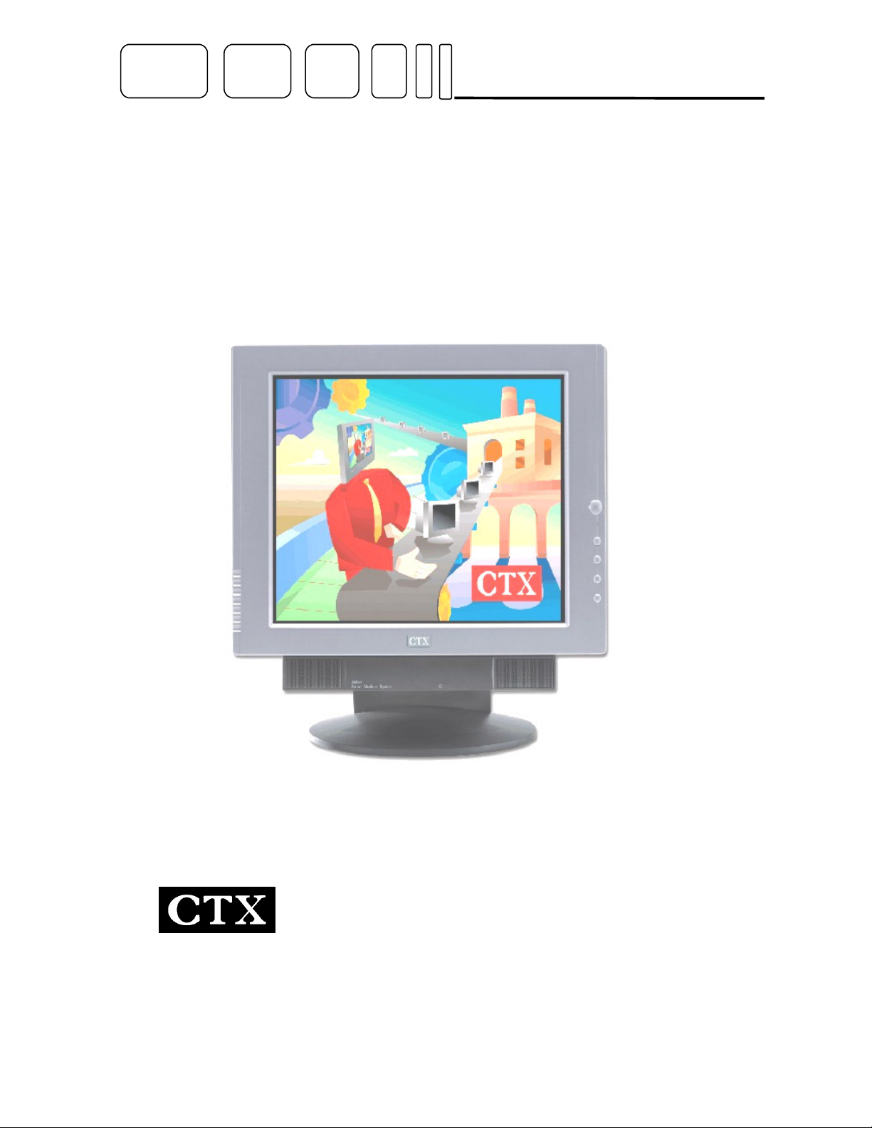
PV722i/PV722E
The Monitor Specialists
EDITION 1
JAN. 2003
Page 2

C
T
X
C
T
X
C
T
X
Service Manual
TABLE OF CONTENTS
CONTENTS PAGE
Sections
1. Scope (For PV722i) 3
2. Input requirements (For PV722i) 3~ 5
3. Electrical Characteristics (For PV722i) 5~11
4. Scope (For PV722E) 12
5. Input requirements (For PV722E) 13
6. Electrical Characteristics (For PV722E) 15~22
7. Trouble Shooting 23~24
PV722i/PV722E
8. System Block Diagram 25
9. Inverter Board I/O Connection 26
10. IC Pin Configuration 27~30
11. Pin Assignment 31~36
12. Parts List 37
Appendix
1. Main Board Circuit Diagram
2. Assembly Explosion Drawing
-1-
Page 3

C
T
X
Service Manual
PV722i /PV722E
Copyright © 2002 by Chuntex Electronic Co., Ltd.
The CTX SERVICE MANUAL is published by Chuntex Electronic Co., Ltd
All rights reserved. No part of this manual may be used, copied, reproduced, or transmitted in any form or by any
means for any purpose without the express written permission of the publisher.
The publisher has been trying its best to make this publication perfect, and in this manner takes no responsibility for
the use of any of the materials or methods described in this manual, or for the products thereof. Neither will the
publisher be responsible for any damages caused by misuse or misquotation.
C
C
T
T
X
X
Information in this manual is subject to change by the publisher without any notice in advance.
CTX is a registered trademark of Chuntex Electronic Co., Ltd.
-2-
Page 4
C
y
p), ▽(
T
X
C
T
X
C
T
X
The Specification of PV722i
1. SCOPE
This specification defines the design and performance requirements for the 17” SXGA TFT LCD display
monitor.“PV722i “
There are 3 models of “ PV722i” in each own’s project code.
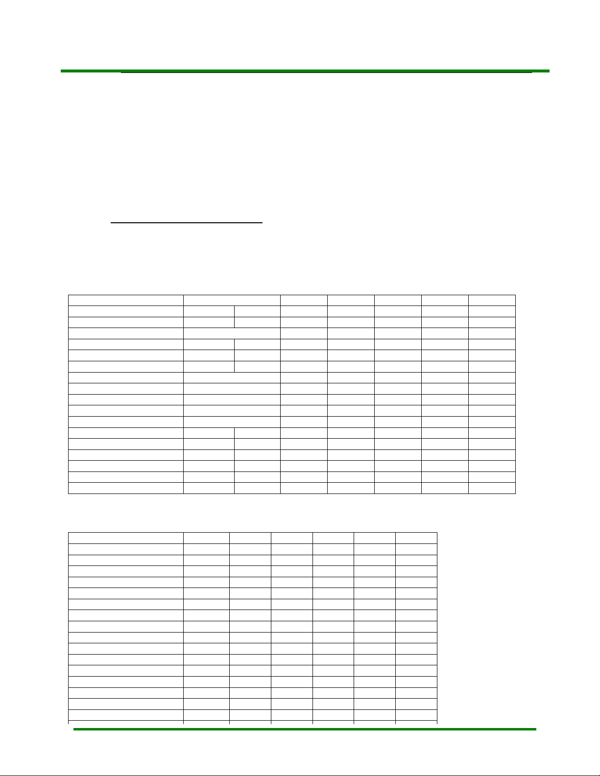
Project Code: The common features of the 3 models of “PV722i” are listed in the following table:
Feature Description
1 Universal input AC/DC Adaptor
2 Digital Visual interface (DVI-D) TMDS 1 Ch 165MHz
3 Analog RGB interface (VGA ) 30~80KHz, 59~75Hz, 135MHz
4 17” SXGA 1280*1024 multi-view-angle (MVA), TFT LCD panel
5
Function ke
6
Direct Acess function keys : △ for
7 Green/Amber LED indicator for power on/power saving
8 Plug & play support with DDC2B protocol installed.
9 Power saving mode compliant with Energy Star
10 OSD (on screen display) MENU operation
10.1 Brightness adjustment
10.2 Contrast adjustment
10.3 Auto tune function (VGA)
10.4 Color selection
10.5 Image adjustment
10.6 Position adjustment
10.7 Language selection
10.8 Reset function
10.9 Source selection (DVI/VGA)
11 OSD information of input status
12 Panel Rotation function for Portrait Graphic Application
The differential features of the 3 models of PV722i are listed in the following table
Feature
ISO 13406-2
Audio Modual (speaker*2,Stero earphone jack) No No Yes
Direct “ESC” key for Audio mute No No Yes
Volume Adjustment(OSD) No No Yes
2. INPUT REQUIREMENTS
2.1 Input Power
2.1.1. Power Source
2.1.2. Power Consumption
s * 6 : Power On/Off, ESC, △(u
contrast function, ▽ for brightness function
Model
Project
View Direction Class
Pixel Faults Class
110 Vac, 240 Vac, + -10%, 50/60 Hz (48W,2.5ψ plug)
1.PV722I model with Audio (LKC17SS2CC01)
Normal operating mode : ≦ 43W
Power saving mode
a. Audio module is operating at full power(max) : ≦ 9W
b. Audio module is operating at no signal input (max) : ≦ 5W
Power switch off : ≦ 3W (PC off)
-3-
PV722i
(ISO13406-2
Class Ⅱ)
LKC17SS2CC
down), (enter),signal source
PV722i
(ISO13406-2
Class Ⅱ , 0 pixel Fault)
LKC17SS0CC
Service Manual
PV722i/PV722E
PV722i
(ISO13406-2
Class Ⅱ + Audio)
LKC17SS2CC01
Page 5
Service Manual
PV722i /PV722E
C
T
X
C
C
T
T
X
X
2.1.3. AC Line Drop Out
2.1.4. AC Wave Distortion
2.1.5. In-rush Current
2.1.6. Power Cord
2.1.7 DC Power cable
2.2 Display Input
2.2.1. Analog Input RGB Video
2.2.1.1 Sync Signal
Analog Input Connection a. Detachable Mini D-sub 15 pin male in two ends signal
b. A female Mini D-sub 15 pin base .
Pin 1 Red
2.2.2 Digital Input
Input Interface DVI-D V.1 TMDS 165MHz 1-Channel
Digital Input connection a. Detachable DVI-D male connector in two ends signal cable:
b. A female DVI-D connector in monitor side.
2. PV722I model without Audio (
LKC17SS0CC)
Normal operating mode : ≦ 40W
Power saving mode : ≦ 3W
Power switch off : ≦ 3W (PC off)
Picture must not disappear while AC 100 V input drop out(10ms, 100%)
10% max. permitted
50 A max at 230 Vac cold start
Detachable, 3P with ground type.
Detachable from display unit and captive with AC/DC adapter.
Analogue, 0.0 to 0.7 V peak to peak
Separate RGB
Input impedance 75 Ohm
Positive polarity
Separate horizontal & vertical sync (3.3V & 5V)
Low level 0.8 V maximum
High level 2.0 V minimum
Positive or negative polarity
cable.
Pin 2 Green
Pin 3 Blue
Pin 4 No Connection
Pin 5 Ground
Pin 6 R Return
Pin 7 G Return
Pin 8 B Return
DVI-D 1-Channel Pin Assignment
+
+
LKC17SS4CC /LKC17SS2CC/
Pin 9 D-SUB-5V
Pin 10 Ground
Pin 11 Ground
Pin 12 SDA
Pin 13 H. Sync &
Composite sync
Pin 14 V. Sync
Pin 15 SCL
+
+
+
-
-4-
Page 6
C
T
X
C
T
X
C
T
X
Service Manual
PV722i/PV722E
2.3 Audio Input (LKC17SS2CC01)
2.3.1 Audio Input Signal Right &Left channels.
Input level : 1Vrms(typ), 2Vrms(max)
Input Impedance : 15Kohm
2.3.2 Audio Input Connection a. Detachable stereo phone head in two ends signal cable.
b. A female stereo phone jack base.
3. ELECTRICAL CHARACTERISTICS
3.1 LCD Panel
3.1.1. Type 17” diagonal, SXGA resolution, color TFT-LCD
3.1.2. Pixel structure
3.1.3. Gray scale 16 million colors.
3.1.4. Surface treatment 3H hard coating ,anti-static,anti-glare
3.1.5. Backlight
3.1.6 Pixel Faults
R/G/B sub-pixels in vertical stripes
1280 x 1024 array matrix
a- Si TFT active matrix (MVA)
Integral CCFT ,
Type to support field replacement.
Life time 30000 hours @ 25C, 50% of initial value.
Model
Pixel Faults type
Type1 Bright Pixels (Note 2)
Type2 Dark Pixels (Note 3)
Type3 Fault Pixels / Sub-Pixels(Note 4)
Type4 Cluster of type1 or type 2 faults(Note 5)
Type5 Cluster of type3 faults (Note5)
Type6 Total Pixel Faults
-5-
PV722i
≦ 5 ≦ 3
≦ 5 ≦ 3
≦ 3 ≦ 5
≦ 2 ≦ 0
≦ 3 ≦ 3
≦ 8 ≦ 5
PV722i
(ISO13406-2
Class Ⅱ)
PV722i
(ISO13406-2
Class Ⅱ
+ 0 pixel Fault)
0
0
0
0 0
0
0
PV722i
(ISO13406-2
Class Ⅱ+ Audio)
≦ 3
≦ 3
≦ 5
≦ 3
≦ 5
Page 7
μ
S ( Bac
C
T
Service Manual
PV722i /PV722E
Note 1 : The spec meets ISO/FDIS 13406-2 Pixel Faults Class Ⅱ requirements.
Note 2 : Bright pixels in full black pattern.
Note 3 : Dark pixels in full white pattern
Note 4 : fault Pixel / Sub-Pixel : The pixel or sub-pixel is abnormal but not bright/dark pixel.
Note 5 : Fault Cluster : Two or more Pixels/Sub-pixels with faults within 5 * 5 block of pixels.
3.2 Modes and Timing Compability
3.2.1 Analog
Table 1. Supported Timing
VESA Standard mode :
Display Format IBM VGA VESA VESA VESA VESA VESA
Horizontal Dots 720 640 640 640 800 800 800
Vertical lines 400 480 480 480 600 600 600
Horizontal Frequency ( KHz) 31.469 37.861 37.5 37.879 48.077 46.875
Vertical Frequency ( Hz ) 70 59.94 72.809 75 60.317 72.188 75.000
Pixel Rate ( MHz ) 28.322 25.175 31.5 31.5 40 50 49.5
H. Sync. Polarity - - - - + + +
A μS ( Period )
B μS ( Pulse Width )
C
D μS ( Active Area )
E μS (Front Porch )
V. Sync. Polarity + - - - + + +
O ms ( Period ) 16.683 13.735 13.333 16.579 13.853 13.333
P ms ( Pulse Width ) 0.064 0.079 0.080 0.106 0.125 0.064
Q ms ( Back Porch ) 1.048 0.739 0.427 0.607 0.478 0.448
R ms ( Active Area ) 12.711 15.253 12.678 12.800 15.840 12.480 12.8
S ms ( Front Porch ) 0.318 0.237 0.027 0.026 0.770 0.021
k Porch )
31.778 26.413 26.667 26.4 20.8 21.333
25.422 20.317 20.317 20.0 16.0 16.162
3.813 1.270 2.032 3.2 2.4 1.616
1.907 4.063 3.810 2.2 1.28 3.232
0.636 0.763 0.508 1.00 1.12 0.323
X
C
T
X
C
T
X
Display Format VESA VESA VESA VESA VESA VESA
Horizontal Dots 1024 1024 1024 1152 1280 1280
Vertical lines 768 768 768 864 1024 1024
Horizontal Frequency ( KHz) 48.363 56.746 60.023 67.5 63.981 79.976
Vertical Frequency ( Hz ) 60.004 70.069 75.029 75 60.013 75.025
Pixel Rate ( MHz ) 65.0 75 78.75 108 108 135
H. Sync. Polarity - - + + + +
A μS ( Period )
B μS ( Pulse Width )
C μS ( Back Porch )
D μS ( Active Area )
E μS (Front Porch )
V. Sync. Polarity - - + + + +
O ms ( Period ) 16.666 14.272 13.238 13.333 16.663 13.329
P ms ( Pulse Width ) 0.124 0.106 0.050 0.044 0.047 0.038
Q ms ( Back Porch ) 0.6 0.513 0.466 0.474 0.594 0.475
R ms ( Active Area ) 15.88 13.599 12.795 12.8 16.006 12.804
20.667 17.707 16.660 14.815 15.631 12.504
2.092 1.813 1.219 1.185 1.180 1.067
2.462 1.920 2.235 2.370 2.065 1.837
15.754 13.653 13.003 10.667 11.797 9.481
0.369 0.321 0.203 0.593 0.590 0.119
-6-
Page 8
C
T
X
C
T
X
C
T
X
Service Manual
PV722i/PV722E
VGA Support Mode
1280 * 1024 @ 70Hz
1280 * 1024 @ 72Hz
1280 * 960 @ 60Hz,70Hz,72Hz,75Hz
1208 * 720 @ 60Hz
1152 * 864 @ 60Hz, 70Hz,72Hz
1024 * 768 @ 72Hz
800 * 600 @ 70Hz
640 * 480 @ 70Hz
640 * 350 @ 70Hz
Fig. 1 Timing chart
VIDEO
H SYNC
B C D E
Video
V Sync
P Q R S
o
3.2.2 Digital
DVI Support mode
640 * 480 @60Hz
800 * 600 @60Hz
1024*768 @60Hz
-7-
Page 9
Service Manual
PV722i /PV722E
3.3 Plug & Play
DDC 2B data transmission only for I
3.4 Scanning characteristics
Refresh rate 59Hz to 75Hz 59Hz to 61Hz
3.5 Audio Module (Optional , for LKC17SS2CC01 model)
3.6 User Controls and Indicator
3.6.1 Power ON/OFF Switch
3.6.2 LED Indicator
3.6.3 OSD
3.6.3.1 Buttons
3.6.3.2 OSD Menu Level
3.6.4 Hot Keys Function
3.6.4.1 Contrast (
3.6.4.2 Brightness (
*3.6.4.3 Mute On (
*3.6.4.4 Mute Off (
*3.6.4.5 In monitor power saving mode
3.6.4.6 Signal source key Press “ESC” key is for Mute ON and OFF function directly.
Remark : “*” : for LKC17SSCC01 model.
Horizontal frequency 30KHz to 80KHz 30KHz to 66KHz
2.2.1 Input Level : 1Vrms(typ),2Vrms(max)
2.2.2 Output Power : 1W * 2 (10% THD,1KHz)
2.2.3 Total Harmonic Distortion (THD)…..0.3%(0.5W*2, 1KHz)
2.2.4 Frequency Response ± 3dB : 330 ~ 20KHz
VESA DDC 2B, DVI support DDC 2B+ standard
)
)
)
)
VGA DVI
The switch control scaler power down and turn off panel.
The LED color shall indicate power status as shown in paragraph
3.7
ESC ,▽ , △ , ,Signal source
See Table 2. PV722 OSD Control Map
Press “△ ” to pop up ;then press “△ ” or “▽ ” to adjust Contrast up or
down.
Press “▽ ” to pop up ;then press “△ ” or “▽ ” to adjust Brightness up
or down.
Press “Esc” directly to disable speakers, while speaker in normal
state.
Press “Esc” directly to enable speakers, while speaker in audio
mute state.
“Esc” key is for Mute On and Off function
“△ ” key is for increasing volume function.
“▽ ” key is for decreasing volume function.
Press “Signal source” key to select VGA or DVI input.
C
T
2
C BUS interface card.
X
C
T
X
C
T
X
-8-
Page 10
C
T
X
C
T
X
C
T
X
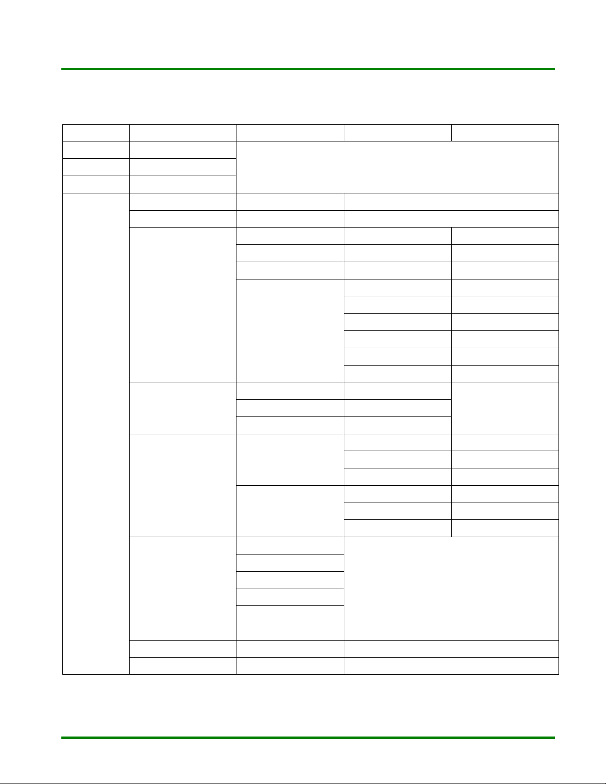
Table 2 PV722 OSD Control Map
1. VGA-D15 input
Level 1 Level 2 Level 3 Level 4
Detect Adj. Brightness
Detect Adj. Contrast
Detect Adj. *Audio Mute
Service Manual
PV722i/PV722E
Main Menu
*Volume Adjustment Scale
Auto Tune Adjustment Scale
Color
Image
Position
9300∘K
6500∘K
User R/G/B select Adjustment Scale
Moive
Clock Adjustment Scale
Phase Adjustment Scale
Smooth On/Off
Image Position
OSD Position
Color Adjustment Scale
Tint Adjustment Scale
Flesh Tone Adjustment Scale
(Y) Brightness Adjustment Scale
(Y) Contrast Adjustment Scale
Reset
H-Position Adjustment Scale
V-Position Adjustment Scale
Center Adjustment Scale
H-Position Adjustment Scale
V-Position Adjustment Scale
Center Adjustment Scale
Language
Reset Yes/No
Source DVI/VGA (select)
English (select)
German (select)
French (select)
Spanish (select)
Italiano (select)
中文 (option)
-9-
Page 11
Service Manual
PV722i /PV722E
Remark : “*” : for LKC17SS2CC01 model
2.DVI input
Level 1 Level 2 Level 3 Level 4
Detect Adj. Brightness
Detect Adj. Contrast
Detect Adj. *Audio Mute
Main Menu
*Volume Adjustment Scale
Color
Image Smooth On/Off
Position
Language
9300∘K
6500∘K
User R/G/B select Adjustment Scale
Moive
OSD Position
English (select)
German (select)
French (select)
Spanish (select)
Italiano (select)
Color Adjustment Scale
Tint Adjustment Scale
Flesh Tone Adjustment Scale
(Y) Brightness Adjustment Scale
(Y) Contrast Adjustment Scale
Reset
H-Position Adjustment Scale
V-Position Adjustment Scale
Center Adjustment Scale
C
T
X
C
T
X
C
T
X
Reset Yes/No
Source DVI/VGA (select)
Remark : “*” : for LKC17SS2CC01 model.
3.6.5 Accessory OSD Indications
Signal out of range An input signal which is outside the range defined in
No Signal Input and power
down
中文 (option)
Section 3.4 shall cause the monitor to display a message
Signal Out of Range.
When the signal cable is not plugged into PC or when the
horizontal or vertical sync are absent and when the
monitor is turned on. After 5 sec isn’t to detect H or V Sync
then show “No Signal Input” 3 sec, and then show ” Power
down” message on screen 2 sec.
If first turn on the monitor, shows “No Signal Input” 30 sec.
-10-
Page 12
C
T
X
C
T
X
C
T
X
3.7 Power Management
Note 1 : For LKC17SS2CC, LKC17SS0CC model.
Note 2 : For LKC17SS2CC01 model:
Once “Esc” or “△ ” or “▽ ” key initiates under power saving condition, the audio function
can
be woken up and the power consumption can not be the above definition.
This monitor will meet the low power specification, Including USA governmental requirements
For Energy Star, the NUTEK standard and the VESA DPMS standard which detected the Hori. /Vert.
Sync signal from scaling IC (gm-5020).
A dual color (green/amber) LED is located on the front bezel to indicate the power management
states.
Sync Power consumption
On 43W max. (LKC17SS2CC01)
40W max. (LKC17SS2CC00) (Note 1)
Off
≦ 5W (LKC17SS2CC01) (Note 2)
≦ 3W (LKC17SS2CC0) (Note 1)
Power
management
ON - Green
Off
Service Manual
Picture Recovery time LED Color
≦ 3 sec
PV722i/PV722E
Amber
-11-
Page 13

p
g
g
(
VGA)
p
(
)
g
)
Service Manual
PV722i /PV722E
The Specification of PV722E
1. SCOPE
This specification defines the design and performance requirements for the 17” SXGA TFT LCD
display monitor.“PV722E “
There are 2 models of “ PV722E” in each own’s project code.
Project Code: The common features of the 2 models of “PV722E” are listed in the following table :
Feature Description
1
Universal in
2
Di
ital Visual interface (DVI-D)TMDS 1 Ch 165MHz
3
Analo
4
17” SXGA 1280*1024 MVA, TFT LCD
5
6
Direct Acess function keys : △ for
7 Green/Amber LED indicator for power on/power saving
8 Plug & play support with DDC2B protocol installed.
9 Power saving mode compliant with Energy Star
10 OSD (on screen display) MENU operation
10.1 Brightness adjustment
10.2 Contrast adjustment
10.3 Auto tune function (VGA)
10.4 Color selection
10.5 Image adjustment
10.6 Position adjustment
10.7 Language selection
10.8 Reset function
10.9
Source selection
11 OSD information of input status
12 Panel Rotation function for Portrait Graphic Application
13
USB 2.0 HUB
14
15
Audio Module inte
16 Direct “Esc” key for Audio mute
17 Volume adjustment
The differential features of the 2 models of PV722E are listed in the following table
Feature
ISO13406-2 Pixel Faults Class
ut AC/DC Adaptor
RGB interface
*
DVI/VGA
rated (speaker * 2, stereo earphone jack
30~80KHz, 59~75Hz, 135MHz
Model
project
anel
contrast function, ▽ for brightness function
LKC17SS2CC03 LKC17SS0CC03
-12-
△
▽
PV722E PV722E
Ⅱ Ⅰ
C
T
X
( 0 pixel Fault )
C
C
T
T
X
X
Page 14

C
T
X
C
T
X
C
T
X
2. INPUT REQUIREMENTS
2.1 Input Power
2.1.1. Power Source
2.1.2. Power Consumption
For PV722E model (Audio + USB)
Normal operating mode 1.Audio Module and USB Hub are operating at full power
Power saving mode 1. USB Hub is operating at full power, the number of active
Power switch off 1. USB Hub upstream port isn’t connected to PC or PC off. ≦ 2W
2.1.3. AC Line Drop Out
2.1.4. AC Wave Distortion
2.1.5. In-rush Current
2.1.6. Power Cord
2.1.7 DC Power cable
2.2 Display Input
2.2.1. Analog Input RGB Video
2.2.1.1 Sync Signal
Analog Input Connection a. Detachable Mini D-sub 15 pin male in two ends signal
2.USB Hub all ports aren’t connected to any device, and
the audio module is operating at full power.
3. USB Hub all ports aren’t connected to any device,and
2. USB Hub all ports aren’t connected to any device, audio
3. USB Hub all ports aren’t connected to any device, audio
Ports is 4 with 0.5A per port. Audio module is operating
At full power.
module is operating at full power.
module is operating at no audio signal input.
100 ~ 240 Vac, + -10%, 50/60 Hz (60W,2.5ψ plug to monitor;
1.7ψ plug to USB hub)
Picture must not disappear while AC 100 V input drop out
(10ms, 100%)
10% max. permitted
50 A max at 240 Vac cold start
Detachable, 3P with ground type.
Detachable from display unit and captive with AC/DC
adapter.
Service Manual
PV722i/PV722E
≦ 57W
≦ 44W
≦ 40W
≦ 25W
≦ 9W
≦ 4W
Analogue, 0.0 to 0.7 V peak to peak
Separate RGB
Input impedance 75 Ohm
Positive polarity
Separate horizontal & vertical sync (3.3V & 5V)
Low level 0.8 V maximum
High level 2.0 V minimum
Positive or negative polarity
-13-
Page 15

Service Manual
PV722i /PV722E
2.3 Audio Input
2.4 USB Input (AS0USB-001) USB Rev.2.0
2.4.1 USB Input signal Differential signal D+,D-
2.4.2 USB Input connection a. Detachable standard USB cable (2.0)
b. A female standard USB up-stream port base.
c. A 1.7φ DC power jack
2.4.3 USB Output Connection Four female USB down-stream port bases.
3. ELECTRICAL CHARACTERISTICS
3.1 LCD Panel
b. A female Mini D-sub 15 pin base .
Pin 1 Red
2.2.2 Digital Input
Input Interface DVI-D V.1 TMDS 165MHz 1-Channel
Digital Input connection a. Detachable DVI-D male connector in two ends signal cable
b. A female DVI-D connector in monitor side.
Pin Signal Assignment Pin Signal Assignment Pin Signal Assignment
1 T.M.D.S Data 2- 9 T.M.D.S Data 1- 17 T.M.D.S Data 0-
2 T.M.D.S Data 2+ 10 T.M.D.S Data 1+ 18 T.M.D.S Data 0+
3 T.M.D.S Data 2 Shield 11 T.M.D.S Data 1 Shield 19 T.M.D.S Data 0 Shield
4 NC 12 NC 20 NC
5 NC 13 NC 21 NC
2.3.1 Audio Input Signal Right & Left channels.
2.3.2. Audio Input Connection a. Detachable stereo phone head in two ends signal cable.
DVI-D 1-Channel Pin Assignment
cable.
Pin 2 Green
Pin 3 Blue
Pin 4 No Connection
Pin 5 Ground
Pin 6 R Return
Pin 7 G Return
Pin 8 B Return
Input level : 1Vrms(typ), 2Vrms(max)
Input Impedance : 15 Kohm
b. A femal stereo phone jack base.
-14-
Pin 9 D-SUB-5V
Pin 10 Ground
Pin 11 Ground
Pin 12 SDA
Pin 13 H. Sync &
Composite sync
Pin 14 V. Sync
Pin 15 SCL
C
T
X
C
C
T
T
X
X
Page 16

C
T
X
C
T
X
C
T
X
Service Manual
PV722i/PV722E
3.1.1. Type 17” diagonal, SXGA resolution, color
TFT-LCD
3.1.2. Pixel structure
R/G/B sub-pixels in vertical stripes
1280 x 1024 array matrix
a-Si TFT active matrix (MVA)
3.1.3. Gray scale 16 million colors.
3.1.4. Surface treatment
3.1.5. Backlight
3.1.6 Pixel Faults
Pixel Faults Type
Type1
Type2
Type3
Type4
Type5
Type6
Bright Pixels(Note2)
Dark Pixels(Note3)
Fault Pixels / Sub-Pixels(Note4)
Cluster of type1 or type 2 faults(Note
5) 22faults(Note5)
Cluster of type3 faults (Note5)
Total Pixel Faults
3H hard coating ,anti-static,anti-glare
Integral CCFT ,
Type to support field replacement.
Life time 30000 hours @ 25C, 50% of initial
value.
Model
PV722E (Note1)
( 0 Pixel Fault )
0
0
0
PV722E (Note 6)
≦ 3
≦ 3
≦ 5
0 0
0
0
≦ 3
≦ 5
Note 1 : The spec meets ISO/FDIS 13406-2 Pixel Faults Class I requirements.
Note 2 : Bright pixels in full black pattern.
Note 3 : Dark pixels in full white pattern
Note 4 : fault Pixel / Sub-Pixel : The pixel or sub-pixel is abnormal but not
bright/dark pixel.
Note 5 : Fault Cluster : Two or more Pixels/Sub-pixels with faults within 5 * 5
block of pixels.
Note 6 : The spec meets ISO/FDIS 13406-2 Pixel Fault Class Ⅱ requirements.
3.2 Modes and Timing Compability
-15-
Page 17

C
Service Manual
PV722i /PV722E
3.2.1 Analog
Table 1. Supported Timing
VESA Standard mode :
Horizontal Dots 720 640 640 640 800 800 800
Vertical lines 400 480 480 480 600 600 600
Horizontal Frequency
( KHz) 31.469 37.861 37.5 37.879 48.077 46.875
Vertical Frequency ( Hz ) 70 59.94 72.809 75 60.317 72.188 75.000
Pixel Rate ( MHz ) 28.322 25.175 31.5 31.5 40 50 49.5
H. Sync. Polarity - - - - + + +
A μ S ( Period )
B μ S ( Pulse Width )
C μ S ( Back Porch )
D μ S ( Active Area )
E μ S (Front Porch )
V. Sync. Polarity + - - - + + +
O ms ( Period ) 16.683 13.735 13.333 16.579 13.853 13.333
P ms ( Pulse Width ) 0.064 0.079 0.080 0.106 0.125 0.064
Q ms ( Back Porch ) 1.048 0.739 0.427 0.607 0.478 0.448
R ms ( Active Area ) 12.711 15.253 12.678 12.800 15.840 12.480 12.8
S ms ( Front Porch ) 0.318 0.237 0.027 0.026 0.770 0.021
Horizontal Dots 1024 1024 1024 1152 1280 1280
Vertical lines 768 768 768 864 1024 1024
Horizontal Frequency 48.363 56.746 60.023 67.5 63.981 79.976
Vertical Frequency ( Hz ) 60.004 70.069 75.029 75 60.013 75.025
Pixel Rate ( MHz ) 65.0 75 78.75 108 108 135
H. Sync. Polarity - - + + + +
V. Sync. Polarity - - + + + +
O ms ( Period ) 16.666 14.272 13.238 13.333 16.663 13.329
P ms ( Pulse Width ) 0.124 0.106 0.050 0.044 0.047 0.038
Q ms ( Back Porch ) 0.6 0.513 0.466 0.474 0.594 0.475
R ms ( Active Area ) 15.88 13.599 12.795 12.8 16.006 12.804
S ms ( Front Porch ) 0.062 0.054 0.017 0.015 0.016 0.012
The monitor shall support an internal scaler to enable the monitor to display lower resolution
video modes. The scaler shall convert all lower resolution modes up to 1280x1024. The
monitor shall support all the modes listed in Table 1.
Display Format IBM VGA VESA VESA VESA VESA VESA
Display Format VESA VESA VESA VESA VESA VESA
31.778 26.413 26.667 26.4 20.8 21.333
25.422 20.317 20.317 20.0 16.0 16.162
20.667 17.707 16.660 14.815 15.631 12.504
2.092 1.813 1.219 1.185 1.180 1.067
2.462 1.920 2.235 2.370 2.065 1.837
15.754 13.653 13.003 10.667 11.797 9.481
0.369 0.321 0.203 0.593 0.590 0.119
3.813 1.270 2.032 3.2 2.4 1.616
1.907 4.063 3.810 2.2 1.28 3.232
0.636 0.763 0.508 1.00 1.12 0.323
T
C
T
C
T
X
X
X
-16-
Page 18

C
T
X
C
T
X
C
T
X
Service Manual
PV722i/PV722E
VGA Support Mode
1280 * 1024 @ 70Hz
1280 * 1024 @ 72Hz
1280 * 960 @ 60Hz,70Hz,72Hz,75Hz
1208 * 720 @ 60Hz
1152 * 864 @ 60Hz, 70Hz,72Hz
1024 * 768 @ 72Hz
800 * 600 @ 70Hz
Fig.1 Timing Chart
Video
Video
V Sync
P Q R S
3.2.2 Digital
DVI Support mode
640 * 480 @60Hz
800 * 600 @60Hz
1024*768 @60Hz
-17-
Page 19

Service Manual
PV722i /PV722E
C
T
X
C
C
T
T
X
X
3.3 Plug & Play VESA DDC 2B, DVI support DDC 2B+ standard
DDC 2B data transmission only for I
3.4 Scanning characteristics
Horizontal frequency 30KHz to 80KHz 30KHz to 66KHz
Refresh rate 59Hz to 75Hz 59Hz to 61Hz
3.5 USB 2.0 Module (AS0USB-001)
The USB 2.0 Hub can detect the status of Host Computer (USB V
or turn off it, to reach the purpose of saving power.
It have three conditions to active the USB Hub power(the green light will turn on).
1) 60W adaptor power on and plug-in the USB 2.0 Hub.
2) Plug-in the USB cable between host computer and USB 2.0 Hub.
3) Turn on PC power (then PC start boot up and into Windows Platform properly.)
3.5.1 Input power 12V (Self power mode only)
3.5.2 Down stream port output power 5V ± 5% ( > 4.75V, < 5.25V)
3.5.3 Overcurrent detection : 0.6 to 1.25A ( 0.9A typ.) (The USB standard defines the max.
current is 0.5A for each port)
3.5.4 Bus transation : High speed(480Mbps), full speed(12Mbps), low
speed(1.5Mbps)
3.6 Audio Module(LKC17SS2CC03)
2.2.1 Input Level : 1Vrms(typ),2Vrms(max)
2.2.2 Output Power : 1W * 2 (10% THD,1KHz)
2.2.3 Total Harmonic Distortion (THD)…..0.3%(0.5W*2, 1KHz)
2.2.4 Frequency Response ± 3dB : 330 ~ 20KHz
VGA DVI
BUS
2
C BUS interface card.
power) to turn on the USB Hub
-18-
Page 20

C
T
X
C
T
X
C
T
X
3.4 User Controls and Indicator
3.7.1 Power ON/OFF Switch
3.7.2 LED Indicator
3.7.3 OSD
3.7.3.1 Buttons
3.7.3.2 OSD Menu Level
3.7.4 Hot Keys Function
3.7.4.1 Contrast (
3.7.4.2 Brightness (
3.7.4.3 Mute On (
)
)
Service Manual
PV722i/PV722E
The switch control scaler power down and turn off
panel.
The LED color shall indicate power status as shown
in paragraph 3.7
ESC ,▽, △, ,Signal source
See Table 2. PV722 OSD Control Map
Press “△ ” to pop up ;then press “△ ” or “▽ ” to adjust
Contrast up or down.
)
Press “▽ ” to pop up ;then press “△ ” or “▽ ” to adjust
Brightness up or down.
Press “Esc” directly to disable speakers, while
speaker in normal state.
3.7.4.4 Mute Off (
)
3.7.4.5 In monitor power saving
mode
Press “Esc” directly to enable speakers, while speaker
in audio mute state.
“Esc” key is for Mute On and Off function
“△ ” key is for increasing volume function.
“▽ ” key is for decreasing volume function.
3.7.4.6 Input source change Change between VGA and DVI mode.
-19-
Page 21

Service Manual
PV722i /PV722E
Table 2 PV722 OSD Control Map
1. VGA-D15 input
Level 1 Level 2 Level 3 Level 4
Detect Adj. Brightness
Detect Adj. Contrast
Detect Adj. Audio Mute
Main Menu
Volume Adjustment Scale
Auto Tune Adjustment Scale
Color
Image
Position
Language
9300∘K
6500∘K
User R/G/B select Adjustment Scale
Moive
Clock Adjustment Scale
Phase Adjustment Scale
Smooth On/Off
Image Position
OSD Position
English (select)
German (select)
French (select)
Spanish (select)
Italiano (select)
Color Adjustment Scale
Tint Adjustment Scale
Flesh Tone Adjustment Scale
(Y) Brightness Adjustment Scale
(Y) Contrast Adjustment Scale
Reset
H-Position Adjustment Scale
V-Position Adjustment Scale
Center Adjustment Scale
H-Position Adjustment Scale
V-Position Adjustment Scale
Center Adjustment Scale
C
T
X
T
T
X
X
C
C
中文 (option)
Reset Yes/No
Source DVI/VGA (select)
-20-
Page 22

C
T
X
C
T
X
C
T
X
2.DVI input
Level 1 Level 2 Level 3 Level 4
Detect Adj. Brightness
Detect Adj. Contrast
Detect Adj. Audio Mute
Service Manual
PV722i/PV722E
Main Menu
Volume Adjustment Scale
Color
Image Smooth On/Off
Position
Language
9300∘K
6500∘K
User R/G/B select Adjustment Scale
Moive
OSD Position
English (select)
German (select)
French (select)
Color Adjustment Scale
Tint Adjustment Scale
Flesh Tone Adjustment Scale
(Y) Brightness Adjustment Scale
(Y) Contrast Adjustment Scale
Reset
H-Position Adjustment Scale
V-Position Adjustment Scale
Center Adjustment Scale
Spanish (select)
Italiano (select)
中文 (option)
Reset Yes/No
Source DVI/VGA (select)
3.7.5 Accessory OSD Indications
Signal out of range An input signal which is outside the range defined in
No Signal Input and power
down
-21-
Section 3.4 shall cause the monitor to display a message
Signal Out of Range.
When the signal cable is not plugged into PC or when the
horizontal or vertical sync are absent and when the
monitor is turned on. After 5 sec isn’t to detect H or V Sync
then show “No Signal Input” 3 sec, and then show ” Power
down” message on screen 2 sec.
If first turn on the monitor, shows “No Signal Input” 30 sec.
Page 23

Service Manual
PV722i /PV722E
3.8 Power Management
This monitor will meet the low power specification, Including USA governmental requirements
for Energy Star, the NUTEK standard and the VESA DPMS standard which detected the Hori. /Vert.
sync signal from host CPU.
A dual color (green/amber) LED is located on the front bezel to indicate the power management states.
C
T
X
C
C
T
T
X
X
Sync Power consumption Power management Picture Recovery time LED Color
On 57W max. (LKC17SS2CC03) ON - Green
Off
Once “Esc” or “△ ” or “▽ ” key initiates under power saving condition, the audio function can be
woken up
and the power consumption can not be the above definition.
Note1 : USB Hub under power saving mode (or all ports aren’t connected to any device), audio
module is
operating at no audio signal input.
≦ 4W (Note 1)
Off
≦ 3 sec
Amber
-22-
Page 24

C
T
X
C
T
X
C
T
X
7. TROUBLE SHOOTING
VIDEO DOES NOT APPEAR
Service Manual
PV722i/PV722E
-23-
Page 25

Service Manual
PV722i /PV722E
R.G.B is not displayed correctly
C
T
X
C
C
T
T
X
X
-24-
Page 26

C
T
X
C
T
X
C
T
X
Service Manual
PV722i/PV722E
8. SYSTEM BLOCK DIAGRAM
-25-
Page 27

Service Manual
PV722i /PV722E
9. INVERTER BOARD I/O CONNECTIONS
C
T
X
C
C
T
T
X
X
-26-
Page 28

C
T
X
C
T
X
C
T
X
10. IC Pin Configuration
Service Manual
PV722i/PV722E
-27-
Page 29

Service Manual
PV722i /PV722E
C
T
X
C
C
T
T
X
X
-28-
Page 30

C
T
X
C
T
X
C
T
X
Service Manual
PV722i/PV722E
-29-
Page 31

Service Manual
PV722i /PV722E
C
T
X
C
C
T
T
X
X
-30-
Page 32

C
T
X
C
T
X
C
T
X
11. Pin Assignment MAIN/BOARD
PIN
MODE
1280*1024 80K/75Hz 0 0 0 0 4.15 4.14 4.66 4.66
1024*768 56K/70Hz 0 0 0 0 4.15 4.14 4.66 4.66
IC U1 (AT24C02)
1 2 3 4 5 6 7 8
TEST CONDITION : AC LINE IN: 110V/60Hz
PATTEN:FULL WHITE
Uint:Volt
Service Manual
PV722i/PV722E
IC U6 (FDS6912A)
PIN
MODE
1280*1024 80K/75Hz 5.04 10.72 2.52 4.45 3.33 3.33 5.06 5.06
1024*768 56K/70Hz 5.04 10.72 2.52 4.43 3.33 3.33 5.07 5.07
1 2 3 4 5 6 7 8
IC U8 (AT24C02)
PIN
MODE
1280*1024 80K/75Hz 0 0 0 0 4.87 4.71 0 4.78
1024*768 56K/70Hz 0 0 0 0 4.87 4.73 0 4.79
1 2 3 4 5 6 7 8
IC U12 (AT24C16)
PIN
MODE
1280*1024 80K/75Hz 0 0 0 0 5.07 5.07 0 5.07
1024*768 56K/70Hz 0 0 0 0 5.07 5.07 0 5.07
1 2 3 4 5 6 7 8
IC U13 (LM358DR)
PIN
MODE
1280*1024 80K/75Hz 10.63 3.04 3.31 0 0.73 0.72 10.96 11.79
1024*768 56K/70Hz 10.63 3.04 3.31 0 0.73 0.71 10.63 11.80
1 2 3 4 5 6 7 8
-31-
Page 33

Service Manual
PV722i /PV722E
IC U14 (W78E65)
PIN
MODE
1280*1024 80K/75Hz 5.07 5.07 5.07 5.08 5.07 5.07 0.04 5.07 0.02 0
1024*768 56K/70Hz 5.07 5.07 5.07 5.07 5.07 5.07 0.04 5.08 0.02 0
IC U14 (W78E65)
PIN
MODE
1280*1024 80K/75Hz 4.90 5.07 4.71 5.07 4.25 5.07 5.07 0.03 0.03 2.16
1024*768 56K/70Hz 4.90 5.07 4.73 5.07 4.25 5.07 5.07 0.03 0.03 2.16
IC U14 (W78E65)
PIN
MODE
1280*1024 80K/75Hz 2.18 0 5.08 5.08 5.07 4.77 0.02 0.04 4.31 5.07
1024*768 56K/70Hz 2.18 0 5.08 5.07 5.07 4.77 0.02 0.04 4.30 5.07
1 2 3 4 5 6 7 8 9 10
11 12 13 14 15 16 17 18 19 20
21 22 23 24 25 26 27 28 29 30
C
C
C
T
T
T
X
X
X
IC U14 (W78E65)
PIN
MODE
1280*1024 80K/75Hz 4.01 5.07 1.60 5.07 5.07 0.26 3.33 2.49 2.86 0.80
1024*768 56K/70Hz 4.01 5.07 1.60 5.07 5.07 0.76 3.33 2.50 2.86 0.78
IC U14 (W78E65) U15 (AP431R)
PIN
MODE
1280*1024 80K/75Hz 0.92 0.88 1.08 5.07 4.44 0 2.51
1024*768 56K/70Hz 0.89 0.96 1.22 5.07 4.42 0 2.51
IC U16 (THC63LVDM83A)
PIN
MODE
1280*1024 80K/75Hz 3.33 2.42 2.42 1.27 0 1.20 1.34 2.42 3.33 2.42
1024*768 56K/70Hz 3.34 2.59 2.59 1.36 0 1.67 1.18 2.59 3.33 2.59
31 32 33 34 35 36 37 38 39 40
41 42 43 44 E C B
1 2 3 4 5 6 7 8 9 10
-32-
Page 34

C
T
X
C
T
X
C
T
X
Service Manual
PV722i/PV722E
IC U16 (THC63LVDM83A)
PIN
MODE
1280*1024 80K/75Hz 1.32 1.50 0 2.42 1.67 2.42 0 2.42 2.27 2.38
1024*768 56K/70Hz 1.53 1.62 0 2.59 1.62 2.59 0 2.59 2.40 2.49
11 12 13 14 15 16 17 18 19 20
IC U16 (THC63LVDM83A)
PIN
MODE
1280*1024 80K/75Hz 0 2.37 0.14 2.42 0 3.33 0.21 0.22 0 2.42
1024*768 56K/70Hz 0 2.43 0.21 2.59 0 3.33 0.21 0.22 0 2.59
21 22 23 24 25 26 27 28 29 30
IC U16 (THC63LVDM83A)
PIN
MODE
1280*1024 80K/75Hz 1.55 3.33 0 3.33 0 0 1.31 1.21 1.28 1.23
1024*768 56K/70Hz 1.55 3.33 0 3.33 0 0 1.31 1.21 1.28 1.23
31 32 33 34 35 36 37 38 39 40
IC U16 (THC63LVDM83A)
PIN
MODE
1280*1024 80K/75Hz 1.21 1.29 0 3.33 1.23 1.27 1.21 1.28 0 2.42
1024*768 56K/70Hz 1.21 1.29 0 3.33 1.23 1.25 1.21 1.28 0 2.59
41 42 43 44 45 46 47 48 49 50
IC U16 (THC63LVDM83A)
PIN
MODE
1280*1024 80K/75Hz 1.28 2.38 0 0.04 0 2.42
1024*768 56K/70Hz 1.13 2.38 0 0.04 0 2.59
51 52 53 54 55 56
-33-
Page 35

Service Manual
PV722i /PV722E
IC U17 (THC63VLDM83A)
PIN
MODE
1280*1024 80K/75Hz 3.33 2.42 2.42 1.06 0 0.72 0.93 2.42 3.33 2.42
1024*768 56K/70Hz 3.33 2.59 2.59 1.21 0 0.99 1.06 2.59 3.33 2.59
IC U17 (THC63VLDM83A)
PIN
MODE
1280*1024 80K/75Hz 0.97 1.71 0 2.42 1.34 2.42 0 2.42 2.17 2.24
1024*768 56K/70Hz 1.26 1.75 0 2.59 1.39 2.59 0 2.59 2.24 2.40
1 2 3 4 5 6 7 8 9 10
11 12 13 14 15 16 17 18 19 20
C
C
C
T
T
T
X
X
X
IC U17 (THC63VLDM83A)
PIN
MODE
1280*1024 80K/75Hz 0 2.24 0.32 2.42 0 3.33 0.22 0.22 0 2.42
1024*768 56K/70Hz 0 2.49 0.35 2.59 0 3.33 0.22 0.22 0 2.59
IC U17 (THC63VLDM83A)
PIN
MODE
1280*1024 80K/75Hz 1.54 3.33 0 3.33 0 0 1.31 1.21 1.28 1.22
1024*768 56K/70Hz 1.54 3.33 0 3.33 0 0 1.33 1.21 1.28 1.22
IC U17 (THC63VLDM83A)
PIN
MODE
1280*1024 80K/75Hz 1.21 1.28 0 3.33 1.24 1.25 1.22 1.28 0 2.42
1024*768 56K/70Hz 1.21 1.28 0 3.33 1.24 1.23 1.22 1.28 0 2.59
21 22 23 24 25 26 27 28 29 30
31 32 33 34 35 36 37 38 39 40
41 42 43 44 45 46 47 48 49 50
-34-
Page 36

C
T
X
C
T
X
C
T
X
PIN
MODE
1280*1024 80K/75Hz 1.38 2.37 0 0.02 0.01 2.42
1024*768 56K/70Hz 1.22 2.43 0 0.02 0.01 2.59
IC U17 (THC63VLDM83A)
51 52 53 54 55 56
Service Manual
PV722i/PV722E
IC U18 (74F14D)
PIN
MODE
1280*1024 80K/75Hz 0.08 6.32 0.48 4.83 4.81 0.45 0 6.35 0 6.35
1024*768 56K/70Hz 4.95 0.18 4.43 0.51 0.51 3.98 0 5.17 0 5.16
1 2 3 4 5 6 7 8 9 10
IC U18 (74F14D)
PIN
MODE
1280*1024 80K/75Hz 0 0.15 6.32 5.07
1024*768 56K/70Hz 0 4.82 0.17 5.07
11 12 13 14
TR Q1 (2N3904) Q4 (2N3904) Q5 (MMBT3906LT1)
PIN
MODE
1280*1024 80K/75Hz 0 10.71 0 0 3.33 0 5.07 5.05 4.40
1024*768 56K/70Hz 0 10.73 0 0 3.33 0 5.07 5.05 4.40
E C B E C B E C B
TR Q7 (MMBT3906LT1) Q8 (MMBT3906LT1)
PIN
MODE
1280*1024 80K/75Hz 5.07 0 10.61 3.34 3.30 2.68
1024*768 56K/70Hz 5.07 0 10.95 3.34 3.30 2.68
E C B E C B
INVERTER
Unit : Volt
PIN
MODE
IC U1 (9435A)
1 2 3 4 5 6 7 8
-35-
Page 37

Service Manual
PV722i /PV722E
1280*1024 80K/75Hz 11.72 11.73 11.73 4.97 8.64 8.64 8.64 8.64
1024*768 56K/70Hz 11.74 11.74 11.74 5.04 8.58 8.58 8.58 8.58
IC U2 (9435A)
PIN
MODE
1280*1024 80K/75Hz 11.74 11.74 11.74 5.19 8.36 8.36 8.36 8.36
1024*768 56K/70Hz 11.73 11.73 11.73 5.11 8.43 8.43 8.43 8.43
IC IC1 (BA9741F32)
PIN
MODE
1280*1024 80K/75Hz 1.70 0.95 0.57 0.57 1.61 0.73 4.29 0 11.74 4.55
1024*768 56K/70Hz 1.70 0.95 0.57 0.57 1.61 0.72 4.34 0 11.75 4.58
1 2 3 4 5 6 7 8
1 2 3 4 5 6 7 8 9 10
C
C
C
T
T
T
X
X
X
IC IC1 (BA9741F32)
PIN
MODE
1280*1024 80K/75Hz 0.62 1.62 0.57 0.57 0.06 2.49
1024*768 56K/70Hz 0.61 1.62 0.57 0.57 0.06 2.49
TR QI (BRA114EMP) Q2 (BRA114EMP) Q3 (2SD2098)
PIN
MODE
1280*1024 80K/75Hz 11.75 11.75 0 0 0 3.71 0 8.59 -0.67
1024*768 56K/70Hz 11.75 11.75 0 0 0 3.71 0 8.65 -0.68
11 12 13 14 15 16
E C B E C B 3 2 1
TR Q4 (2SD2098) Q5 (2SD2098) Q6 (2SD2098)
PIN
MODE
1280*1024 80K/75Hz 0 8.5 -0.64 0 8.45 -0.65 0 8.65 -0.68
1024*768 56K/70Hz 0 8.47 -0.65 0 8.46 -0.65 0 8.66 -0.68
3 2 1 3 2 1 3 2 1
-36-
Page 38

C
T
X
C
T
X
C
T
X
Service Manual
PV722i/PV722E
TR Q7 (2N3904) Q8 (2N3904) Q9 (MMBT3906LT1)
PIN
MODE
1280*1024 80K/75Hz 4.90 11.73 4.93 5.08 11.75 5.19 4.89 0 4.93
1024*768 56K/70Hz 4.90 11.73 4.93 5.08 11.75 5.14 4.89 0 4.93
E C B E C B E C B
TR Q10 (MMBT3906LT1)
PIN
MODE
1280*1024 80K/75Hz 5.01 0 5.06
1024*768 56K/70Hz 5.01 0 5.09
E C B
-37-
Page 39

Service Manual
PV722i /PV722E
12. PARTS LIST
ITEM PART NUMBER DESCRIPTION
1 AC1720-D01 MAIN PCBA
2 DC1720-A03 POWER PCBA
3 EC1720-A01 INTERFACE A/V PCBA 17 INCH
4 TC1720-D01 INVERTER PCBA(CMO)
5 10A17-0C0A LCD TFT 1280*1024(M170E4-L02)
6 0800055367 CABINET BACK
7 0820094311 CABINET FRONT
8 SSBASE-418 SUB ASSY BASE
C
T
X
C
C
T
T
X
X
9 SZADPT-030P SUB-Z ASSY ADAPTER 48W(For PV722i)
10 SZADPT-101B SUB-Z ASSY ADAPTER 60W(For PV722E)
11 0400739300 CARTON 553*260*580
12 0510148800 HOLDER (R)
13 0510149800 HOLDER (L)
14 0670455000 LABEL CARTON (For PV722i)
15 0670456000 LABEL CARTON (For PV722i)
16 0670349500 LABEL CARTON (For PV722E)
17 0670452600 LABEL CARTON (For PV722E)
18 05Z0001900 PLASTIC HANDLE BAR
19 05Z0002900 PLASTIC CLAP BOARD
SMART MEDIUM SYSTEMSAB802 (For
20 AS00AV-009
PV722E)
21 AS0USB-001 ACCESSORIES USB MODEL (FOR PV722E)
-38-
 Loading...