

Page 1

CT
SYSTEMS I W A
VETEK
COMMUNICATIONS SERVICE MONITOR
THIS
DOCUMENT
INFORMATION
ANY
MANNER
CELLULAR
CONTAINS
IN
THIS
DOCUMENT
WITHOUT
CT
(TOLL
THE
SYSTEMS
BEECH
Telex#
OPERATION
MODEL
TESTER/SIMULATOR
INFORMATION
IS
Nar
PRIOR
{317)
FREE
(800)
217124
FAX#
APPROVAL,
P.O.
BOX
GROVE,
(U.S.A.)
787-5721
OUTSIDE
245-6356
317-788-4197
MANUAL
2500
PROPRIETARY
TO
BE
USED
IN
TOCT
OR
DUPLICATED
WRITING
I W A VETEK
470
IN. 461
OF
C T
SYS
07
INDIANA)
IND
UD
SYSTEMS.
BY
CT
SYSTEMS.
THE
IN
This equipment,
copyright
part,
the
exclusive
may
is
included
not
be
rights
or
part,
copied
of
includes software copyrighted
in
the
software. The software included
without
CT
violating
SYSTEMS I WA
the
copyright
VETEK.
in
1989 and
la.ws of
in
this
the
United
the
notice of
equipment.
States
this
or
and
9006
any
Page 2
CT
Systems
in
material
shipment.
any
warranty
assembly
for
defective
Wavetek
obligation
repairing
sole
opinion,
warranty
service
sole
changed
CT
Systems
surface
first
thirty
center.
discretion,
during
shipping
thirty
(30)
responsibility
F.O.B.
Should
he
will
surface
customer's
the
be
rate
I
Wavetek
and
workmanship
CT
Systems
or
a
90-day
under
any
normal
such
proves
when
returned
This
the
I
Wavetek
(30)
days,
for
customer
responsible
and
warrants
I
component
under
instrument
to
warranty
be
void
warranty
will
charges
days
CT
one-way
destination,
desire
for
the
higher
all
for
Wavetek
(except
period
use
this
after
during
warranty
which,
be
defective
to
the
may,
if
the
period.
assume
for
any
from
shipment
Systems
shipping
an
the ·difference
rate.
instruments
a
period
agrees
batteries,
shipping)
this
in
within
factory
at
-instrument
all
warranty
I
charges,
during
alternate
against
of
one
to
repair
period.
is
limited
CT
Systems
the
or
to
an
CT
Systems
ownership
responsibility
claims
date.
Wavetek
After
will
UPS
the
warranty
method
between
defects
year
or
replace
which
found
CT
Systems
solely
I
Wavetek
scope
authorized
I
Wavetek
for
during
the
surface,
period.
of
shipping,
the
after
are
to
in
be
to
of
the
is
UPS
the
first
assume
UPS
I
This
altered
not
warranty
by
in
accordance
Wavetek.
misuse,
repairs
improper
will
non-warranty
CT
Systems
products
either
Systems
or
Wavetek
purchase
which
This
implied,
alone
I
consequential
liability
price
a
claim
warranty
and
represent
connection
herein.
does
persons
If
the
be
program.
IWavetek
being
or
Wavetek
of
is
is
no
or
assume
with
not
not
authorized
with
instructions
instrument
repair,
billed
abnormal
as
assumes
used
in
in
conjunction
assumes
damages
for
breach
the
specific
made.
in
lieu
of
representative
for
CT
the
sale
of
apply
per
a
hazardous
no
liability
and,
of
all
Systems
our
to
any
by
CT
furnished
is
defective
conditions
the
no
responsibility
with
in
any
warranty
instrument
other
or
person
I
Wavetek
products
products
Systems
by
as
or
CT
Systems
or
dangerous
other
for
equipment.
secondary
event,
shall
shipped
warranties,
is
any
other
repaired
I
Wavetek
CT
Systems
a
result
operations,
I
Wavetek,
for
manner,
charges
CT
Systems
not
exceed
and
against
express
authorized
liability
than
set
or
or
I
of
its
CT
I
the
or
to
in
forth
Page 3
CONTENTS
SECTION 1 GENERAL
1.1
1.2
1.3
1.4
SECTION 2 PREPARATION
2.1
2.2
2.3
SECTION 3 OPERATION
3.1
INFORMATION
INTRODUCTION
CELLULAR
SERVICE
GENERAL
UNPACKING
POWER
ENVIRONMENTAL
INTRODUCTION
REQUIREMENTS
MODE
MONITOR
SPECIFICATIONS
FOR
SPECIFICATIONS
MODE
USE
AND
INSPECTION
CONSIDERATIONS
SPECIFICATIONS
3.2
3.3
3.4
FRONT-PANEL
FIGURE
FIGURE
CELLULAR
SERVICE
3-1.
3-2.
RADIO
MONITOR
DESCRIPTION
CONTROLS
REAR
TEST
MODE
AND
PANEL
MODE
APPLICATION
PORTS
OPERATION
NOTES
Page 4

SECTION-I
1.1
INTRODUCTION
The
CT
Systems
and
communications
use
package.
The Model
includes
a
testing.
test
results
connected.
A
manual
trouble
store
Testing
to
cell
control
mode
shooting
frequently
routines
site
messages;
frequency
Model
2500
is
"Go-No-Go"
A
parallel
can .be
enables
purposes.
used
include
calls;
and
deviation
2500
service
specially
automatic
printer
the
system
cell
mobile
is
a
cellular
monitor
designed
mode
port
generated
user
to
A
non-volatile
parameters.
cell
site
DTMF
site
voice
dialing;
measurements.
tester,
combined
for
is
provided
when
a
program
to
mobile
channel
into
for
cellular
quick
user
individual
memory
initiated
handoff;
voice
GENERAL
cell
one
cellular
so
a
hard
provided
allows
channel
INFORMATION
site
simulator
small,
testing
telephone
copy
printer
parameters
the
calls;
RF
power
SAT
easy
of
user
mobile
level
and
to
and
the
is
for
to
ST
Displays
ment
In
the
from
serial
Service
400
include
kHz
continuously
The
Model
audio
synthesizer
synthesizer
front-panel.
superimposed
oscilloscope
The
Model
volts,
audio
Power
power
Twenty
FM
frequency,
may
up
memory
front-panel
available
systems.
number)
Monitor
to
999.9999
variable
2500
contains
output
Deviation
on
in
both
2500
measures
deviation,
be
applied
to
110
registers
keyboard
software
mobile
and
and
has
the
demodulated
the
signal
error
to
watts
packages
dialed
station
Mode,
MHz
from
0.1
a 1 kHz
an
a
second
markers
Receive
and
frequency
the
(when
are
settings.
number;
class
the
in
100
uVolts
modulation
external
independently
and
displays
strength,
and
RF
in/out
terminated
available
An
allow
mark.
Model
Hz
to
modulation
at
output
Generate
sub-tone.
connector
optional
for
mobile
2500
steps.
10
source,
±5
kHz
for
SINAD
carrier
into
for
its
ID
generates
The
mVolts
variable
or
viewing
modes.
in
frequency,
for
a
storing
RS-232
use
number,
RF
in
a
10
input.
±600
dB
or
measuring
true
and
interface
in
ESN
and
output
five
ranges.
Hz
output
Hz
on
an
%
distortion,
demodulated
50
ohm
recalling
automated
(equip-
receives
leyel
to
10
The
audio
on
may
external
R.F.
load).
and
is
kHz
the
be
all
two
test
2500-MANUAL
PAGE
1 SECTION-1
Page 5

1.2
Generate
2500
CELLULAR
MODE
SPECIFICATIONS
RF
Frequency
Resolution:
RF
Output:
Accuracy:
Spectral
SAT
Frequencies:
Digital
Receive
RF
Frequency
Resolution:
Power
Range:
Accuracy:
Counter
Meter
Purity:
Control
Modes
Range:
Channels:
Range:
869
with
100
+2
+300
5.97,
824
30
0
+10%
to
channel
Hz
0.1
uv
dB
< -
35
0,1,2
to
kHz
to
4
of
894
45
MHz
spacing
to
dBc
kHz ·
6.00
and
849
watts,
Reading,
MHz
Duplex
100
(typically
of
center
and
3
MHz
(channels
uV
frequency
6.03
(channels
with
Internal
+1
offset
-
kHz
mW
001
50
001
and
dBc>
Load
to
to
30
1023)
KHz
1023)
Frequency
Resolution:
Accuracy:
ST
or
SAT
Resolution:
Accuracy:
FM
Measurements
FM
Deviation:
SAT
Deviation:
1.3
Generate
Freq
Resolution:
RF
Accuracy:
Spectral
2500
Range:
Output:
Error
SERVICE
Purity:
MONITOR
10
+200
1
+1
up
up
MODE
400
100
0.1
+2 dB
<-35
frequency
bands)
Hz
Hz
Hz
Hz
to
+17.85
to
+5
kHz
SPECIFICATIONS
kHz
to
kHz
999.9999
Hz
uV
to
10
mV
dBc
within
(within
(Typical
in
±300
<-50
MHz
5
ranges
all
dBc>
kHz
land
of
center
mobile
2500-MANUAL
PAGE
2
SECTION-1
Page 6

FM
Deviation:
Accuracy:
Ext
Mod:
Internal
Output
Reverse
Receive
Mod:
Impedance:
Power
Protection:
to
0
±5%
of
All
EIA
10
Hz
50
ohms
Auto
greater
in/out
20
kHz
FS
tones,
to
10
switch
than
connector
peak
kHz
to
approx.
10
Hz
internal
to
200
10
load
mw,
kHz
at
on
inputs
the
RF
Freq
Range:
Resolution:
Sensitivity:
Bandwidth:
Image
RF
Rejection:
Step
Subtone
Freq
Range:
Resolution:
Mod
Measurements
FH
Deviation:
Accuracy:
FM
Deviation
Freq
Counter
Range:
Counter
Markers:
Modes
400
kHz
100
Hz
10
uv @ 10
10
kHz
to
-50
dB
100
Hz
60
Hz
to
0.1
Hz
0
to
±20
of
±5%
±10%
FS @ 1 kHz
of
kHz
±600
Hz,
available>.
5 kHz
deviation.
to
999.9999
dB
SINAD,
20
kHz
270
Hz
kHz
FS @ 1 kHz
±5
kHz
Accuracy
MHz
typical
from
from
(optional
0
of
to
10
10
kHz
markers
kHz,
to
markers
±5%
20
@
RF
Freq:
Resolution:
Freq
Error:
Resolution:
Audio
Freq:
Resolution:
Power
Meter
Range:
Accuracy:
Display:
2500-MANUAL
30
MHz
1 kHz
10
Hz
10
Hz
10
Hz
1
Hz
0
to
110
watts
+10% FS
999.9999
Vacuum
PAGE
to
999.9999
to
10
kHz @ > 3.0
to
10
kHz
watts,
FS
to
600
MHz
Fluorescent
3
MHz
uv
rec.
auto
r~nging
MHz, +20% FS
signal
11
or
600
MHz
SECTION-1
110
to
Page 7

Internal
Freq
Range:
Resolution:
Output:
Fixed
Freq:
Accuracy:
Mod
Sources
10
Hz
0.1
1.0
to
0
1 kHz
Time
Hz,
Hz,
1.
Base
to
10
2 kHz
0
10
kHz
Hz
VRMS
±1
to
to
count
1999.9
10
kHz
Hz
Signal
Strength
Range:
Accuracy:
Display:
SINAD
Notch:
Range:
Resolution:
Accuracy:
Impedance:
Measurement
RF
100
Step
Hz
Size:
to
Memory
Stores
Memory
all
Size:
Voltmeter
<Rec.
Units:
999.9999
keyboard
20
Level)
MHz
steps
settings
registers.
60
dB
+3
dB
Vacuum
@1
kHz
to
0
dB
1
+1
dB
alOk
%
Distortion
in
each
(10
at
Fluorescent
30
dB
steps
at
ohms
register
uV
10
uV
12
dB (+3%
to
10
or
dB SINAD
for
mV>
at
system
25%)
storage.
Range:
Input
Impedance:
Accuracy:
Aging
Temp
1.4
Rate:
Stability
GENERAL
Operational
2500-MANUAL
(0
to
50
C):
SPECIFICATIONS
Temp
Range:
+20V DC,
:_lOOk
+5%
+1
+0.
0
ohms
of
ppm/year
2 ppm
to
50
PAGE
FS
20
C
4
VAC
peak,
up
to
50k
Freq
SECTION-I
Page 8

Power
Requirements:
AC
DC
Optional
able
Battery:
Internal
Recharge-
100/110/220/240
10.5
>12
to
Volt,
15.2
sealed
time
VDC
VAC
lead
±10%,
acid,
50-400
>lhr
cycles
run
Dimensions:
Weight
Standard
w/Battery:
Accessories
Options
10"x6.5"xl5.5"
<22
lbs.
Operation
Manual
Antenna
AC
Power
Parallel
Cellular
Service
Model
Cord
Printer
Test
Manual
300
trunking,
DCS
and
0.1
ppm
DTMF
TCXO
Port
Results
Encoder/Decoder
MTS, IMTS,
formats.
for
analog,
automated
with
digital,
2500-MANUAL
RS-232
Interface
RS-232
mode
Battery,
Protective
Accessories
cover)
Dust
Cover,
PAGE
Interface
12
Volt
Soft
Kit
for
5
for
Cellular
for
rechargable
Cover
(Including
front
panel
Service
Test
mode
Monitor
Front
SECTION-!
Dust
Page 9

2.1
UNPACKING
AND
INSPECTION
SECTION-2
PREPARATION
FOR
USE
Whe~
unpacking
instrument
material
The
control
operate
If
the
carrier
for
instrument
tests,
in
instrument
and
representative
your
2.2
instrument
POWER
the
instrument,
for
shipping
possible
was
then
accordance
received
your
will
CT
immediately
without
Indianapolis,
800-245-6356
REQUIREMENTS
damage.
future
inspected,
carefully
with
Section
has
Systems
waiting
CT
SYSTEMS I WAVETEK
5808
(317)
Churchman
787-5721
FAX
TELEX
inspect
Save
use.
given
packaged
been
Customer
arrange
for
(outside
(317)
the
the
final
3
of
damaged
damage
By-Pass
IN
46203-6109
(in
788-4197
217124
shipping
shipping
operational
for
this
manual.
in
Service
for
replacement
claim
Indiana)
Indiana)
container
carton
and
shipment,
transit,
representative.
or
settlements.
or
and
and
notify
repair
and
the
packing
quality
should
the
The
of
The
Hz
ground
primary
The
instrument
connection
instrument
an.optional
The
external
on
the
should
rear
be
potential
2.3
ENVIRONMENTAL
The
instrument
rear-panel
2500-MANUAL
power
12
DC
panel.
a
on
feet
operation
sources.
when
can
also
volt
source
Switchcraft
the
sleeve
CONSIDERATIONS
comes
also
is
selectable
The
it
is
be
operated
rechargable
should
The
plug
S-760
of
the
equipped
serve
as
three
connected
battery.
be
connected
(not
or
connector.
with
cord
wraps).
PAGE
for
100/120/220/240
conductor
to
the
from
11.8
to
supplied
equivalent
bottom
1 SECTION-2
proper
VDC
the
and
power
to
"EXT
with
with
rear-panel
cord
outlet.
15.2
the
VAC,
provides
VDC
+12
V
instrument>
the
feet
or
IN"
negative
50/60
with
jack
(the
a
'
J.
Page 10

The
instrument's
confined
The
instrument
degrees
instrument
working
C
and
is
small
spaces.
is
should
not
size
designed
be
restricted.
used
and
to
in
light
operate
an
area
NOTE
weight
between
where
permit
0
air
easy
degrees
flow
access
C
around
and
to
50
the
Exceeding
may
cause
the
upper
degraded
and
performance
lower
temperature
or
damage
limits
to
the
for
extended
instrument.
periods
2500-MANUAL
PAGE
2
SECTION-2
Page 11

3.1
INTRODUCTION
SECTION-3
OPERATION
This
Cellular
are
and
3.2
LED
audible
order
keys,
section
Tester/Simulator,
descriptions
3-2),
FRONT-PANEL DESCRIPTION
annunciators
CT
and
error
to
see
the
SYSTEMS I INC.
[l
_______
contains
of
notes
light
tone
identify
following
• I.
operating
Communications
the
front-
on
use
of
features.
to
indicate
sounds
the
if
the
instrument's
descriptions:
___...l]
The
instrument
ments.
Cellular
Monitor
Activates
K~Z
I
source
error
and
user
display
instructions
Service
rear-panels
an
active
makes
functions
settings
LED's
Test
mode
in
tone
of
the
generate
in
for
the
Monitor.
(refer
function
an
eCELLULAR
invalid
and
to
the
e SERVICE MONITOR
indicates
and
on
right
or
Service
operation.
1 kHz
mode.
receive.
modulation
annunciate
Sounds
Model
Figures
or
mode.
entry.
corresponding
TEST
pertinent
measure-
2500
Included
3-1
An
In
2500-MANUAL
AUDIO
SYNTH
•
·~
Activates
recently
frequency
Turns
Sounds
In
ted
phone
In"
on
Cellular
modulation
is
port.
PAGE
audio
set
frequency
in
Hz.
"Modulation
error
tone
Test
outputed
1
synthesizer
in"
in
receive.
Mode,
to
the
to
the
and
displays
port.
the
cellular
transmit-
"Modulation
at
most
tele-
SECTION-3
I
i.
Page 12

"!600Hz
± 5·
KHZ.
•
loEvl
~
Activates
or
markers
superimposed
display
in
±5
both
on
Rec.
markers
kHz
off.
an
&
deviation
on
external
Gen.
at
either
Markers
demod
modes.
±600
and
output
oscilloscope
shuts
Hz
are
for
ISINADI
I
voLTs
I
IWATTSI
8
Measures
The
SINAD
and
time
tone
Activates
volts.
SINAD/audio
mode
Measures
IN/OUT
Sounds
Measures
generated
displays
%
distortion
it
is
in
receive
and
port
error
SINAD
reading.
the
button
pressed.
either
Measures
in
RF
power
and
tone
FM
or
received
reading
and
displays
toggles
expressions
Sounds
mode.
D.C.
connector.
displays
in
deviation
between
an
volts
voltage
applied
generate.
RF
carrier
in
Hz.
reading.
each
error
or
A.C.
Displays
at
reading.
of
,
the
and
dB
at
RF
,--~--10
~GG
C!J~G
8IT1
2500-MANUAL
~
DATA
when
Sounds
ing
error
PAGE
KEYS.
preceded
an
error
is
made.
2
Inputs
by
tone
numerical
appropriate
when
programm-
data
key.
SECTION-3
Page 13

Terminates
Menu
routines
Selections.
numerical
in
Cellular
data.
Steps
Mode.
Executes
thru
Sub
IRFl
~
Displays
prefix
when
Steps
by
RF STEP
up
executes
key.
Steps
ceeded
setting
by
RECALL
used
Menu,
Sub
Routines
automatic
Addresses
SHIFT 6 ENTER -identifies
version.
RF
for
followed
RF
frequency
key.
RF
frequency
by
RF
down
key.
-to
step
advance
testing.
second
(Hold
step
changing
by
Steps
when
STEP
executes
thru
in
and
Enter
size
data
preceeded
In
to
functions.
.
and
up
stored
down
key.
when
Cellular
Cellular
Manual
continue
Key
Serves
RF
ENTER
when
when
Steps
Mode
to
as
step
by
preceeded
view)
size
key.
preceded
setting
RECALL
pre-
stored
Mode,
Test
thru
during
software
a
SHIFT
with
SHIFT
L.
0.
low
side
above
SHIFT
some
feres
SHIFT
signal
In
Cellular
will
change
To
select
the
PASS/FAIL
key.
.
ENTER
preset
REC
fre·quency
50MHz
function
readings
with
Watts-
strength.
select
tables
data.
injection
the
a
specific
-
loads
alternates
between
or
below
may
if
desired
Measures
Test
the
press
MODE
be
an
Mode,
PASS/FAIL
press -the
storage
the
high
for
955MHz.
necessary
L.O.
frequency.
and
the
"SHIFT"
table
receiver
side
frequencies
The
for
spur
Shift
inter-
displays
Shift
MODE.
and
leave
"ENTER"
key.
RAM
and
To
2500-MANUAL
PAGE
3 SECTION-3
Page 14

Prefix
ISTOREI
front-panel
memory
address
the
for
(should
code
'ENTER'
storing
keyboard
1
through
key).
be
and
displaying
settings
followed
20
and
in
by
then
RE-
CALL I
1
rsuB-1
~
fCllil
~
EJ·
EJ·
Prefix
keyboard
(should
0
through
key).
non-alterable
the
Counts
receive
Discontinues
operation
Menu
cellular
to
cellular
These
or
receive
activated
responds
mode
quency.
selected,
In
LED
squelch
signal.
Cellular
return
mode.
for
be
factory.
and
mode.
(see
test
two
by
and
When
the
receive
illuminates
is
If
it
recalling
settings
followed
20
and
Address
setting
displays
Service
and
displays
Section
routines
test
keys
the
Test
select
mode.
at
a
addressing
displaying
the
LED
broken
the
to
from
by
then
0
programmed
Monitor
Cellular
menu.
Only
time.
generate
is
mode
intrument
mode,
the
the
only
by
service
front-panel
memory
address
the
contains
sub
tone
3.3)
and
the
one
Each
the
frequency
the
illumi~ated.
associated
when
a
is
these
code
'ENTER'
Mode
Test
Aborts
returns
generate
mode
key
RF
fre-
mode
the
received
in
the
keys
monitor
at
in
of
is
is
a
2500-MANUAL
~
c=J
ORF
<ttERROR
9AF
In
the
receive
counter
In
generate
SINAD/AUDIO IN
and
Orr~
counter
when
the
RF
must
reprogramming
PAGE
for
modes
also
sufficient
IN/OUT
be
4
the
works
mode
RF,
connector
port.
de-activated
the
this
ERROR,
counter
are
power
selectable.
in
RF
frequency.
selects
AF
monitors
and
the
WATTS
is
keyed
The
or
count
the
OFF.
the
the
AF
1~e
mode
into
mode
when
SECTION-3
Page 15

j"RFl
~
extmv
eX.ImV
eXIO,uV
eXI}JV
eX
.l,uV
Selects
RF
generator.
receive.
one
of
five
Sounds
level
error
ranges
tone
for
in
_____
The
OPTION
following
LOW
VOLTAGE
•
CHG
rnml
(R,P.)
is
OPER
provided
Lights
voltage
Determines
front-panel
OPERATE
switch
instrument.
CHARGE
charging
when
Q!!.
with
.
-
-
the
the
battery
to
indicate
the
power
allows
to
front-panel
activate
only
circuit
allows
option:
function
switch.
front
to
be
power
low
panel
the
the
activated
switch
____
battery
of
battery
the
power
entire
_
is
j
..:
When
Model
the
2500-MANUAL
the
battery
front
2500,
panel
other
charging
OJ
OJ
power
than
circuit
switch
the
fuse,
is
Microprocessor
If
data
because
2500
default
steps:
{1)
seconds
and
turn
PAGE
off.
of
can
condition
Turn
Down
the
is
is
entry
system
be
unit
5 SECTION-3
off,
active.
unit
{3)
keys
no
circuitry
This
Reset
is
lock-up,
returned
by
off
Depress
simultaneously
on.
not
the
means
the
to
following
<2>
both
in
the
that
possible
Model
factory
Wait
the
and
5
Up
Page 16

l
lcHz
control
Audio
Synthesizer
deviation
deviation
control
I
-r-
CT
S'I'STOoiS,
----...r.rl""\''--
~
IIC.
MOOEI.
r
:1
EXT
DISPLAY
2-SOO
TSINA~I
1:1
DEV
r~---;
4
5
7
8 9
I I I
I
•
6
<!)
-
1
~
-
+
•
..
1 STORE 1
I
-
c~
I
sua
TONE
I AF
GEN
REI:
L£VEL
0
CEU..I.LI.A
0 SOMCE IIIONI10fl
'EM
AEC
50..ELCH
LOW BATT
l.
2.
J.
0
.
..
TnT
RF
output
~
RF
input
Duplex
. .
in
in
in
qenerate.
receive
Cellular
.
Speaker
voluae
Squelch
!or
for
selected
and
control.
level
receive
watts.
aode.
ra.nqe.
l.
2.
Audio
Powers
is
set
cha.rqed.
Powers
switch
Synthesizer
instrument
to
•operate•.
only
is
ba.ttery-cha.rqinq
aet
to
FIGURE
for
output.
for
operation
Battery
"cha.rqe•.
3-l.
when
(optional)
circuit
2500
Deaodulation
qenerate.
either
rear-panel
is
when
rear-panel
CONTROLS
Input
and
aode.
switch
trickle
(or
AF
output
Harkers
AND
SINAD,
count
in
can
input.
PORTS
volta.qe
in
receive,
be
superiaposed
qenerate.
Audio
aeaaureaent
Modulation
on
this
output
output
in
in
2500-MANUAL
PAGE
6
SECTION-3
Page 17

H~el/Serial
p
Humber
plate
Parallel
!or
autoaat~
Test
Results
Printer
Port
Cellular
Ch&r~e/Operator
battery
•odes:
option
1.
Allows
switch
b&ttery-charqinq
2.
Allows
switch
in
selects
the
~tch
the
to
the
to
instruaent.
provided
one
front
activate
front
activate
with
o!
two
-
panel
power
ONLY
circuitry.
panel
power
ALL
circuitry
·
±15
Volt
!or
triqqerinq
external
horizontal.
the
·
siqna:
.
scope
FIGURE
3-2.
Primary
Power
2500
Input
REAR
·
FUse\Line
PANEL
EXT+I2VDC
Voltaqe
Select
Ezternal
-
+12
voc
Optional
interface
input
RS-232
port.
.
•
2500-MANUAL
PAGE
7
SECTION-3
Page 18

3.3
CELLULAR
RADIO
TEST
MODE
l
SECTION-3
OPERATION
This
Cellular
site,
and a manual
U.S.
This
include:
section
Test
and
domestic
section
3.3.1
3.3.2
of
the
manual
Mode.
to
provide
control
public
of
CELLULAR
Cellular
PROGRAM .PARAMETERS
Summary
Programming
Programming
Programming
Programming
Programming
Programming
Programming
Programming
Programming
Programming
Programming
Programming
Programming
The
comprehensive
mode,
cellular
the
manual
TEST
Table
describes
Model-2500
for
cellular
mobile
is
divided
MENU
Test
Menu
of
PASS/FAIL
System
SAT
Digital
ESN
Forward
Last
Hand
Format
Initial
DTMF
Hook-Flash
Receiver
Test
the
is
testing
telecommunications
Flowchart
Parameter
ID
Color
Control
Voice
Voice
Off
Increment
Test
Sensitivity
Results
operation
designed
in
telephones
into
Defaults
Table
Code
Channel
Channel
Channel
Test
Printout
both
eight
of
to
simulate
an
automatic
that
subsections
the
Model-2500
comply
system.
a
with
cell
mode,
the
that
·
3.3.3
3.3.4
3.3.5
3.3.6
3.3.7
3.3.8
PRINT TEST RESULTS
AUTOMATIC
Automatic
Test
PASS/FAIL
MOBILE
Mobile
CELL
MANUAL
ERROR
TO
Cell
Display
Perform
Test
Hand-off
DTMF
Hook-flash
Terminate
TEST
Results
TO
CELL
MOBILE
to
TEST OPERATIONS
SAT
Encoder
MESSAGE
Test
Table
to
Cell
Mobile
Mobile
RF
and
and
Call
TABLE
SEQUENCE
CALL
CALL
Power
Test
Flowchart
Printout
Parameters
TEST
Call
TEST
Call
Data
Tests
Measure
RF
Freq.
Test
from
Example
Flowchart
Flowchart
TX
Deviation
Error
Cell
Tests
2500-MANUAL
PAGE
8
SECTION-3
Page 19
3.3.1
CELLULAR
TEST
MENU
When
the
The
The
the
the
CELLULAR
Cellular
CELLULAR
following
AUTOMATIC
TEST
Each
can
on
is
menu
scroll
the
front
displayed,
selection.
the
paragraphs
During
on
abort
the
mode,
CELL .TEST
TEST
Test
TEST
flow
MOBILE
CALL
MANUAL
selection
through
panel
the
Each
of
to
any
phase
the
front
or
terminate
CELLULAR
press
key
MENU
Mode
MENU
chart:
TO
TEST
TESTS
is
each
of
the
ENTER
the
follow.
panel
TEST
the
"GEN"
is
pressed
along
LED
with
will
consists
CELLULAR
CELL
displayed
menu
selection
Model-2500.
key
may
four
menu
IMPORTANT
of
a
cellular
of
the
current
MENU.
key
on
the
the
menu
also
of
illuminate
five
TEST
CELL
TO
CALL
MANUAL
on
line
then
be
selections
test,
Model-2500
operation,
To
return
or
the
front
selections
possible
MENU
MOBILE
TEST
TESTS
2
of
by
pressing
When
pressed
NOTE
the
may
to
"REC"
panel
on
selections
PROGRAM
PARAMETERS
the
VF
the
desired
to
are
described
"CELL TEST"
be
pressed
and
to
the
SERVICE
key.
of
the
are
displayed.
the
front
display.
the"DOWN
menu
execute
to
return
to
MONITOR
Model-2500,
panel.
a~
shown
PRINT TEST
RESULTS
The
user
ARROW"
key
selection
that
in
menu
detail
key
on
in
3.3.2
When
time,
prior
PROGRAM
the
it
to
selecting
followed
follow.
is
removed
parameters
may
be
used
cases,
your
The
below
you
test
programmable
along
Parameter
SYSTEM
SAT
DIGITAL
EQUIPMENT SERIAL
FORWARD
INITIAL
LAST VOICE
PARAMETERS
Model-2500
may
be
necessary
testing
the
by
the
These
from
in
for
may
a
PROGRAM
"ENTER"
parameters
the
the
testing
want
procedure.
parameters
with
ID
<SID>
FREQUENCY
COLOR
CONTROL
VOICE
CHANNEL
is
used
cellular
PARAMETERS
key,
Model-2500.
non-volatile
cellular
to
redefine
the
factory
CODE
NUMBER
CHANNEL
CHANNEL
in
to
define
telephone.
and
are
that
default
<DCC)
t~e
cellular
selection
then
saved
The
memory
telephones.
these
may
FORMAT
(FOCC)
certain
This
from
programming
in
a
non-volatile
factory
are
set
parameters
be
defined
value:
( ESN)
test
mode
cellular
is
accomplished
the
default
to
typical
However,
to
by
Default
00000
6000
1
HEX
334
50
650
for
system
CELLULAR
the
parameters
memory
·
values
in
suit
the
user
HZ
the
parameters
by
TEST
when
for
values
special
the
needs
are
first
MENU,
that
power
these
that
of
listed
2500-MANUAL
PAGE
9
SECTION-3
Page 20

CHANNEL
ENABLE
ENABLE
ENABLE
ENABLE
HAND-OFF
DrMF
HOOK-FLASH
RX
AUTOTEST
TEST
SENSITIVITY
PRINTOUT
INCREMENT
TEST
TEST
50
YES
YES
YES
YES
After
meter
currently
second
that
meter
"ENTER"
currently
ter,
the
After
turn
may move
ing
the
press
ameter
PASS/FAIL
PASS/FAIL
what
specified
on
Mobile
limits
example
in
PROGRAM
to
line
parameter,
currently
key
as
"ENTER"
the
the
the
"ENTER"
PROGRAM
the
in
measurements
the
Station-Land
specified
of
Section
PARAMETERS
program
programmed
of
displayed
described
key.
last
program
down
"CELL TEST"
detail.
TEST -
feature
limits.
Electronic
Automatic
3.3.4)
will
the
or
displayed.
and
the
parameter
back
thru
key
PARAMETERS
of
by
is
appear
value
VF. display.
skip
the
see
in
Limits
to
the
next
parameter,
below,
to
the
Industries
the
Test
parameter
and
is
to
the
programmable
view
mode,
key.
description
Model-2500
the
specified
Station
user
Results
selected
on
the
for
displayed,
Automatic
that
The
next
To
skip
enter
proceed
first
the
currently
and
The
following
Associations
Compatibility
are
printout
from
first
parameter
user
parameter
will
item
parameters,
return
of
allows
in
also
now
to
the
be
the
to
pressing
in
"SHIFT"
Test
the
available
the
CELLULAR
line
data
the
the
to
paragraphs
the
EIA
and
of
will
has
without
next
displayed.
required
next
the
parameter
gne
programmed
the
key
user
Results
PASS/FAIL
IS-3-D
Specifications).
PASS/FAIL
TEST
the
be
the
option
modifying
parameter,
parameter
"ENTER"
at
a
values.
"CELLULAR TEST MENU",
describe
is
Section
to
quickly
printout
(Cellular
as
an
MENU, a par-
VF
display.
displayed
to
press
To
reprogram
for
that
by
key
list.
time,
3.2.
are
Table
option.
Table
on
reprogram
the
parame-
pressing
will
The
by
press-
To
each
determine
within
are
System;
Custom
-
Parameter
The
the
par-
the
the
re-
user
exit
par-
The
based
(See
System
The
ID
it's
2500
ROAM
that
ID
phone,
ID,
entered)
2500-MANUAL
System
of
the
own
is
indicator
the
in
the
enter
ID
(SID)
ID
is
cellular
unique
different'
cellular
Model-2500
the
ROAM
the
followed
a
five
telephone
system
than
on
the
telephone
indicator
five
by
digit
the
cellular
is
digit
the
ID.
home
the
will
"ENTER"
number
to
be
If
the
system
telephone
is
not
same
be
system
key.
PAGE
that
tested.
system
ID
in
it's
as
the
system
deactivated.
ID
number
10
corresponds
Every
ID
programmed
in
the
cellular
will
home
illuminate,
system.
ID
To
(leading
to
cellular
in
the
program
the
home
system.has
in
the
telephone,
indicating
If
the
cellular
a
new
zeroes
system
Model-
the
system
tele-
system
must
SECTION-3
be
Page 21
SAT
FREQUENCY
One
level
6000
telephone
cies
ber
press
memory.
Digital
Four
four
key
(0,1,2,3),
Equipment
This
to
(standard
selected
ESN
<NOTE: When
displayed.>
of
Three
of
2.0
Hz,
and
available
key
on
the
Color
digital
digital
on
the
parameter
be
displayed
by
format
on a voice
"ENTER"
Serial
decimal)
different
· kHz
the
Model-2500.
press
pressing
in
6030
color
color
is
Hz,
in
a
Model-2500.
key
Code
the
Number
allows
displayed,
running
(DCC)
codes
codes
in
format.
the
cellular
are
channel
cellular
to
may
available
When
"ENTER"
Format
the
either
any
a
printout
Sat
used
system
When
save
be
the
key
cellular
One
number
press
frequencies
system.
to
establish
from
"HEX"
the
may
the
the
new
programmed
may
desired
to
save
<ESN>
telephone's
(hexadecimal)
of
the
key
on
the
after
are
The
a
cell
be
desired
SAT
frequency
in
be
selected
digital
the
two
ESN
the
"ENTER"
autotest
transmitted
SAT
frequencies
connection
site.
selected
SAT
the
new
Model-2500.
key
The
frequency
Model-2500.
by
color
digital
equipment
format
formats
to
both
three
by
pressing
in
the
pressing
code
color
serial
available
When
save
formats
at
a
of
with
or
the
a
SAT
is
displayed,
non-volatile
One
any
is
code.
the
new
deviation
5970Hz,
cellular
frequenany
num-
of
the
number
displayed
number
"STANDARD"
may
desired
format.
will
be
be
Forward
The
forward
will
resides
channel
valid
phone
number
key.
Initial
This
phone
gram
the
Last
This
phone
program
the
initially
is
a
channel
Voice
is
channel
Control
in
334
control
will
that
Voice
the
upon
new
the
during
a
Channel
control
scan
a
range
to
354
channel,
turn
originating
initial
Channel
new
off.
corresponds
Channel
first
desired,
last
an
automatic
last
desired,
channel
and
from
for
voice
voice
voice
voice
System
To
or
and
channel
and
<FOCC)
is
lock
the
to
channel
on
channel
"NO
program
the
receiving
channel,
press
hand-off
channel,
then
the
to.
313
B
providers.
SERVICE"
a
channel
that
enter
the
that
test
enter
press
channel
The
forward
to
new
a
"ENTER"
will
the
forward
desired,
will
call
in
"ENTER"
that
333
for
When a
indicator
be
assigned
from
in
a
number
key.
be
assigned
the
in
a
number
the
cellular
control
System
mobile
on
the
control
and
then
to
the
key.
Model-2500.
that
to
AUTOMATIC
that
channel
A
providers
has
cellular
channel,
press
a
cellular
corresponds
a
cellular
TEST
corresponds
telephone
normally
locked
enter
the
To
mode.
and
on
a
tele-
a
"ENTER
tele-
pro-
to
tele-
To
to
2500-MANUAL
PAGE
11
SECTION-3
Page 22

Channel
lbe
automatic
example,
set
that
Hand-Off
channel
if
to
100,
will
hand-off
hand-off
the
and
be
included
Increment
increment
test
increment
the
last
in
by
250,300,350,400,450,500,550,600
off
increment,
desired,
and
enter
then
press
in
the
the
is
voice
the
a
"ENTER"
is
Model-2500
set
to
channel
automatic
and
number
the
50,
650.
that
key.
channel
in
and
is
set
hand-off
To
corresponds
increment
the
AUTOMATIC
the
initial
to
test
program
650,
will
a
then
new
to
used
TEST
voice
be
channel
the
during
mode.
For
channel
the
channels
100,150,200,
hand-
increment
an
is
Enable
This
DTMF
selection
AUTOMATIC
number
and
key
press
memory.
Enable
This
Hook-flash
selection
AUTOMATIC
press
<yes
or
any
no),
non-volatile
Enable
This
the
test,
spons
the
Enable
Rx
selection
AUTOMATIC
press
'e
(yes
non-volatile
Autotest
Test
will
TEST
until
the
sequence.
the, display
"ENTER"
will
TEST
number
and
memory.
Sensitivity
will
TEST
any
number
or
no>,
memory.
Printout
enable· or
key
Test
enable
sequence.
key
until
press
the
Test
enable
sequence.
key
and
To
to
or
until
press
disable
enable
indicates
save
or
disable
To
enable
the
display
"ENTER"
disable
To
enable
the
the
the
or
disable
the
the
selection
or
indicates
key
the
or
display
"ENTER"
DTMF
desired
the
disable
to
receiver
disable
indicates
key
mobile
the
hook-flash
save
to
the
save
encoder
DTMF
response
in
the
the
the
hook-flash
desired
selection
sensitivity
the
the
the
test
test,
(yes
non-volatile
test
Rx
sensitivity
desired
sel-ection
in
press
or
in
test,
response
in
test
the
any
no),
the
the
in
re-
in
This
storage
disable
indicates
save
After
programming
3.3.3
The
sults
by
example,
where
to
selection
at
the
the
test
the
the
selection
the
"ENTER"
the
PRINT TEST RESULTS
PRINT TEST RESULTS
of
the
pressing
this
a
printer
a
printer.
2500-MANUAL
will
enable
completion
results
desired
in
key
system
AUTOMATIC
the
down
would
was
be
not
Pressing
or
of
printout,
response
the
non-volatile
is
ID.
menu
TEST
arrow
selected
available,
the
down
disable
the
AUTOMATIC
press
<yes
pressed,
selection
SEQUENCE
after
the
if
the. 2500
but
arrow
PAGE
the
any
or
no>,
memory.
the
is
only
completion
could
after
12
test
TEST
number
and
program
used
if
the
was
later
the
results
sequence.
press
for
results
of
used
be
Auto
printout
key
until
the
will
printing
have
the
auto
in
a
moved
Test
To
enable
the
"ENTER"
return
the
been
test.
portable
and
connected
sequence
SECTION-3
and
display
key
back
test
stored
will
data
or
to
to
re-
For
mode
Page 23
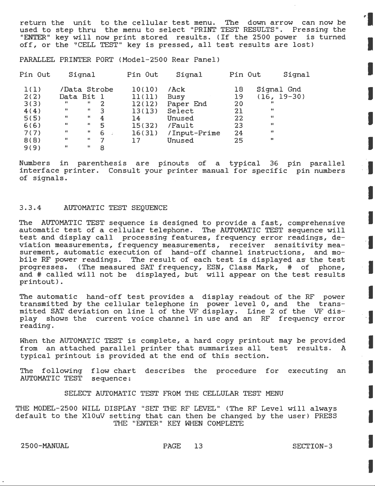
return
used
to
"ENTER"
off,
or
the
step
key
the
unit
thru
will
'1CELL
to
the
now
TEST"
the
menu
print
cellular
stored
key
to
is
test
select
results.
pressed,
menu.
The
down
arrow
"PRINT TEST RESULTS".
(If
the
all
test
2500
results
power
are
can
Pressing
is
lost)
now
be
the
turned
PARALLEL
Pin
Out
1(1)
2(2)
3(3)
4(4)
5(5)
6(6)
7(7)
8(8)
9(9)
Numbers
interface
of
signals.
3.3.4
The
AUTOMATIC
automatic
test
and
viation
surement,
bile
RF
progresses.
and
#
called
printout).
PRINTER
PORT
Signal
/Data
Data
Strobe
Bit
1 11<
2
3
4
5
6
7
8
in
parenthesis
printer.
AUTOMATIC
TEST
test
display
of
a
call
measurements,
automatic
power
readings.
(The
will
measured
not
<Model-2500
Pin
10(10)
12(12)
13(13)
14
15(32)
16(31)
17
are
Consult
TEST
SEQUENCE
sequence
cellular
processing
frequency
execution
The
be
displayed,
Out
11)
pinouts
your
is
designed
telephone.
measurements,
of
result
SAT
frequency,
Rear
Panel>
Signal
/Ack
Busy
Paper
End
Select
Unused
/Fault
/Input-Prime
Unused
of
printer
ma~ual
to
The
features,
hand-off
of
each
but
Pin
a
typical
provide
AUTOMATIC
frequency
receiver
channel
test
ESN,
will
Class
appear
Out
18
19
Signal
(16,
20
21
22
23
24
25
for
sp~cific
a
instructions,
is
displayed
Mark,
19-30)
II
II
II
II
II
II
36
fast,
TEST
error
sensitivity
on
the
Signal
Gnd
pin
pin
parallel
numbers
comprehensive
sequence
readings,
and
a~
the
#
of
phone,
test
results
will
de-
mea-
mo-
test
The
automatic
transmitted
mitted
play
SAT
shows
reading.
When
from
the
an
typical
The
following
AUTOMATIC
THE
MODEL-2500
default
to
2500-MANUAL
hand-off
by
the
deviation
the
AUTOMATIC
attached
printout
TEST
SELECT
WILL
the
XlOuV
test
cellular
on
line
current
TEST
is
parallel
is
provided
flow
chart
sequence:
AUTOMATIC
DISPLAY "SET
setting
THE
provides
telephone
1
voice
complete,
printer
at
describes
TEST
that
"ENTER"
of
the
channel
that
the
end
FROM
THE
RF
can
KEY
PAGE
a
display
in
VF
display.
in
a
hard
summarizes
of
the
THE
CELLULAR
LEVEL"
then
WHEN
13
readout
power
use
this
and
copy
level
printout
section.
procedure
(The
be
changed
COMPLETE
Line
an
all
TEST
RF
by
of
0,
and
2
RF
test
for
MENU
Level
the
the
RF
the
of
the
frequency
may
be
results.
executing
will
user)
SECTION-3
power
trans-
VF
dis-
error
provided
always
PRESS
A
an
Page 24

THE
MODEL-2500
WILL
DISPLAY
TRANSMITTING
FORWARD
CONTROL
CHANNEL
334
WHEN
A
NUMBER
WHEN
NOW
TEST
NOW
TEST
SUREMENT
~
iEN
A
THE
BRIEF
THE
"PLACE
ON
THE
THE
"CONNECT"
THE
HANDSET
THE
HOOK-FLASH
THE
MODEL-2500
THE
DISPLAY
NOW
DELAY
CELLULAR
CALL"
HANDSET
PROMPT
AND
PROMPT
DTMF
ENCODER
APPEARS
MODEL-2500
FUNCTION
THE
"bOWN
WILL
WILL
NOW
BE
VALUE :STORED
TERMINATE
~
TELEPHONE
THE
MODEL-2500
IS
WILL
DISPLAY
APPEARS
ON
PLACE A CALL
ON
THE
IS
ESTABLISHED
AND
PRESS
WHEN
ON
THE
ARROW"
MAKE
UPDATED
FOR
ARROW"
CALL
CHANNEL
LOCKED
KEY
THE
PRINT
AT
WILL
ON
CONTINUOUSLY,
OUT.
KEY.
THE
DISPLAY
334
THE
"PAGING
THE
MODEL-2500
FROM
MODEL-2500
THE
FINISHED
CELLULAR
WHEN
FINISHED
MAXIMUM
TO
CELLULAR
TRANSMITTING
CONTROL
MOBILE"
THE
CELLULAR
DISPLAY,
"DOWN
ARROW"
TELEPHONE
AUDIO
DEVIATION
WITH
PROCEED
TELEPHONE
CHANNEL,
DISPLAY,
TELEPHONE
KEY
AND
THE
PEAK
PRESS
THE
FORWARD
THE
ENTER
THE
CALL
ON
THE
PRESS
DEVIATION
"DOWN
CONTROL
MODEL-2500
THE
TIME
'
STORED.
THE
WHEN
.
WHEN
rHE
RF
LEVEL
THE
WILL
rER
STEP
THE
MODEL-2500
MODEL-2500
THE
SAT
FREQUENCY
SAT
FREQUENCY
MODEL-2500
THE
CELLULAR
MOBILE".
THE
MODEL-2500
"CONNECT"
WILL
UNTIL A READING
CALL
BE
TIME
WILL
PRINTED
BY
NOT
THRU
THE
NOW
WILL
WILL
WILL
NOW
NOW
TELEPHONE
TO
PROCEED
PROMPT
NOW
ARROW"
BE
TERMINATED.
OR
IF
NO
TURNING
MENU
FOR " PRINT
END
NOW
EXECUTE
EXECUTE
AND
DEVIATION
WILL
NOT
RESULTS
MEASURE
"RINGS",
ANSWER
APPEARS
EXECUTE
OF
12
dB
KEY
PRINTER
OFF
THE
OF
AUTOMATIC
AN
AUTOMATIC
BE
DISPLAYED
PRINTOUT
AND
THE
THE
ON
THE
RECEIVER
SINAD
TO
CONTINUE
IF
AUTOTEST
IS
CONNECTED,
UNIT
AND
TEST
AN
AUTOMATIC
<MUTED
AUDIO)
DISPLAY
MODEL-2500
CALL
THE
ON
DISPLAY,
IS
ONLY
RESULTS"
TEST
SEQUENCE
POWER
HAND-OFF
TEST.
WILL
BUT
WILL
ST
FREQUENCY
APPEAR
WILL
THE
CELLULAR
THE
CALL
SENSITIVITY
ACHIEVED.
PRINTOUT
RESULTS
USING
AND
IS
CAN
THE
PRESS
LEVEL
TEST.
DURING
BE
MEASURED
ON
AND
DEVIATION
DISPLAY
TELEPHONE
IS
ESTABLISHED
SINAD
PRESS
ENABLED,
BE
PRINTED
"DOWN
THE
ARROW"
"ENTER"
THIS
AND
THE
TEST
"ALERTING
TEST.
ADJUST
THE
RESULTS
KEY
KEY
.
"DOWN
AT
A
TO
2500-MANUAL
PAGE
14
SECTION-3
Page 25

I.
VIEWING
1.
The
2.
To
key,
3.
To
"DOWN"
4.
To
DATA
service
get
then
scroll
leave
STORED
into
hit
key.
the
monitor
the
either
through
viewing
must
viewing
the
mode,
the
data,
be
mode,
"UP"
the
in
the
the
the
or
user
user
CELLULAR
user
"DOWN"
must
must
must
key.
hit
hit
mode.
first
either
the
hit
the
the
"ENTER"
"SHIFT"
"UP"
key.
or
II.
III.
LOADING
1.
2.
3.
4.
5.
6.
SELECTING
1.
2.
3.
DATA
The
The
The
service.monitor
PRINTER
user
RESULTS"
If
the
RESULTS",
previous
A
"*P"
mine
pass/fail
TABLE
performed.
The
measurements
by
"PRINT
measurements
The
service
To
select
twice.
"SHIFT"
user
When
or
"FAIL"
VIEWING
measurement.
mobile
FOR
VIEWING
must
must
or
through
"CELL TEST"
then
mobile
or
"*F"
if
the
measurement
table
equals
PASS/FAIL
Then
key.
must
the
DATA,
will
EIA,CUST1,CUST2
TEST
will
monitor
a
PASS/FAIL
to
hit
PASS/FAIL
will
be
must
be
ENABLED
run
through
the
key
the
will
RESULTS".
Once
the
~ither
Then
data
test
be
selected.
will
remain
TABLE
toggle
the
"ENTER"
TABLE
be
printed
at
printed
must
be
main
is
to
results.
displayed
has
remain
in
be
TABLE,
through
desired
is
a
"*P"
the
(either
in
through
the
menu
hit
be
PASSED
This
before
in
If
the
memory.
in
the
key
equal
after
or
end
the
CELLULAR
the
AUTO
any
viewed
to
of
test
and
time
will
after
or
will
memory
the
the
PASS/FAIL
each
"*F"
PASS
only
a "PRINT TEST RESULTS"
power
CELLULAR
user
tables,
return
to
will
the
or
mode.
PROGRAM
and
do
a "PRINT TEST RESULTS".
before
default
the
measurements
FAILED
occur
until
is
turned
must
EIA,CUST1
measurement.
print-out
hit
the
TABLE
to
the
be
FAIL).
PARAMETERS
get
a
"PRINT
"PRINTING TEST
to
the
according
if
the
new
data
off,
mode.
the
user
is
displayed
main
or
CUST2, a "PASS"
displayed
the
is
the
"SHIFT"
must
menu.
Also
following
status
to
PASS/FAIL
routine.
TEST
to
deter-
the
is
loaded
key
hit
during
of
the
the
a
the
IV.
PRINTING
1.
The
2.
To
print
"SHIFT
that
PASS/FAIL
service
the
5 ENTER".
option
PARAMETERS & HEADING
monitor
custom
is
installed
must
pass/fail
This
be
will
14A
in
in
print
your
the
SERVICE
parameters
the
unit.
MONITOR
&
heading
parameters
mode.
you
&
heading
must
hit
if
Page 26

*******************************************
*
CT
*
MODEL-2500
*
*
AUTOMATIC
SYSTEMS I WAVETEK
CELLULAR
TEST
SERVICE
SEQUENCE
RESULTS
MONITOR
"'
*******************************************
*
*
*
*
DATE:
MOBILE
SERIAL
NUMBER
ID
NUMBER
DIALED
PASS/FAIL
STATION
POWI-:R
DIGITAL
DTHF
ST
ST
MAXIMUM
CLASS
CLASS=1
COLOR
TEST
FREQUENCY=
DEVIATION=
AUDIO
CUSTOMER:
(MIN)=
314-277-0683
(ESN)=
STD1STD2-
FROM
MOBILE=
PARAMETER
MARK=
TABLE
08
CONTINUOUS
CODE=
1
DEVIATION=
HEX-
2356880#
10000
8.
47
11.55
AC0679C2
172-01-162242
172-001124386
1234567
EIA
BANDWIDTH==
25MHZ
HZ
KHZ
KHZ
*PASS*
*PASS*
*PASS*
POWER
POWER
POWER
POWER
POWER
POWER
POWER
POWER
LEVEL=O
LEVEL=1
LEVEL=2
LEVEL=3
LEVEL=4
LEVEL=5
LEVEL=6
LEVEL=?
HAND-OFF
SAT
CHAN
FREQUENCY
TEST
2.92
2.92
2.04
724
321
DATA:
DEVIATION
13
5
1
SAT
WTS
WTS
WTS
Mr..lTS
MWTS
Mr..lTS
MWTS
MWTS
CHANNEL
FREQ
ERROR
----+---------+------------+------------+---------5970
0100
0200
0300
0400
0500
0600
6000
6031
5970
6000
6030
RECEIVER
UNIT
STATUS
HZ
HZ
HZ
HZ
HZ
HZ
1.
1.
1.
1.
1.
1.
80
80
82
88
84
86
SENSITIVITY
=
*FAIL*
KHZ
KHZ
KHZ
KHZ
KHZ
KHZ
+0.04
+0.03
+0.03
+0.03
+0.04
+0.03
-103
KHZ
KHZ
KHZ
KHZ
KHZ
KHZ
dBM
(>JOdB)
TX
POWER
2.75
2.62
2.33
2.17
2.15
2.3.1
WTS
r..lTS
WTS
WTS
WTS
WTS
*PASS*
*FAIL*
*FAIL*
*FAIL*
*FAIL*
*PASS*
*PASS*
*FAIL*
*PASS*
*PASS*
*PASS*
*PASS*
*PASS*
*PASS*
*FAIL*
15
Page 27

PASS/FAIL
TABLE
PARAMETERS
TEST
LIMITS
PARAMETER
---------------------+---------------+---------------+--------------------PASS/FAIL
---------------------+------------~--+---------------+----
SAT
FREQUENCY
---------------------+---------------+--------~------+---------------------
SIGNALING
FREQUENCY
TABLE
TONE
EIA
SAT
+/-
10KHz
+/-
1Hz
1Hz
CUSTOM
(SEE
NOTE
1
1)
CUSTOM
(SEE
-
2
NOTE
----------------
1)
MAX=
+/-5Hz
MAX=
+/-5Hz
---------------------+---------------+---------------+---------------SIGNALING
DEVIATION
---------------------+------------~--+---------------+----------------
MAX.
DEVIATION
---------------------+---------------+---------------+---------------------PWR
LVL
TONE
O(SEE
NOTE
2)
MAX
MIN
<=
MAX
4.00
= 8.8KHz
= 7.2KHz
12KHz
MIN
-
1.12
MAX=9.99KH
MIN=6.00KH~
MAX=14.
99K
MAX/MIN
I 4.00/0
i
·
---------------------+---------------+---------------+---------------------PWR
LVL
1
1.78-
.447
I 4.00/0
---------------------+---------------+---------------+----------------------PWR
LVL
---------------------+---------------+---------------+---------------------PWR
LVL
2 . 708 - . 178 I I . 999/0
3 . 282 - .
071.
I I . 999/0
·
---------------------+---------------+---------------+---------------------PWR
LVL
4
.112
-
.028
I .999/Q
---------------------+---------------+---------------+----------------------PWR
LVL
5 . 045 - . 011 I . 999/0
---------------------+---------------+---------------+---------
PWR
LVL
6
.018
-
.005
I I .999/0
~
------------
---------------------+---------------+---------------+----------------------PWR
LVL
7 . 007 - . 002 I . 999/0
---------------------+---------------+---------------+----------------------
SAT
DEVIATION
MAX
= 2.2KHz .
MIN = 1.
8KHz
---------------------+---------------+---------------+---------------------TRANSMIT
ERROR
FREQ.
+/-
(SEE
2.0,6KHz
NOTE
3)
---------------------+---------------+---------------+---------------------12dB
SINAD
<=
-116
dBm
MAX=3.00KHz
MIN=l.
MAX
ERROR=
+/-
3.00KHz
MAX=-100dBi
·
OOKH
'
·
·
..
---------------------+---------------+---------------+----------------------NOTE
NOTE
NOTE
1:
SHOWN
2:
THE
MAXIMUM
3:
CUSTOMER
ARE
THE
THE
MAINTAINED
CHANGING
-
WHEN
IN
THIS
TABLE
THE
IN
SELECT
WILL
THAT
SPECIFIED LIMITS
THE
MINIMUM/MAXIMUM
MAXIMUM
POWER
EIA
SPECIFIES
WITHIN+/-
PASS/FAIL
THE
CELLULAR
PASS/FAIL
TOGGLE
IS
DESIRED
POWER
LEVEL
MEASURED
THAT
2.5
PPM.(EXAMPLE-CHANNEL
TABLE
MODE,
MODE.
THROUGH
THE
AND
VALUES
BY
THE
THE
HIT
TO
TABLES.
HIT
ARE
AVAILABLE
ALLOWED.
SPECIFIED
MODEL
MOBILE
THE
CHANGE
"SHIFT"
TABLES
TO
THE
"ENTER"
15A
BY
EIA
2500
IS
STATION
KEY
KEEP
LEAVE
KEY.
AS
AN
OPTION.
IN
PWR
LVL 0 IS
4.00
WATTS.
CARRIER
FREQUENCY
991,824.040
TWICE.
THIS
HITTING
THE
PASS/FAIL
THE
VALUES
4.47
WATTS.
MUST
MHz,=+/-2.06KHz)
WILL
THE
MODE,
PUT
"SHIFT"
FIND
YOU
KEY.
BE
THE
Page 28

3.3.5
The
MOBILE
telephone
procedure
MOBILE
TO
CELL
to
the
for
placing
TO
cell
CELL
CALL
a
CALL
test
site.
MOBILE
TEST
is
used
The
TO
to
following
CELL
originate
CALL:
a
flow
call
chart
from a cellular
describes
the
3.3.6
The
CELL
the
cell
placing
SELECT
MOBILE
TEST
THE
MODEL-2500
(The
RF
THE
MODEL-2500
WHEN
THE
level
2500 DISPLAY,
A
WHEN
THE
NOW
CELL
TO
TO
MOBILE
MOBILE
site.
a
CELL
TO
MOBILE
TO
CELL
MENU
AND
WILL
will
THE
always
"ENTER"
WILL
CONTROL
"PLACE
CALL"
ENTER A NUMBER
CALL
"CONNECT"
DISPLAY,
FROM
THE
PROCEED
PROMPT
TO
<SECTION
CALL
CALL
The
test
following
CALL:
CALL
PRESS
DISPLAY
default
KEY
DISPLAY
CHANNEL
PROMPT
THE
CELLULAR
APPEARS
CALL
MANUAL
TEST
is
used
flow
TEST
WHEN
FROM
THE
"SET
COMPLETE
THE
"ENTER"
THE
RF
to
the
TRANSMITTING
334
APPEARS
ON
THE
ON
HANDSET
TELEPHONE
ON
THE
IS
ESTABLISHED
TEST
OPERATIONS
3.4.7}
to
page a cellular
chart
describes
CELLULAR
KEY
LEVEL"
XlOuV>
PRESS
FORWARD
THE
MODEL-
AND
PLACE
MODEL-2500
the
telephone
procedure
from
for
SELECT
THE
(The
setting
THE
MODEL-2500
ENTER
THE
CELL
TEST
TO
MENU
MODEL-2500
RF
level
that
PRESS
THE
WILL
MOBILE
THE
IF
PRESS
MOBILE
THE
ID
NUMBER
THE
MODEL-2500
MOBILE
AND
WILL
will
can
always
then
"ENTER"
PROMPT
NUMBER
ID
NUMBER
DISPLAYED
ENTER
WILL
DISPLAY
CONTROL
CALL
PRESS
TEST
THE
DISPLAY
default
be
changed
KEY
FOR
THAT
OF
KEY
TO
CHANNEL
FROM
"ENTER"
"SET
WHEN
THE
IS
TO
THE
IS
BEGIN
THE
CELLULAR
KEY
THE
RF
to
the
by
the
COMPLETE
CELLULAR
BE
PAGED
CELLULAR
NOT
CORRECT
THE
TEST
TRANSMITTING
334
LEVEL"
XlOuV
user>
TELEPHONE
TELEPHONE
FORWARD
2500-MANUAL
PAGE
16
SECTION-3
Page 29
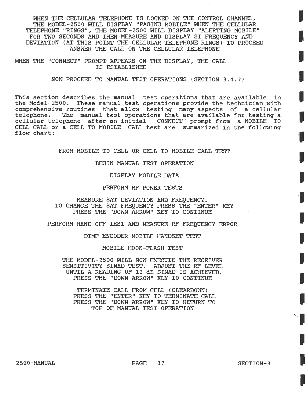
WHEN
THE
THE
MODEL-2500
TELEPHONE
FOR
TWO
SECONDS
DEVIATION
CELLULAR
WILL
"RINGS",
AND
CAT
THIS
ANSWER
TELEPHONE
DISPLAY
THE
MODEL-2500
THEN
POINT
THE
MEASURE
THE
CALL
IS
LOCKED
"PAGING
WILL
AND
CELLULAR
ON
THE
CELLULAR
ON
THE
CONTROL
MOBILE"
DISPLAY
DISPLAY
WHEN
"ALERTING
ST
TELEPHONE
TELEPHONE
CHANNEL,
THE
CELLULAR
FREQUENCY
RINGS)
TO
MOBILE"
AND
PROCEED
WHEN
THE
"CONNECT"
NOW
This
the
section
Model-2500.
comprehensive
telephone.
cellular
CELL
flow
telephone
CALL
chart:
or a CELL
TO
PROCEED
describes
These
routines
The
FROM
MOBILE
MEASURE
CHANGE
PRESS
PROMPT
IS
TO
the
manual
manual
after
TO
MOBILE
BEGIN
THE
THE
APPEARS
ESTABLISHED
MANUAL
TEST
manual
test
that
test
an
allow
operations
initial
CALL
TO
CELL
OR
MANUAL
DISPLAY
PERFORM
SAT
SAT
"DOWN
RF
DEVIATION
FREQUENCY
ARROW"
ON
THE DISPLAY, THE
OPERATIONS
test
operations
operations
testing
that
provide
many
are
"CONNECT"
test
CELL
TEST
MOBILE
POWER
are
TO
summarized
MOBILE
OPERATION
DATA
TESTS
AND
FREQUENCY.
PRESS
KEY
THE
TO
CONTINUE
CALL
(SECTION
that
the
aspects
available
prompt
CALL
"ENTER"
TEST
3.4.7)
are
technician
of
from
in
KEY
available
a
cellular
for
testing
a
MOBILE
the
following
in
with
a
TO
PERFORM
2500-MANUAL
HAND-OFF
DTMF
TEST
ENCODER
MOBILE
THE
MODEL-2500
SENSITIVITY
SINAD
UNTIL A READING
PRESS
THE
"DOWN
TERMINATE
PRESS
PRESS
THE "ENTER"
THE
TOP
"DOWN
OF
AND
MOBILE
HOOK-FLASH
WILL
NOW
TEST.
OF
12
ARROW"
CALL
FROM
ARROW"
MANUAL
PAGE
MEASURE
RF
FREQUENCY
HANDSET
TEST
TEST
EXECUTE
ADJUST
dB
SINAD
KEY
THE
THE
IS
TO
CONTINUE
CELL ( CLEARDOWN)
KEY
TO
TERMINATE
KEY
TO
RETURN
TEST
OPERATION
17
ERROR
RECEIVER
RF
LEVEL
ACHIEVED.
CALL
TO
SECTION-3
Page 30

Each
Continue
displayed.
line
display.
from
Therefore,
"DOWN
of
manual
of
top
ARROW"
these
test
to
press
The
the
The
to
bottom,
when
will
manual
operation
the
test
VF
display,
manual
and
"TERMINATE
return
test
operations
is
"DOWN
currently
followed
test
then
the
selected
ARROW"
being
operations
back
CALL
FROM
program
is
described
key
executed
by
the
routine
to
the
CELL"
back
by
until
pressing
the
is
test
top,
to
data
is
test
"DISPLAY MOBILE DATA".
in
the
desired
displayed
designed
as
many
is
reached,
the
following
on
"DOWN
manual
line
to
times
ARROW"
test
on
the
first
2
of
the
be
repeated
as
desired.
pressing
paragraphs.
key.
is
VF
the
Each
Display
This
ment
To
data
ARROW"
chart.
RF
This
(0-7),
cellular
phone,
will
cellular
new
When
proceed
Measure
This
the
with
is
handset
on
selection
view
Power
RF
all
selection
current
the
the
the
Mobile
serial
the
mobile
readout.
key
selection
and
press
transmit
power
SAT
Model-2500
to
Tests
the
telephone.
the
telephone.
reading.
power
to
the
SAT
Frequency
SAT
cellular
deviation.
on
the
Data
provides
number
When
proceed
displays
RF
"ENTER"
a
forward
levels
next
performs
frequency
telephone
cellular
VF
<ESN),
data,
all
power
To
The
have
selection
and
Voice
display.
display
mobile
press
mobile
to
the
the
transmitted,
change
key
new
two
telephone,
current
to
voice
power
been
in
Deviation
different
transmitted
transmitter
deviation
readout
dialed
the
"ENTER"
data
next
the
advance
channel
tested,
the
of
has
selection
cellular
in
RF
power
to
level
manual
functions.
may
and
monitoring
mobile
number,
key
to
been
telephone
Watts,
output
the
next
power
will
by
deviation.
press
test
the
be
change
be
tested
ID
and
move
viewed,
in
the
or
milli-watts,
on
RF
displayed
the
flow
The
cellular
The
the
number
station
to
the
press
manual
RF
the
cellular
power
instruction
along
"DOWN
chart.
Model-2500
by
ARROW"
telephone
deviation
speaking
deviation
(MIN),
class
next
the
test
power
level.
equip-
mark.
mobile
"DOWN
flow
level
from
displays
into
the
tele-
This
to
the
with
key
along
reading
reading
a
to
the
The
quency,
SAT
When
ARROW"
chart.
2500-MANUAL
second
press
frequency
all
key
function
the
and
deviation
to
proceed
allows
"ENTER"
deviation
and
SAT
to
the
key
reading
tests
the
technician
to
move
have
next
PAGE
to
will
been
selection
18
to
the
be
dislayed.
change
next
completed,
available
in
the
the
manual
current
SAT.
press
SECTION-3
SAT
the
test
The
"DOWN
fre-
new
flow
Page 31

Hand-off
and
Measure
RF
Frequency
Error
This
frequency
use,
measurement
phone's
allows
transmitter.
This
valid
hand-off
channel
ed,
by
When
the
flow
DTMF
This
cellular
verify
play.
proceed
manual
along
test
voice
a
hand-off
the
Model-2500,
all
"DOWN
chart.
Encoder
test
that
When
frequency
for
is
to
test
error.
with
is
displayed
monitoring
also
channel,
frequency
ARROW"
is
telephone.
allows
channel
entered,
instruction
Test
designed
the
all
the
next
is
The
an
error
and
and
key
keys
DTMF
used
Model-2500
RF
frequency
in
with
the
for
by
entering
then
it
will
the
error
to
proceed
to
Press
pressed
keys
selection
for
testing
kilohertz,
respect
frequency
manual
pressing
be
displayed.
will
new
voice
and
hand-off
test
the
are
have
been
in
displays
error
control
a
four
the
be
transmitted
to
DTMF
the
now
the
the
DTMF
tested,
cellular
the
measurement.
and
indicates
to
the
accuracy
of
digit
"ENTER"
When
channel
tests
next
encoder
keys
displayed
manual
on
telephone
current
current
of
voice
number
key.
the
to
will
have
selection
the
on
press
test
channel
the
channel
that
"ENTER"
the
be
displayed.
been
on
the
cellular
the
the
flow
hand-off,
voice
The
As
chart.
frequency
the
cellular
cellular
in
Model-2500
"DOWN
cellular
in
hand-off
corresponds
the
key
completed,
the
handset
telephone,
ARROW"
channel
use.
telephone
new
is
telephone
manual
and
error
tele-
This
to
any
to
hand-off
press-
press
test
of
the
and
VF
dis-
key
RF
in
a
to
Mobile
This
function
burst
by
phone.
will
ARROW"
chart.
Receiver
During
with
control
LEVEL"
Model-2500.
receiver
front
indicated
Hook-flash
test
of
pressing
be
displayed.
key
this
a
of
button,
panel
is
designed
in
a
cellular
signalling
the
hook-flash
If
the
hook-flash
to
proceed
Sensitivity
test
1000
sensitivity.
by
the
Manual
will
the
Hz
RF
Test
tone
When
Test
the
transmit
tone
generator
and
adjusting
control
change
RF
Level
to
verify
telephone.
from
switch
the
to
plus
Pressing
the
LEOs
the
is
hook-flash
the
SAT
output
of
range
cellular
on
detected
next
carrier
at
the
the
next
proper
The
the
selection
a
deviation
level
front
RF
the
"RF LEVEL"
of
the
to
operation
hook-flash
telephone.
handset
by
the
test
from
generator
the
is
panel
RF
generator
front
is
of
the
Model-2500,
complete,
in· the
the
Model-2500
level
possible
RF LEVEL
can
button
panel
of
the
consists
Execute
cellular
manual
of
14
by
be
used
on
output
vernier.
"HOOK-FLASH"
of
this
tele-
an
indication
press
vernier
the
the
test
is
modulated
kHz.
using
for
Model-2500
level
Please
a
400ms
test
"DOWN
flow
Manual
the
on
testing
as
"RF
the
2500-MANUAL
PAGE
19
SECTION-3
Page 32

note
of
value
This
The
that
-116
will
three
dBm
may
cellular
may
pe
measured
Model-2500
made
the
since
(.35
cause
show
RF
up
LEVELS
telephone
front
Sinad
reading
the
uv>,
the
cellular
as
available
under
by
connecting
panel
sensitivity
adjusting
of
the
telephone
a
RF
cellular
generator
to
lose
a "MOBILE DISCONNECTED"
are
the
"X-lOuv,
test
"SINAD
will
has
the
AUDIO
not
the
cellular
be
accurate.
received
IN"
telephone
connector.
telephone
output
the
failure
X-luv,
audio
signal
on
and
available,
audio
If
is
level
and
the
X-.luv.
signal
no
on
the
below
disconnect.
Model-2500.
If
the
to
connection
order
this
the
Sinad
the
is
When
key
the
to
Terminate
This
operation
manual
release
gress
nate
from
the
selection
3.3.8
During
to
indicate
displayed,
main
CELLULAR
table:
Message
FAILED
receiver
proceed
Call
operation
order
the
call
in
ERROR
a
cellular
press
INITIAL
to
from
will
tests
to
the
cell
in
the
manual
MESSAGES
a
failure
TEST
VC
sensitivity
the
next
Cell
terminate
are
cellular
site.
progress,
test
telephone
in
the
"ENTER"
MENU.
test
selection
(Cleardown)
the
complete,
telephone,
Pressing
but
flow
test,
the
test
key
Error
Meaning
Mobile
channel
is
in
current
press
the
will
chart.
certain
procedure.
to
resume
messages
failed
designation.
complete,
the
manual
call
the
and
"DOWN
ARROW"
return
error
operation
are
the
press
test
in
progress.
"ENTER"
terminate
key
to
the
messages
After
an
listed
intial
the
flow
"DOWN
chart.
ARROW"
When
key
to
transmit
the
call
will
not
in
termi-
DISPLAY MOBILE
may
be
displayed
error
and
in
return
the
message
to
following
voice
all
a
proDATA
is
the
INCORRECT
LOST
SAT
MOBILE
NO
MOBILE
NO
MOBILE
DCC
DISCONNECTED
2500-MANUAL
CARRIER
RESPONSE
Digital
the
mobile
SAT
color
was
frequency
appeared.
Mobile
sequence
sequence
error
Mobile
the
has
in
carrier
current
signalled
depending
in
the
Mobile .station
control
channel
Model-2500.
PAGE
20
code
incor-rect.
from
use,
test.
was
channel
did
instructions
returned
mobile
on
this
not
in
not
has
a
disconnect
the
may
not
detected
use.
respond
from
dis-
test
be
from
SECTION-3
an
on
to
Page 33

3.4
SERVICE
MONITOR
MODE
APPLICATION
NOTES
This
commonly
followed
controls.
receiver
section
outlines
required
by
a
The
measurements
applications.
description
application
how
or
transmitter
to
of
notes
use
the
the
CT
A
brief
steps
are
grouped
measurements
Systems
overview
to
take
Model
of
and
together
as
each
their
shown
2500
as
in
test
related
either
below:
some
is
2500-MANUAL
PAGE
21
SECTION-3
Page 34

SECTION
1
RECEIVER
3.4.1
3.4.2
3.4.3
3.4.4
3.4.5
3.4.6
SECTION
MEASUREMENTS
RECEIVER
SENSITIVITY - 12
MODULATION
RECEIVER
RECEIVER
BANDWIDTH
CTCSS
2
DECODER
AUDIO
DISTORTION
DB
ACCEPTANCE
IF
BANDWIDTH
SENSITIVITY
TEST
SENSITIVITY
MEASUREMENT
SINAD
BANDWIDTH
AND
WITH
SYMMETRY
CTCSS
TEST
DECODER
AND
DECODER
TRANSMITTER
3.4.7
3.4.8
3.4.9
3.4.10
3.4.11
MEASUREMENTS
OFF
THE
AIR
RELATIVE
MEASURING
TUNING
SIGNAL
TRANSMITTER
SUB-AUDIBLE
MISCELLANEOUS
MONITORING
STRENGTH
POWER
TRANSMITTER
KEYBOARD
MEASUREMENTS
AND
FREQUENCY
TONES
PROGRAMMING
ERROR
2500-MANUAL
PAGE
22 SECTION-3
Page 35

SECTION 1
APPLICATION NOlES
RECEIVER
3.4.1
An
distortion
the
not
and
NOTE:
quality
Refer
1>
2)
3)
4)
Receiver
important
audio
be
valid
noise
to
Cable
IN/OUT"
Cable
"AUDIO/IN".
Select
Select
deviation,
MEASUREMENTS
Audio
factor
of
circuits
in
For
audio
Figure
the
Audio
1 kHz
the
since
determining
%
distortion
distortion
antenna
port
GEN
processed
causing
3-3
of
output
mode.
and
i.e.,
Distortion
in
proper
SINAD
for
the
3000kHz
combines
sensitivity.
lower
analyzer
the
port
Model
or
adjust
Measurement
recovered
high
distortion,
than
following
of
the
2500.
speaker
1 kHz
if
receiver
the
1%,
with
test
receiver
terminals
max
allowable
alignment
audio.
the
distortion
it
greater
procedure.
level
If
problems
12
dB SINAD
factor
is
best
resolution.
under
of
receiver
control
is
5kHz.
is
to
test
for
knowing
exist
test
with
use
to
to
60%
will
signal
a
the
SINAD
of
the
in
lab
"RF
max
5)
6)
7)
8)
Select
Adjust
Adjust
Volt-meter
where
Press
readout
NOTE:
time
RF
Audio
V =
the
it
VOLTS
level
receiver
Feature,
Power
speaker
SINAD
of
distortion
SINAD
is
pressed.
mode.
control(s)
volume
and
=
-----------
voltage
once
button
2r
or
in
toggles
to
to
the
v
spk
and
twice
%.
fully
full
formula:
r
spk
(as
between
quiet
rated
=
speaker
required)
dB
receiver
audio
impedance
to
and
%
( 1
mV>.
power,
obtain
expressions
a
using
direct
each
2500-MANUAL
PAGE
23
SECTION-3
Page 36

CT
5YSTE1o4S,INC.
M
WATTS
0
CEU..I..\.AR
0
SERVICE
2
I
3 - I
~~p
I
STORE I --
4
I 5
I 6
I
7
I
8
I
I 9
I
t
+
SHIFT
AUOIO
SINAO
RE
CALL
sue
TON(
C[LL
TEST
IN
I
lt:C
SQUELCH
TEST
MONITOR
SQUELCH
@
@
(
SPK
OUT
FIGURE
3-3.
RECEIVER
AUDIO
!;"
2500-MANUAL
RECEIVER
PAGE
UNDER
TEST
DISTORTION
-
---------
24
-
=-·
ANT
~
MEASUREMENT
SECTION-3
Page 37

3.4.2
Sensitivity
-
12
dB SINAD
Sensitivity
if
they
SINAD
into
of
is
The
SINAD
account.
RF
required
"challenged"
RF
is
Signal
and
The
is
expressed
Model
results
receivers
Causes
of
analyzed
output.
ar~
is
a
level
defined
Noise
to
for
distortion
by
measurements
to
be
truly
unit
2500
the
An
accepted
to
measure
with
for
as
+
Noise
+
Distortion
in
quickly
nearest
of
this
the
dB.
measure
60%
optimum
connecting
should
meaningful.
that
definition
12
dB SINAD
of
the
measurement
voltage
+
Distortion
performs
dB.
~~Lis
performance.
such
as
an
oscilloscope
reflect
is
systems
ratio:
SINAD
allows
high
signal
designed
of
sensitivity
from
a
maximum
is
typically
measurements
the
noise
or
to
+
noise
to
take
receiver
deviation.
expressed
user
audio
the
Model
and
these
is
"the
whose
and
displays
to
rapidly
clipping
2500's
distortion
factors
amount
bandpass
in
tune
may
Demod
uV.
the
be
Refer
1)
2)
3)
4)
5)
6)
to
Figure
Connect
the
"RF IN/OUT"
Connect
speaker
and
it
impedance
Select
the
Program
numerical
Select
the
For
the
receivers
example,
specified
Select
the
3-4
for
the
RF
input
the
of
"SINAD
the
disconnects
must
be
GEN
the
receiver
keys
followed
1 kHz
maximum
if
as
5 kHz
AC
pk
the
(antenna-port)
jack
on
AUDIO
receiver.
the
substituted.
mode.
frequency
modulation
the
then
5 kHz X
volts
following
the
Model
IN"
If
internal
by
the
deviat:i.on
maximum
the
test
.6
mode
on
test
2500.
jack
the
speaker,
in
~1z
ENTER
function
using
deviation
deviation
=
3000
the
procedure.
of
the
of
the
external
on
key.
Hz
Model
the
and
the
2500.
receiver
Model
speaker
a
load
Model
adjust
1kHz
of
would
2500
having
level
the
be:
under
acros
jack
2500
it
receiver
test
is
the
using
for
control.
,s
60%
to
the
used
same
the
of
is
7)
8)
Open
Adjust
the
specified
to
determine
2500-MANUAL
squelch
the
by
receiver
the
audio
control
volume
radio
power
on
the
receiver.
to
achieve
manufacturer.
using
the
PAGE
full
Use
formula:
25
rated
the
audio
internal
power,
voltmeter
SECTION-3
as
Page 38

2r
v
spk
v
-----r
spk
for
a
sinewave
=
Audio
Power
9)
10)
11)
where
Select
Adjust
SINAD
The
setting
V =
speaker
the
SINAD
the
reading
sensitivity
on
the
RF
of
voltage
function
level
12
of
Model
dB.
the
range
receiver
2500
and
on
RF
r
the
and
level
spk
Model
vernier
may
dial.
=
speaker
now
2500
on
be
impedance.
for
a
the
Model
expressed
reading
2500
as
in
the
dB.
for
a
uV
2500-MANUAL
PAGE
26
SECTION-3
Page 39

0 CEU.ll..AA TEST
0
SliMCE
MONITOR
t51<HZ 0
POw£'!..
~AU~
~off
SYNTH£J
VEL
@ ®
OOT
•
MOO
@
2 3
5 6
8
0
IN
9
ENTER
DE
MOO
SPK
OUT
RF
STEP
t
•
SHIFT
SINAO
AUDIO
AE
-CAU:
SUB
TONE
CELL
TEST
IN
SQUELCH
@
ANT
IN
-2
50
0
-MANUAL
FIGURE
3-4.
SENSITIVITY - 12
PAGE
27
DB
SINAD
SECTION-3
Page 40

3.4.3
In
Modulation
FM
voice
certain
Acceptance
modulated
reduction
Bandwidth.
Acceptance
receivers
in
Bandwidth
SINAD
the
maximum
sensitivity
deviation
is
called
accepted
Modulation
for
a
Since
poor
sensitivity
optimize
essential
modulation
in
degraded
Refer
1)
2)
to
Perform
Increase
sensitivity
the
3)
Increase
4)
Activate
5)
Multiply
Modulation
[New
Bandwidth
Modulation
with
receiver
in
acceptance
Receiver
Figure
the
2500
RF
the
the
deviation
Modulation,
performance.
maintaining
sensitivity.
3-5
for
12
dB SINAD
the
Model
point
output
1 kHz
DEV
the
increase
Acceptance
-
Previous
acceptance
a
bandwidth
the
following
test
2500
(a
6 dB
dial).
level
mode
on
Bandwidth
bandwidth
this
This
test
operating
communications
is
poor,
test
described
RF
level
increase
setting
the
in
deviation
is
until
Model
as
shown
deviation]
becomes
system
and
exceeded,
procedure.
in
the
6 dB
two
times
12
dB SINAD
2500.
by
below:
X 2 =
results
important
characteristic
since
it
previous
over
the
the
uV
is
two
to
Modulation
in
degraded
to
is
when
will
section.
12
dB SINAD
setting
read
again.
obtain
Acceptance
fully
also
the
result
on
the
2500-MANUAL
PAGE
28
SEC'I'ION-3
Page 41
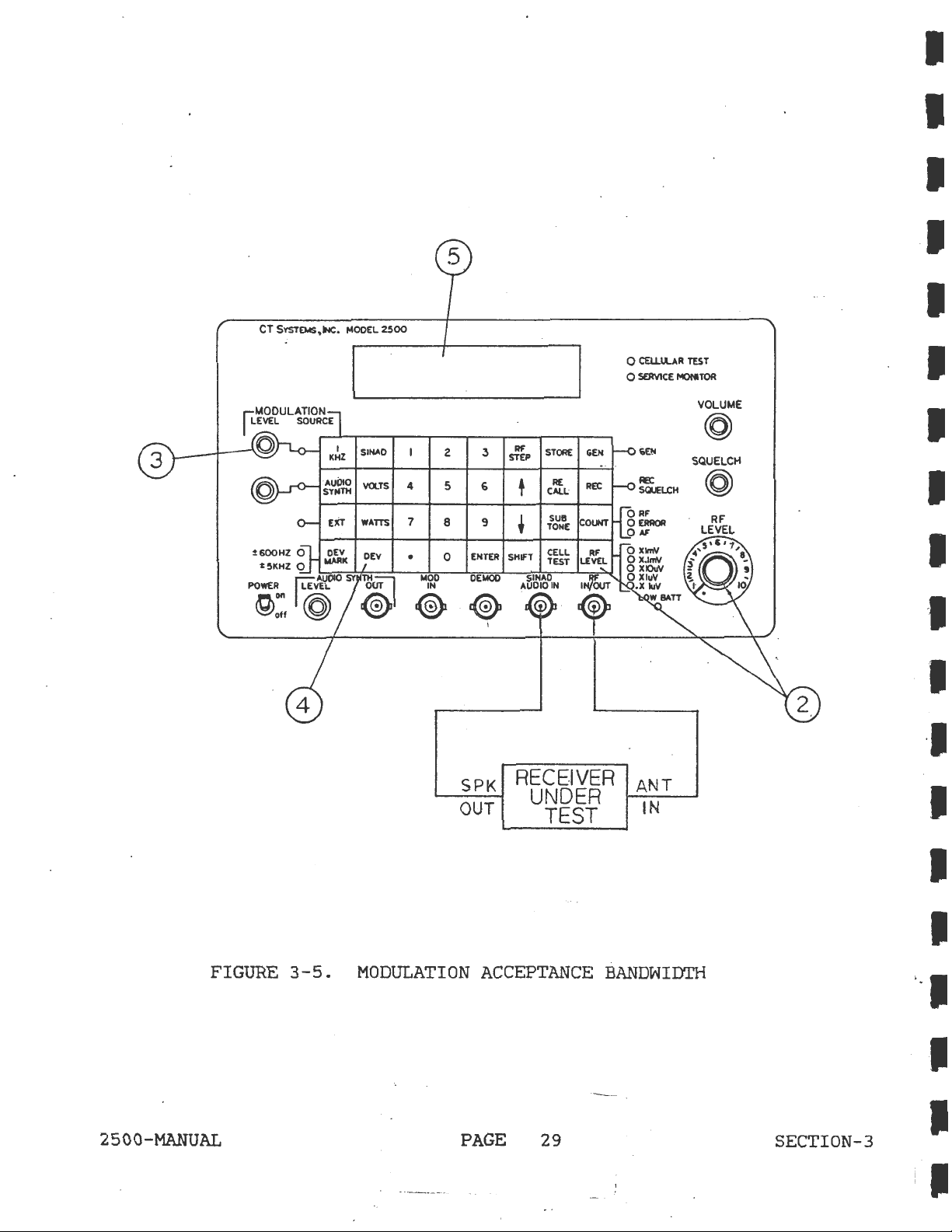
4 5
7
•
MOO
IN
@
2
8
0
3
6
9
ENTER
DE
MOO
c@)
Ill'
STEP
+
•
SHifT
AUOIO
SINAO
G)
STORE
RE
CALL
SUB
TONE
CELL
TEST
IN
GEH
REt
RF
LEVEL
0
CELL~R
0
SERVICE
TEST
MONITOR
VOLUME
@
SQUELCH
@
FIGURE
2500-MANUAL
3-5.
SPK
OUT
MODULATION
ACCEPTANCE
PAGE
RECEIVER
UNDER
TEST
BANDWIDTH
29
ANT
IN
SECTION-3
; .
I
Page 42

3.4.4
Receiver
IF
Bandwidth
and
Symmetry
This
test
<whether
too
narrow
will
cause
cause
filter
cutoff
form
of
Refer
1)
Connect
(antenna
2)
Select
3)
Program
followed
4)
Connect
5)
Set
6)
Select
kHz
or
of
high
is
correct,
too
positive
to
Figure
RF
deviation.
will
not
determine
the
bandwidth
noise,
this
noise
low)
the
peak
3-6
the
"RF IN/OUT"
jack)
GEN
the
by
mode.
receiver
the
receiver
LEVEL
DEV
and
, 1 kHz
high
will
and
but
result
for
of
ENTER
audio
the
and
cause
test
distortion.
is
offset,
will
clipping.
the
the
receiver
frequency
to
vernier
source,
IF
filter
low
cutoff
distortion,
is
a
good
(i.e.,
be
following
jack
of
key.
"SINAD
controls
and
points
troubleshooting
If
distorted
test
the
under
in
test.
MHz
AUDIO
to
adjust
bandwidth
are
and
a
the
Bandwidth
high
cutoff
recovered
procedure.
Model
2500
using
IN".
1
mV.
1 kHz
and
correct).
too
too
to
the
level
the
symmetry
wide
aid
bandwidth
in
of
low
audio
the
RF
numerical
control
Since
finding
the
or
low
in
the
input
keys
for
a
IF
5
7)
8)
9}
10)
11)
12)
13)
Select
Adjust
Connect
point
of
Reduce
Increase
Select
step
size
Select
until
as
Use
then
noted
the
the
the
continue
in
difference
the
3 dB
off
from
the
AC
receiver
high
Receiver.
RF
output
RF
output
RF
step
using
GEN
and
AGC
"high"
down
Step
between
bandwidth.
the
pk
VOLTS
squelch
resolution
by
back
and
program
the
use
voltage
frequency.
arrow
decreasing
10
is
center
function.
to
VOM
3 dB
to
numerical
the
UP
noted
key
to
obtained.
the
the
The
high
symmetry
same
full
Cin
(30%).
1
mV.
the
Model
keys
arrow
~n
return
the
RF
frequency
amount
open
DC
mode)
Make
followed
key
Step
to
frequency
Record
is
as
position.
to
note
2500
to
10
increase
is
the
for
RF
the
and
good
if
the
AGC
of
a
100
by
the
the
obtained.
center
until
"low"
the
high
low
the
low
frequency.
or
limiter
AGC
Hz
(.
ENTER
RF
frequency
Record
frequency
the
AGC
frequency.
frequency
frequency
test
voltage.
OOOlMHz)
key.
this
and
voltage
The
is
is
2500-MANUAL
PAGE
30
SECTION-3
Page 43

CT
SYSTD4S.INC.
MOOEL
~00
2500-MANUAL
FIGURE
3-6.
SPK
OUT
RECEIVER
PAGE
RECEIVER
UNDER
TEST
AGC
BANDWIDTH
31
AND
ANT
IN
SYMMETRY
SECTION-3
Page 44

3.4.5
Receiver
Test
Sensitivity
with
CTCSS
Decoder
and
Decoder
Bandwidth
This
test
unsquelch
of
the
from
much
test
desired
decoder
transmitters
receiver.
This
Refer
l)
2)
3)
4)
5)
second
to
Connect
the
"RF IN/OUT"
Select
Select
Set
the
the
numerical
Put
the
squelch
determines
a
receiver
determines
CTCSS
bandwidth
test
Figure
the
GEN
AUDIO
Audio
receiver
for
with
is
3-7
RF
mode
SYNTH
Synthesizer
keys
threshold.
the
that
the
frequency
can
tone
frequencies
sometimes
for
the
input
jack
and
(antenna
on
set
.
followed
under
amount
uses
a CTCSS
amount
and
be
a
problem
called
following
the
Model
the
RF
to
by
test
of
still
port)
Output
the
the
into
RF
the
near
Tone
test
2500.
subtone
Decode
signal
decoder.
encoder
unsquelch
if
wide
the
Squelch
procedure.
of
the
level
ENTER
that
The
oscillator
the
enough
desired
Sensitivity.
receiver
to
0.1
frequency
key.
Mode
and
is
required
Bandwidth
can
receiver.
to
allow
to
operate
under
uV.
in
Hz
adjust
drift
other
test
using
to
part
Too
the
to
its
6)
7)
8)
9)
10)
ll)
Adjust
Turn
Activate
Toggle
Vary
which
the
or
to
manufacturer's
off
AUDIO
Increase
comes
ceiver
unsquelched
sensitivity
the
frequencies
by
the
ENTER
the
the
decoder
Audio
audio
l kHz
SYNTH
RF
AUDIO
in
receiver
bandwidth.
Synthesizer
synthesizer
and
back
LEVEL
(l
from
SYNTH
l
Hz
key.
unsquelched
level
recommended
by
toggling
adjust
level
on.
vernier
kHz
the
control
tone
RF
frequency
increments
The
difference
control
deviation.
to
is
heard+
level
using
at
the
the
3 kHz
until
dial.
to
either
the
between
last
to
600
AUDIO
SYNTH
deviation.
the-receiver
noise).
side
numerical
the
frequencies
RF
level
Hz
Read
keys
deviation,
key.
just
the
of
selected
followed
setting
beRe-
at
is
2500-MANUAL
PAGE
32
SECTION-3
Page 45

CT
SYSTEMS,
INC.
MOOEL
2500
5
2 .3
5 6
7
8 9
0
•
MOO
IN
@
RECEIVER
Ill'
STEP
•
•
SHIFT
ENTER
MOO
SINAO
AUDIO
@
DE
®
UNDER
TEST
STORE
AE
CAU;
SUII
TONE
CELL
TEST
IN
ANT
IN
0 CEU.U..AA
0 SEJMCE
TEST
MONITOR
VOLUME
@
2500-MANUAL
FIGURE
WITH.CTCSS
3-7.
DECODER
RECEIVER
AND
DECODER
PAGE
SENSITIVITY
BANDWIDTH
33
TEST
SECTION-3
Page 46

3.4.6
CTCSS
Decoder
Sensitivity
Test
This
required
test.
Refer
1)
Connect
the
2>
Select
receiver
3)
Select
4)
Set
the
5)
Put
squelch
6)
Turn
7)
Activate
8)
Toggle
test
to
to
Piqure
the
"RF IN\OUT"
GEN
squelch
AUDIO
the
numerical
the
off
AUDIO
audio
receiver
for
the
1 kHz
determines
un5quelch
3-8
for
RF
input
jack
mode
threshold.
SYNTH
synthesizer
keys
threshold.
audio
and
SYNTH
the
the
the
following
(antenna
on
the
and
set
mode.
followed
under
synthesizer
adjust
back
test
on.
amount
CTC88
Model
the
to
by
level
of
decoder
test
port)
2500.
RF
the
the
into
by
toggling
to
subtone
of
output
subtone
Enter
the
decode
3 kHz
deviation
of
a
procedure.
the
receiver
level
frequency
key.
mode
the
deviation.
receiver
under
well
and
AUDIO
SYNTH
that
under
above
in
adjust
test
Hz
is
to
the
using
its
key.
9)
10)
Starting
the
receiver.
The
sensitivity.
synthesizer
audio
:
at
minimum
synthesizer
audio
deviation
synthesizer
until
deviation
deviation,
the
at
this
decoder
point
slowly
unsquelches
is
the
increase
the
d~coder
2500-MANUAL
PAGE
34
SECTION-3
Page 47

CT
SYSTEMS.INC.
i:5KHZ
0
POwE'!,
~~'1_00
~off
@ @
MOOEL
2500
SINAO
VOLTS
4
WATTS 7
OEV
•
woo
SYN~~
IN
®
5
2 3
5 6
RF
STEP
•
8 9
ENTER SHIFT
0
OEioiOO
®
RECEIVER
UNDER
•
AUDIO
®
TEST
SINAO
STORE
AE
CALL;
SUII
TOHE
CELL
TEST
1H
0
CEIJ.lLAA
0 se:RVICE
TEST
MOHI10A
VOLUME
@
FIGURE
2500-MANUAL
3-8.
CTCSS
. I
DECODER
PAGE
SENSITIVITY
35
TEST
SECTION-3
Page 48

TRANSMI'ITER MEASUREMENTS
Off
the
Air
3.4.7
The
2500
to
999.9999
Receiver
receiver
MHz
sensitivity
Monitoring
provides
with
is
monitoring.
SECTION 2
continuous
good
typically
frequency
sensitivity
10
uV
@
and
10
coverage
intermod
dB
for
from
"off
400
rejection.
the
air"
kHz
Refer
1)
2)
3)
4)
5)
6)
7)
8)
to
Figure
Attach
antenna
Select
Program
keys
Adjust
Select
followed
squelch
COUNT
signals
Select
signal.
Select
modulation
Select
Select
Select
SUBTONE
3-9
REC
the
frequency
above
COUNT
COUNT
on
DEV
to
SHIFT
for
to
mode.
by
control
RF
to
100
Error
the
display
WATTS
to
the
RF
the
display
mV.
AF
carrier.
to
display
following
in/out
to
ENTER
for
to
to
the
display
connector.
be
monitored
key
sensitivity
the
display
display
FM
CTCSS
test
..
·
actual
frequency
the
deviation
the
signal
tone.
procedure.
in
MHz
required.
frequency
error
frequency
on
the
strength.
using
carrier.
the
of
of
of
data
received
the
received
the
entry
RF
audio
9)
Select
oscilloscope
kHz
2500-MANUAL
DEV
marker.
MARK
to
and
calibrate
connect
demodulated
PAGE
"DEMOD"
36
connector
audio
to
to
±600
an
external
Hz
or
a
SECT!ON-3
±5
Page 49

CT
SYSTEMS,INC.
MOOEL
2500
0 CEU.ll.AR TEST
0
SERVICE
MONITOR
2500-MANUAL
FIGURE
3-9.
OFF
PAGE
AIR
MONITORING
37
D
VERT
IN
OSC
. _
;-
---
:::.
__
:
SCOPE
SECTION-3
Page 50

3.4.8
Relative
Signal
Strength
Measurements
Refer
1)
2)
3)
4)
5)
6)
7)
to
Figure
Attach
antenna
connect
Select
Program
followed
Open
Squench
Select
Compare
indication,
power,
NOTE:
and
Several
determine
be.
time
This
of
conditions.
Signal
strength
exceed
above
this
antenna
3-10
to
an
outside
RCV
mode.
frequency
by
the
control.
SHIFT
WATTS.
signal
or
approximate
what
may
day
as
3
mV
or
level
or
by
reducing
for
the
to
RF
in/out
antenna.
to
be
ENTER
key.
strength
use
to
compare
location.
comparisons
a
"correct"
also
the
meter
require
sample
compression
more.
by
inserting
the
following
connector.For
monitored
reading
two
using
reading
taking
reading
Relative
gain
test
in
transmitters
t~e
for
the
signal
an
external
of
the
procedure.
MHz
using
with
instrument
a
local
test
due
to
begins
strength
antenna.
measuring
the
last
of
should
transmitter
readings
changing
when
pad
in
remote
numerical
"known
the
at
atmospheric
received
can
be
line
same
be
the
meausred
with
sites,
keys
good"
output
made
should
same
signals
the
to
2500-MANUAL
PAGE
38
SECTION-3
Page 51

CT
SYSTEMS,
INC.
MOOEL
2500
~600HZ
0
t5KHZ
0
rLEi"UOIO
POWER
I~
~:,
~
SINAO
VOLTS
WATTS
OEV
SYNlllil
.
~I
~
4 5
7
• 0
MOO
IN
@
0 CEU.U..AR
0
S!RVICE
TEST
MONITOR
VOLUME
@
RF
2
3
6
8
9
DE
MOO
STEP
t
+
STORE
RE
CALL
SQUELCH
FIGURE
2500-MANUAL
3-10.
RELATIVE
SIGNAL
PAGE
STRENGTH
39
MEASUREMENTS
SECTION-3
I .
Page 52

3.4.9
Measuring
The
built-in
Model
greater
protects
provides
2500
is
against
for
simultaneous
selectable
Transmitter
100
into
keyed
a
into
circuit
"hands
display
parameter,
watt
monitor
the
off"
of
i.e.,
Power
power
mode
RF
damage
switching
transmitter
frequency
NOTE
and
meter
In/Out
from
Frequency
automatically
if
approximately
connector.
accidental
into
power
error.
Error
keying,
monitor
and
switches
This
some
200
not
mode
it
the
roW
only
also
for
other
or
The
Model
what
is
presented
consideration
used
errors,
length
Refer
1)
to
use
required.
to
Figure
Connect
2500.
2)
Select
switch
3)
Program
keys
4)
To
prevent
for
5)
Key
to
100
2500
is
the
hook
up
only
RF
REC
to
transmitter
followed
applying
the
transmitter.
watts).
designed
at
the
potential
the
system
good
3-11
for
output
mode.
REC
when
by
overheating
power
to
RF
quality
the
of
(If
power
frequency
ENTER
to
the
The
take
IN/OUT
transmitter
port.
inaccuracies
under
50
test.
ohm
following
the
transmitter
in
GEN
is
keyed
on
key.
the
instrument,
wattmeter.
2500
coax
test
mode,
into
monitor
will
measurements
The
user
introduced
To
reduce
cables
procedure.
to
"RF IN/OUT"
unit
unit.)
in
MHz
see
the
display
must
of
will
using
warning
power
based
take
by
the
cables
cable-related
the
minimum
of
automatically
numerical
below,
in
watts
on
i
nto
Model
(up
6)
Select
COUNT
NOTE:
WARNING:
2500-MANUAL
ERROR"
The
Model
is
initially
error,
selected
The
power
continuously.
<<lOOW>
the
after
to
and
2500
1
read
switches
keyed
COUNT
the
meter
Restrict
minute
PAGE
frequency
to
in.
In
ERROR
power
is
is
designed
after
40
error
the
watts
order
mode
keyed
to
application
10
minutes
on
display.
mode
to
r·ead
must
in.
dissipate
of
of
when
frequency
therefore
10
higher
cool
down.
SECTION-3
power
be
Watts
power
Page 53

CT
SYSTEMS.INC.
~5KHZ
0
~AU~
POWE~
~off
MOOEL
SYNTH£J
VEL
@ ®
SINAO
VOI..TS
WATTS
OEV
OOT
2500
4
7
•
@
woo
IN
2 3
5 6
8 9
ENTER SHIFT
0
DEioiOO
c@)
RF
STEP
+
•
SINAD
AUDIO
@
STORE
RE
CALL
SUII
TONE
CELL
TEST
IN
GEN
REC
COUNT
RF
LEVEL
1,fovr
0
CEU.ll.AR
0
SEJMCE
TEST
MONITOR
VOLUME
@
FIGURE
3-11.
2500-MANUAL
TRANSMITTER
MEASURING
UNDER
TEST
TRANSMITTER
PAGE
41
RF
OUT
POWER
AND
FREQUENCY
ERROR
SECTION-3
Page 54

3.4.10
Tuning
Sub-Audible
Transmitter
Tones
described
also
I
I
1
The
Model
1
what
1
consideration
1
used
1
errors,
I
length
is
to
I
Refer
1)
Select
2)
Set
keys
3)
Select
CTCSS
be
create
2500
presented
hook
use
required.
frequency
followed
tones
in
more
a
lissajous
is
the
up
only
to
Figure
REC
AUDIO
may
Section
rapidly
designed
at
potential
the
good
mode.
for
by
ENTER
SYNTH
be
identified
3.4.7
performed
pattern
to
the
RF
system
quality
3-12
for
transmitter
key.
.
using
(Off
Air
during
NOTE
take
IN/OUT
transmitter
port.
inaccuracies
under
50
the
test.
ohm
following
frequency
Monitoring).
by
using
tuning.
introduced
coax
the
SUBTONE
an
measurements
The
user
To
reduce
cables
test
in
procedure.
MHz
function
This
task
oscilloscope
based
must
by
take
the
cable-related
of
the
using
numerical
as
may
to
on
into
cables
minimum
4)
Use
the
terminate
5)
Cable
IN/OUT"
6)
Cable
vertical
7)
Cable
input.
8)
To
prevent
applying· power
9)
Key
the
10)
Adjust
pattern
11)
Adjust
pattern.
numerical
the
the
Antenna
port
the
input.
the
audio
overheating
transmitter.
the
on
the
the
transmitter
data
Port
of
the
demod
synthesizer
to
audio
oscilloscope.
keys
with
to
the
of
Model
out
of
the
the
wattmeter.
synthesizer
subtone
program
ENTER
the
transmitter
2500.
the
Model
output
instrument,
level
frequency
the
key.
to
desired
under
2500
the
see
to
osci~loscope
the
control
for
a
subtone
test
the
in
to
oscilloscope
horizontal
specifications
for
stable
a
lissajous
lissajous
the
Hz
and
"RF
for
2500-MANUAL
PAGE
42 SECTION-3
Page 55

CT
SYSTEMS,
INC.
MOOEL.
2500
D
VERT
HORIZ
IN
IN
SINAO
·
VOlTS
WATTS
DEY
4
7
•
1.400
@
2.
5 6
8 9
0
IN
3
ENTER
DEI.IOO
RF
STEP
+
•
SHIFT
AUDIO
SINAD
STORE
RE
CALL:
sue
TONE
CEL.L.
TEST
IN
0 CEU.lLAR
0
SOMCE
OUT
TEST
MONITOR
VOLUME
@
RF
LEVEL
TRANSMITTER
. UNDER .
TEST
OSC
FIGURE
2500-MANUAL
SCOPE
3-12.
TUNING SUB-AUDIBLE TRANSMITTER
PAGE
43
~
TONES
SECTION-3
Page 56

3.4.11
Miscellaneous
RF
Step
RF
step
application
Size
size
Keyboard
Programming
can
by
using
be
the
Programming
tailored
RF STEP
key
to
as
suit
shown
the
below.
users
specific
ll
2)
3)
Memory
'I'wenty
desired
memory:
l)
2)
3)
To
recall
ll
2)
Select
Enter
Use
and
storage
front
Select
Enter
Select
Select
Select
data
RF
the
the
Recall
a
ENTEH
a
memory
keys.
STEP.
desired
up
or
Operation
r_
egisters
panel
STORE.
memory
the
RECALL
the
desired
step
down
keyboard
location
to
ter:ninate.
register:
key.
size
arrow
< l -
memory
in
keys
20)
settings.
from
l
register
MHz
to
are
to
and
step
available
To
20
(from
press
the
store
using
l
RF
the
to
ENTER.
frequency.
for
retaining
a
setup
data
20)
using
in
keys.
the
3)
4)
Recall
1~e
operator
pressing
Cacti
RECALL
vate)
the
may
followed
register
scroll
by
thru
the
by
up
pressing
the
or
down
· ENTER.
stored
arrow
settings
keys.
by
2500-MANUAL
PAGE
44
SECT10N-3
 Loading...