


SWH-2109
7 x 10/100Base-TX to 2 x 100Base-FX
Managed Converter Switch
Network Management
User's Guide
Ver : 1.4
.
1

Trademarks
CTS is a registered trademark of Connection Technology Systems Inc.
Contents subject to revise without prior notice.
All other trademarks remain the property of their owners.
Copyright Statement
Copyright © Connection Technology Systems Inc.
This publication may not be reproduced as a whole or in part, in any way whatsoever unless prior consent has been
obtained from Connection Technology Systems Inc.
FCC Warning
This equipment has been tested and found to comply with the limits for a Class A digital device, pursuant to Part 15 of the
FCC Rules. These limitations are designed to provide reasonable protection against harmful interference in a residential
installation. This equipment generates uses and can radiate radio frequency energy and, if no installed and used in
accordance with the instructions, may cause harmful interference to radio communications. However, there is no
guarantee that interference will not occur in a particular installation. If this equipment does cause harmful interference to
radio or television reception, which can be determined by turning the equipment off and on, the user is encouraged to try to
correct the interference by one or more of the following measures:
Reorient or relocate the receiving antenna.
Increase the separation between the equipment and receiver.
Connect the equipment into a different outlet from that the receiver is connected.
Consult your local distributors or an experienced radio/TV technician for help.
Shielded interface cables must be used in order to comply with emission limits.
Changes or modifications to the equipment, which are not approved by the party responsible for compliance, could affect
the user’s authority to operate the equipment.
Copyright © 1999 All Rights Reserved.
Company has an on-going policy of upgrading its products and it may be possible that information in this document is not
up-to-date. Please check with your local distributors for the latest information. No part of this document can be copied or
reproduced in any form without written consent from the company.
Trademarks:
All trade names and trademarks are the properties of their respective companies
2

Table of Content
1. INTRODUCTION ...............................................................................................................4
1.1 Management Options ................................................................................................... 4
1.2 Management Software & Interfaces ............................................................................. 5
1.3 Management Preparations ........................................................................................... 6
2. CONSOLE PROGRAM .....................................................................................................8
2.1 Local Console Management......................................................................................... 8
2.2 Remote Console Management - Telnet........................................................................ 9
2.3 Console Program Overview ....................................................................................... 10
2.4 Navigating the Console Program Screens ................................................................. 12
2.5 System Information .................................................................................................... 15
2.6 User Authentication .................................................................................................... 17
2.7 Network Management ................................................................................................ 20
2.7.1 Network Configuration ......................................................................................... 21
2.7.2 System Service Management.............................................................................. 22
2.7.3 RS232/Telnet/Console Configuration................................................................... 23
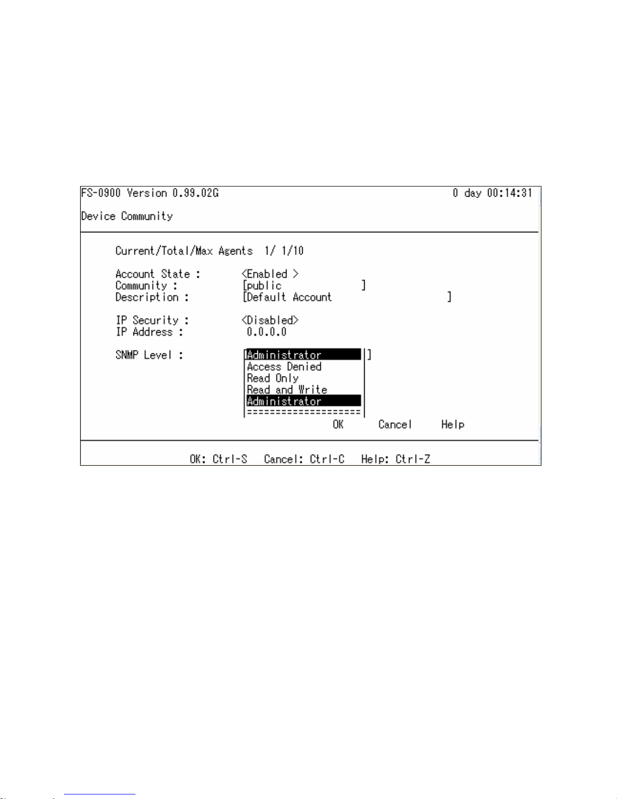
2.7.4 Device Community............................................................................................... 24
2.7.5 Trap Destination................................................................................................... 26
2.7.6 Trap Configuration ............................................................................................... 27
2.8 Switch Management................................................................................................... 28
2.8.1 Switch Configuration............................................................................................ 29
2.8.2 Priority and Rate limit Configuration .................................................................... 30
2.8.3 Port Configuration................................................................................................ 32
2.8.4 VLAN Configuration ............................................................................................. 33
2.8.4.1 Port Based VLAN Configuration.................................................................... 34
2.8.4.2 802.1Q VLAN Concept.................................................................................. 36
2.8.4.3 802.1Q VLAN configuration........................................................................... 39
2.8.4.4 Configuration Default Port VLAN ID.............................................................. 41
2.9 Switch Monitor............................................................................................................ 43
2.9.1 Switch Port State ................................................................................................. 44
2.9.2 Port Traffic Statistics............................................................................................ 45
2.9.3 Port Packet Error Statistics.................................................................................. 46
2.9.4 Port Analysis Statistics ........................................................................................ 48
2.9.5 MAC address table .............................................................................................. 49
2.10 System Utility............................................................................................................ 50
2.10.1 Ping ................................................................................................................... 52
2.10.2 Event Log........................................................................................................... 53
2.10.3 Update Firmware ............................................................................................... 54
2.10.4 Load Factory Setting.......................................................................................... 55
2.10.5 Load Factory Setting Except Network Configuration ......................................... 56
2.11 Save Configuration ................................................................................................... 57
2.12 Reset System........................................................................................................... 58
2.13 Logout ...................................................................................................................... 59
3. SNMP NETWORK MANAGEMENT................................................................................60
3

1. INTRODUCTION
Thank you for using the 7x10/100TX plus 2x100FX managed converter switch. The built-in
management module allows user to configure this managed converter switch and monitor
the operation status locally or thru network remotely.
1.1 Management Options
LED
Fig. 1 Front Panel
RS-232
Duplex SC
Connector
Fig. 2 Back Panel
Management switch are available options are listed below:
• Local Console Management
• Telnet Management
• SNMP Management
Local Console Management
Local Console Management is done through the RS-232 DB-9 console port located at the
front of the converter switch. Direct RS-232 cable connection between the PC and the
converter switch is required for this type of management.
Telnet Management
Telnet is done through the network. Once the converter switch is on the network with proper
configuration, you can use Telnet to log in and monitor the status remotely.
SNMP Management
SNMP is also done over the network. Besides standard MIB (Management Information
Bases), an additional private MIB is also provided for SNMP-based network management
system to compile & control.
4

1.2 Management Software & Interfaces
Following list the choices of management software and interfaces:
• Converter switch Console Program
• SNMP-based management software
Console Program
The converter switch has a built-in, menu-driven interface called the Console Program that
you can use to:
• Configure the system
• Monitor the status
• Reset the system
You can use this Console Program as your only management system. However, other
network management option – SNMP based management system is also available.
You can access the text-mode Console Program locally by connecting a VT100 terminal - or
a workstation running VT100 emulation software - to the converter switch RS-232 DB-9
console port directly. Or, you can use Telnet to login and access the Console Program
through network connection remotely.
SNMP Management Systems
You can use standard SNMP based network management system to manage the converter
switch through the network remotely.
When you use a SNMP based network management system, the converter switch becomes
one of the managed devices (network elements) in that system. The converter switch
management module contains an SNMP agent that will respond to the requests from the
SNMP based network management system. These requests, which you can control, can
vary from getting system information to setting the device attribute values.
The converter switch private MIB is provided for installation into your SNMP based network
management system.
5

1.3 Management Preparations
After you have decided how to manage your converter switch, you need to make the cable
connection, determine the converter switch IP address and, in some cases, install MIB
shipped with your converter switch.
Connecting the converter switch
It is extremely important that cables have the correct pin arrangement and that the proper
cables be used when connecting converter switch to another switches, hubs, workstations,
etc.
100Base-FX Fiber Port
2x100Base-FX Fiber port is located at the front of the converter switch. This port is
primarily used for up-link connection and will always operate at 100M/Full Duplex
mode. Duplex SC or WDM Simplex SC types of connectors are available. Use
proper multimode or single-mode optical fiber to connect this port with other Fast
Ethernet Fiber port.
10/100Base-TX RJ-45 Ports
7x10/100Base-TX RJ-45 ports are also located at the front of the converter switch.
These RJ-45 ports allow user to connect their traditional copper based Ethernet/Fast
Ethernet devices into network. All these ports support auto-negotiation and
MDI/MDIX auto-crossover, i.e. either crossover or straight through CAT-5 cable may
be used.
RS-232 DB-9 Port
The RS-232 DB-9 port is located at the front of the converter switch. This DB-9 port is
used for local, out-of-band management. Since this DB-9 port of the converter switch
is DTE, a null modem is also required to connect the converter switch and the PC.
By connecting this DB-9 port, user can configure & check the converter switch even
the network is down.
IP Addresses
IP addresses have the format n.n.n.n, for example 168.168.1.100.
IP addresses are made up of two parts:
• The first part (168.168 in the example) refers as network address identifies the
network on which the device resides. Network addresses are assigned by three
allocation organizations. Depending on your location, each allocation organization
assigns a globally unique network number to each network that wishes to connect to
the Internet.
• The second part (8.100 in the example) identifies the device within the network.
Assigning unique device numbers is your responsibility. If you are unsure of the IP
6

addresses allocated to you, consult the allocation organization from which your IP
addresses were obtained.
Remember that no two devices on a network can have the same address. If you connect to
the outside, you must change all the arbitrary IP addresses to comply with those you have
been allocated by the allocation organization. If you do not do this, your outside
communications will not operate.
A subnet mask is a filtering system for IP addresses. It allows you to further subdivide your
network. You must use the proper subnet mask for proper operation of a network with
subnets defined.
MIB for Network Management Systems
Private MIB (Management Information Bases) is provided for managing the converter switch
through the SNMP based network management system. You must install the private MIB
into your SNMP based network management system first.
The MIB file is shipped together with the converter switch. The file name extension is ".mib",
which SNMP based compiler can read.
7

2. CONSOLE PROGRAM
This chapter describes how to use your converter switch Console Program, specifically in:
• Local Console Management (out-of-band)
• Telnet Management (in-band)
• Configuring the system
• Resetting the system
The interface and options are the same with Local Console and Telnet Management. The
difference is the type of connection and the port that is used to manage the converter switch.
2.1 Local Console Management
Local Console Management is always done through the RS-232 DB-9 port and requires a
direct connection between the converter switch and a PC. This type of management is very
useful especially when the network is down and the converter switch cannot be reached by
any other means.
You also need to use the Local Console Management to setup the converter switch network
configuration for the first time. You can setup the IP address and change the default
configuration to desired setting to enable Telnet or SNMP services.
Follow these steps to begin a management session using Local Console Management:
1. Attach the serial cable the RS-232 DB-9 port located at the front of the converter
switch with a null modem.
2. Attach the other end to the serial port of a PC or workstation.
3. Run a terminal emulation program using the following settings:
• Emulation VT-100/ANSI compatible
• BPS 9600
• Data bits 8
• Parity None
• Stop bits 1
• Flow Control None
• Enable Terminal keys
4. Press Enter to reach the Main menu.
8

2.2 Remote Console Management - Telnet
You can manage the converter switch via Telnet session. However, you must first assign a
unique IP address to the converter switch before doing so. Use the Local Console to log
into the converter switch and set up the IP address for the first time.
Follow these steps to manage the converter switch through Telnet session:
1. Use Local Console to set up the assigned IP parameters of the converter switch,
• IP address
• Subnet Mask
• Default gateway IP address, if required
2. Run Telnet.
3. Log into the converter switch to reach the Main menu.
Limitations
When using Telnet, keep the following in mind:
• Only two active Telnet sessions can access the converter switch at one time.
9

2.3 Console Program Overview
Once you gain the access, a Login Console appear as following,
Enter the user name and password then press ENTER to login to the Console Program
main menu,
Press Tab or or or Number directly to select.
1. System Information: Name the converter switch, specify the location and check the
current version information.
2. User Authentication: View the registered user list. Add a new user or remove an
existing user.
10

3. Network Management: Set up or view the IP address and related information of the
converter switch required for network management application.
4.
Switch Management: Setup switch/port configuration, VLAN configuration and other
functions.
5. Switch Monitor: View the operation status and traffic statistics of the ports.
6. System Utility: Ping, Firmware Upgrade, Load Factory Setting, …etc.
7. Save Configuration: Save all change to the system.
8. Reset System: Reset converter switch.
9. Logout: Logout from the console program.
0. Help: List the console operation keys.
11

2.4 Navigating the Console Program Screens
To do this… Use this key…
Highlight an option in menu. Tab and or or press number
directly
Select a highlighted option. Enter
Pull Down Menu in a choice field. Spacebar
Select within Pull Down Menu in a choice field. or
Toggle between available options in a choice field. Spacebar
Move to the next entry field or command. Tab
Move one line up to the previous field. <−
Move one line down to the next field. −>
Exit current screen ESC
Field Types
A typical console program screen contains several types of fields, as shown in below figure.
-
-
-
-
-
12
1. Timer: X day XX:XX:XX
Timer is view-only, shows how long the switch has been up since it was turned on or reset.
2. Pull Down Menu: [ XXXX |]
Pull down menu is used if there are more than 2 selections, for example: Port Number
Press Spacebar will display the pull down menu as below.
Use or move to desired selection and then press Spacebar to select.
3. Toggle Option:
<
XXXX >
A Toggle option contains 2 selections, for example: Account State
Press Spacebar to select between
<
Enable > & < Disabled
>
4. Editing Field: [ XXXX ]
Options may be edited directly, for example: Community
Use Backspace to delete default setting and enter new content directly.
5. View Only Field: XXXX
No options available and is view only,
For example: Current number of each registered user.
6. OK
Press OK to accept change and quit the current menu.
13

7. Cancel
Press Cancel to skip the change and quit the current menu.
8. Help
Press Help to view On-Line help as below,
This pop up message alerts user that the configuration change will take effect after reset.
However, before perform System Reset, user must save the configuration change first.
14

2.5 System Information
Select System Information in the Console Program Main menu, following screen appears.
Company Name: Enter a company name for this converter switch, up to 55 alphanumeric
characters.
System Object ID: View only field, predefined System OID.
System Contact: Enter contact information for this converter switch, up to 55 alphanumeric
characters.
System Name: Enter a unique name for this converter switch, up to 55 alphanumeric
characters. Use a descriptive name to identify the converter switch in relation to your
network, for example “Backbone 1”. This name is mainly used for reference purpose only.
System Location: Enter a brief description of the converter switch location, up to 55
alphanumeric characters. Like the name, the location is for reference only, for example “13th
Floor”.
Model Name: View only field shows the product model name.
Firmware Version: View only field shows the product firmware version.
ROM size <KB>: View only field shows the product ROM size.
FLASH size <KB>: View only field shows the product FALSH size.
15

RAM size <KB>: View only field shows the product RAM size.
Fiber Port: View only field shows the fiber port number and fiber port perimeters.
- 1310 fiber transceiver operation wavelength (nm)
- SC fiber transceiver connector type
- 2KM fiber transceiver operation length
TP Port: View only field shows the total TP port number.
Boot ROM Version: View only field shows the Boot ROM version.
OS Version View only field shows the OS version.
UI Version View only field shows the User Interface program version.
CPU Version View only field shows the CPU version.
M/B Version View only field shows the Main board version.
16

2.6 User Authentication
To prevent any un-authorized operation, only registered users are allowed to operate the
converter switch. Any user wants to operate the converter switch need to register into the
user list first.
To view or change current registered users, select 2. User Authentication from the main
menu, following screen appears.
Up to 10 Users maybe set.
Press New to add a new user.
Press Edit to view the current user setting.
Use Delete to remove a registered user.
Following screen appears,
17

Current/Total/Max Users: View only field. Specify:
Current: Current registered user number.
Total: Total registered user number.
Max Users: Maximum available registered user number, default 10.
Account State: Press Spacebar to Enable or Disable this User Account.
User Name: Specified the authorized user login name, up to 20 alphanumeric characters.
Password: Enter desired user password, up to 20 alphanumeric characters.
Retype Password: Enter password again for double check.
Description: Enter a unique description for the User, up to 35 alphanumeric characters.
This is mainly for reference purpose only.
IP Security: Press Spacebar to Enable or Disable the IP security function.
If Enable, user may access the converter switch only through the management station which
has exact IP address specified in below IP address field.
If Disable, user may access the converter switch through any station.
IP Address: Specify the IP address used for IP Security function.
Console Level: Use or to select desired privilege for the console operation
Available operation privileges,
Administrator Full access right include maintain user account & system information,
load factory setting, etc.
18
 Loading...