

CTS WPC-2012 SERIES, MPC-2012 SERIES User Manual
Trademarks
CTS is a registered trademark of Connection Technology Systems Inc.. Contents
subject to revision without prior notice. All other trademarks remain the property of their
owners.
Copyright Statement
Copyright Connection Technology Systems Inc.
This publication may not be reproduced as a whole or in part, in any way whatsoever
unless prior consent has been obtained from Connection Technology Systems Inc..
FCC Warning
WPC/MPC-2012 Series Media Converters have been tested and found to comply with
the limits for a Class A digital device, pursuant to Part 15 of the FCC Rules. These
standards are designed to provide reasonable protection against harmful interference
when these devices are operated in a commercial environment. These devices generate,
use, and can radiate radio frequency energy and may cause harmful interference to
radio communications unless installed in accordance with this User’s Guide. Operation f
these devices in a residential area is likely to cause harmful interference which will make
the user responsible for the appropriate remedial action at his / her own expense.
CE Mark Warning
These are Class A products. In a domestic environment these products may cause radio
interference in which case the user will need to consider adequate preventative
methods.
1. Checklist
The package should contain the following items:
-
WPC/MPC-2012 Media Converter
-
Power Adapter (Optional)*
-
User’s Guide
* For detailed information, please see Section 9.
Please notify your sales representative immediately if any item is
missing or damaged.
2. Overview
WPC/MPC-2012 Media Converters support IEEE802.3at PoE
feature and are specifically designed to supply power to
PoE-enabled devices such as WiFi AP or surveillance cameras.
WPC/MPC-2012 Media Converters are power supply equipments
(PSE) that can transmit data and supply power at the same time
to the powered devices (PD). The maximum cable distance that
can reach the powered devices from WPC/MPC-2012 is up to
100M, allowing your powered devices to be installed in a place
where power is not easily accessible. Besides, WPC/MPC-2012
Series Media Converters aim at industrial applications that
demand wide range of operating temperature and require
redundant power supplies to create a reliable and stable
networking environment in the event of power failure. They can
also be mounted on the wall or onto 35mm DIN rail using DIN rail
clip on the media converter. The installation and operation
procedures are simple and straightforward. Operation status can
be locally monitored through a set of diagnostic LED indicators
located on the front panel.
Major Features:
-
Auto-Negotiation in TP port
-
Store and Forward Switching Mechanism
-
Support MDI/MDIX Auto-Crossover
-
Support Flow Control
-
Support Link Alarm
-
Support fault alarms for power and port failure
-
Support 1K MAC address
-
Support 9K bytes Jumbo Frame
-
Support redundant AC and DC power supply
-
Support wide range of operating temperature (-20oC ~60oC)
-
Support DIN Rail and Wall Mounting
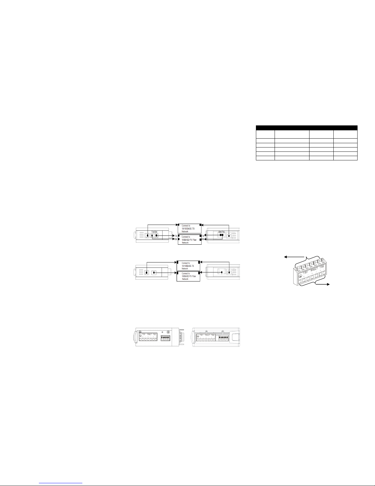
3. Network Installation
-
Attach fiber cable from the converter to the fiber network.
-
Attach a UTP cable from the 10/100Base-TX network to
the RJ-45 port on the converter.
-
Connect the power adapter to the converter and check that
the Power LED lights up. The TP Link/ACT and F/O
Link/ACT LED will light when all the cable connections are
satisfactory.
Figure 1. Basic Network Connection for BTFX models
Figure 2. Basic Network Connection for WDM/SFP models
4. DIP SWITCH Setting
WPC-2012 Series Media Converters provide users with a DIP
Switch to configure switching functions. The DIP Switch is located at
the bottom panel of the media converter and the default setting of all
pins is set to OFF.
MPC-2012 WPC-2012
Figure 3. Terminal Block and DIP Switch (Bottom Panel)
Pin NO.
Function
OFF
ON
1
TP port
Auto-negotiation
Enable
Disable
2
TP Speed
100Mbps
10Mbps
3
Duplex mode
Full Duplex
Half Duplex
4
Link Alarm
Disable
Enable
5
F/O Fault Alarm
Disable
Enable
6
TP Fault Alarm
Disable
Enable
NOTE: Please perform Power On reset after modifying the DIP
Switch setting.
5. Terminal Block
TB1 and TB2 Power Supply: There are two pairs of power
supply connection (TB1 and TB2) on the terminal block for
power redundancy purpose. You can use both pairs of power
supply (TB1 and TB2) or use either one pair of power supply on
the terminal block and AC external power supply to create
redundant setup. The redundant power supply will take over
seamlessly when one power source is down to protect your
device or network from the loss of power. When you use only
one power supply (no redundant power is available), the LED
Power/Port Status will flash in orange to alert the user.
Port Fault Alarm: One pair of port fault connection on the
terminal block is used to connect alarm devices such as
speakers or LEDs to alert users when TP or F/O port link is
disconnected. To make this function work, you must first set pin
5 and 6 on the DIP Switch to ON position (Enable).
Figure 4. Terminal Block Front and Top View
6. Link Alarm
Link Alarm allows users to easily identify and diagnose the linking
status. If Link Alarm DIP switch is set to Enable, TP and F/O can
link up only when both linking conditions are good. In addition, if
the TP or F/O port link is down during operation, the other port will
also be turned down to alert the user. Setting Link Alarm DIP
switch to Enable gives the user a transparent link indication
between two network devices interconnected by WPC-2012.
If Link Alarm is disabled, the TP and F/O will link up based on their
individual linking condition. Furthermore, if either port link (TP or
F/O) is down during operation, it will not turn down the other port
link.
Use flat-head
screwdriver to
loosen and tighten
the screw.
Insert positive or
negative wire as
indicated.
WPC-2012
MPC-2012
WPC-2012
MPC-2012
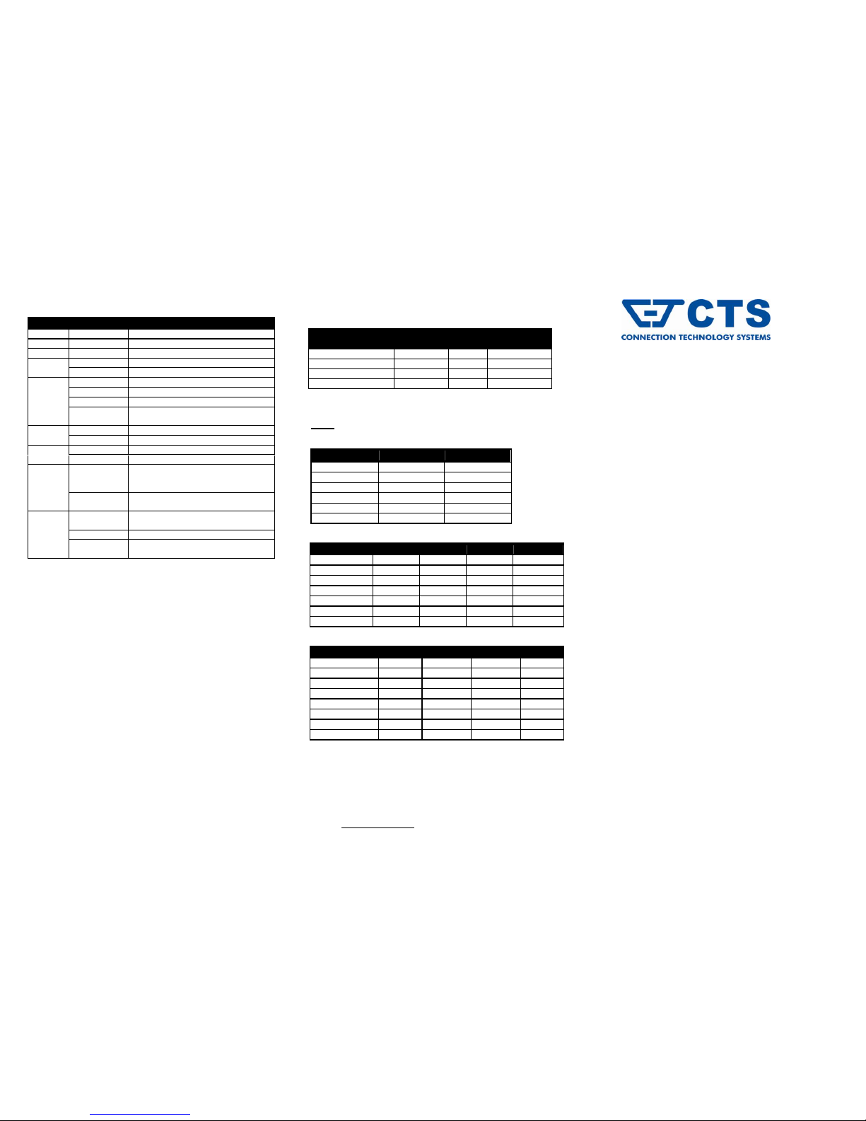
7. LED Description
8. Technical Specifications
Standards
IEEE 802.3, 802.3u, 802.3x, 802.3at
Interface
1 X 10/100 RJ-45 connector
1 X 100 SC/ST F/O port or SFP slot
LED
PW ADC, PW T1, PW T2, FDX, PWR/Port
Status, Speed, F/O Link/ACT, TP Link/ACT, PoE
Power
DC Input Voltage: 48VDC
DC Power Jack x 1; DC Terminal Block x 2
Shipping Weight
WPC-2012: 0.295KG ; MPC-2012: 0.5KG
Dimensions
WPC-2012:105mm(W)X93mm(D)X35mm(H)
MPC-2012:105mm(W)X93mm(D)X35mm(H)
Temperature
Operating: -20oC ~60oC
Storage: -20oC ~70oC
Humidity
5%~90% RH non-condensing
EMC Safety
FCC Part 15 Class A, CE
Media
TP:
EIA/TIA-568 CAT 5e
Fiber:
50/125, 62.5/125um multi-mode fiber
9/125, 10/125um single-mode fiber
*Please contact us for further reports and updates.
9. Optional Accessory
Adapters:
Fiber Transceiver Information
100M
Multi-Mode
TYPE
BTFC
BTFT
Connector Type
SC
ST
Wavelength
1310nm
1310nm
Typical Distance
2Km
2Km
Min/Max TX PWR
-20.0dBm/-14.0dBm
-20.0dBm/-14.0dBm
Sensitivity
-31.0dBm
-31.0dBm
Link Budget
11.0dB
11.0dB
Single-Mode
TYPE
BTFC(SM-30)
BTFC(SM-50)
BTFC(SM-80)
BTFC(SM-100)
Connector Type
SC
SC
SC
SC
Wavelength
1310nm
1310nm
1310nm
1550nm
Typical Distance
30Km
50Km
80Km
100Km
Min TX PWR
-15.0dBm
-5.0dBm
0dBm
-5.0dBm
Max TX PWR
-8.0dBm
0dBm
5.0dBm
0dBm
Sensitivity
-34.0dBm
-35.0dBm
-36.0dBm
-35.0dBm
Link Budget
19.0dB
30.0dB
36.0dB
30.0dB
Wave-Length WDM
TYPE
W2A(SM-20)
W2B(SM-20)
W2A(SM-40)
W2B(SM-40)
Connector Type
SC
SC
SC
SC
TX Wavelength
1310nm
1550nm
1310nm
1550nm
RX Wavelength
1550nm
1310nm
1550nm
1310nm
Typical Distance
20 Km
20 Km
40 Km
40 Km
Min TX PWR
-14.0dBm
-14.0dBm
-8.0dBm
-8.0dBm
Max TX PWR
-8.0dBm
-8.0dBm
0dBm
0dBm
Sensitivity
-31.0dBm
-31.0dBm
-34.0dBm
-34.0dBm
Link Budget
17.0 dB
17.0 dB
26.0 dB
26.0 dB
NOTE: Specifications may change without prior notice.
Contact Information
Connection Technology Systems INC (CTS)
18F-6, No.79, Sec.1, Xintai 5th Rd., Xizhi Dist.,
New Taipei City 221, TAIWAN, R.O.C.
TEL: +886 2 26989661 FAX: +886 2 26989662
E-Mail: info@ctsystem.com
WPC-2012/MPC-2012
SERIES
10/100Base-TX to
100Base-FX Fast Ethernet
Media Converter with
Built-in IEEE802.3at
PoE/PSE Feature and
Extended Operating
Temperature
User’s Guide
Version 1.4
LED
Color
Function
PW ADC
Green
AC or DC power is available.
PW T1
Green
Terminal Block 1 powers up.
PW T2
Green
Terminal Block 2 powers up.
TP
Link/ACT
Green
TP link is up.
Green Blinking
TP is receiving and transmitting data.
Speed
Off
Link is down or TP works in 10M.
Green
TP works in 100M.
Orange
TP works in 1000M.
Green/Orange
Blinking
TP is receiving and transmitting data.
FDX
Off
TP port works in half duplex mode.
Green
TP port works in full duplex mode.
F/O
Link/ACT
Green
F/O link is up.
Green Blinking
F/O is receiving and transmitting data.
PWR/Port
Status
Orange
TP or F/O link is down. (This indication
only works when DIP 9 and 10 are set to
Enable.)
Orange
Blinking
Redundancy system is abnormal (only
one power source is available).
PoE
Green
Device provides power and works
normally.
Green Blinking
Device does not provide power.
Fast Green
Blinking
Device’s PoE function is working
abnormally.
MODEL
Connector
Type
Volt/Watt
PSE Power
Feeding Function
WAP-POWER-12J18
DC Jack
12V/18W X WAP-POWER-48J90
DC Jack
48V/90W
O
WAP-POWER-48D75
Terminal Block
48V/75W
O
WAP-POWER-48D240
Terminal Block
48V/240W
O
 Loading...