

Trademarks
CTS is a registered trademark of Connection Technology
Systems Inc. Contents are subject to revision without prior
notice.
All other trademarks remain the property of their owners.
Copyright Statement
Copyright Connection Technology Systems Inc.
This publication may not be reproduced as a whole or in
part, in any way whatsoever unless prior consent has been
obtained from Connection Technology Systems Inc.
FCC Warning
This equipment has been tested and found to comply with
the limits for a Class-A digital device, pursuant to Part 15 of
the FCC Rules These standards are designed to provide
reasonable protection against harmful interference when
these devices are operated in a commercial environment.
These devices generate, use, and can radiate radio
frequency energy and may cause harmful interference to
radio communications unless installed in accordance with
this User’s Guide. Operation of these devices in a
residential area is likely to cause harmful interference
which will make the user responsible for the appropriate
remedial action at his / her own expense.
CE Mark Warning
These are Class A products. In a domestic environment
these products may cause radio interference in which case
the user will need to consider adequate preventative
methods.
1. Checklist
The MCT-100 carton should contain following items:
-
MCT-100 Converter
-
AC-DC Power Adapter
Please notify your sales representative immediately if any
items are missing or damaged.
2. Overview
Connection Technology Systems (CTS) MCT-100 series
media converter are the Ethernet 10/100Base-T to
100Base-X media converter. The MCT-100 series media
converter converts traditional twisted-pair RJ-45 cable into
various fiber media including multi-mode, single-mode,
SC/ST/MR connector, or bi-directional wdm and extends
transmission distance for the deployment to the household,
apartment or campus.
Major Features:
-
Comply with IEEE 802.3, 802.3u
-
10/100Base-TX to 100Base-FX Converter
-
Store & Forward Switching Mechanism
-
MDI/MDI-X Auto-Crossover supported
-
Auto-Negotiation or Manual mode setting of Speed
& Duplex mode
- Link Alarm function
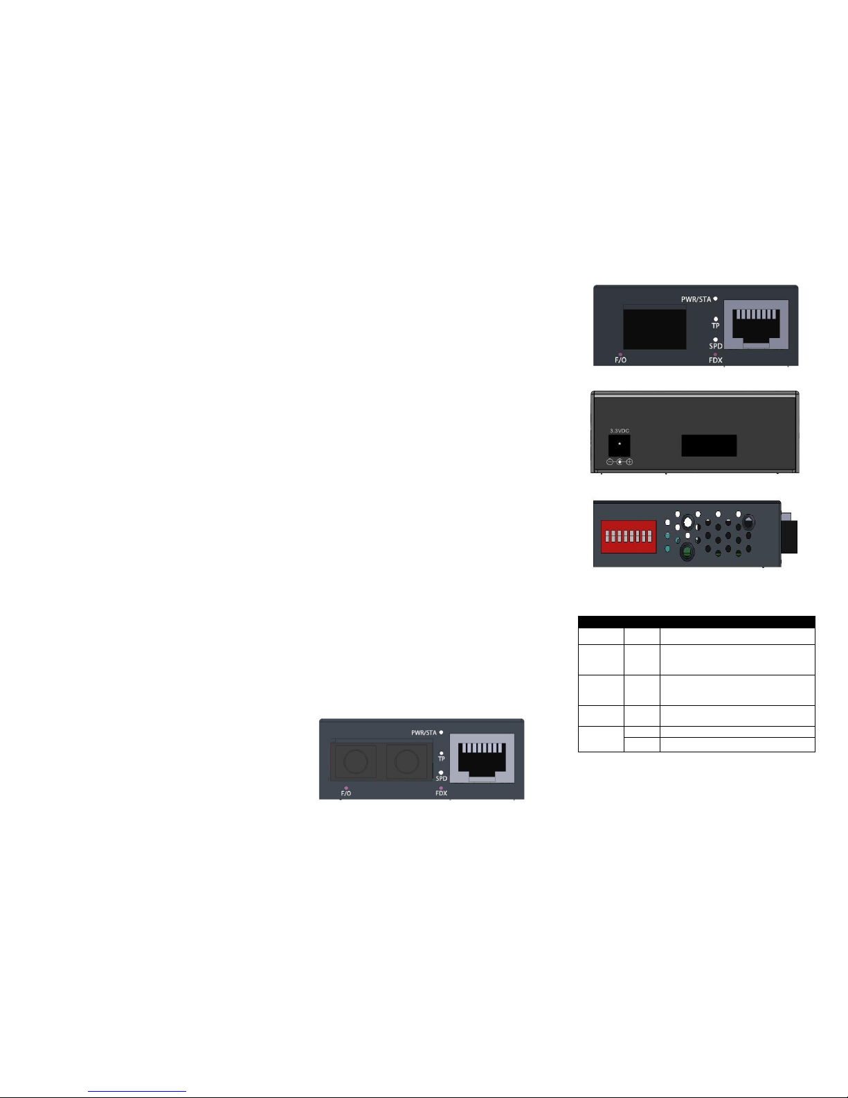
3. Installation
The installation procedure is simple and straightforward.
-
Attach fiber cable from the MCT-100 to the fiber
network.
-
Attach a UTP cable from the 10/100Base-TX
network to the RJ-45 port on the MCT-100.
-
Connect the power adapter to the MCT-100 and
check that the PWR/STA lights up. The TP Link and
F/O LED will light when all the cable connections are
satisfactory.
Figure 1. Dual fiber Front Panel
Figure 2. WDM & SFP Front Panel
Figure 3. Rear Panel
Figure 4. Side Panel
4. LED Description
LED
Color
Function
PWR/STA
Green
Lit when power is available.
TP
Green
Lit when TP cable connection with
remote device is good.
Blink when TP traffic is present.
F/O
Green
Lit when Fiber cable connection at
100M with remote device is good.
Blink when F/O traffic is present.
FDX
Green
Lit when TP works in Full-Duplex.
Not-Lit when TP works in Half-Duplex.
SPD
Off
Lit when TP works in 10M.
Green
Lit when TP works in 100M.
5. DIP Switch Setting
The default setting for PIN 1 to PIN 8 is OFF.
Pin NO.
Function
OFF
ON
1
TP Auto-Negotiation
Enable
Disable 2 TP speed
100M
10M 3 TP Duplex
Full
Half 4 Link Alarm
Disable
Enable 5 N/A
N/A
N/A 6 N/A
N/A
N/A 7 N/A
N/A
N/A 8 N/A
N/A
N/A
NOTE:
1. Before adjusting the configuration of the Dip Switch, the
power should be unplugged.
2. For the best link capability (10/100M, FDX/HDX), Pin 1, 2
and 3 are set to OFF for enabling TP Auto-Negotiation.
3. If Pin 2 is set to ON (10M) while Pin 1 and 3 are set to
OFF, the link capability is 10M FDX/HDX.
4. If Pin 3 is set to ON (Half) while Pin 1 and 2 are set to
OFF, the link capability is 10/100M HDX.
5. If Pin 2 & 3 are both set to ON, the link capability is 10M
HDX.
6. Auto-Negotiation MUST be enabled (Pin 1 must be OFF)
before enabling Link Alarm (Pin 4 is ON).
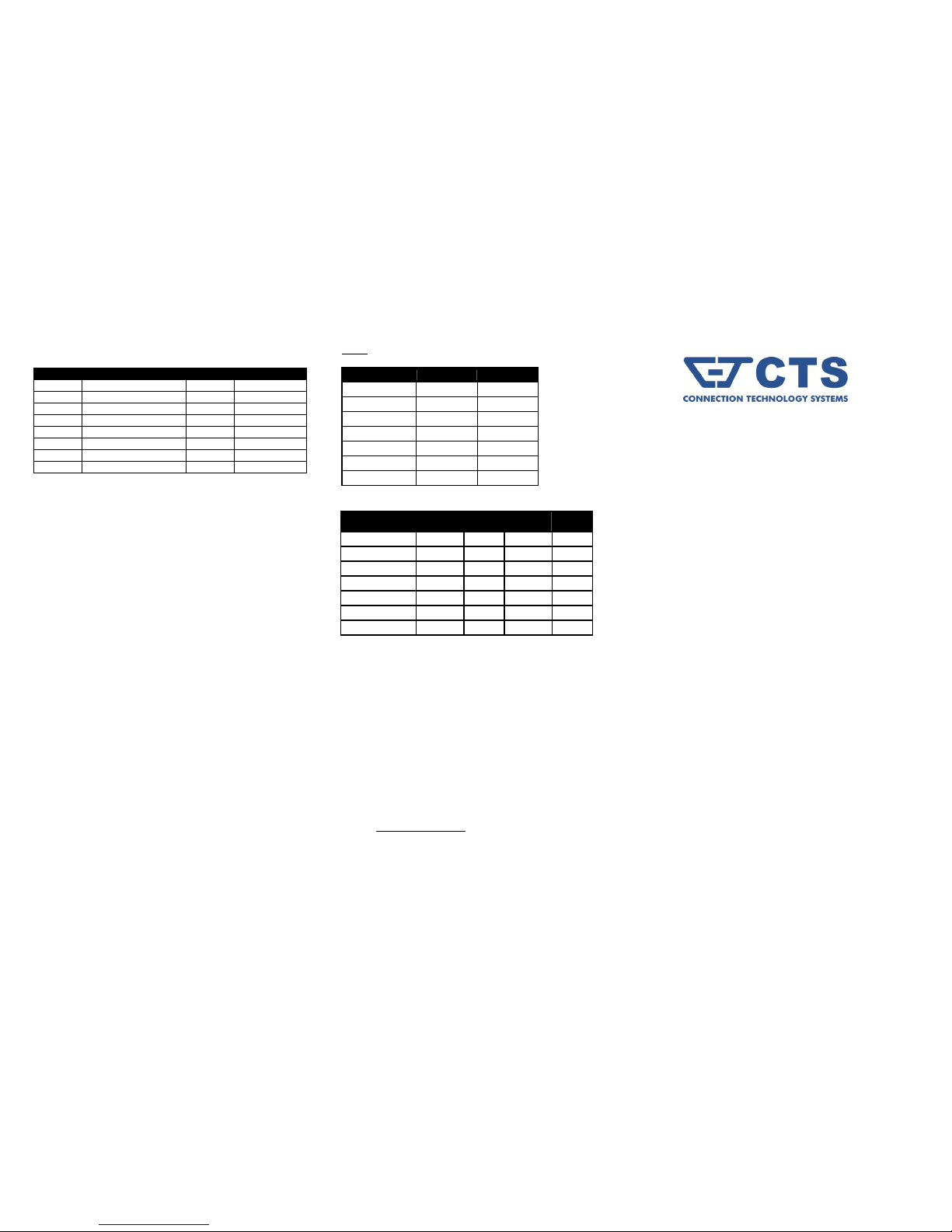
6. Technical Specifications
Standards
IEEE 802.3 & IEEE 802.3u
Switching Mechanism
Store & Forward
MAC Table
1K Entries
Forward & Filter Rate
(64 Bytes)
10Base-T 14,800 pps
100Base-TX 148,800 pps
LED
Power/Status, TP, Speed, FDX,
F/O
Power
DC 3.3V
Power Consumption
1.9W
Weight
0.1Kg
Dimensions
51mm x 74mm x 20mm (WxDxH)
Temperature
Operating: 0 ~ 50 oC
Storage: -20 ~ 60 oC
Humidity
5% ~ 90% RH
Certification
FCC/CE Class A
UTP
Cat. 5 UTP cable
Fiber 50/125, 62.5/125, or 100/140m multi-mode
8.3/125, 8.7/125, 9/125 or 10/125m single-mode
Fiber Transceiver Information
100M
Multi-Mode
TYPE
BTFC
BTFT
Connector Type
SC
ST
Wavelength
1310nm
1310nm
Typical Distance
2Km
2Km
Min TX PWR
-20.0dBm
-20.0dBm
Max TX PWR
-14.0dBm
-14.0dBm
Sensitivity
-31.0dBm
-31.0dBm
Link Budget
11.0dB
11.0dB
Single-Mode
TYPE
BTFC
(SM-30)
BTFC
(SM-50)
BTFC
(SM-80)
BTFC
(SM-100)
Connector Type
SC
SC
SC
SC
Wavelength
1310nm
1310nm
1310nm
1550nm
Typical Distance
30Km
50Km
80Km
100Km
Min TX PWR
-15.0dBm
-5.0dBm
0dBm
-5.0dBm
Max TX PWR
-8.0dBm
0dBm
5.0dBm
0dBm
Sensitivity
-34.0dBm
-35.0dBm
-36.0dBm
-35.0dBm
Link Budget
19.0dB
30.0dB
36.0dB
30.0dB
NOTE: Specifications may change without prior notice.
Contact Information
Connection Technology Systems INC (CTS)
18F-6, No.79, Sec.1, Xintai 5th Rd., Xizhi Dist.,
New Taipei City 221, TAIWAN, R.O.C.
TEL: +886 2 26989661 FAX: +886 2 26989662
E-Mail: info@ctsystem.com
MCT-100 Series
10/100BASE-TX to
100BASE-FX Standalone
Media Converter
User’s Guide
Version 1.0
 Loading...