

CTS HES-3109 Series User Manual

1
HES-3109 SERIES
9 PORTS 10/100/1000BASE-T ETHERNET MANAGED SWITCH
8 PORTS 10/100/1000BASE-T ETHERNET MANAGED SWITCH
WITH 1 PORT 1000BASE-X UPLINK OR 1 PORT
100/1000BASE-X UPLINK
8 PORTS 10/100/1000BASE-T ETHERNET MANAGED SWITCH
WITH 1 PORT 1000BASE-X UPLINK OR 1 PORT
100/1000BASE-X UPLINK AND TV RF RECEIVER
8 PORTS 10/100/1000BASE-T ETHERNET MANAGED SWITCH
WITH 1 PORT 1000BASE-X UPLINK OR 1 PORT
100/1000BASE-X UPLINK WITH BATTERY CHARGING
FUNCTION
8 PORTS 10/100/1000BASE-T ETHERNET MANAGED SWITCH
WITH 1 PORT 1000BASE-X UPLINK OR 1 PORT
100/1000BASE-X UPLINK WITH BATTERY CHARGING
FUNCTION AND TV RF RECEIVER
Network Management
User’s Manual
Version 1.0

2
Trademarks
Contents subject to revision without prior notice.
All other trademarks remain the properties of their owners.
Copyright Statement
This publication may not be reproduced as a whole or in part, in any way whatsoever unless prior consent has been obtained
from the owner.
FCC Warning
This equipment has been tested and found to comply with the limits for a Class A digital device, pursuant to Part 15 of the
FCC Rules. These limitations are designed to provide reasonable protection against harmful interference in a residential
installation. This equipment generates, uses and can radiate radio frequency energy and, if not installed and used in
accordance with the instructions, may cause harmful interference to radio communications. However, there is no guarantee
that interference will not occur in a particular installation. If this equipment does cause harmful interference to radio or
television reception, which can be determined by turning the equipment off and on, the user is encouraged to try to correct
the interference by one or more of the following measures:
Reorient or relocate the receiving antenna.
Increase the separation between the equipment and receiver.
Connect the equipment into an outlet on a circuit different from that to which the receiver is connected.
Consult your local distributors or an experienced radio/TV technician for help.
Shielded interface cables must be used in order to comply with emission limits.
Changes or modifications to the equipment, which are not approved by the party responsible for compliance, could affect the
user’s authority to operate the equipment.
Copyright © 2011 All Rights Reserved.
Company has an on-going policy of upgrading its products and it may be possible that information in this document is not
up-to-date. Please check with your local distributors for the latest information. No part of this document can be copied or
reproduced in any form without written consent from the company.
Trademarks:
All trade names and trademarks are the properties of their respective companies.

3
Table of Content
1. INTRODUCTION ............................................................................................................... 6
1.1 Interfaces...................................................................................................................... 6
1.2 Management Preparations ........................................................................................... 8
1.2.1 Connecting the Managed Switch ........................................................................... 8
1.2.2 Assigning IP Addresses ......................................................................................... 9
1.3 LED Definitions ........................................................................................................... 10
1.4 Button Definitions ....................................................................................................... 10
2. Command Line Interface (CLI) ...................................................................................... 11
2.1 Remote Console Management-Telnet ........................................................................ 11
2.2 Navigating CLI ................................................................................................ ............ 12
2.2.1 General Commands ............................................................................................. 12
2.2.2 Quick Keys ........................................................................................................... 13
2.2.3 Command Format ................................................................................................ 13
2.2.4 Login Username & Password .............................................................................. 15
2.3 User Mode .................................................................................................................. 15
2.4 Privileged Mode .......................................................................................................... 16
2.4.1 Copy-cfg Command ............................................................................................. 16
2.4.2 Firmware Command ............................................................................................ 17
2.4.3 Reload Command ................................................................................................ 17
2.4.4 Write Command ................................................................................................... 18
2.4.5 Configure Command ............................................................................................ 18
2.5 Configuration Mode .................................................................................................... 18
2.5.1 Entering Interface Numbers ................................................................................. 19
2.5.2 No Command ....................................................................................................... 19
2.5.3 Show Command .................................................................................................. 19
2.5.4 Interface Command ............................................................................................. 21
2.5.5 CATV Command .................................................................................................. 23
2.5.6 IP Command ........................................................................................................ 23
2.5.7 Loop Detection Command ................................................................................... 26
2.5.8 MAC Command ................................................................................................... 26
2.5.9 Management Command ...................................................................................... 27
2.5.10 NTP Command .................................................................................................. 27

4
2.5.11 QoS Command .................................................................................................. 28
2.5.12 Security Command ............................................................................................ 33
2.5.13 SNMP-Server Command ................................................................................... 35
2.5.14 Switch Command ............................................................................................... 38
2.5.15 Switch-info Command ........................................................................................ 38
2.5.16 User Command .................................................................................................. 39
2.5.17 VLAN Command ................................................................................................ 41
2.5.18 Show interface statistics Command ................................................................... 43
2.5.19 Show sfp Command ........................................................................................... 44
2.5.20 Show log Command........................................................................................... 44
2.5.21 Show running-config & start-up-config Command ............................................. 44
3. WEB MANAGEMENT ..................................................................................................... 45
3.1 System Information .................................................................................................... 47
3.2 User Authentication .................................................................................................... 48
3.3 Network Management ................................................................................................ 50
3.3.1 Network Configuration ......................................................................................... 50
3.3.2 System Service Configuration .............................................................................. 51
3.3.3 Time Server Configuration ................................................................................... 52
3.3.4 Device Community ............................................................................................... 52
3.3.5 Trap Destination ................................................................................................... 54
3.3.6 Trap Configuration ............................................................................................... 54
3.4 Switch Management ................................................................................................... 55
3.4.1 Switch Configuration ............................................................................................ 56
3.4.2 Storm Control ....................................................................................................... 56
3.4.3 Port Configuration ................................................................................................ 57
3.4.4 Rate Limit Configuration ...................................................................................... 58
3.4.5 QoS Priority Configuration ................................................................................... 58
3.4.6 VLAN Configuration ............................................................................................. 60
3.4.6.1 IEEE 802.1q Tag VLAN ................................................................................. 62
3.4.6.1.1 Configure VLAN ...................................................................................... 62
3.4.6.1.2 Configure Default Port VLAN ID ............................................................. 63
3.4.6.2 Q-in-Q VLAN Configuration ........................................................................... 64
3.4.7 IGMP Snooping.................................................................................................... 65
3.4.8 Loop Detection ..................................................................................................... 66

5
3.4.9 Filter Configuration .............................................................................................. 67
3.5 Switch Monitor ................................................................................................ ............ 67
3.5.1 Switch Port State ................................................................................................. 68
3.5.2 Port Counters Rates ............................................................................................ 69
3.5.2.1 Port Traffic Statistics (Rates) ......................................................................... 69
3.5.2.2 Port Packet Error Statistics (Rates) ............................................................... 70
3.5.2.3 Port Packet Analysis Statistics (Rates) ......................................................... 71
3.5.3 Port Counters Events ........................................................................................... 72
3.5.3.1 Port Traffic Statistics (Events) ....................................................................... 72
3.5.3.2 Port Packet Error Statistics (Events) ............................................................. 73
3.5.3.3 Port Packet Analysis Statistics (Events) ........................................................ 74
3.5.4 SFP Information ................................................................................................... 75
3.5.4.1 SFP Port Info ................................................................................................. 75
3.5.4.2 SFP Port State .............................................................................................. 76
3.5.5 IGMP Snooping.................................................................................................... 76
3.5.6 Loop Detection ..................................................................................................... 77
3.5.7 MAC Address Table ............................................................................................. 77
3.6 System Utility .............................................................................................................. 78
3.6.1 Event Log ............................................................................................................. 79
3.6.2 Update ................................................................................................................. 79
3.6.3 Load Factory Settings .......................................................................................... 80
3.6.4 Load Factory Settings Except Network Configuration .......................................... 81
3.7 Save Configuration ..................................................................................................... 81
3.8 Reset System ............................................................................................................. 82
3.9 Logout ........................................................................................................................ 82
APPENDIX A: DHCP Auto-Provisioning Setup ................................................................ 83
6
1. INTRODUCTION
Thank you for using the 8 Ports 10/100/1000Base-T plus 1 Port 1000Base-X or
100/1000Base-X Uplink, or 9 Ports 10/100/1000Base-T Ethernet Managed Switch. The builtin management module allows users to configure this Switch and monitor the operation status
locally or remotely through network.
The Managed Switch is fully compliant with IEEE 802.3 and 802.3u standards. By employing
store and forward switching mechanism, the Switch provides low latency and faster data
transmission. Moreover, it also supports more advanced functions such as QoS, Q-in-Q
VLAN Tunneling, Rate Limiting, IGMP Snooping, etc.. Users can configure the required
settings of the Switch and monitor its real-time operational status via Command Line Interface
(CLI). For detailed descriptions on how to use CLI, please refer to Section 2.
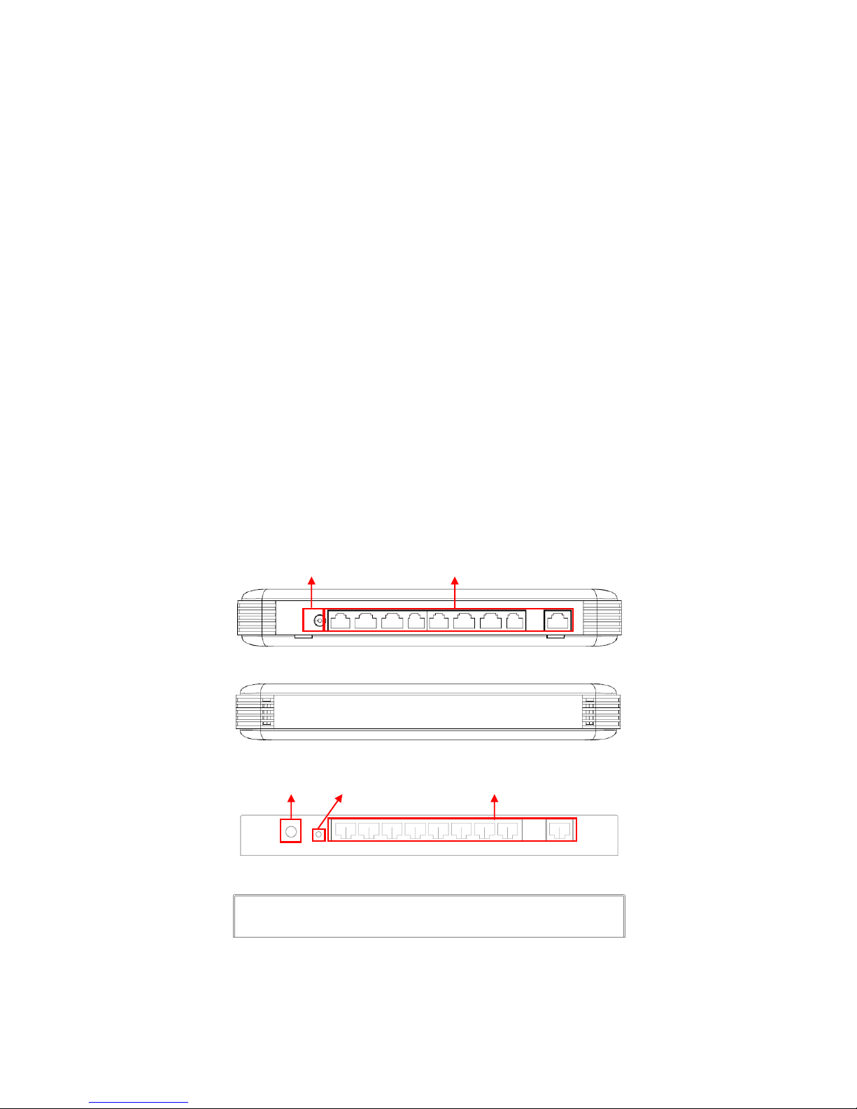
1.1 Interfaces
Depending on the main device and optional accessories that you purchased, the front panel
and rear panel of your Switch may look differently from model to model. Figure 1 to 4 show
the front and rear panel for 9-Port 10/100/1000Base-T Ethernet Managed Switch in stylish
plastic housing or metal housing respectively; whereas, Figure 5 to 8 show the front and rear
panel for 8-Port 10/100/1000Base-T plus 1-Port 1000Base-X or 100/1000Base-X Uplink
Ethernet Managed Switch with optional CATV RF module in stylish plastic housing or metal
housing.
Figure 1. Front Panel for 9-Port 10/100/1000Base-T Managed Switch (plastic housing)
Figure 2. Rear Panel for 9-Port 10/100/1000Base-T Managed Switch (plastic housing)
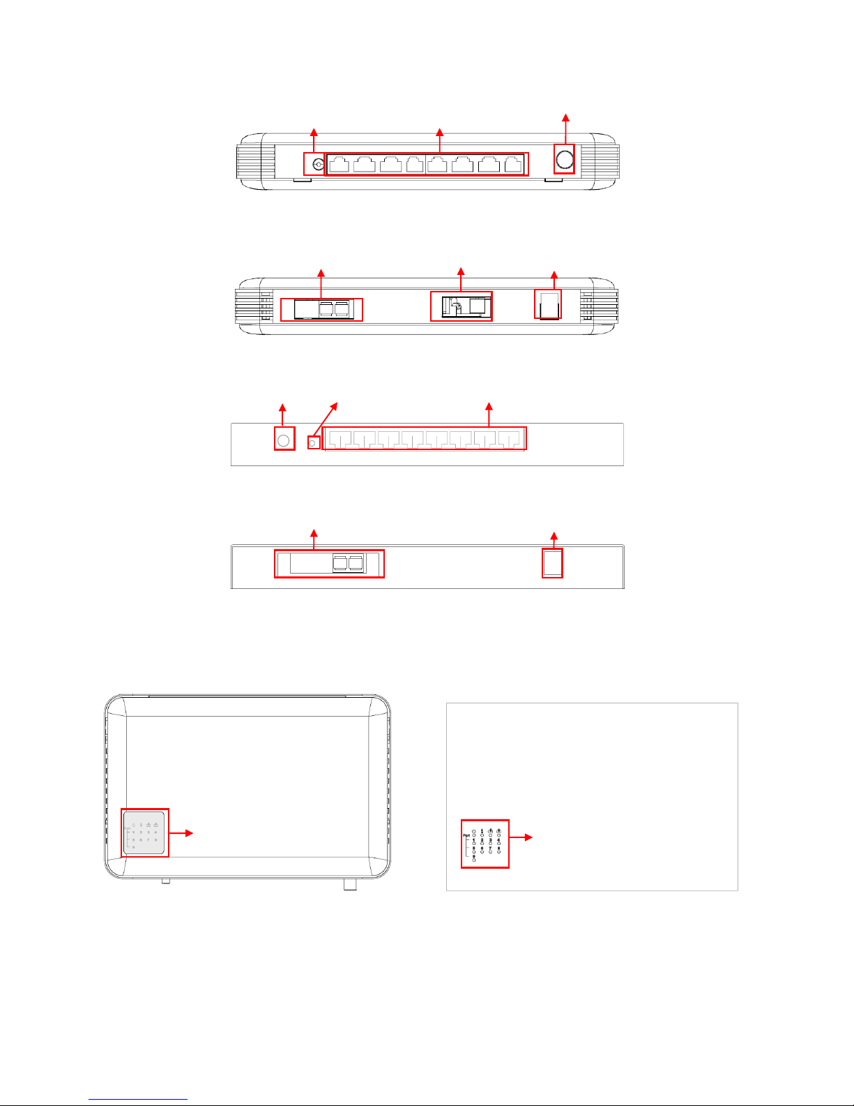
Figure 3. Front Panel for 9-Port 10/100/1000Base-T Ethernet Managed Switch (metal housing)
Figure 4. Rear Panel for 9-Port 10/100/1000Base-T Ethernet Managed Switch (metal housing)
Smart Lighting Control
10/100/1000Mbps RJ-45 ports
10/100/1000Mbps RJ-45 ports
Smart Lighting Control
Grounding Wire
7
Figure 5. Front Panel for 8-Port 10/100/1000Base-T plus 1-Port 1000Base-X or 100/1000Base-X Uplink
Ethernet Managed Switch with CATV RF Module (plastic housing)
Figure 6. Rear Panel for 8-Port 10/100/1000Base-T plus 1-Port 1000Base-X or 100/1000Base-X Uplink
Ethernet Managed Switch with CATV RF & Battery Charging Module (plastic housing)
Figure 7. Front Panel for 8-Port 10/100/1000Base-T plus 1-Port 1000Base-X or 100/1000Base-X Uplink
Ethernet Managed Switch (metal housing)
Figure 8. Rear Panel for 8-Port 10/100/1000Base-T plus 1-Port 1000Base-X or 100/1000Base-X Uplink
Ethernet Managed Switch with Battery Charging Module (metal housing)
All models have the same top, left and right panel.
Figure 9. Top Panel with LEDs (plastic housing) Figure 10. Top Panel with LEDs (metal housing)
10/100/1000Mbps RJ-45 ports
CATV RF (Optional)
1000Mbps F/O port
LED Indicators
CATV RF Input (Optional)
Battery Charging (Optional)
Smart Lighting Control
LED Indicators
10/100/1000Mbps RJ-45 ports
Smart Lighting Control
Grounding Wire
1000Mbps F/O port
Battery Charging (Optional)
8
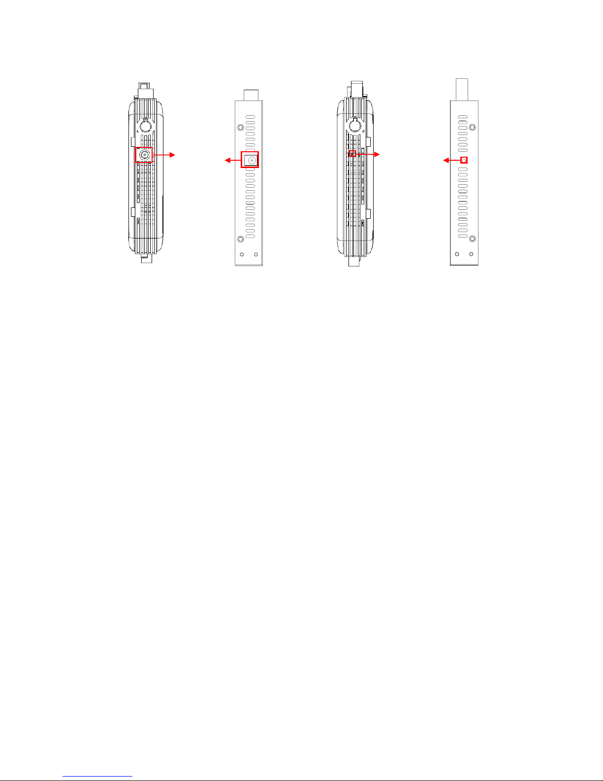
(Plastic housing) (Metal housing) (Plastic housing) (Metal housing)
Figure 11. Left Panel Figure 12. Right Panel
1.2 Management Preparations
The Managed Switch can be accessed through both Telnet connection and a web browser,
such as Internet Explorer or Netscape, etc.. Before you can access the Managed Switch to
configure it, you need to connect cables properly.
1.2.1 Connecting the Managed Switch
It is extremely important that proper cables are used with correct pin arrangements when
connecting Managed Switch to other devices such as switches, hubs, workstations, etc..
1000Base-X Fiber Port or 100/1000 Base-X Fiber Port
The 1000Base-X fiber port is located at the rear panel of the Managed Switch. This
port is primarily used for uplink connection and can operate at 1000M/Full or Half
Duplex mode. Duplex SC or WDM Simplex SC types of connectors are available. Use
proper multimode or single-mode optical fiber cable to connect this port with the other
Ethernet Fiber port.
Before connecting to other switches, workstations or media converters, make sure
both sides of the fiber transfer are with the same media type, for example 1000Base-X
Single-mode to 1000Base-X Single-mode, 1000Base-X Multimode to 1000Base-X
Multimode. Check that the fiber-optic cable type matches the fiber transfer model. To
connect to 1000Base-SX transfer, use the multimode fiber cable (one side must be
male duplex SC connector type). To connect to 1000Base-LX transfer, use the singlemode fiber cable (one side must be male duplex LC connector type).
Power Jack
Connector
Reset Button

9
10/100/1000Base-T RJ-45 Ports
Depending on the model that you purchased, 8 or 9 10/100/1000Base-T RJ-45 ports
are located on the front panel of the Managed Switch. These RJ-45 ports allow users
to connect their traditional copper-based Ethernet devices to network. All these ports
support auto-negotiation and MDI/MDIX auto-crossover, i.e. the crossover or straight
through CAT-5 cable may be used.
1.2.2 Assigning IP Addresses
IP addresses have the format n.n.n.n, for example 168.168.8.100.
IP addresses are made up of two parts:
The first part (168.168.XXX.XXX in the example) indicates network address identifying
the network where the device resides. Network addresses are assigned by three
allocation organizations. Depending on your location, each allocation organization
assigns a globally unique network number to each network that wishes to connect to
the Internet.
The second part (XXX.XXX.8.100 in the example) identifies the device within the
network. Assigning unique device numbers is your responsibility. If you are unsure of
the IP addresses allocated to you, consult the allocation organization from which your
IP addresses were obtained.
Remember that an address can be assigned to only one device on a network. If you connect
to the outside, you must change all the arbitrary IP addresses to comply with those you have
been allocated by the allocation organization. If you do not do this, your outside
communications will not be connected.
A subnet mask is a filtering system for IP addresses. It allows you to further subdivide your
network. You must use the proper subnet mask for a proper operation of a network with
subnets defined.
10
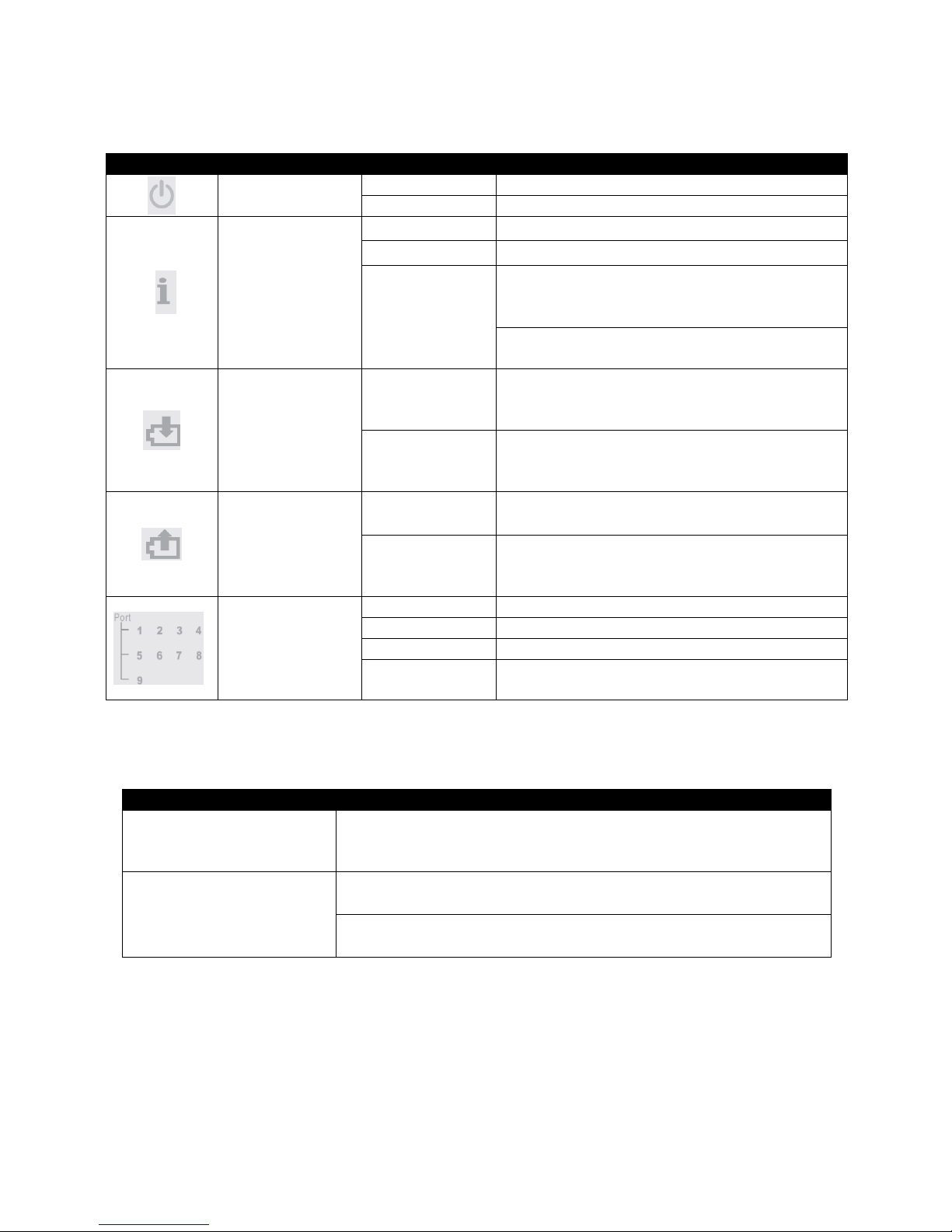
1.3 LED Definitions
LED
Definition
Color
Operation
Power
Off
Device is powered off.
Green
Device is powered on.
System Status
Orange
System is booting up.
Green
System is working normally.
Orange
Blinking
When the system is set back to default
factory setting, the Status LED indicator
will blink in orange for 3 times.
When the system is restarted, the Status
LED indicator will blink in orange once.
Battery
Charging
(For BAT
models only)
Green
When the battery is connected to the
device, steady green indicates that it is
fully charged.
Green Blinking
When the battery is connected to the
device, green blinking indicates that it is
charging.
Battery
Discharging
(For BAT
models only)
Orange
The battery is installed or connected
incorrectly.
Orange
Blinking
When battery is installed to the device,
orange blinking indicates that the battery is
in use.
Port Link Status
Off
Port link is down
Green
Link is up and works under 10/100Mbps.
Orange
Link is up and works under 1000Mbps.
Green/Orange
Blinking
The port is receiving and transmitting data.
1.4 Button Definitions
Button
Operation
Smart Lighting Control
Button
System Status LED and Port Link LEDs will be turned off by
pressing the button. Only Power and Battery Discharging
LED indicators stay on.
Reset Button
Insert a pin or paper clip to press the Reset button for 5
seconds to restart the device.
Insert a pin or paper clip to press the Reset button for 10
seconds to reset the device to factory defaults.

11
2. Command Line Interface (CLI)
This chapter guides you to use Command Line Interface (CLI) via Telnet connection,
specifically in:
Configuring the system
Resetting the system
Upgrading newly released firmware
2.1 Remote Console Management-Telnet
You can use Command Line Interface to manage the Managed Switch via Telnet session.
For first-time users, you must first assign a unique IP address to the Managed Switch before
you can manage it remotely. Use any one of the RJ-45 ports on the front panel as the
temporary management console port to login to the device with the default username &
password and then assign the IP address using IP command in Global Configuration mode.
Follow steps described below to access the Managed Switch through Telnet session:
Step 1. Use any one of the RJ-45 ports on the front panel as a temporary management
console port to login to the Managed Switch.
Step 2. Run Telnet client and connect to 192.168.0.1. For first-time users, make sure
the IP address of your PC or workstation is assigned to an IP address between
192.168.0.2 and 192.168.0.254 with subnet mask 255.255.255.0.
Step 3. When asked for a username, enter “admin”. When asked for a password, leave
the password field blank and press Enter (by default, no password is required.)
Step 4. If you enter CLI successfully, the prompt display Switch> (the model name of
your device together with a greater than sign) will appear on the screen.
Step 5. Once you enter CLI successfully, you can set up the Switch‟s IP address,
subnet mask and the default gateway using “IP” command in Global
Configuration mode. The telnet session will be terminated immediately once the
IP address of the Switch has been changed.
Step 6. Use new IP address to login to the Managed Switch via Telnet session again.
Limitation: Only one active Telnet session can access the Managed Switch at a time.

12
2.2 Navigating CLI
After you successfully access to the Managed Switch, you will be asked for a login username.
Enter your authorized username and password, and then you will be directed to the User
Mode. In CLI management, the User Mode only provides users with basic functions to
operate the Managed Switch. If you would like to configure advanced features of the
Managed Switch, such as, VLAN, QoS, and Rate limit control, you must enter the
Configuration Mode. The following table provides an overview of modes available in this
Managed Switch.
Command Mode
Access Method
Prompt Displayed
Exit Method
User Mode
Login username &
password
Switch>
logout
Privileged Mode
From user mode, enter
the enable command
Switch#
disable, exit, logout
Configuration
Mode
From the enable mode,
enter the config or
configure command
Switch(config)#
exit
NOTE: By default, the model name will be used for the prompt display. You can change
the prompt display to the one that is ideal for your network environment using the “hostname” command. However, for convenience, the prompt display “Switch” will be used
throughout this user’s manual.
2.2.1 General Commands
This section introduces you some general commands that you can use in all modes, including
“help”, “exit”, “history” and “logout”.
Entering the command…
To do this…
Available Modes
help
Obtain a list of available
commands in the current mode.
User Mode
Privileged Mode
Configuration Mode
exit
Return to the previous mode or
login screen.
User Mode
Privileged Mode
Configuration Mode
history
List all commands that have been
used.
User Mode
Privileged Mode
Configuration Mode
logout
Logout from the CLI or terminate
Telnet session.
User Mode
Privileged Mode

13
2.2.2 Quick Keys
In CLI, there are several quick keys that you can use to perform several functions. The
following table summarizes the most frequently used quick keys in CLI.
Keys
Purpose
tab
Enter an unfinished command and press “Tab” key to complete the
command.
?
Press “?” key in each mode to get available commands.
Unfinished
command
followed by ?
Enter an unfinished command or keyword and press “?” key to complete
the command and get command syntax help.
Examples:
Switch#h?
help Show available commands
history Show history commands
Switch#he?
<cr>
Switch#help
Up arrow
Use Up arrow key to scroll through the previous entered commands,
beginning with the most recent key-in commands.
Down arrow
Use Down arrow key to scroll through the previous entered commands,
beginning with the commands that are entered first.
2.2.3 Command Format
While in CLI, you will see several symbols very often. As mentioned above, you might already
know what “>”, “#” and (config)# represent. However, to perform what you intend the device to
do, you have to enter a string of complete command correctly. For example, if you want to
assign IP address for the Managed Switch, you need to enter the following command with the
required parameter and IP, subnet mask and default gateway:
IP command syntax: Switch(config)#ip address [A.B.C.D] [255.X.X.X] [A.B.C.D]
Switch(config)#ip address 192.168.1.198 255.255.255.255 192.168.1.254
This means that
you are in Global
Configuration mode
This allows you to
assign IP address.
Enter the IP address, subnet mask, and
default gateway address.
Hostname

14
The following table lists common symbols and syntax that you will see very frequently in this
User‟s Manual for your reference:
Symbols
Brief Description
>
Currently, the device is in User Mode.
#
Currently, the device is in Privileged Mode.
(config)#
Currently, the device is in Global
Configuration Mode.
Syntax
Brief Description
[ ]
Brackets mean that this field is required
information.
[A.B.C.D ]
Brackets represent that this is a required
field. Enter an IP address or gateway
address.
[255.X.X.X]
Brackets represent that this is a required
field. Enter the subnet mask.
[port-based | 802.1p | dscp | vid]
There are four options that you can choose.
Specify one of them.
[1-8191]
Specify a value between 1 and 8191.
[0-7] 802.1p_list
[0-63] dscp_list
Specify one or more values or a range of
values.
For example: specifying one value
Switch(config)#qos 802.1p-map 1 0
Switch(config)#qos dscp-map 10 3
For example: specifying three values
(separated by commas)
Switch(config)#qos 802.1p-map 1,3 0
Switch(config)#qos dscp-map 10,13,15 3
For example: specifying a range of values
(separating by a hyphen)
Switch(config)#qos 802.1p-map 1-3 0
Switch(config)#qos dscp-map 10-15 3

15
2.2.4 Login Username & Password
Default Login
After you enter Telnet session, a login prompt will appear to request a valid and authorized
username and password combination. For first-time users, enter the default login username
“admin” and “press Enter key” in password field (no password is required for default setting).
When system prompt shows “Switch>”, it means that the user has successfully entered the
User Mode.
For security reasons, it is strongly recommended that you add a new login username and
password using User command in Configuration Mode. When you create your own login
username and password, you can delete the default username (admin) to prevent
unauthorized accesses.
Forgot Your Login Username & Password?
If you forgot your login username and password, you can use the “reset button” to set all
configurations back to factory defaults. Once you have performed system reset to defaults,
you can login with default username and password. Please note that if you use this method to
gain access to the Managed Switch, all configurations saved in Flash will be lost. It is strongly
recommended that a copy of configurations is backed up in your local hard-drive or file server
from time to time so that previously-configured settings can be restored to the Managed
Switch for use after you gain access again to the device.
2.3 User Mode
In User mode, only a limited set of commands are provided. Please note that in Use Mode,
you have no authority to configure advanced settings. You need to enter Privileged mode and
Configuration mode to set up advanced functions of a switch feature. For a list of commands
available in User Mode, enter the question mark (?) or “help” command after the system
prompt displays “Switch>”.
Command
Description
exit
Quit the User mode or close the terminal connection.
help
Display a list of available commands in User mode.
history
Display the command history.
logout
Logout from the Managed Switch.
enable
Enter the Privileged mode.

16
2.4 Privileged Mode
The only place where you can enter the Privileged (Enable) Mode is in User Mode. When you
successfully enter Enable mode, the prompt will be changed to Switch# (the model name of
your device together with a pound sign). Enter the question mark (?) or help command to
view a list of commands available for use.
Command
Description
copy-cfg
Restore or backup configuration file via FTP or TFTP server.
configure
Enter Global Configuration mode.
disable
Exit Enable Mode and return to User Mode.
exit
Exit Enable Mode and return to User Mode.
firmware
Upgrade Firmware via FTP or TFTP server.
help
Display a list of available commands in Enable Mode.
history
Show commands that have been used.
logout
Logout from the Managed Switch.
reload
Restart the Managed Switch.
write
Save your configurations to Flash.
show
Show a list of commands or show the current setting of each listed command.
2.4.1 Copy-cfg Command
Use “copy-cfg” command to backup a configuration file via FTP or TFTP server or restore the
Managed Switch back to the defaults or to the defaults without changing IP configurations.
1. Restore a configuration file via FTP or TFTP server.
Command
Parameter
Description
Switch# copy-cfg
from ftp [A.B.C.D]
[file name]
[user_name]
[password]
[A.B.C.D]
Enter the IP address of your FTP server.
[file_name]
Enter the configuration file name that you
want to restore.
[user_name]
Enter the username for FTP server login.
[password]
Enter the password for FTP server login.
Switch# copy-cfg
from tftp [A.B.C.D]
[file_name]
[A.B.C.D]
Enter the IP address of your TFTP server.
[file_name]
Enter the configuration file name that you
want to restore.
Example
Switch# copy-cfg from ftp 192.168.1.198 HS_0600_file.conf misadmin1 abcxyz
Switch# copy-cfg from tftp 192.168.1.198 HS_0600_file.conf
2. Restore the Managed Switch back to default settings.
Command / Example
Switch# copy-cfg from default
NOTE: There are two ways to set the Managed Switch back to the factory default settings.
Users can use the “copy-cfg from default” command in CLI or simply press the “Reset Button”
located on the front panel to restore the device back to the initial state.

17
3. Restore the Managed Switch back to default settings but keep IP configurations.
Command / Example
Switch# copy-cfg from default keep-ip
4. Backup a configuration file to TFTP server.
Command
Parameter
Description
Switch# copy-cfg to
ftp [A.B.C.D]
[file_name]
[user_name]
[password]
[A.B.C.D]
Enter the IP address of your FTP server.
[file_name]
Enter the configuration file name that you want to
backup.
[user_name]
Enter the username for FTP server login.
[password]
Enter the password for FTP server login.
Switch# copy-cfg to
tftp [A.B.C.D]
[file_name]
[A.B.C.D]
Enter the IP address of your TFTP server.
[file_name]
Enter the configuration file name that you want to
backup.
Example
Switch# copy-cfg to ftp 192.168.1.198 HS_0600_file.conf misadmin1 abcxyz
Switch# copy-cfg to tftp 192.168.1.198 HS_0600_file.conf
2.4.2 Firmware Command
To upgrade Firmware via FTP or TFTP server.
Command
Parameter
Description
Switch# firmware
upgrade ftp
[A.B.C.D]
[file_name]
[user_name]
[password]
[A.B.C.D]
Enter the IP address of your FTP server.
[file_name]
Enter the firmware file name that you want to upgrade.
[user_name]
Enter the username for FTP server login.
[password]
Enter the password for FTP server login.
Switch# firmware
upgrade tftp
[A.B.C.D]
[file_name]
[A.B.C.D]
Enter the IP address of your TFTP server.
[file_name]
Enter the firmware file name that you want to upgrade.
Example
Switch# firmware upgrade ftp 192.168.1.198 HS_0600_file.bin edgeswitch10 abcxyz
Switch# firmware upgrade tftp 192.168.1.198 HS_0600_file.bin
2.4.3 Reload Command
To restart the Managed Switch, enter the reload command.
Command / Example
Switch# reload

18
2.4.4 Write Command
To save running configurations to startup configurations, enter the write command. All
unsaved configurations will be lost when you restart the Managed Switch.
Command / Example
Switch# write
2.4.5 Configure Command
The only place where you can enter Global Configuration Mode is in Privileged Mode. You
can type in “configure” or “config” for short to enter Global Configuration Mode. The display
prompt will change from “Switch#” to “Switch(config)#” once you successfully enter Global
Configuration Mode.
Command / Example
Switch# config
Switch(config)#
Switch# configure
Switch(config)#
2.5 Configuration Mode
When you enter “configure” or “config” and press “Enter” in Privileged Mode, you will be
directed to Global Configuration Mode where you can set up advanced switching functions,
such as QoS, VLAN, and storm control security globally. Any command entered will be
applied to running-configuration and the device‟s operation. From this level, you can also
enter different sub-configuration modes to set up specific configurations for VLAN, QoS,
security or interfaces.
Command
Description
catv
Enable or disable CATV RF module
exit
Exit the Configuration Mode.
help
Display a list of available commands in Configuration Mode.
history
Show commands that have been used.
ip
Set up the IP address and enable DHCP mode & IGMP snooping.
loop-detection
Enable or disable Loop Detection function
mac
Set up each port‟s MAC learning function.
management
Set up the system service type.
ntp
Set up required configurations for Network Time Protocol.
qos
Set up the priority of packets within the Managed Switch.
snmp-server
Create a new SNMP community and trap destination and specify the trap types.
switch
Enable or disable SFP and counter polling function.
switch-info
Specify company name, host name, system location, etc..
user
Create a new user account.
vlan
Set up VLAN mode and VLAN configuration.
no
Disable a command or set it back to its default setting.
interface
Set up the selected interfaces‟ advanced features.
show
Show a list of commands or show the current setting of each listed command.

19
2.5.1 Entering Interface Numbers
In the Global Configuration Mode, you can configure a command that is only applied to
interfaces specified. For example, you can set up each interface‟s VLAN assignment, speed,
or duplex mode. To configure, you must first enter the interface number. There are four ways
to enter your interface numbers to signify the combination of different interfaces that apply to
a command or commands.
Commands
Description
Switch(config)# interface 1
Switch(config-if-1)#
Enter a single interface. Only interface 1 will apply to
commands entered.
Switch(config)# interface 1,3,5
Switch(config-if-1,3,5)#
Enter three discontinuous interfaces, separating by a
comma. Interface 1, 3, 5 will apply to commands
entered.
Switch(config)# interface 1-3
Switch(config-if-1-3)#
Enter three continuous interfaces. Use a hyphen to
signify a range of interface numbers. In this example,
interface 1, 2, and 3 will apply to commands entered.
Switch(config)# interface 1,3-5
Switch(config-if-1,3-5)#
Enter a single interface number together with a range
of interface numbers. Use both commas and hyphens
o signify the combination of different interface
numbers. In this example, interface 1, 3, 4, 5 will apply
to commands entered.
The “interface” command can be used together with “Loop Detection”, “QoS”, “VLAN” and
“Security” commands. For detailed usages, please refer to Loop Detection, QoS, VLAN and
Security sections below.
2.5.2 No Command
Most commands that you enter in Configuration mode can be negated using “no” command
followed by the same or original command. The purpose of “no” command is to disable a
function, remove a command, or set the setting back to the default value. In each sub-section
below, the use of no command to fulfill different purposes will be introduced.
2.5.3 Show Command
The command “show” is very important for network administrators to get information about
the device, receive outputs to verify a command‟s configurations or troubleshoot a network
configuration error. “Show” command can be used in Privileged or Configuration mode. The
following describes different uses of “show” command.
20
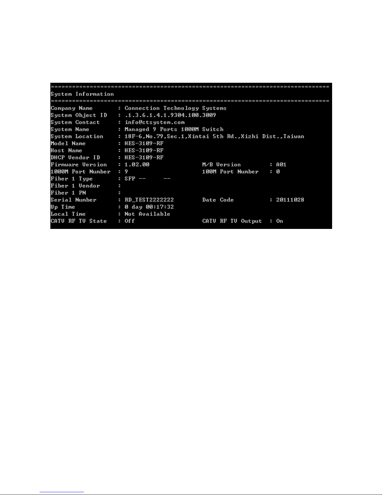
1. Display system information
Enter “show switch-info” command in Privileged or Configuration mode, and then the
following similar screen page will appear.
Company Name: Display a company name for this Managed Switch. Use “switch-info
company-name [company-name]” command to edit this field.
System Object ID: Display the predefined System OID.
System Contact: Display contact information for this Managed Switch. Use “switch-info sys-
contact [sys-contact]” command to edit this field.
System Name: Display a descriptive system name for this Managed Switch. Use “switch-info
sys-name [sys-name]” command to edit this field.
System Location: Display a brief location description for this Managed Switch. Use “switch-
info sys-location [sys-location]” command to edit this field.
Model Name: Display the product‟s model name.
Host Name: Display the product‟s host name.
DHCP Vendor ID: Display the product‟s DHCP Vendor ID.
Firmware Version: Display the firmware version used in this device.
M/B Version: Display the main board version.
1000M Port Number: The number of ports transmitting at the speed of 1000Mbps

21
100M Port Number: The number of ports transmitting at the speed of 100Mbps
Fiber 1 Type: Display the information about the slide-in or fixed fiber type.
Fiber 1 Vendor: Display the vendor of the slide-in or fixed fiber.
Fiber 1 PN: Displays the PN of the slide-in or fixed fiber.
Serial Number: Display the serial number of this Managed Switch.
Date Code: Displays the Managed Switch Firmware date code.
Uptime: Display the time the device has been up.
Local Time: Display the time of the location where the switch is.
CATV RF TV State: View-only field that shows whether RF TV is ready or not.
CATV RF TV Output: Turn on or off the RF TV Output.
2. Display or verify currently-configured settings
Refer to “interface command”, “ip command”, “mac command”, “qos command”, “security
command”, “snmp-server command”, “user command”, and “vlan command” sections.
3. Display interface information or statistics
Refer to “show interface statistics command” and “show sfp information command” sections.
4. Show running and startup configurations
Refer to “show running-config command” and “show start-up-config command” sections.
2.5.4 Interface Command
Use this command to set up various port configurations of discontinuous or a range of ports.
Command
Parameter
Description
Switch(config)# interface
[port_list]
[port_list]
Enter several port numbers separated by
commas or a range of port numbers.
For example: 1,3 or 2-4
Switch(config-if-PORT-PORT)#
auto-negotiation
Set the selected interfaces‟ to autonegotiation. When auto-negotiation is
enabled, speed configuration will be
ignored.

22
Switch(config-if-PORT-PORT)#
duplex full
Set the selected interfaces‟ to full duplex
mode.
Switch(config-if-PORT-PORT)#
flowcontrol
Enable the selected interfaces‟ flow
control function.
Switch(config-if-PORT-PORT)#
speed [1000 |100 | 10]
[1000 |100 |
10]
Set up the selected interfaces‟ speed.
Speed configuration only works when “no
auto-negotiation” command is issued.
Switch(config-if-PORT-PORT)#
description [description]
[description]
Specify a descriptive name for the
selected interfaces.
Switch(config-if-PORT-PORT)#
shutdown
Administratively disable the selected
ports‟ status.
No command
Switch(config-if-PORT-PORT)# no autonegotiation
Set auto-negotiation setting to the default
setting.
Switch(config-if-PORT-PORT)# no duplex
Set the selected ports‟ duplex mode to the
default setting.
Switch(config-if-PORT-PORT)# no speed
Set the selected ports‟ speed to the
default setting.
Switch(config-if-PORT-PORT)# no flowcontrol
Set the selected ports‟ flow control
function to the default setting.
Switch(config-if-PORT-PORT)# no description
Remove the entered description name for
the selected ports.
Switch(config-if-PORT-PORT)# no shutdown
Administratively enable the selected ports‟
status.
Show command
Switch(config)# show interface status
Show each interface‟s port status
including media type, forwarding state,
speed, duplex mode, flow control and link
up/down status.
Interface command example
Switch(config)# interface 1-3
Enter port 1 to port 3‟s interface mode.
Switch(config-if-1-3)# auto-negotiation
Set the selected interfaces‟ to autonegotiation.
Switch(config-if-1-3)# duplex full
Set the selected interfaces‟ to full duplex
mode.
Switch(config-if-1-3)# speed 100
Set the selected ports‟ speed to 100Mbps.
Switch(config-if-1-3)# shutdown
Administratively disable the selected
ports‟ status.

23
2.5.5 CATV Command
Enable or disable CATV RF module.
CATV command
Description
Switch(config)# catv
Enable CATV RF module.
No command
Switch(config)# no catv
Disable CATV RF module.
Show command
Switch(config)# show switch-info
Show current CATV RF module status.
2.5.6 IP Command
Configure IP address and related settings such as DHCP snooping and IGMP snooping.
1. Set up or remove the IP address of the Managed Switch.
IP command
Parameter
Description
Switch(config)#
ip address
[A.B.C.D]
[255.X.X.X]
[A.B.C.D]
[A.B.C.D]
Enter the desired IP address for the Managed Switch.
[255.X.X.X]
Enter subnet mask of your IP address.
[A.B.C.D]
Enter the default gateway address.
Switch(config)#
ip dhcp snooping
Enable DHCP Snooping function
Switch(config)#
ip dhcp snooping
dhcp-server
[port_list]
[port_list]
Specify DHCP server trust ports.
No command
Switch(config)# no ip address
Remove the Switch‟s IP address.
Show command
Switch(config)# show ip address
Show the current IP configurations or verify the
configured IP settings.
IP command example
Switch(config)# ip address
192.168.1.198 255.255.255.0
192.168.1.254
Set up the Switch‟s IP to 192.168.1.198, subnet mask
to 255.255.255.0, and default gateway to
192.168.1.254.

24
2. Enable the Managed Switch to automatically get IP address from the DHCP server.
Command / Example
Description
Switch(config)# ip address dhcp
Enable DHCP mode.
No command
Switch(config)# no ip address dhcp
Disable DHCP mode.
Show command
Switch(config)# show ip address
Show the current IP configurations or verify
the configured IP settings.
3. Enable or disable DHCP snooping globally.
Command / Example
Parameter
Description
Switch(config)# ip dhcp
snooping
Enable DHCP snooping function.
Switch(config)# ip dhcp
snooping dhcp-server [port_list]
[port_list]
Specify DHCP server trust ports.
No command
Switch(config)# no ip dhcp snooping
Disable IGMP snooping function.
Switch(config)# no ip dhcp snooping dhcp-server
Remove all the DHCP server trust
ports
Show command
Switch(config)# show ip dhcp snooping
Show current DHCP snooping status
including DHCP server trust ports.
4. Enable or disable IGMP snooping globally.
IGMP, Internet Group Management Protocol, is a communications protocol used to manage
the membership of Internet Protocol multicast groups. IGMP is used by IP hosts and adjacent
multicast routers to establish multicast group memberships. It can be used for online
streaming video and gaming, and allows more efficient use of resources when supporting
these uses.
IGMP Snooping is the process of listening to IGMP traffic. IGMP snooping, as implied by the
name, is a feature that allows the switch to “listen in” on the IGMP conversation between
hosts and routers by processing the layer 3 packets IGMP packets sent in a multicast
network.
When IGMP snooping is enabled in a switch, it analyses all the IGMP packets between hosts
connected to the switch and multicast routers in the network. When a switch hears an IGMP
report from a host for a given multicast group, the switch adds the host‟s port number to the
multicast list for that group. And, when the switch hears an IGMP Leave, it removes the host‟s
port from the table entry.
IGMP snooping can very effectively reduce multicast traffic from streaming and other
bandwidth intensive IP applications. A switch using IGMP snooping will only forward multicast
traffic to the hosts interested in that traffic. This reduction of multicast traffic reduces the
packet processing at the switch (at the cost of needing additional memory to handle the

25
multicast tables) and also reduces the workload at the end hosts since their network cards (or
operating system) will not have to receive and filter all the multicast traffic generated in the
network.
Command / Example
Parameter
Description
Switch(config)# ip igmp
snooping
Enable IGMP snooping function.
Switch(config)# ip igmp
snooping aging-time
[1-6000] /10 sec.
Specify the IGMP querier aging time.
If the switch does not receive join
packets from the end device within the
specified time, the entry associated
with this end device will be removed
from the IGMP table.
No command
Switch(config)# no ip igmp snooping
Disable IGMP snooping function.
Switch(config)# no ip igmp snooping aging time
Remove IGMP querier aging time
setting.
Show command
Switch(config)# show ip igmp snooping
Show current IGMP snooping status
including immediate leave function.
Switch(config)# show ip igmp snooping groups
Show IGMP group table. When IGMP
Snooping is enabled, the Switch is
able to read multicast group IP and
the corresponding MAC address from
IGMP packets that enter the device.
5. Enable or disable IGMP snooping immediate-leave function.
This works only when IGMP Snooping is enabled. When Immediate Leave is enabled, the
Switch immediately removes the port when it detects IGMPv1 & IGMPv2 leave message on
that port.
Command / Example
Description
Switch(config)# ip igmp snooping
immediate-leave
Enable IGMP immediate leave function.
No command
Switch(config)# no ip igmp snooping
immediate-leave
Disable IGMP immediate leave function.
Show command
Switch(config)# show ip igmp snooping
Show current IGMP snooping status
including immediate leave function.
Switch(config)# show ip igmp snooping
groups
Show IGMP group table.

26
2.5.7 Loop Detection Command
Enable or disable Loop Detection function.
Loop Detection allows users to configure the Managed Switch to lock a port when it detects
packets that sent out on that port loop back to the switch. When loops occur, it will cause
broadcast storm and affect the performance of layer two Access switch. To avoid this, Loop
Detection can be enabled on LAN port of the Managed Switch. When it detects the loop, it
will lock the port which receives the loop packet immediately and send out SNMP trap to
inform the network administrator.
Loop Detection command
Parameter
Description
Switch(config)# loop-detection
Globally enable Loop Detection
function. By default, this function is
disabled.
Switch(config)# interface
[port_list]
[port_list]
Enter several port numbers separated
by commas or a range of port
numbers.
For example: 1,3 or 2-4
Switch(config-if-PORT-PORT)#
loop-detection
Enable Loop Detection function on the
selected physical ports.
No command
Switch(config)# no loop-detection
Globally disable Loop Detection
function.
Switch(config-if-PORT-PORT)# no loop-detection
Disable Loop Detection function on
the selected physical ports.
Show command
Switch(config)# show loop-detection
Show current Loop Detection
configuration information.
Switch(config)# show loop-detection status
Show information concerning locked
ports and locked cause.
Note: Please note that Loop Detection function is only available on LAN 1~8 port.
2.5.8 MAC Command
Set up MAC address table aging time. Entries in the MAC address table containing source
MAC addresses and their associated ports will be deleted if they are not accessed within the
specified aging time.
MAC Command
Parameter
Description
Switch(config)# mac addresstable aging-time [1-800]
[1-800]
Enter aging time for MAC address table.
Numbers available are from 1 to 800.
No command
Switch(config)# no mac address-table agingtime
Set MAC address table aging time to the
default value (300 seconds).

27
Show command
Switch(config)# show mac agingtime
Show current MAC address table aging
time or verify currently configured aging
time.
Switch(config)# show mac
address-table
Show MAC addresses learned by the
Managed Switch
Switch(config)# show mac
address-table interface [port_list]
[port_list]
Show MAC addresses learned by the
selected ports.
Switch(config)# show mac
address-table mac [mac_addr]
[mac_addr]
Show the specified MAC address
information including the MAC learning
type (Static or Dynamic) and MAC learning
port.
MAC command example
Switch(config)# mac address-table aging-time
600
Set MAC address table aging time to 600
seconds.
2.5.9 Management Command
Management command
Parameter
Description
Switch(config)# management
[ssh | telnet]
[ssh | telnet]
Select the system service type, SSH or
telnet.
No command
Switch(config)# no management
[ssh | telnet]
[ssh | telnet]
Set system service type to Disabled.
Show command
Switch(config)# show management
Show the current system service type.
Management command example
Switch(config)# management ssh
Enable SSH system service type.
2.5.10 NTP Command
Set up required configurations for Network Time Protocol.
Command
Parameter
Description
Switch(config)# ntp
Enable the Managed Switch to
synchronize the clock with a time server.
Switch(config)# ntp server1
[A.B.C.D]
[A.B.C.D]
Specify the primary time server IP
address.
Switch(config)# ntp server2
[A.B.C.D]
[A.B.C.D]
Specify the secondary time server IP
address.
Switch(config)# ntp syn-interval
[1-99999]
[1-99999]
Specify the interval time to synchronize
from NTP time server. The allowable
value is between 1 and 99999 minutes.

28
Switch(config)# ntp time-zone [0132]
[0-132]
Specify the time zone to that the Managed
Switch belongs. Use any key to view the
complete code list of 132 time zones. For
example, “Switch(config)# ntp timezone ?”
No command
Switch(config)# no ntp
Disable the Managed Switch to
synchronize the clock with a time server.
Switch(config)# no ntp server1
Delete the primary time server IP address.
Switch(config)# no ntp server2
Delete the secondary time server IP
address.
Switch(config)# no ntp syn-interval
Set the synchronization interval back to
the default setting.
Switch(config)# no ntp time-zone
Set the time-zone setting back to the
default setting.
Show command
Switch(config)# show ntp
Show or verify current time server settings.
NTP command example
Switch(config)# ntp
Enable the Managed Switch to
synchronize the clock with a time server.
Switch(config)# ntp server1 192.180.0.12
Set the primary time server IP address to
192.180.0.12.
Switch(config)# ntp server2 192.180.0.13
Set the secondary time server IP address
to 192.180.0.13.
Switch(config)# ntp syn-interval 6000
Set the synchronization interval to 6000
minutes.
Switch(config)# ntp time-zone 4
Set the time zone to GMT-8:00 Vancouver.
2.5.11 QoS Command
1. Specify the desired QoS mode.
QoS command
Parameter
Description
Switch(config)# qos [portbased | 802.1p | dscp | vid]
[port-based |
802.1p | dscp |
vid]
Specify one QoS mode.
port-based: Use “interface” and “qos
default-class” command to assign a queue
to the selected interfaces.
802.1p: Use “qos 802.1p_map” command
to assign priority bits to a queue.
dscp: Use “qos dscp-map [0-63] dscp_list
[0-3]” to assign several DSCP values to a
priority value.
vid: Use vid-map command to assign the
specific VIDs to the specific queue.
 Loading...