


1
HES-3109 SERIES
9 PORTS 10/100/1000BASE-T MANAGEMENT ETHERNET
SWITCH
8 PORTS 10/100/1000BASE-T MANAGEMENT ETHERNET
SWITCH WITH 1 PORT 1000BASE-X UPLINK OR 1 PORT
100/1000BASE-X UPLINK
8 PORTS 10/100/1000BASE-T MANAGEMENT ETHERNET
SWITCH WITH 1 PORT 1000BASE-X UPLINK OR 1 PORT
100/1000BASE-X UPLINK AND TV RF RECEIVER
8 PORTS 10/100/1000BASE-T MANAGEMENT ETHERNET
SWITCH WITH 1 PORT 1000BASE-X UPLINK OR 1 PORT
100/1000BASE-X UPLINK WITH BATTERY CHARGING
FUNCTION
8 PORTS 10/100/1000BASE-T MANAGEMENT ETHERNET
SWITCH WITH 1 PORT 1000BASE-X UPLINK OR 1 PORT
100/1000BASE-X UPLINK WITH BATTERY CHARGING
FUNCTION AND TV RF RECEIVER
Network Management
User’s Manual
Version 0.91

2
Trademarks
CTS is a registered trademark of Connection Technology Systems Inc.
Contents subject to revise without prior notice.
All other trademarks remain the property of their owners.
Copyright Statement
Copyright Connection Technology Systems Inc.
This publication may not be reproduced as a whole or in part, in any way whatsoever unless prior consent has been
obtained from Connection Technology Systems Inc.
FCC Warning
This equipment has been tested and found to comply with the limits for a Class A digital device, pursuant to Part 15 of the
FCC Rules. These limitations are designed to provide reasonable protection against harmful interference in a residential
installation. This equipment generates uses and can radiate radio frequency energy and, if no installed and used in
accordance with the instructions, may cause harmful interference to radio communications. However, there is no
guarantee that interference will not occur in a particular installation. If this equipment does cause harmful interference to
radio or television reception, which can be determined by turning the equipment off and on, the user is encouraged to try to
correct the interference by one or more of the following measures:
Reorient or relocate the receiving antenna.
Increase the separation between the equipment and receiver.
Connect the equipment into a different outlet from that the receiver is connected.
Consult your local distributors or an experienced radio/TV technician for help.
Shielded interface cables must be used in order to comply with emission limits.
Changes or modifications to the equipment, which are not approved by the party responsible for compliance, could affect
the user’s authority to operate the equipment.
Copyright © 2011 All Rights Reserved.
Company has an on-going policy of upgrading its products and it may be possible that information in this document is not
up-to-date. Please check with your local distributors for the latest information. No part of this document can be copied or
reproduced in any form without written consent from the company.
Trademarks:
All trade names and trademarks are the properties of their respective companies.

3
Table of Content
1. INTRODUCTION ............................................................................................................... 5
1.1 Interfaces ..................................................................................................................... 5
1.2 Management Preparations ........................................................................................... 7
1.2.1 Connecting the Management Ethernet Switch ....................................................... 7
1.2.2 Assigning IP Addresses ......................................................................................... 7
1.3 LED Definitions............................................................................................................. 8
1.4 Button Definitions ......................................................................................................... 9
2. Command Line Interface (CLI) ...................................................................................... 10
2.1 Remote Console Management-Telnet ........................................................................ 10
2.2 Navigating CLI ............................................................................................................ 11
2.2.1 General Commands ............................................................................................. 11
2.2.2 Quick Keys........................................................................................................... 12
2.2.3 Command Format ................................................................................................ 12
2.2.4 Login Username & Password .............................................................................. 14
2.3 User Mode .................................................................................................................. 15
2.4 Privileged mode.......................................................................................................... 15
2.4.1 Copy-cfg command .............................................................................................. 15
2.4.2 Firmware command ............................................................................................. 17
2.4.3 Reload command ................................................................................................. 17
2.4.4 Write command .................................................................................................... 17
2.4.5 Configure command ............................................................................................ 18
2.5 Configuration mode .................................................................................................... 18
2.5.1 Entering Interface Numbers ................................................................................. 19
2.5.2 No command ....................................................................................................... 19
2.5.3 Show command ................................................................................................... 19
2.5.4 Interface command .............................................................................................. 21
2.5.5 CATV command ................................................................................................... 22
2.5.6 IP command ......................................................................................................... 23
2.5.7 MAC command .................................................................................................... 25
2.5.8 QoS command ..................................................................................................... 26
2.5.9 Security command ............................................................................................... 29
2.5.10 SNMP-Server command .................................................................................... 31

4
2.5.11 Switch command ................................................................................................ 34
2.5.12 Switch-info command ........................................................................................ 34
2.5.13 User command .................................................................................................. 36
2.5.14 VLAN command ................................................................................................. 37
2.5.15 Show interface statistics command .................................................................... 39
2.5.16 Show sfp command ........................................................................................... 39
2.5.17 Show running-config & start-up-config command .............................................. 40
APPENDIX A: Set Up DHCP Auto-Provisioning ............................................................... 41
5
1. INTRODUCTION
Thank you for using the 8-Port 10/100/1000Base-T plus 1-Port 1000Base-X Uplink or
100/1000Base-X & 9-Port 10/100/1000Base-T Management Ethernet Switch. The built-in
management module allows users to configure this Switch and monitor the operation status
locally or remotely through network.
The Management Ethernet Switch is fully compliant with IEEE 802.3 and 802.3u standards.
By employing store and forward switching mechanism, the Switch provides low latency and
faster data transmission. Moreover, it also supports more advanced functions such as QoS,
Q-in-Q VLAN Tunneling, Rate Limiting, IGMP Snooping, etc. Users can configure the
required settings of the Switch and monitor its real-time operational status via Command
Line Interface (CLI). For detailed descriptions on how to use CLI, please refer to Section 2.
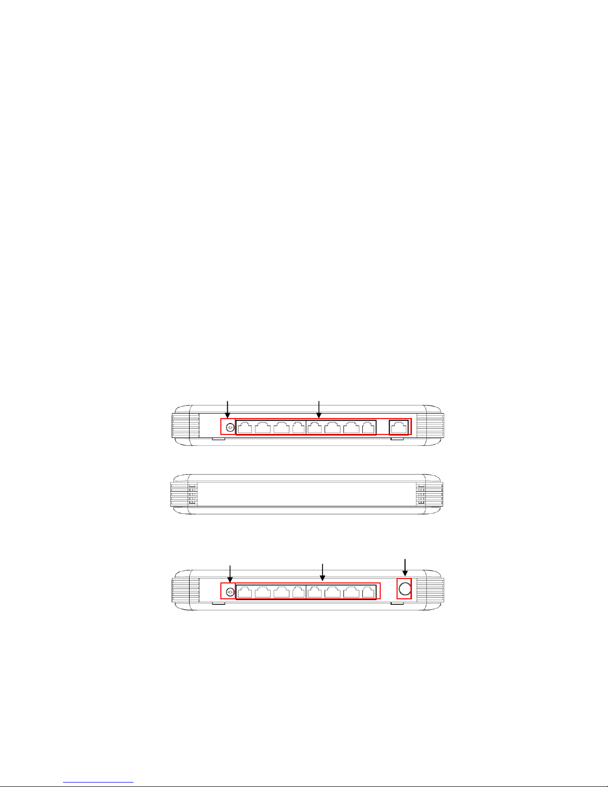
1.1 Interfaces
Depending on the main device and optional accessories that you purchase, the front panel
and rear panel of your Switch may look differently from model to model. The figure 1 & 2
show the front and rear panel for 9-Port 10/100/1000Base-T Management Ethernet Switch
respectively; whereas, the figure 3 & 4 show the front and rear panel for 8-Port
10/100/1000Base-T plus 1-Port 1000Base-X or 100/1000Base-X Uplink Management
Ethernet Switch with optional CATV RF module.
Figure 1: Front Panel for 9-Port 10/100/1000Base-T Management Ethernet Switch
Figure 2. Rear Panel for 9-Port 10/100/1000Base-T Management Ethernet Switch
Figure 3. Front Panel for 8-Port 10/100/1000Base-T plus 1-Port 1000Base-X or
100/1000Base-X Uplink Management Ethernet Switch with optional CATV RF module
Smart Lighting Control
10/100/1000Mbps RJ-45 ports
10/100/1000Mbps RJ-45 ports
CATV RF (Optional)
Smart Lighting Control
6
Figure 4. Rear Panel for 8-Port 10/100/1000Base-T plus 1-Port 1000Base-X or
100/1000Base-X Uplink Management Ethernet Switch with optional CATV RF & Battery
Charging module
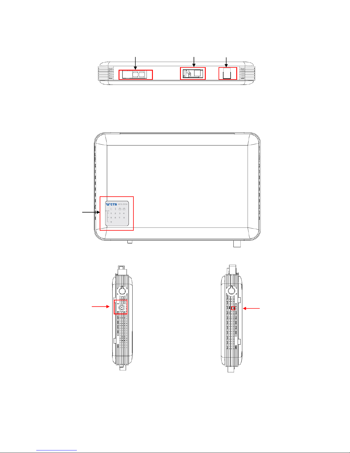
All models have the same top, left and right panel.
Figure 5. Top Panel with LED Indicators
Figure 6. Left Panel Figure 7. Right Panel
1000Mbps F/O port
LED Indicators
CATV RF Input
(Optional)
Battery Charging
(Optional)
Power Jack
Connector
Reset Button

7
1.2 Management Preparations
The Management Ethernet Switch can be accessed through both Telnet connection and a
web browser (will be available in later Firmware version), such as Internet Explorer or
Netscape, etc. Before you can access to the Management Ethernet Switch to configure it,
you need to connect cables properly.
1.2.1 Connecting the Management Ethernet Switch
It is extremely important that proper cables are used with correct pin arrangements when
connecting Management Ethernet Switch to other devices such as switches, hubs,
workstations, etc.
1000Base-X Fiber Port
1x1000Base-X fiber port is located at the rear panel of the Management Ethernet
Switch. This port is primarily used for uplink connection and can operate at 100M/Full
mode. Duplex SC or WDM Simplex SC types of connectors are available. Use proper
multimode or single-mode optical fiber to connect this port with the other Fast
Ethernet Fiber port.
Before connecting to other switches, workstation or media converter, make sure both
sides of the fiber transfer are with the same media type, for example 100Base-FX
Single-mode to 100Base-FX Single-mode, 100Base-FX Multimode to 100Base-FX
Multimode. And check that the fiber-optic cable type matches the fiber transfer model.
To connect to 100Base-FX transfer, use the multimode fiber cable (one side must be
male duplex SC connector type). To connect to 100Base-FX transfer, use the singlemode fiber cable (one side must be male duplex SC connector type).
10/100/1000Base-T RJ-45 Ports
Depending on the model that you purchased, 8 or 9 10/100/1000Base-T RJ-45 ports
are located on the front panel of the Management Ethernet Switch. These RJ-45
ports allow users to connect their traditional copper-based Ethernet/Fast Ethernet
devices into network. All these ports support auto-negotiation and MDI/MDIX autocrossover, i.e. either crossover or straight through CAT-5 cable may be used.
1.2.2 Assigning IP Addresses
IP addresses have the format n.n.n.n, for example 168.168.8.100.
IP addresses are made up of two parts:
The first part (168.168.XXX.XXX in the example) refers as network address identifies
the network on which the device resides. Network addresses are assigned by three
allocation organizations. Depending on your location, each allocation organization

8
assigns a globally unique network number to each network that wishes to connect to
the Internet.
The second part (XXX.XXX.8.100 in the example) identifies the device within the
network. Assigning unique device numbers is your responsibility. If you are unsure of
the IP addresses allocated to you, consult the allocation organization from which your
IP addresses were obtained.
Remember that no two devices on a network can have the same address. If you connect to
the outside, you must change all the arbitrary IP addresses to comply with those you have
been allocated by the allocation organization. If you do not do this, your outside
communications will not operate.
A subnet mask is a filtering system for IP addresses. It allows you to further subdivide your
network. You must use the proper subnet mask for proper operation of a network with
subnets defined.
1.3 LED Definitions
LED
Definition
Color
Operation
Power
Off
System is power down.
Green
System is power up.
System Status
Green
System is working normally.
Green Blinking
When the system is set back to
default factory setting, the Status
LED indicator will blink 3 times in
green.
When the system is upgrading
Firmware, the Status LED indicator
will blink in green every second.
Battery charging
(For BAT models
only)
Green
When battery is installed to the
device, steady green indicates that
the battery is fully charged.
Green Blinking
When battery is installed to the
device, blinking green indicates that
the battery is charging.
Battery
discharging
(For BAT models
only)
Orange
Battery is installed or connected
incorrectly.
Orange Blinking
When battery is installed to the
device, blinking orange indicates
that the battery is in use.
Port link status
Off
Port link is down
Green
Link is up and works under
10/100Mbps.
Green Blinking
Receiving and transmitting data.
Orange
Link is up and works under
1000Mbps.
Orange Blinking
Receiving and transmitting data.

9
1.4 Button Definitions
Button
Operation
Smart Lighting Control
Button
Push this button to turn on or off LED indicators.
When it is turned on, system status LED and port link LEDs
will be turned off. Only power and battery discharging LED
indicators remain on.
Reset Button
Insert a pin or paper clip to press the Reset button for 3
seconds to restart the device.
Insert a pin or paper clip to press the Reset button for 10
seconds to reset the device to factory defaults.

10
2. Command Line Interface (CLI)
This chapter introduces you how to use Command Line Interface (CLI) via Telnet connection,
specifically in:
Configuring the system
Resetting the system
Upgrading newly released firmware
2.1 Remote Console Management-Telnet
You can use Command Line Interface to manage the Management Ethernet Switch via
Telnet session. For first-time users, you must first assign a unique IP address to the
Management Ethernet Switch before you can manage it remotely. Use any one of the RJ-45
ports on the front panel as the temporary management console port to login to the device
with the default username & password and then assign the IP address using IP command in
Global Configuration mode.
Follow steps described below to access the Management Ethernet Switch through Telnet
session:
Step 1. Use any one of the RJ-45 ports on the front panel as a temporary
management console port to login to the Management Ethernet Switch.
Step 2. Run Telnet client and connect to 192.168.0.1. For first-time users, make sure
the IP address of your PC or workstation is assigned to an IP address between
192.168.0.2 and 192.168.0.254 with subnet mask 255.255.255.0.
Step 3. When asked for a username, enter “admin”. When asked for a password,
leave the password field blank and press Enter (by default, no password is
required.)
Step 5. If you enter CLI successfully, the prompt display Switch> (the model name of
your device together with a greater than sign) will appear on the screen.
Step 6. Once you enter CLI successfully, you can set up the Management Ethernet
Switch’s IP address, subnet mask and the default gateway using “IP”
command in Global Configuration mode. The telnet session will be terminated
immediately once the IP address of the Switch has been changed.
Step 7. Use new IP address to login to the Management Ethernet Switch via Telnet
session again.
Limitation: Only one active Telnet session can access the Management Ethernet
Switch at a time.

11
2.2 Navigating CLI
When you successfully access the Management Ethernet Switch, you will be asked for a
login username. Enter your authorized username and password, and then you will be
directed to User mode. In CLI management, the User mode only provides users basic
functions to operate the Management Ethernet Switch. If you would like to configure
advanced features of the Management Ethernet Switch, such as, VLAN, QoS, Rate limit
control, you must enter the Configuration mode. The following table provides an overview of
modes available in this Management Ethernet Switch.
Command Mode
Access Method
Prompt Displayed
Exit Method
User mode
Login username &
password
Switch>
logout
Privileged mode
From user mode, enter
the enable command
Switch#
disable, exit, logout
Configuration
mode
From the enable mode,
enter the config or
configure command
Switch(config)#
exit
NOTE: By default, the model name will be used for the prompt display. You can change
the prompt display to the one that is ideal for your network environment using the “hostname” command. However, for convenience, the prompt display “Switch” will be used
throughout this user’s manual.
2.2.1 General Commands
This section introduces you some general commands that you can use in User, Enable, and
Configuration mode, including “help”, “exit”, “history” and “logout”.
Entering the command…
To do this…
Available Modes
help
Obtain a list of available
commands in the current mode.
User Mode
Privileged Mode
Configuration Mode
exit
Return to the previous mode or
login screen.
User Mode
Privileged Mode
Configuration Mode
history
List all commands that have been
used.
User Mode
Privileged Mode
Configuration Mode
logout
Logout from the CLI or terminate
Telnet session.
User Mode
Privileged Mode

12
2.2.2 Quick Keys
In CLI, there are several quick keys that you can use to perform several functions. The
following table summarizes the most frequently used quick keys in CLI.
Keys
Purpose
tab
Enter an unfinished command and press “Tab” key to complete the
command.
?
Press “?” key in each mode to get available commands.
unfinished
command
followed by ?
Enter an unfinished command or keyword and press “?” key to complete
the command and get command syntax help.
Examples:
Switch#h?
help Show available commands
history Show history commands
Switch#he?
<cr>
Switch#help
Up arrow
Use Up arrow key to scroll through the previous entered commands,
beginning with the most recent key-in commands.
Down arrow
Use Down arrow key to scroll through the previous entered commands,
beginning with the commands that are entered first.
2.2.3 Command Format
While in CLI, you will see several symbols very often. As mentioned above, you might
already know what “>”, “#” and (config)# represent. However, to perform what you intend the
device to do, you have to enter a string of complete command correctly. For example, if you
want to assign IP address for the Management Ethernet Switch, you need to enter the
following command with the required parameter and IP, subnet mask and default gateway:
IP command syntax: Switch(config)#ip address [A.B.C.D] [255.X.X.X] [A.B.C.D]
Switch(config)#ip address 192.168.1.198 255.255.255.255 192.168.1.254
This means that
you are in Global
Configuration mode
This allows you to
assign IP address.
Enter the IP address, subnet mask, and
default gateway address.
Hostname

13
The following table lists common symbols and syntax that you will see very frequently in this
User’s Manual for your reference:
Symbols
Brief Description
>
Currently, the device is in User mode.
#
Currently, the device is in Privileged mode.
(config)#
Currently, the device is in Global
Configuration mode.
Syntax
Brief Description
[ ]
Brackets mean that this field is required
information.
[A.B.C.D ]
Brackets represent that this is a required
field. Enter an IP address or gateway
address.
[255.X.X.X]
Brackets represent that this is a required
field. Enter the subnet mask.
[port-based | 802.1p | dscp]
There are three options that you can
choose. Specify one of them.
[1-8191]
Specify a value between 1 and 8191.
[0-7] 802.1p_list
[0-63] dscp_list
Specify one value, more than one value or a
range of values.
For example: specifying one value
Switch(config)#qos 802.1p-map 1 0
Switch(config)#qos dscp-map 10 3
For example: specifying three values
(separating by a comma)
Switch(config)#qos 802.1p-map 1,3 0
Switch(config)#qos dscp-map 10,13,15 3
For example: specifying a range of values
(separating by a hyphen)
Switch(config)#qos 802.1p-map 1-3 0
Switch(config)#qos dscp-map 10-15 3

14
2.2.4 Login Username & Password
Default Login
When you enter Telnet session, a login prompt for username and password will appear to
request a valid and authorized username and password combination. For first-time users,
enter the default login username “admin” and “press Enter key” in password field (no
password is required for default setting). When system prompt shows “Switch>”, it means
that the user has successfully entered the User mode.
For security reasons, it is strongly recommended that you add a new login username and
password using User command in Configuration mode. When you create your own login
username and password, you can delete the default username (admin) to prevent
unauthorized access.
Forgot Your Login Username & Password?
If you forgot your login username and password, you can use the “reset button” to set all
configurations back to factory defaults. Once you have performed system reset to defaults,
you can login with default username and password. Please note that if you use this method
to gain access to the Management Ethernet Switch, all configurations saved in Flash will be
lost. It is strongly recommended that a copy of configurations is backed up in your local
hard-drive or file server from time to time so that previously-configured settings can be
restored to the Managed Switch for use when you gain access again to the device.

15
2.3 User Mode
In User mode, only a limited set of commands are provided. Please note that in Use mode,
you have no authority to configure advanced settings. You need to enter Enable mode and
Configuration mode to set up advanced functions of a switch feature. For a list of commands
available in User mode, enter the question mark (?) or “help” command after the system
prompt display Switch>.
Command
Description
exit
Quit the User mode or close the terminal connection.
help
Display a list of available commands in User mode.
history
Display the command history.
logout
Logout from the Management Ethernet Switch.
enable
Enter the Privileged mode.
2.4 Privileged mode
The only place where you can enter the Privileged (Enable) mode is in User mode. When
you successfully enter Enable mode, the prompt will be changed to Switch# (the model
name of your device together with a pound sign). Enter the question mark (?) or help
command to view a list of commands available for use.
Command
Description
copy-cfg
Restore or backup configuration file via FTP or TFTP server.
configure
Enter Global Configuration mode.
disable
Exit Enable mode and return to User Mode.
exit
Exit Enable mode and return to User Mode.
firmware
Upgrade Firmware via FTP or TFTP server.
help
Display a list of available commands in Enable mode.
history
Show commands that have been used.
logout
Logout from the Managed Switch.
reload
Restart the Managed Switch.
write
Save your configurations to Flash.
show
Show a list of commands or show the current setting of each listed command.
2.4.1 Copy-cfg command
Use “copy-cfg” command to backup a configuration file via FTP or TFTP server or restore
the Management Ethernet Switch back to the defaults or to the defaults but keep IP
configurations.
1. Restore a configuration file via FTP or TFTP server.
Command
Parameter
Description
Switch# copy-cfg
from ftp [A.B.C.D]
[file name]
[user_name]
[password]
[A.B.C.D]
Enter the IP address of your FTP server.
[file_name]
Enter the configuration file name that you
want to restore.
[user_name]
Enter the username for FTP server login.
[password]
Enter the password for FTP server login.
 Loading...