

®
Commercial
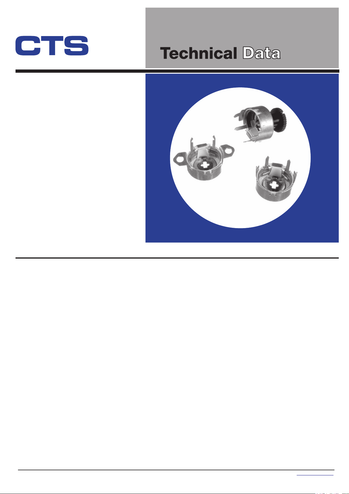
3
/4" (19mm)
1
Diameter, 1
/2 and 2
Watt Wirewound
Variable Resistors
Features
• Inexpensive design
• Open construction
• Four mounting styles
• Incorporated fixed resistor available
Series 110
• Available with nylon knob
• Interchangeable mounting with
CTS Series 115 preset potentiometer
• RoHS compliant
Electrical and Mechanical Specifications
Resistance Range
1 ohm through 10K ohms (linear taper)
Resistance Tolerance
Standard:±20%
Special:±5% or 10%
Power Rating, Watts
2 watts @ 55°C derated to no load @ 105°C,
mounted on steel panel
1.5 watts @ 55°C derated to no load @ 105°C,
mounted on bakelite panel
Voltage Rating
Determined by resistance value and wattage rating
Resistance Taper
Standard:Linear taper only
Minimum Resistance
At ends of rotation: 1% or 1 ohm, whichever is greater
Resistance Taper
None
Incorporated Fixed Resistor
A fixed resistor can be incorporated in the Series 110
at the end of CW or CCW rotation to a minimum of 10%
of the total resistance. The rotation is shortened by an
amount proportional to the ratio of the fixed resistor to
the total resistance. Available at extra cost.
Angle of Rotation
Resistor Adjustment
Mounting Types Available
Rotational Torque
Terminals
246°±5°without fixed resistor stop
Standard Cross Slot: Provided in drive plate for screwdriver
adjustment.
Special Molded Knob: Available at extra cost secured to
drive plate cross slot.
Type 110: Solder or clinch-ear mounted
Type XPC - 110: Vertically mounted on printed circuit board
Type 111: Snap-in mounting
Type 112: Eyelet or rivet mounting
1
/2 to 10 inch ounces (36 – 720 gf-cm)
Terminals at end of CW or CCW rotation may be omitted.
Refer to terminals on all types by numbers 1 and 3 as
indicated on line drawings.
1 - 3 © 2006 CTS Corporati on. All ri ghts reserved. Informati on subject to change. 9/30/06
CTS Electronic Components www.ctscorp.com

Type 110, Solder or Clinch-Ear Mounted, Long Terminal Length
17.86
.703
1.57
.062
10.72
.422
7.14
.281
PRINTED CIRCUIT PANEL
5.56
.219
16.66
.656
2.39
.094
5.56
.219
TERM 1.98 x 0.40
4.37
.172
.078
.014
1.52
.060
END C.C.W. ROT.
NO. 1 TERM
246°
19.94
.785
SCREWDRIVER
ADJUSTMENT SLOT
KNOB OPTIONAL
14.30
.563
57°57°
END C.W. ROT.
NO. 3 TERM
11.13
.438
U - Long Terminal Length
TYPE M110, Solder Mounted, Medium Terminal Length
14.68
1.57
.062
10.67
.420
.578
4.44
.175
PRINTED CIRCUIT PANEL
2.39
1.98 x 0.36
.014
.078
2.87
.113
REF.
.094
8.43
.332
1.52
.060
end c.w. rot.
no. 1 terminal
19.9±0.4
.783±.016
rot
246°
57°
57°
screwdriver
adjustment slot
end c.w. rot.
no. 3 terminal
KNOB OPTIONAL
14.3
.562
11.1
.437
MIN.
MIN.
20.58±0.05
.810±.002
10.29±0.05
.405±.002
40°
1.40
.055
2.79±0.05
.110±.002
20.58±0.05
.810±.002
10.29±0.05
.405±.002
40
1.40
.055
2.79±0.05
.110±.002
2.79±0.05
1.40
.110±.002
.055
9.40±0.05
.370±.002
40°
40°
°
1.5
.060
1.40
.055
9.40±0.05
.370±.002
1.5
.060
DIMENSION:
2.79±0.05
.110±.002
INC
mm
H
M - Medium Terminal Length
TYPE XPC110, Vertically Mounted
23.42
.922
4.75
.187
246°
12.7
.500
END C.C.W. ROT.
NO. 1 TERM
21.59
.850
57°
57°
END TERMINAL
1.98X.081
.078 .032
END C.W. ROT.
NO. 3 TERM
11.91
.469
CENTER TERMINAL
1.98X0.41
.078 .016
28.17
1.109
15.24
.600
7.62
.300
2.77 DIA.
.109
5.77
.227
DIMENSION:
DIMENSION:
INC
INC
mm
H
mm
H

Type 111, Snap-In Mounted
END C.C.W ROT
NO.1 TERM
KNOB OPTIONAL
14.3
.563
19.94
.785
END C.W
NO.3 TERM
ROT
57°
21.59
246°
.850
57°
EWDRIVER
SCR
TMENT SLOT
ADJUS
Type 112, Eyelet or Rivet Mounted
240°
ROT.
31.75
1.25
25.4
1.000
KNOB OPTIONAL
MOUNTING PANEL
11.13
.438
MOUNTING PANEL
10.72
.422
17.86
.703
5.54
.218
7.14
.281
3.96
.156
5.56
.219
.062
1.57
2.79
.110
.055
20.22
.796
10.11
.398
1.57
.062
1.4
9.40
.370
1
.
5
.
0
2
6
4
0
°
1
.
4
.
0
0
5
5
2
.
7
.
1
9
1
0
0
°
0
4
DIMENSION:
mm
CH
IN
19.94
.785
9.53
END C.C.W
NO.1 TERM
ROT
.375
40°
57°
40°
57°
Ordering Information
110
SERIES MOUNTING
DESIGNATION
110 – CLINCH EAR MOUNT
OR VERTICAL MOUNT
111 – SNAP-IN MOUNT
112 – EYELET MOUNT
X – PC MOUNT (XPC-110 AND 112 ONLY)
U – PC TERMINALS FORMED TO FRONT
(110, 111, 112 ONLY)
M – PC TERMINALS FORMED TO FRONT
MEDIUM LENGTH (110 ONLY)
3.45
.136
ROT
END C.W
NO.3 TERM
SCR
EWDRIVER
TMENT SLOT
ADJUS
U
TERMINAL STYLE
14.3
.563
TERM LOC. A
1.98/.078 X 0.4/.016
A
KNOB OPTION
A – NO KNOB
B – .438" (11.1mm)
LONG KNOB
TERMS
11.13
.438
1.57
.062
9.53
.375
RESISTANCE CODE
CODERESISTANCE
5A0 5 OHMS
500 50
101 100
501 500
102 1K
252 2.5K
502 5K
103 10K
203 20K
OPTIONAL TERM LOC. B
1.57
.062
8.74
.344
103 B
EXAMPLES
RESIST TOL
A – ±10%
B – ±20%
D – ± 5%
R8.64
.340R.
25.4
1.000
40°40°
TAPER
1 – LINEAR
12.7
.500
1
Ø3.45
.136
DIA
. OF HOLE TO SUIT
TERM CLEA
DIMENSION:
RANCE.
mm
CH
IN
3 - 3 © 2006 CTS Corporati on. All ri ghts reserved. Informati on subject to change. 9/30/06
CTS Electronic Components www.ctscorp.com
 Loading...