

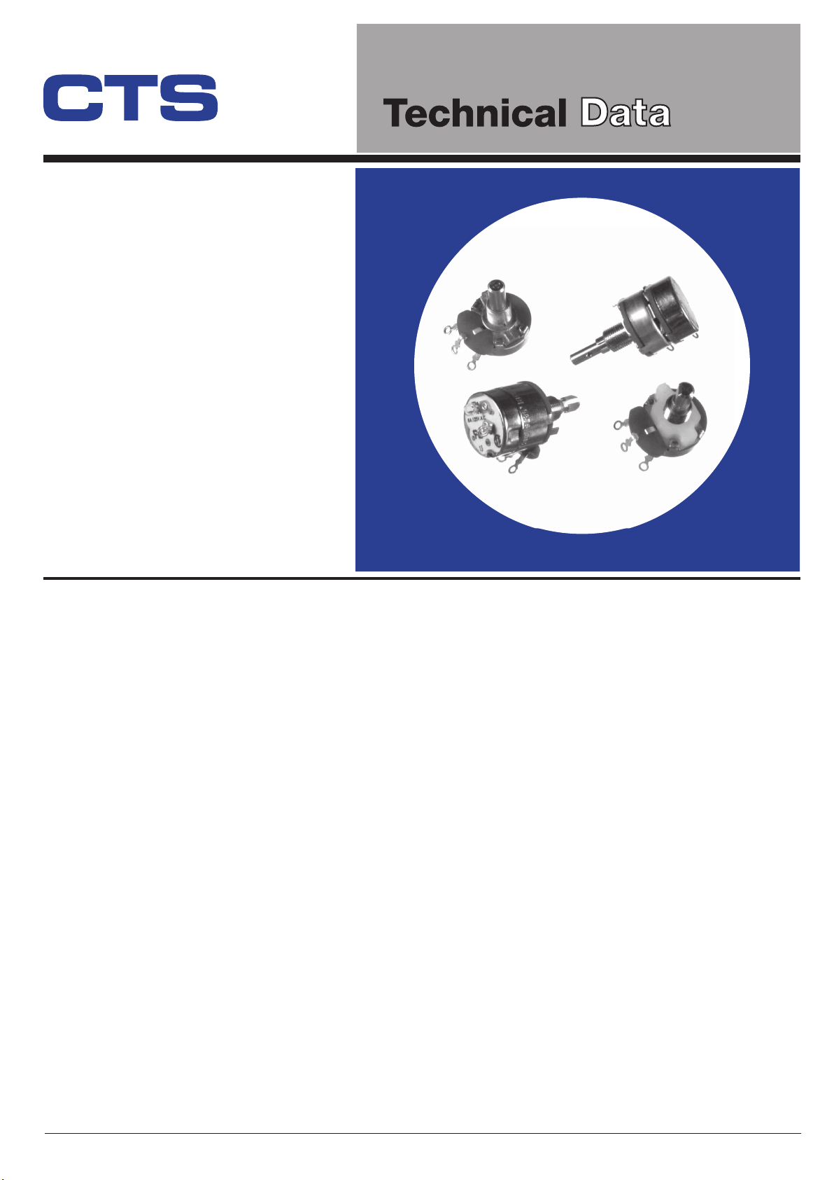
Series 026
®
Industrial
(24mm)
15/16"
Diame
ter,
5-Watt, Wirewound
Variable Resistors
Features
• Dust-proof construction
Water splash proof construction available
•
5-watt power rating
•
• Superior resistance stability in temperature
and environment change
•
Tandem constructions available
• Bushing or twist tab mounting
• Available with pull-push and rotary
power switches
• Excellent linearity performance
• RoHS compliant
Electrical and Mechanical Specifications
Resistance Range
Linear : 1 ohm through 25K ohms
Audio : 20 ohms through 10K ohms
Resistance Tolerance
Standard : ± 10%
Special : Tighter tolerance available in most
resistance values
Power Rating
5 watts @25°C, 4 watts @ 55°C, derated to
no load at 105°C, linear taper
(Derating required on two section countols.)
Voltage Rating
Bushing to Terminals:
High pot test, one minute -- 1,000 VAC
Operating maximum -- 500 VDC
Across End Terminals:
350 VDC maximum, load not to exceed
wattage rating.
Resistance Tapers
Linearity
Power Swi
Rotational Angle
Rotational Torque:
Standard: Linear or 20% audio
Special: Consult CTS
Standard: 3% linea
Special: Consult CTS
tches
Rotary Pole-SPST, DPST & SPDT
Pull-Push Pole-SPST (Pull-ON, Push-OFF)
Mechanical Rotation:
Without switch: 300°±5°
With switch: 300°±5°
Effective Rotation:
Without switch: 280°±5°
With switch: 265°±5°
Standard: 3/4 to 6 in. oz (54 - 432 gf-cm)
Special: higher torque models available, consult CTS
Operating Tempera
-30°C to +85°C
rity
ture
(continued on next page)
1 - 4 © 2006 CTS Corporation. All rights reserved. Information subject to change. 10/15/06
CTS Electronic Components www.ctscorp.com

Shaft Information
Available for round, flatted, knurled, or slot metal shaft
Diameter: 6.35mm (.250")
Shaft Center to Lug
Standard: .438" (11.1mm)
Special: .531" (13.5mm) available
Consult CTS for custom-made metal and economic plastic shaft
Special Features and Constructions
Mounting Information
Bushing Mount
Diameter: EIA standard 3/8-32 UNEF-2A thread
Standard length: 9.53mm (.375") or 6.35mm (.250")
Consult CTS for custom-made metal and economic plastic
bushing
Twisted Tab Mounting Available
Locating Lugs
Standard: Left lug with terminals facing inward
Terminals accepting push-on connectors available.
Straight or concentric tandem constructions.
Can be combined with 450 series, 15/16" (24mm) diameter,
to make any combination of straight or concentric tandem
constructions with or without switch.
Long life constructions available.
Long Life Construction
This construction provides an extended life of 50K and 100K
cycles. Consult CTS for details.
Available: No lug, right lug or two lugs with terminals
facing inward
T026 Metal Shaft, Bushing Mounting, Type "T" Solder Lug Terminals
CLEARANCE HOLE
1.57±0.08
.062±.003
MOUNTING HOLE DE
CCW
1 3
4.16±0.08
.164±.003
±0.08
10.41
.410
±.003
CLOCKWISE
CIRCUIT
±0.08
10.41
.410
±.003
2
WIPER
TAIL
CW
2.08±0.08
.082±.003
1.57±0.08
.062±.003
DIMENSION:
11.9
.469
8.
3
2Ø
MTG. SURFACE
3/8-32 UNEF-2
739.
±0.4
"A"
±.016
±0.8
"L"
±.031
A
3.18
.125
1
TERMINA
L (3) HOLES Ø2.18 /.086
2
22.2
.875
11.1
.437
MAX.
.XAM
0
8
.91
87.
3
X026 / Y026 Metal Shaft, Bushing Mounting, Printed Circuit Type X/Y Terminals
MTG. SURFACE
±0.4
"A"
±.016
mm
inch
11.1
.437
3.18
8
739.
.
32Ø
3/8-32NEF-2A
"L"±0.8
±.031
.125
4.0
.156
1 2
TYP.
7.92
.312
17.5
X=
.687
22.0
Y=
.867
3
.191
4.9
Ø2.08±0.05
.082±.002
(6) HLS.
MOUNTING HOLE DETAIL
CCW
MTG. SURFACE
2.03±0.05
.080±.002
TYP.
7.92
.312
WIPER
2
1 3
CLOCKWISE
CIRCUIT
CW
3.68
.145
F.
RE
DIMENSION:
mm
inch
2 - 4 © 2006 CTS Corporation. All rights reserved. Information subject to change. 10/15/06
CTS Electronic Components www.ctscorp.com

U026 Metal Shaft, Bushing Mounting, Printed Circuit Type “U” Formed Terminals
(2)
±0.08
10.41
.410
±.003
7.87
2
CLOCKWISE
CIRCUIT
(2)
.31
WIPER
CLEARANCE HOLE
14.83
.58
Ø2.54
(3)
.1
CW
DIMENSION:
MTG. SURFACE
11.9
.469
11.1
.437
4.16±0.08
.164±.003
3.18
.125
8.
739.
3
2Ø
"L"
3/8-32 UNEF-2A
"A"
±0.8
±.031
±0.4
±.016
1
22.2
.875
2
MAX.
3
MOUNTING HOLE DE
(2)
(2)
1.57±0.08
.062±.003
CCW
1 3
TAIL
V026 Metal Shaft, Bushing Mounting, Printed Circuit Type “V” Formed Terminals
34.5
1.36
REF.
4.16±0.08
.164±.003
11.9
.469
8.
73
3
9.
2Ø
MTG. SURFACE
3/8-32 UNEF-2A
±0.4
"A"
±.016
±0.8
"L"
±.031
3.18
.125
11.1
.437
1
2
22.2
MAX.
.875
CCW
1 3
3
CLOCKWISE
CIRCUIT
.XAM
0
8
.91
87.
1.57±0.08
.062±.003
±0.08
±0.08
10.41
10.41
.410
.410
±.003
±.003
MOUNTING HOLE DETAIL
7.92(2)±0.05
.031±.002
WIPER
2
CW
2.03±0.05
.080±.002
PCB LAYOUT
CLEARANCE HOLE
±0.08
10.41
.410
±.003
Ø2.08±0.05
2.08±0.08
.082±.003
1.57±0.08
.062±.003
.082±.002
DIMENSION:
mm
inch
mm
inch
S026 Metal Shaft, Bushing Mounting, Faston Type “S” Formed Terminals
MTG. SURFACE
11.9
.469
3/8-32 UNEF-2A
11.1
.437
3.18
8.32Ø
739.
±0.4
"A"
±.016
±0.8
"L"
±.031
.125
1
22.2
.875
2
MAX.
8.0
.315
3
3 - 4 © 2006 CTS Corporation. All rights reserved. Information subject to change. 10/15/06
CTS Electronic Components www.ctscorp.com
CLEARANCE HOLE
4.16±0.08
.164±.003
±0.08
1.57±0.08
.062±.003
±0.08
10.41
10.41
±.003
±.003
MOUNTING HOLE DETAIL
CCW
1 3
±0.08
10.41
.410
.410
±.003
2
CLOCKWISE
CIRCUIT
.410
WIPER
CW
2.08±0.08
.082±.003
1.57±0.08
.062±.003
DIMENSION:
mm
inch

VPE026 Metal Shaft, Twist TAB Mounting, Type “V” Formed Terminals
MTG. SURFACE
11.9
.469
±0.8
“L”
±.031
.FER
5.43
8
.32Ø
853.1
739.
8.33
.328
3.96
.156
CENT.
CENT.
1
22.2
.875
23.5
.925
21.1
.832
2
MAX.
MIN.
MAX
3
7.92(2)±0.05
.031±.002
2.03±0.05
.080±.002
CCW
PCB LAYOUT
WIPER
2
1 3
CLOCKWISE
CIRCUIT
Ø2.08±0.05
.082±.002
CW
CLEARANCE HOLE
4.17
CENT
.164
1.57
.062
10.41
.410
MOUNTING HOLE DE
* Consult CTS for details
T2-026 Dual-section, Metal Shaft, Bushing Mounting, Type “T” Solder Lug Terminals
23.0
.906
(P)(R)
8.
739.
3
2
TERMINAL HOLES Ø2.18/.086
* More multi-section models available, consult CTS for details
MTG. SURFACE
±0.8
"L"
±.031
3/8-32 UNEF-2
±0.4
"A"
±.016
3.18
.125
11.1
.437
1
4
2
5
22.2
.875
3
6
MAX.
CLEARANCE HOLE
4.16±0.08
WIPER
CCW
1 3
XAM
0
8
.91
87.
2
5
CLOCKWISE
CIRCUIT
WIPER
CW
64
1.57±0.08
.062±.003
.164±.003
±0.08
10.41
.410
±.003
±0.08
10.41
±.003
MOUNTING HOLE DETAIL
.410
10.41
.410
1.57
.062
TAIL
DIMENSION:
2.08±0.08
.082±.003
1.57±0.08
.062±.003
DIMENSION:
mm
inch
mm
inch
Ordering Information
026 T 2 20 R 103 B 1 A 1
TERMINAL STYLE
T - SOLDER LUG
X - PC .687”(17.5mm)
Y - PC .867”(22.0mm)
U - FORMED
TO FRONT
V - FORMED
TO REAR
S - FASTON
METAL SHAFT LENGTH “L”
FROM MOUNTING SURFACE
1/32"INCREMENTS
EXAMPLES:
20 - .625"(6.35mm)
24 - .750"(19.5mm)
28 - .875"(22.2mm)
32 - 1.000"(25.4mm)
* CONSULT CTS FOR
SPECIAL REQUIREMENTS
METAL MOUNTING
STYLE “A”
BUSHING LENGTH:
1/8" INCREMENTS
EXAMPLES:
2 - .250"(6.35mm)
3 - .375"(9.53mm)
8 - 1.000"(25.4mm)
1 - TWIST TAB
MOUNT
A - .250"(6.35mm)
DIECAST
B - .375"(9.53mm)
DIECAST
SHAFT TRIM
R - ROUND
F - FLATTED .375"X.156"
(9.53mmX4.0mm)
K - KNURLED
EIA S148 24 TEETH
S - SD SLOT .063" DEEP
X.047" WIDE
(1.6mmX1.2mm)
RESISTANCE CODE
EXAMPLES
CODE RESISTANCE
5A0 5 OHMS
501 500 OHMS
102 1K
252 2.5K
502 5K
103 10K
253 25K
RESIST TOL
A - ±10%
B - ±20%
D - ±5%
TAPER
1 - LINEAR
2 - 20%AUD
3 - 20%CCW AUD
SWITCHES FUNCTION CTS TYPE CURRENT RATING
A - NONE
B - SPST ROTARY TGC 6AMP@125VAC
C - DPST ROTARY 027 3AMP@125VAC
D - SPDT ROTARY 028 3AMP@125VAC
E - SPST PULL-PUSH FR-K 3AMP@125VAC
F - SPST ROTARY FR-GC 3AMP@125VAC
* CONSULT CTS FOR DETAILS
SPECIALS
1 - LOCATING
LUG LEFT
SIDE
2 - LOCATING
LUG RIGHT
SIDE
3 - NO
LOCATING
LUG
5 - LOCATING
LUG BOTH
SIDE
1AMP@250VAC
1AMP@250VAC/DC
4 - 4 © 2006 CTS Corporation. All rights reserved. Information subject to change. 10/15/06
CTS Electronic Components www.ctscorp.com
 Loading...