

Page 1
www.ctronicssecuritycameras.com
1
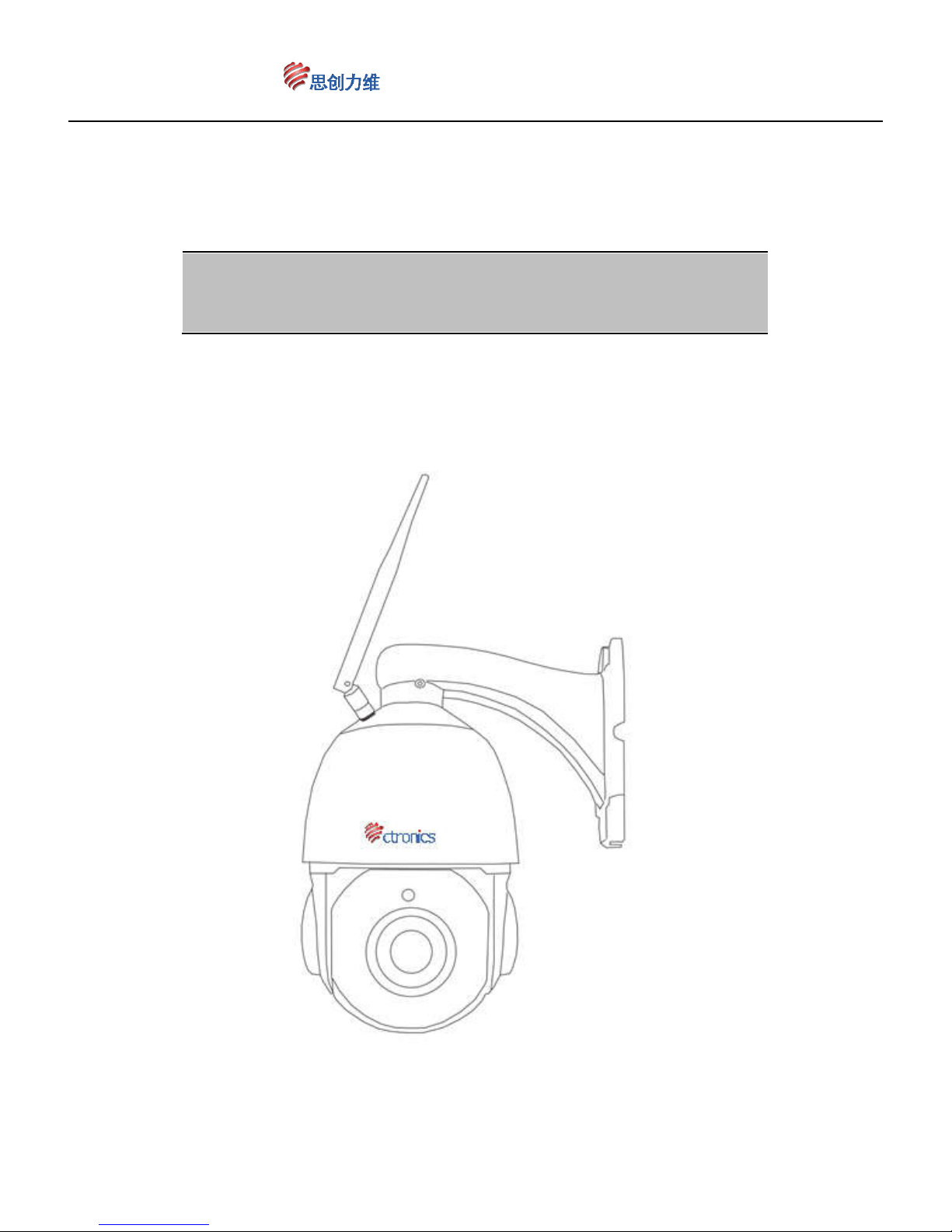
Wireless WIFI hot point mini dome camera
Camera integrated speed dome
user manual
Page 2

www.ctronicssecuritycameras.com
2
CTIPC-260CWS
Please read the installation instructions before you operate it.
Ⅰ:User instructions
Thank you for using our INTELLIGENT SPEED DOME CAMERA
According to our introduction of guarantee,Within the specified warranty period,our
company will repair or replace parts that are damaged under normal use .User don’t
disassemble repair itself without Our Consent. Within the specified warranty period, we
will repair or replace parts (excluding cable, housing and bracket) that are damaged
under normal use (by judge of us) at no additional charge.
Free services and repairs will not be covered under the following conditions
1、 Unauthorized repair or disassembly of the product ;
2、 Damage due to the bad shipping, or Move of discharging ;
3、 Damage due to the user not according to the user manual to operate, maintain,
maintenance,such as falling、extrusion、flooding water、be affected with damp、
corrosion and Other damage caused by human factor ;
4、 The product faulty caused by the overloaded or the working environment which
is not suitable for it, and surface damaged when you using it ;
5、 Any damage or ruin by force majeure.
Friendly suggestion : in order to realize the whole function of our products ,
Compatibility tests must be conducted before using a third-party product In the
system .
Ⅱ、Product feature
4" elegant appearance,housing rotates follow the camera lens, IR light will not
be hided by the cover, set the Address Code & Baud Rate, no need to open the
PTZ housing, more convenient.
Drove by bearing and belt, more stable and smooth, long performance life.
Using import belt drive,Running more stable, more reliable and noiseless.
Using import stepper motor,responsive、fixed position accurately.
SEL imported super brightness Array IR LED, effective night vision distance is
80 m.
Control protocol adaptive, communication baud rate adaptive, no more need
Page 3

www.ctronicssecuritycameras.com
3
complexly set, Greatly facilitate the use of the user
Different angles of infrared right according to the changes of the lens
change times lead to visual Angle on or off in stages, make the IR light
illuminate Angle and lens viewing angles consistent, effectively solve the
ordinary infrared machine due to the small Angle change times high power IR
light in the visual Angle when open comes to the lens "flashlight" phenomenon,
and make the irradiation Angle difference from the viewing Angle of current
camera for the IR light producing periodic rest, reduce the infrared lamp panel
working current, effectively control components of dark current and calorific
value, greatly improved the integration of cameras work environment. Really
improve the machine service life and stability.
Decoder board supply power to motor, camera and IR LED separately,
machine can works more stable.
Using conducting ring, realize continuously rotate for 355° and avoid the
wires twist together.
80 preset positions; 8 tour routes, 1 fixed monitoring position, can set
stay time for each preset positions as 5 / 10 / 15/…/ 55 / 60 seconds, can set
limitation positions on left and right, internal data will not lost after power off.
Angle speed:horizontal 355°Rotation 0.1°- 40°/ sec;vertical 0~90°
rotation. 0.1°- 40°/ sec
Ⅲ:Main technical parameters
1、Electricity
Power supply: DC12V—3000mA
Page 4

www.ctronicssecuritycameras.com
4
PTZ drive: DC12V—500mA
IR light power supply: DC12V—1800mA
lens Drive: DC12V—200mA
Camera power supply: DC12V—200mA
Other: DC12V—300mA
Retrofitting Temperature controlling device
Working temperature: -25℃~+55℃
Address range: 1~255
Communication mode: RS485
Protocol:support various protocol
Baud rate: 2400bps、4800bps、9600bps、19200bps Auto
Controlling Equipment: Video Matrix、industrial control DVR、DVR、NVR、controlling
keyboard etc.
Preset: 255 presets,1-80 for dome, other for special function
inspection teams:8 groups
stay time for each preset positions:5*n seconds adjustable (1≤n≤20).
2、
Mechanical Specifications
PTZ rotation angle: horizontal 355°unlimited rotation, vertical 0
°~
90
°
PTZ rotation speed: horizontal
0.1°- 40°
/ sec,vertical
0.1°- 40°
/ sec
Rotation limit:horizontal is adjustable in the range PTZ rotation angle of 355
°,
software and photoelectricity limit
3、Environment
Working temperature
:
-25
℃ ~
+55
℃ (
temperature control): Built-in 45
℃
environment temperature.
Working humidity: 90% RH
Ⅳ:Setup connection and Matching device
Page 5
www.ctronicssecuritycameras.com
5
1、
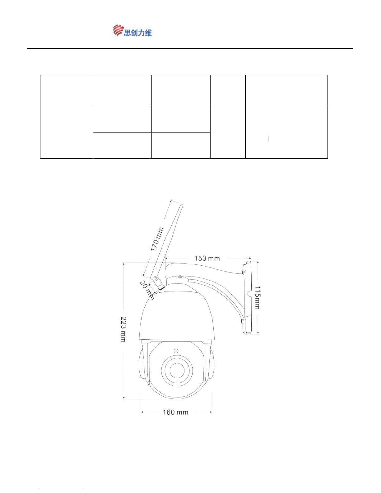
matching device such as Table 1:
Table 1:
matching device
Product Installation Holder Power
High Speed
Dome
wall
mounting
wall bracket
DC12V
3A
The power cable
NET
hoisting
hoisting
bracket
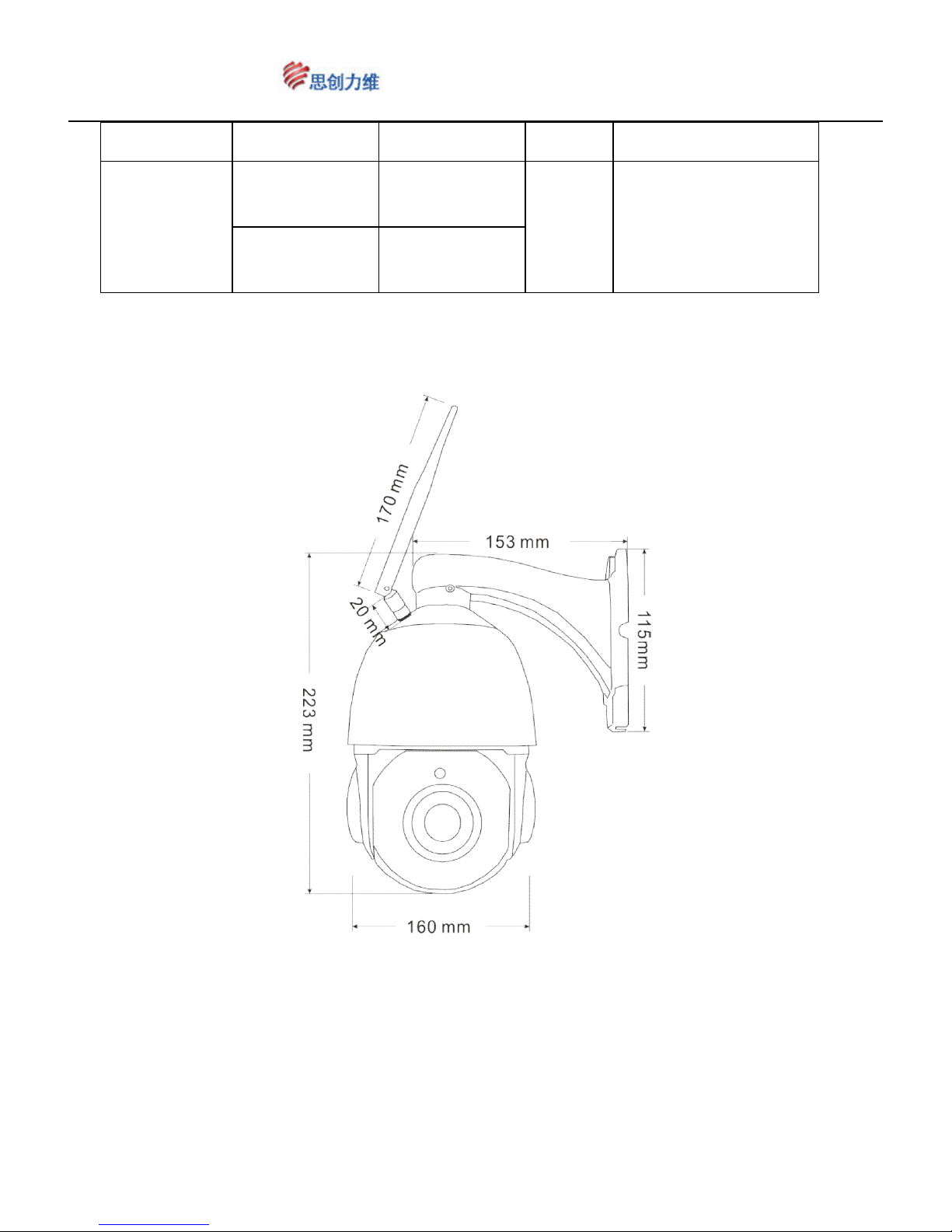
SIZE PHOTO
cable
,
cable
Page 6
www.ctronicssecuritycameras.com
6
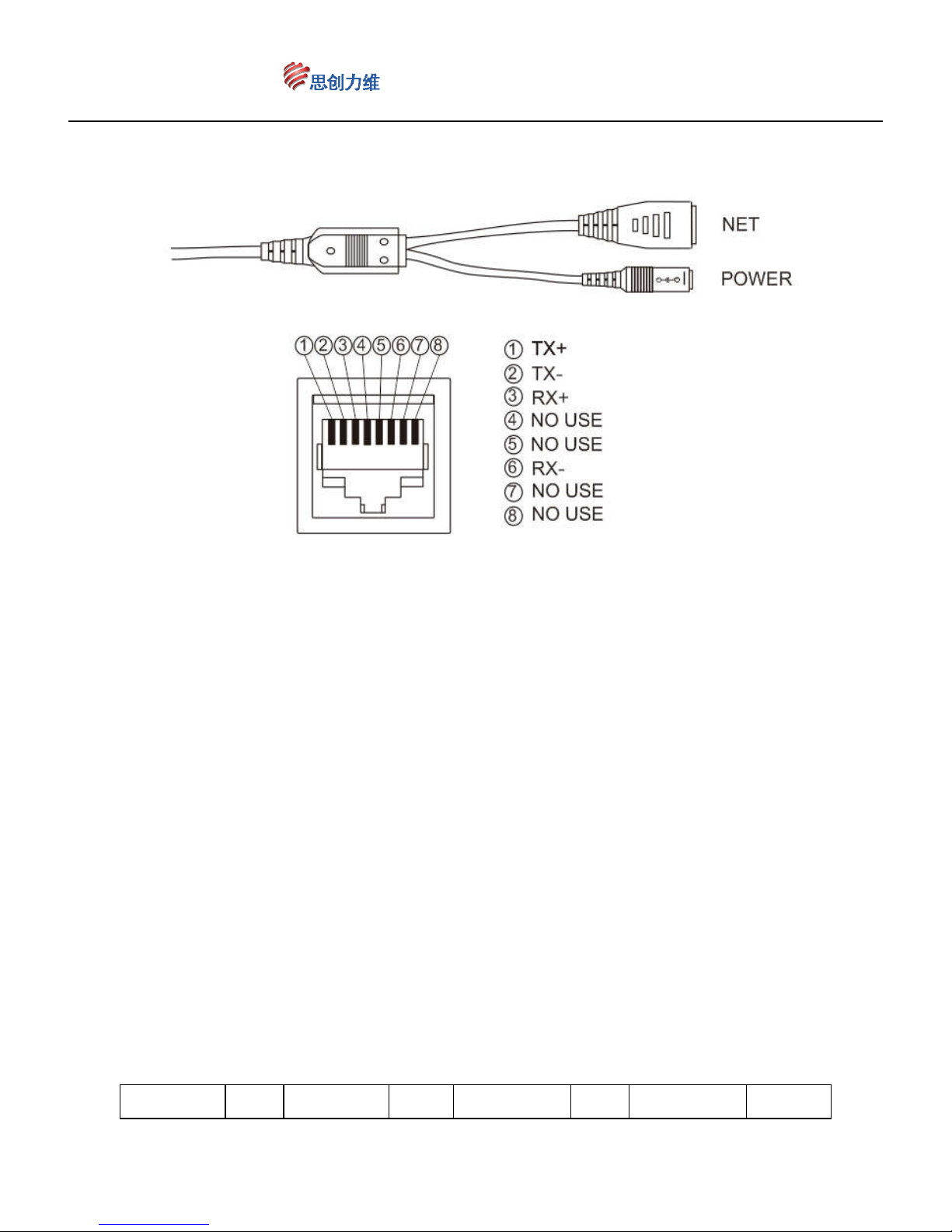
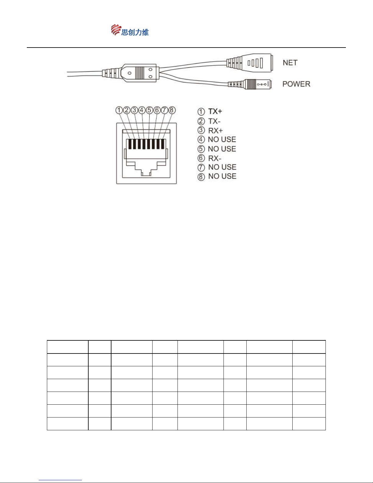
3、IP dome signal of the camera and power cable connection please reference
chart
Ⅴ:Address, Protocol, Baud rate setting
Integrated High Speed Dome Camera built-in decoder .You can setting the
address, the Protocol and the baud rate are adaptive. This product designed the
dial switch located on the sphere, given the set of convenient and stability,
there is a piece of gusset plate under the ball cover which can open and close at any time.
Open the gusset plate can see an 8-bit dial switch.1-8 of dial up used to set address
code of the dome.
1、Address setting
No.1~ No.8 are use to set the address codes of the bits dial switch, you can set
address codes within the range 1~255, factory default as 1. Use binary, dial every
number to be "ON" is means as 1, dial to be "OFF" is means as 0, details please
reference the sheet 2.
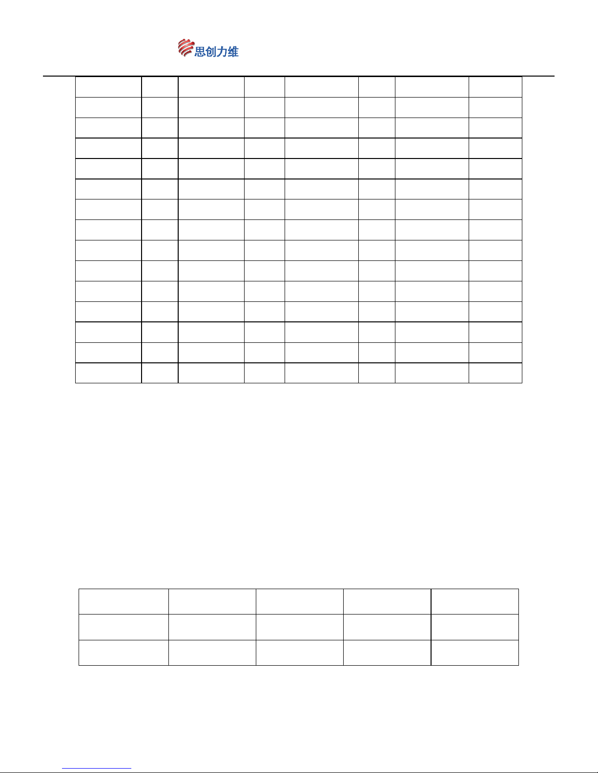
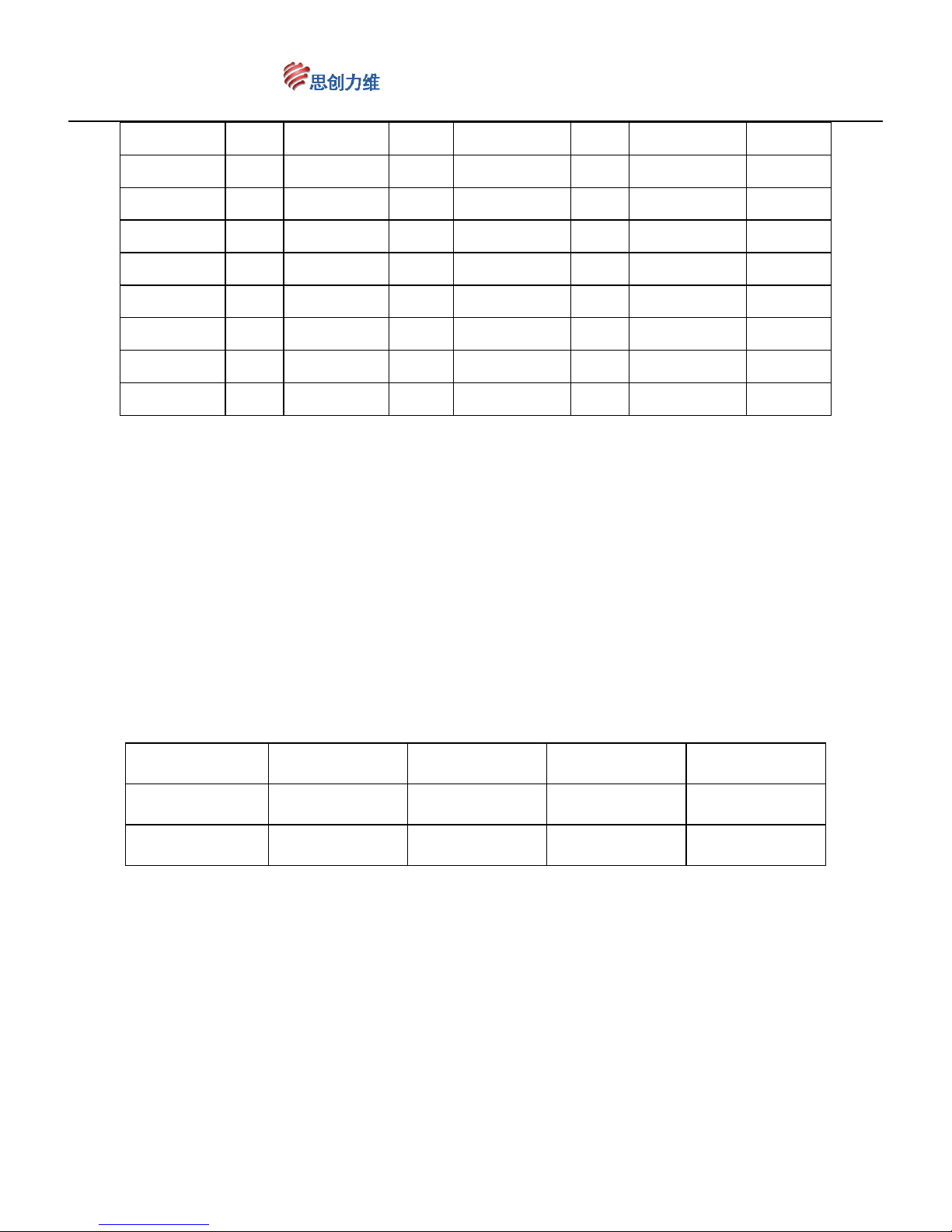
Address codes and dial codes switch sheet (Binary), calculate it according to
this sheet:
Binary Add Brinary
Add
Binary Add
Brinary Add
Page 7
www.ctronicssecuritycameras.com
7
00000000
0 11110000
15 01111000 30 10110100 45
10000000
1 00001000
16 11111000 31 01110100 46
01000000
2 10001000
17 00000100 32 11110100 47
11000000
3 01001000
18 10000100 33 00001100 48
00100000
4 11001000
19 01000100 34 10001100 49
10100000
5 00101000
20 11000100 35 01001100 50
01100000
6 10101000
21 00100100 36 11001100 51
11100000
7 01101000
22 10100100 37 00101100 52
00010000
8 11101000
23 01100100 38 10101100 53
10010000
9 00011000
24 11100100 39 01101100 54
01010000
10 10011000
25 00010100 40 11101100 55
11010000
11 01011000
26 10010100 41 00011100 56
00110000
12 11011000
27 01010100 42 10011100 57
10110000
13 00111000
28 11010100 43 01011100 58
01110000
14 10111000
29 00110100 44 11011100 59
2、Baud rate setting (The baud rate is adaptive , this part is only the setting of
reference on the previous products)
Baud rate can set through the 4th ~5th dial codes,Can be set up the baud rate to
2400BPS、4800BPS、9600BPS、19200BPS。dial every number to be "ON" is means
as 1, dial to be "OFF" is means as 0,Baud rate and dial codes switch matching sheet
reference sheet 3 .
sheet3:Baud rate and dial codes switch matching sheet
Dial codes
2400 bps 4800 bps 9600 bps 19200 bps
No.4
OFF ON OFF ON
No.5
OFF OFF ON ON
3、Protocol setting
Page 8

www.ctronicssecuritycameras.com
8
Decoder of Speed dome will automatically match protocol,you don't need to set;
PELCO_D、PELCO_P support PELCO_D and PELCO_P
Ⅵ:Function setting
1、Set/call preset
Preset function refers to through controlling equipment setting / call IR dome position
parameters of the horizontal Angle and vertical Angle, by storing in digital form to the IR
dome, when needs to call these parameters, adjust the IR dome to preset a set state.
Operator can control it convenient and efficient through controlling keyboard and other
devices to set/call preset position. This IR dome camera supports 255 presets.
(1)Set preset position
Make the IR dome moved to the corresponding position by controlling keyboard, DVR
and other control equipments,You can refer to the Preset function of controlling
keyboard or DVR to process preset settings after using the zoom buttons of the
controlling keyboard, DVR etc controlling devices to adjust Multiples of the lens to right
angle, and enter the corresponding number of preset position
Example:Using a type of controlling keyboard to set No.1 preset position
a、Press the key “set preset”,then the camera is moved to the need position by joystick.
Make the lens step to the angle in demand by pressing the key “zoom”
b、 Enter “1”
c 、Press the key “enter”
(2)Call preset
Refer to the calling preset function of controlling keyboard or DVR to process preset
calling, and according to the required preset position number to call.
Page 9
www.ctronicssecuritycameras.com
9
Example:using a type of controlling keyboard to call No.1 preset position.
a、Press the key“ call preset position”, then enter “1”
b、Click‘Enter’
2、
Calling of automatically cruise routes/clear
Auto tour is by operation to set the cruise routes arbitrarily ,an external command
can let the dome camera according to the specified route to make a tour
automatically,and staying in the corresponding preset position。there are 8 auto
cruise routes for the IR dome camera,Each tour lines can store up to 5 presets at
least and 30 presets at most .
(1)Calling auto tour line
By controlling keyboard and DVR to implement the command “call No.98”preset
position. It can make the dome camera auto tour the preset position of it has been set
in the first cruise route “call No.97 preset position” as auto tour the preset position of
the second tour line. Corresponding number of preset position for 3cruise routes, please
reference table 5.
Table 5:cruise and preset relation table
Patrol line Calling preset Contains preset
the first cruise call No.98 preset
1~5 preset
the second cruise call No.97 preset
6~15 preset
The third cruise call No.96 preset
16~35 preset
Note. : The default preset position number corresponding to each patrol
as shown in the table, but the you can be added to each of 30 presets .
Example:Use a type of controlling keyboard to start using the second auto tour line.
a、Press the key “call preset position”, then enter “97”
b、press the key “Enter”
(2)Stay time setting for preset position when auto tour
Page 10
www.ctronicssecuritycameras.com
10
Can set stay time for preset position as 5 to 60 Seconds when the IR dome camera
auto tour 。 operation method by controlling keyboard, DVR to implement the
command “call No.123 preset position”,the stay time add 5 sec;“call No.124 preset
position”,the stay time minus 5 sec;Stay time setting command for auto tour
reference table 6.
Table 6: preset stay time and preset relation table
stay time operation
default 10 sec
Call No.106 clear all Settings to restore the default
Add 5 sec Call No.123 preset
Minus 5 sec Call No.124 preset
Example: using a type of controlling keyboard to set the stay time be 8 sec
a、Press the key “call preset position”, then enter “123”
b、Press “ enter”
Remark :If the preset position come to off normal after long time of auto tour
or outside force, restart the the dome to recover normal state
(3)Clear cruise routes
Call No.106 clear all Settings to restore the default
3、Limit scanning on left and right、355°Horizontal scanning、pattern scan.
By the controlling keyboard or DVR related command execution,you can setting or
calling Limit scanning、355°Horizontal scanning、pattern scan.
(1)Limit scanning on left and right setting
By controlling keyboard or DVR to implement the command “set No.83 preset
position” after moved the dome to the right for the required position ,Implementing
the command “set No.84 preset position” after make the dome rotating to the left
to the position of left limit position, left and right limit position is setting done.
Now, the dome just running between these two points only.
Tip: left and right limit setting and invoke the command relationship between
scanning the corresponding table 7.
Example: use a type of controlling keyboard to set limit position on left and right
Page 11
www.ctronicssecuritycameras.com
11
a、 Press the key “set preset”, Then make the camera moved to the need position
by shaking joystick.
b、 Enter “83”
c、 Press the key “enter”
d、Make the dome rotating to the left position of left limit position
e、Enter “84”
f、Press the key “ enter”
(2)Calling Limit scanning
By controlling keyboard or DVR to implement the command “call No.91 preset
position” dome will perform start limit scanning. The other limit scanning set or call
is shown in Table 7.
Table 7:Limit scanning and preset relation table
Limit scanning setting calling
the first scan
Left limit:set No.83 preset
Right limit:set No.84 preset
Call No.91 preset
the second scan
Left limit:set No.85preset
Right limit:set No.86preset
Call No.92 preset
the third scan
Left limit:set No.87 preset
Right limit:set No.88 preset
Call No.93 preset
(3)355°Horizontal scanning
By controlling keyboard or DVR to implement the command “call No.99 preset
position” dome will perform start 355°Horizontal scanning.
(4)pattern scan
This product has 4 groups of pattern scan.Pattern Scan refers to the scanning
motion ball machine between two points by irregular trajectory has been set to
perform reciprocating scanning.
About pattern scan corresponding setting and calling show in the table 8.
Example:Use a type of control keyboard for the first group pattern scan settings
or calling.
Page 12
www.ctronicssecuritycameras.com
12
a、Set the start point: Shake the control rocker take the ball to the target location ,
then call No.113 preset position to start recording scanning track.
b、Shake the control rocker take the ball machine level or vertical rotation after
scanning the target moves to the next target position
c、Set the end point: When the ball machine to move to the end point of the target
location, then call No.114 preset position to end of recording scanning track.
Now the pattern scan is complete
d、call No.108 preset position will start the first pattern scan.
Table 8:pattern scan and preset relation table
pattern scan
Set command Call command
first
The start point:call No.113 preset
The end point:call No.114 preset
call No.108 preset
second
The start point:call No.115 preset
The end point:call No.116preset
call No.109 preset
third
The start point:call No.117 preset
The end point:call No.118 preset
call No.110 preset
fourth
The start point:call No.121 preset
The end point:call No.122 preset
call No.111 preset
(4)Limit scanning、355°Horizontal scanning、pattern scan clear
Call No.106 clear all Settings to restore the default。
4、Restore factory settings
Call No.106 clear all Settings to restore factory.
Page 13
www.ctronicssecuritycameras.com
13
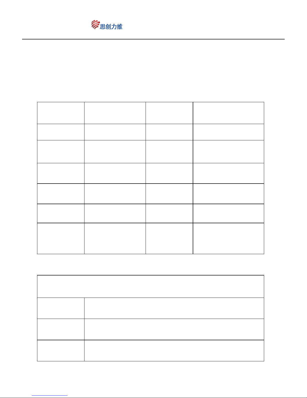
Main Functions Fast Call Up
Fast Call Up
FUNCTION Fast Call Up
FUNCTION
Call 81 Auto IR Call 95 Open OSD Menu
Call 82 Turn on IR Call 99
355°Horizontal
scanning
Call 83 Turn off IR Call 105
RATIO SPEED :
ON and OFF
Call 106
clear all Settings to
restore the default
Call 107
Horizontal start
position fix
Set 125 Set Home position Call 125 Clear Home position
Call 126
increase 1 minute for
Home position
( Max 10 minutes )
Call 127
decrease 1 minute for
Home position
( Min. 1 minute )
RUN tour
Fast Call Up
FUNCTION
Call 96 Run tour 3 ( 16~30 preset )
Call 97 Run tour 2 ( 6~15 preset )
Page 14
www.ctronicssecuritycameras.com
14
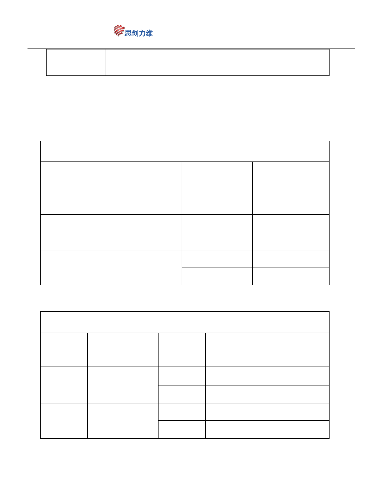
Call 98 Run tour 1 ( 1~5 preset )
RUN A-B scan
Fast Call Up FUNCTION Fast Call Up FUNCTION
Call 91 A-B scan 1
Set 83 Left limit 1
Set 84 Right limit 1
Call 92 A-B scan 2
Set 85 Left limit 2
Set 86 Right limit 2
Call 93 A-B scan 3
Set 87 Left limit 3
Set 88 Right limit 3
RUN pattern scan
Fast Call
Up
FUNCTION
Fast Call
Up
FUNCTION
Call 108 Run pattern scan 1
Call 113 start recording scanning track 1
Call 114 end of recording scanning track 1
Call 109 Run pattern scan 2
Call 115 start recording scanning track 2
Call 116 end of recording scanning track 2
Page 15
www.ctronicssecuritycameras.com
15
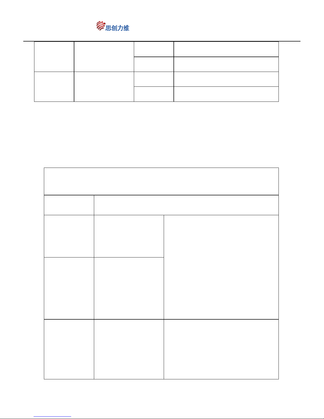
Call 110 Run pattern scan 3
Call 117 start recording scanning track 3
Call 118 end of recording scanning track 3
Call 111 Run pattern scan 4
Call 121 start recording scanning track 4
Call 122 end of recording scanning track 4
Former control status
Fast Call Up
FUNCTION
Call 130
Release PTZ camera
movement lock
Before calling cruise, limiting the
scan, 355 degree panorama, call 131
preset point could lock PTZ camera
movement. After lock PTZ camera
movement, PTZ camera will back to
the former controlled status when user
stop control PTZ camera. Call 130
preset point could release the lock.
Call 131
Lock PTZ camera
movement
Call 132
Increase the time of
recovering control
Under PTZ camera movement, it
allows user to make some
non-functionality operation. After user
finish operation, PTZ camera will
recover to the former controlled
Page 16
www.ctronicssecuritycameras.com
16
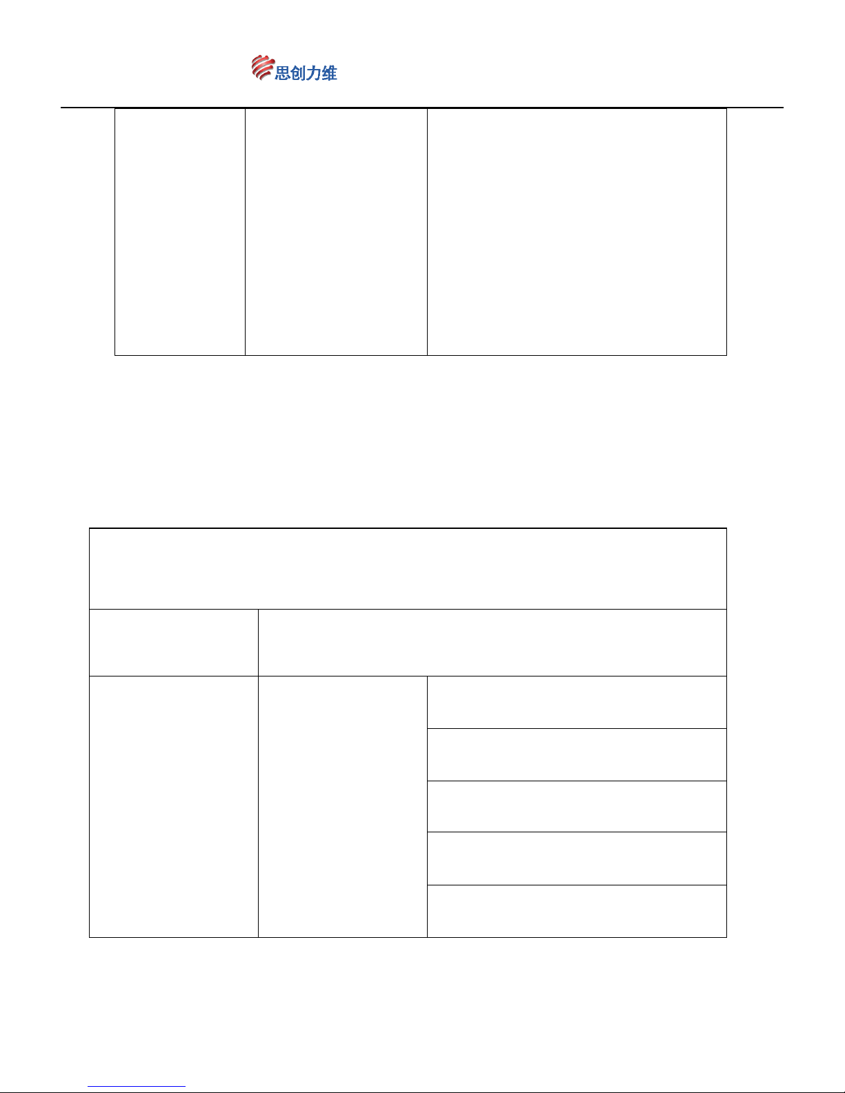
Call 133
Decrease the time of
recovering control
status. The default recover time is 5
minutes. User can increase the time
by calling 132 preset point. Each
calling operation increase 1 minute.
Calling 133 preset point to decrease
the recover time. Each calling
operation decrease 1 minute. Max 10
minutes, and minimum 1 minute.
SPECIAL FUNCTION
Fast Call Up
FUNCTION
Call 103
Open
Camera Menu
ZOOM+ : UP
ZOOM- : DOWN
FOUCS Near : Left
FOUCS Far : Right
Iris : Enter
Page 17
www.ctronicssecuritycameras.com
17
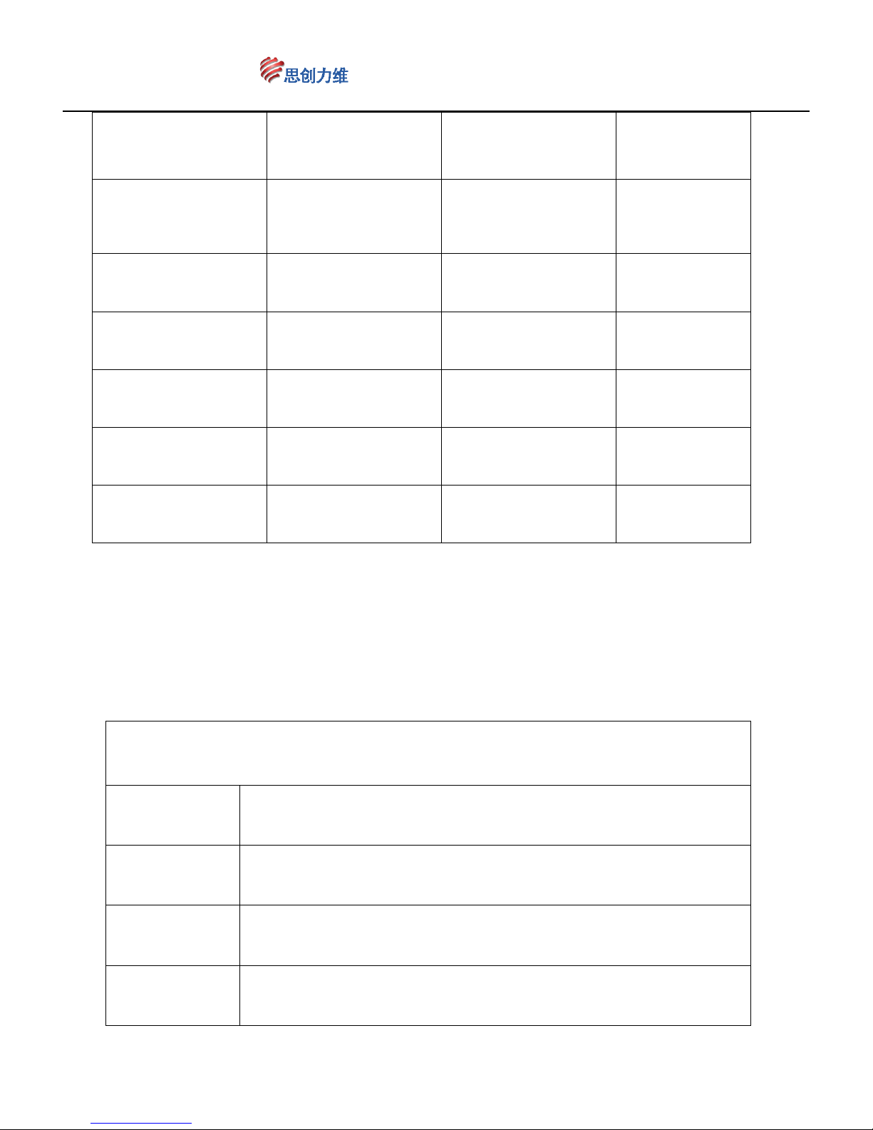
Fast Call Up
FUNCTION Fast Call Up FUNCTION
SET 254 PRESET,
Call 1
ZOOM OSD ON
SET 254 PRESET,
Call 17
HLC OFF
SET 254 PRESET,
Call 2
ZOOM OSD OFF
SET 254 PRESET ,
Call 18
HLC level 1
SET 254 PRESET,
Call 3
Through fog OFF
SET 254 PRESET ,
Call 19
HLC level 2
SET 254 PRESET,
Call 4
Through fog level 1
SET 254 PRESET ,
Call 20
HLC level 3
SET 254 PRESET,
Call 5
Through fog level 2
SET 254 PRESET ,
Call 21
IN DOOR
SET 254 PRESET,
Call 6
Through fog level 3
SET 254 PRESET ,
Call 22
OUT DOOR
More special
preset
function form
RUN tour
Fast Call Up
FUNCTION
Call 181 Run tour 1 ( 1~5 preset )
Call 182 Run tour 2 ( 6~15 preset )
Call 183 Run tour 3 ( 16~30 preset )
Page 18
www.ctronicssecuritycameras.com
18
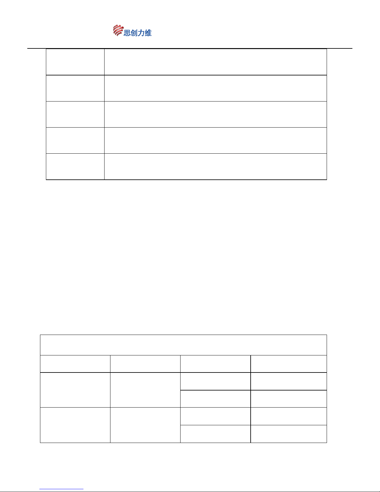
Call 184 Run tour 4 ( 31~50 preset )
Call 185 Run tour 5 ( 1~30 preset )
Call 186 Run tour 6 ( 1~40 preset )
Call 187 Run tour 7( 1~60 preset )
Call 188 Run tour 8 ( 1~80 preset )
RUN A-B scan
Fast Call Up FUNCTION Fast Call Up FUNCTION
Call 141 A-B scan 1
Set 81 Left limit 1
Set 82 Right limit 1
Call 142 A-B scan 2
Set 83 Left limit 2
Set 84 Right limit 2
Page 19
www.ctronicssecuritycameras.com
19
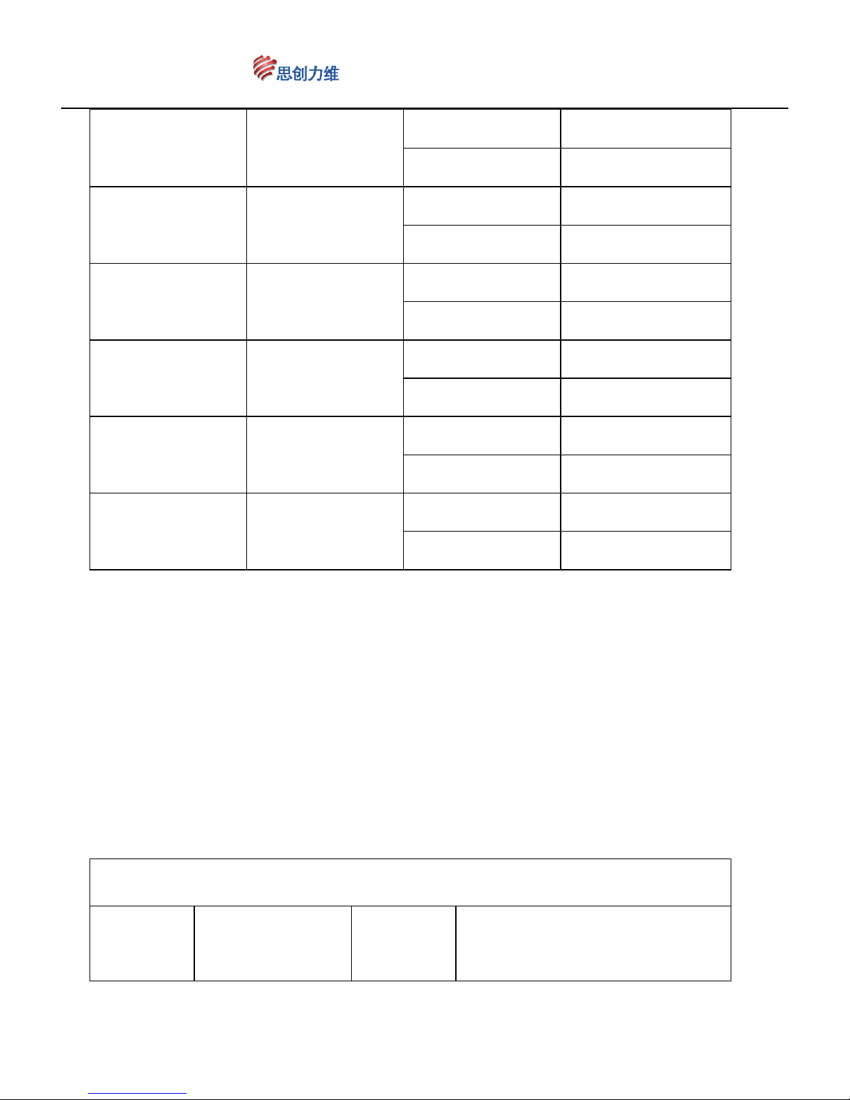
Call 143 A-B scan 3
Set 85 Left limit 3
Set 86 Right limit 3
Call 144 A-B scan 4
Set 87 Left limit 4
Set 88 Right limit 4
Call 145 A-B scan 5
Set 89 Left limit 5
Set 90 Right limit 5
Call 146 A-B scan 6
Set 91 Left limit 6
Set 92 Right limit 6
Call 147 A-B scan 7
Set 93 Left limit 7
Set 94 Right limit 7
Call 148 A-B scan 8
Set 95 Left limit 8
Set 96 Right limit 8
RUN pattern scan
Fast Call
Up
FUNCTION
Fast Call
Up
FUNCTION
Page 20
www.ctronicssecuritycameras.com
20
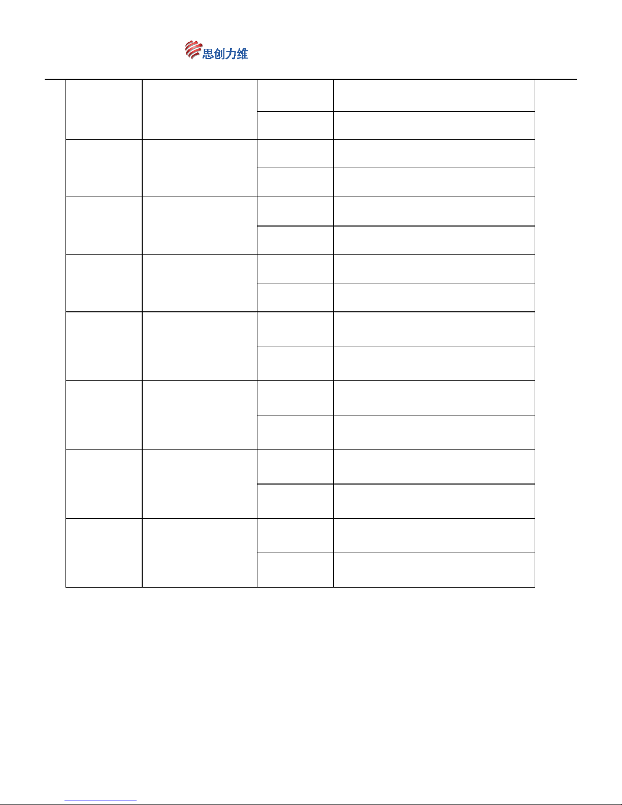
Call 151 Run pattern scan 1
Call 159 start recording scanning track 1
Call 160 end of recording scanning track 1
Call 152 Run pattern scan 2
Call 161 start recording scanning track 2
Call 162 end of recording scanning track 2
Call 153 Run pattern scan 3
Call 163 start recording scanning track 3
Call 164 end of recording scanning track 3
Call 154 Run pattern scan 4
Call 165 start recording scanning track 4
Call 166 end of recording scanning track 4
Call 155 Run pattern scan 5
Call 167 start recording scanning track 5
Call 168 end of recording scanning track 5
Call 156 Run pattern scan 6
Call 169 start recording scanning track 6
Call 170 end of recording scanning track 6
Call 157 Run pattern scan 7
Call 171 start recording scanning track 7
Call 172 end of recording scanning track 7
Call 158 Run pattern scan 8
Call 173 start recording scanning track 8
Call 174 end of recording scanning track 8
Ⅶ、Notice
Page 21

www.ctronicssecuritycameras.com
21
1、The power supply of this product should be DC12V-14V, please use matched
power from our company to supply;
2、Forbid turning around by outside force whether power on or off
3、Dial switch is on the bottom of the ball cover. Open buckle, you can adjust the
address code and baud rate. Please don’t open without permission
4、In order to ensure the precision of preset position, please set left and right limit
position before setting preset position. Make sure the preset position in limit
range;
5、If the preset position come to off normal after long time of auto tour, power off
or outside force, by “calling 107 preset position ”command to reset the dome to
normal state;
6、In order to control the infrared light calorific value effectively and ordinary
infrared machine “flashlight” phenomenon independent control, switch the lens
at 11 times, so if there is one set of lamp off, are all normal phenomenon.
Because the IR light off means they are under a state of rest when the
irradiation angle and the current camera viewing angle are not consistent.
7、The preset setting of this camera with lens preset position as the same as
ordinary high-speed dome camera. As for setup method, please refer to “preset
position settings”
8、The camera outlet is directly high temperature conductive ring lines avoid
interface, please don’t pull output cable.
Page 22
www.ctronicssecuritycameras.com
22
Ⅸ、Simple sheet for check faults
Faults Possible reasons Solution
Power on, but
no action, no
image,
Indicator light
off.
Power wires connected wrong Correct
Power damaged Change
Power is not right Change
Power wires are poor connection Rule out
Power on,
camera can
check itself and
display the
image, but you
can't control it
Address codes, baud rate are wrong
Reset the address
codes and baud rate
Wrong protocol Correct
RS485 wires connected wrong or
damaged
Check RS485 wires
connection
Self-check is
abnormal,
have image but
with electrical
motor working
voice
Machine faults repair
Camera is crooked
Move and adjust its
position
Power is not enough Change the power
Image is
unstable
Video wires are poor connection Rule out
Power is not enough Change the power
Video route is bearing interruption Rule out
Bad controlling Power is not enough
Change power, you'd
better put the power
near to the camera
Page 23
www.ctronicssecuritycameras.com
23
Check the farthest camera's
controlling
resistance, see if it added into
Add the resistance
The distance is too long, 485 signal
are cut down
Change transverter
Dome Performance index
material Shell aluminium alloy
Shell Index
Size 4",thickness 1.8mm
Color white
Manual
operation
speed
Horizontal
rotation range
355°Unlimited
Vertical rotation
range
0°~ 90°,180°Automatic turning
function
Running speed
level:0.1°- 40°/sec, vertical:0.1°-
40°/sec
The preset
position
moving speed
Running speed level:40°/sec;vertical:40°/sec
Electric index
input voltage DC12V
interiorinput
power
36W
Infrared lamp
irradiation
distance
80 meters
functional
parameter
Communication RS-485
preset 80
cruise track 8
PTZ control
protocol
Automatic recognition PELCO-P or
PELCO-D
Working
temperature
Indoor type
0℃~60℃ Intermittent operation;
0℃~50℃ Continuous operation
Page 24
www.ctronicssecuritycameras.com
24
Outdoor type
max: 0℃ ~60℃ Intermittent
operation; 0℃~50℃ Continuous
operation
minimum:-50°C~0℃ Intermittent
operation;-25℃~0℃ Continuous
operation
weight 1.2 kg
Note: The products bring forth the new through the old, parameters such as
update, without prior notice.
Page 25
www.ctronicssecuritycameras.com
25
Drahtlose WIFI Hotpoint Mini Dome
Kamera
Kamera mit Schrittmotor
Bedienungsanleitung
CTIPC-260CWS
Page 26

www.ctronicssecuritycameras.com
26
Bitt lesen Sie die Installationsanweisungen bevor Sie die Kamera verwenden.
Ⅰ:Gebrauchsanweisung
Danke, dass Sie unsere INTELLIGENTE SPEED DOME KAMERA verwenden.
Entsprechend unserer Garantiebestimmungen, reparieren oder ersetzen wir Teile, die
im Zuge einer normalen Nutzung schadhaft werden, innerhalb der Gewährleistungsfrist.
Benutzer dürfen ohne unsere Zustimmung innerhalb der Gewährleistungsfrist keine
Veränderungen oder Reparaturen an dem Produkt durchführen. Während der
Gewährleistungsperiode werden wir ohne zusätzliche Kosten Teile reparieren oder
ersetzen die unter normalen Nutzungsbedingungen schadhaft wurden. Davon
ausgenommen sind die Montagehalterung sowie Kabel und das Gehäuse. Die
Entscheidung, ob es sich um einen Garantiefall handelt obliegt uns.
Keine kostenlose Reparatur oder Austausch wird gewährt wenn:
6、 Das Produkt unautorisiert repariert oder zerlegt wurde;
7、 Schäden durch den Transport oder den Versand vorliegen;
8、 Schäden verursacht durch den Benutzer wegen nicht den Anweisungen
entsprechender Verwendung oder Wartung, Dampf, Untertauchen, Sturz,
Korrosion oder andere vom Benutzer herbeigeführte Schäden ;
9、 Fehlfunktionen die durch eine Überbelastung der Umgebung hervorgerufen
werden;
10、 Schäden die durch höhere Gewalt hervorgerufen werden;
Vorschlag:Um die volle Funktionalität zu gewährleisten, muss vor der Verwendung mit
einem Produkt eines Drittanbieters ein Kompatibilitätstest durchgeführt
werden.
Ⅱ、Produkteigenschaften
Elegantes Aussehen mit 4" Gehäuse in dem die Kameralinse drehbar
untergebracht ist. Die IR-Leuchte ist nicht durch die Abdeckung versteckt. Für
die Anwendung der Adress-Codes und die Einstellung der Baud Rate ist ein
Öffnen des Gehäuses nicht notwendig.
Die Kameralinse wird durch Lager und Riemen bewegt und hat daher sanftere
Bewegungsabläufe und eine lange Lebensdauer.
Page 27

www.ctronicssecuritycameras.com
27
Durch den Riemenantrieb ist die Bewegung stabiler, zuverlässiger und leiser.
Reaktionsfähiger Schrittmotor für genaue Positionierung.
Superhelles IR LED Array für effektive Nachtsicht auf Entfernungen bis 80m.
Adaptives Steuerungsprotokoll, adaptive Kommunikations-Baudrate und
dadurch erleichterte Benutzung ohne kompliziertes Setup.
Verschiedene Winkel des Infrarot-Lichts passend zu den schnell wechselbaren
Blickwinkeln der Kameralinse. Wenn der Kamerawinkel geändert wird, kann es
bei starren IR-LED Leuchten zu einem ‚Taschenlampen-Effekt‘ kommen, wobei
es zu einer Spiegelung in der Linse kommt. Dies wird bei dieser Kamera
vermieden. Zudem wird durch die intermittierende Beleuchtung die
Stromaufnahme reduziert. Das verbessert die Lebensdauer der Kamera.
Die Decoder Platine versorgt den Motor, die Kamera und die IR LED
separat mit Strom wodurch die Kamera stabiler arbeiten kann.
Durch einen Kontakt-Ring wird das Verwickeln der Drähte vermieden und
eine kontinuierliche Drehung um 355° ermöglicht.
80 voreingestellte Positionen; 8 Bewegungsrouten, 1 feste
Überwachungsposition, die Pausenzeit kann für jede Position in 5
Sekunden-Schritten 5/10/15/…/55/60 Sekunden eingestellt werden, es können
Begrenzungspositionen links und rechts eingestellt werden, Speicherdaten
gehen auch nach dem Ausschalten nicht verloren.
Einstellgeschwindigkeit: horizontal 355° Verstellung 0,1°-40° / Sekunde;
vertikal 0~90° Verstellung 0,1°-40° / Sekunde
Ⅲ:Technische Daten
1、Stromversorgung
Stromzufuhr: DC12V—3000mA
PTZ Motor: DC12V—500mA
IR Beleuchtung: DC12V—1800mA
Linse: DC12V—200mA
Kamera Versorgung: DC12V—200mA
Page 28

www.ctronicssecuritycameras.com
28
andere: DC12V—300mA
Nachrüstbares Temperaturregelgerät
Arbeitstemperatur: -25°C~+55°C
Adressbereich: 1~255
Kommunikation Modus: RS485
Protokoll:unterstützt verschiedene Protokolle
Baudrate: 2400bps、4800bps、9600bps、19200bps Auto
Kontrollequipment: Video Matrix、industrielle Steuerung DVR、DVR、NVR
、
Kontrollkeyboard, etc.
Voreinstellung: 255 Voreinstellungen,1-80 für den Dome, die anderen für
Spezialfunktionen
Inspektions-Teams:8 Gruppen
Pause in jeder der voreingestellten Positionen:5*n Sekunden einstellbar (1≤n≤20).
2、
Mechanische Spezifikationen
PTZ Rotationswinkel: horizontal 355° unlimitierte Rotation, vertikal 0°~ 90°
PTZ Rotationsgeschwindigkeit: horizontal
0,1°- 40°/s,
vertikal
0,1°- 40°
/s
Rotationslimit
:
horizontal einstellbar im Bereich von 355°, Software- und
photoelektrische Limitierung.
3、Umgebung
Arbeitstemperatur:
-25°C~+55°C
Temperaturkontrolle: integriert 45°C Umgebungstemperatur.
Luftfeuchtigkeit: 90% RH
Ⅳ:Einrichtung der Verbindung und der Kamera
1、Passende Kameras laut Tabelle 1
:
Tabelle 1:
Passende Geräte
Produkt Installation Montage Strom
Kabel
Page 29
www.ctronicssecuritycameras.com
29
High Speed
Dome
Wand
Wand-
halterung
DC12V
3A
Stromversorgung
Decke
Decken-
halterung
SIZE PHOTO
3、
Für den Anschluss der IP Dome Kamera sehen Sie bitte das Anschlussdiagramm.
,
Ethernet
Page 30
www.ctronicssecuritycameras.com
30
:AddressⅤ e, Protokoll, Baudrate Einstellung
High Speed Dome Kamera mit eingebautem Decoder. Sie können die Adresse, das
Protokoll und die Baudrate einstellen. Sie können für eine einfachere Konfiguration
den 8-Bit-Wählschalter unter dem leicht zu öffnenden Dome-Deckel erreichen, um
dort die Adresse zu wählen.
1、Adresseinstellungen
Nr.1~ Nr.8 werden verwendet um die Adress-Codes in einem Bereich von 1-255
einzustellen. Ab Werk ist 1 eingestellt. Verwenden Sie das binäre System
„ON“ bedeutet 1 und „OFF“ bedeutet 0. Für Details sehen Sie bitte das Blatt 2.
Adresscodes und Wählschalter können nach folgenden Codes konfiguriert werden:
Binär Add
Binär Add
Binär Add
Binär Add
00000000
0 11110000
15 01111000 30 10110100 45
10000000
1 00001000
16 11111000 31 01110100 46
01000000
2 10001000
17 00000100 32 11110100 47
11000000
3 01001000
18 10000100 33 00001100 48
00100000
4 11001000
19 01000100 34 10001100 49
10100000
5 00101000
20 11000100 35 01001100 50
Page 31
www.ctronicssecuritycameras.com
31
01100000
6 10101000
21 00100100 36 11001100 51
11100000
7 01101000
22 10100100 37 00101100 52
00010000
8 11101000
23 01100100 38 10101100 53
10010000
9 00011000
24 11100100 39 01101100 54
01010000
10 10011000
25 00010100 40 11101100 55
11010000
11 01011000
26 10010100 41 00011100 56
00110000
12 11011000
27 01010100 42 10011100 57
10110000
13 00111000
28 11010100 43 01011100 58
01110000
14 10111000
29 00110100 44 11011100 59
2、Baudrate Einstellungen (Die Baudrate ist einstellbar. Dieser Teil ist einfach eine
Referenz für bestehende Produkte)
Die Baudrate kann durch die 4. und 5. Wählschalter eingestellt werden. Es stehen
2400BPS 、 4800BPS 、 9600BPS 、 19200BPS zur Auswahl 。 Das Setzen des
Wählschalters auf "ON" steht für 1, auf "OFF" steht für 0. Die Baudrate und die
zugehörigen Wählschalter entnehmen Sie bitte dem Blatt 3.
Blatt 3:Baudrate und Wählschalter Diagramm
Wählschalter
2400 bps 4800 bps 9600 bps 19200 bps
Nr.4
OFF ON OFF ON
Nr.5
OFF OFF ON ON
3、Protokoll Einstellungen
Der Decoder der Speed Dome Kamera wird das Protokoll automatisch anpassen,
Sie müssen keine Einstellungen vornehmen. Unterstützt werden PELCO_D und
PELCO_P
Ⅵ:Einstellungen der Funktionen
1、Set / Call Voreinstellungen vornehmen
Voreingestellte Funktionen können durch Kontrollgeräte, Tastaturen und andere
Page 32

www.ctronicssecuritycameras.com
32
Geräte gesteuert werden. Durch Call und Set Befehle können Parameter und
horizontaler sowie vertikaler Betrachtungswinkel der Kamera gewählt werden indem sie
in digitaler Form in der IR Kamera gespeichert werden. Diese Kamera unterstützt 255
Voreinstellungen.
(1)Position einstellen
Bewegen Sie Ihre IR Dome Kamera indem Sie sie eine Tastatur, den DVR oder ein
anderes Steuergerät verwenden. Sie können die Voreinstellungen verändern indem Sie
sich auf Voreinstellungs-Funktionen zur Steuerung beziehen. Über die Zoomtasten
können Sie das Objektiv einstellen, und geben Sie die entsprechende Nummer der
voreingestellten Position ein.
Beispiel:Verwenden Sie ein Steuergerät um die voreingestellte Nr. 1 einzustellen.
a、Drücken Sie den Knopf “set preset”,dann bewegen Sie die Kamera über den Joystick
zu der gewünschten Position. Bewegen Sie die Linse schrittweise zu dem gewünschten
Winkel durch das Drücken der “zoom”-Taste
b、 Geben Sie “1” ein
c 、Drücken Sie die “enter”-Taste
(2)Voreinstellung aufrufen (call)
Beziehen Sie sich auf die Voreinstellungsfunktionen, die Sie über ein Keyboard oder ein
DVR aufrufen können, um zu den voreingestellten Positionen zu gelangen.
Beispiel:Verwenden Sie ein Steuergerät um die voreingestellte Nr. 1 einzustellen.
a、Drücken Sie “ call preset position”, und geben Sie “1” ein
b、Drücken Sie ‘Enter’
2、
Automatische Kamerabewegung aufrufen / löschen
Auto-Tour ist eine Funktion, die die Kamerabewegung nach einem zufälligen Muster
ausführt. Ein externer Befehl kann die Dome-Kamera nach vorgegebenen Routen
bewegen. Es stehen 8 verschiedenen Routen zur Verfügung. Jede der Routen kann
zwischen 5 und 30 Stopps speichern.
(1)Autoroute aufrufen (call)
Page 33
www.ctronicssecuritycameras.com
33
Über ein Keyboard oder einen DVR können Sie das Kommando „call No.98“ eingeben,
um die Voreinstellung abzurufen. Durch dieses Kommando wird die Dome Kamera in
den Auto-Route Modus versetzt und fährt dabei die Positionen ab die in “call No.97
preset position” als Auto-Tour festgelegt wurden. Für die korrespondierenden
voreingestellten Positionen von 3 Bewegungsrouten sehen Sie bitte in der Tabelle 5
nach.
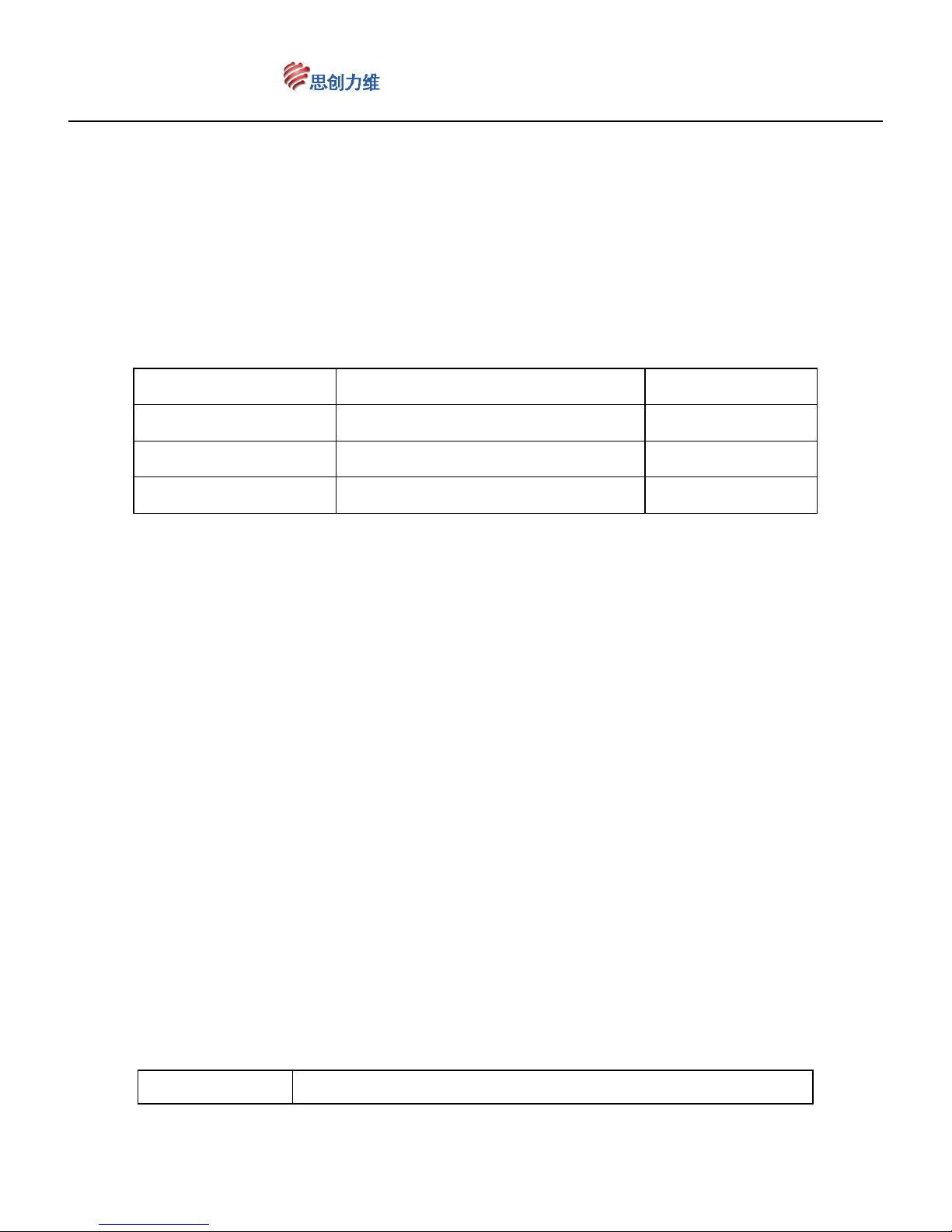
Tabelle 5:voreingestellte Positionen der Route
Route Eingabe Enthält Position
1. Route
Voreinstellung Nr.98
1~5 Position
2. Route Voreinstellung Nr.97
6~15 Position
3. Route Voreinstellung Nr.96
16~35 Position
Hinweis: Die voreingestellte Anzahl an Positionen ist wie in der Tabelle
angegeben, Sie können aber bis zu 30 Positionen speichern.
Beispiel:Verwenden Sie ein Steuergerät um die voreingestellte Nr. 1 einzustellen.
a、Drücken Sie den Knopf “call preset position”, und geben Sie “97” ein
b、Drücken Sie “Enter”
(2)Wartezeit an den voreingestellten Positionen während der Auto-Tour
Sie können die Wartezeit an den voreingestellten Positionen zwischen 5 und 60
Sekunden einstellen wenn die IR Dome Kamera im Auto-Tour Modus ist. Verwenden
Sie dazu ein Control Keyboard oder ein DVR um das Kommando “call No.123 preset
position” zu senden, um die Wartezeit um 5 Sekunden zu erhöhen und “call No.124
preset position”, um die Wartezeit um 5 Sekunden zu verringern. Wartezeiten
können mit den Kommandos aus Tabelle 6 eingestellt werden.
Tabelle 6: Wartezeiten Tabelle
Wartezeit Eingabe
Page 34
www.ctronicssecuritycameras.com
34
Standard 10s
Call Nr.106 auf Voreinstellung zurücksetzen
+ 5s Voreinstellung Nr.123
- 5s Voreinstellung Nr.124
Beispiel: Verwenden Sie ein Steuergerät um die Wartezeiten in 5s-Schritten
einzustellen
a、Drücken Sie “call preset position”, und geben Sie “123” ein
b、Drücken Sie “ enter”
Hinweis:Wenn die Position der Kamera nach langer Zeit im Auto-Tour-Modus
oder durch Krafteinwirkung nicht korrekt ist, schalten Sie die Kamera aus und
starten Sie sie neu.
(3)Bewegungsrouten löschen
Call Nr.106 um alle Einstellung auf Werkszustand zurück zu setzen.
3、Bewegungslimits nach links und rechts scannen、355° horizontal scannen、Muster
scannen.
Sie können über ein Kontrollkeyboard oder ein DVR Kommandos ausführen. Sie
können Limits, horizontale und Musterscanns lesen oder speichern.
(1)Limit Scann für links und rechts
Geben Sie über ein Keyboard oder ein DVR “set Nr.83 preset position” nachdem Sie
die Kamera zur rechten Position bewegt, und “set Nr.84 preset position” nachdem Sie
die Kamera zur linken Position bewegt haben. Damit sind die Limits gesetzt.
Nun bewegt sich die Dome Kamera nur noch zwischen den beiden Positionen.
Tipp: Setzen Sie die Limits für die rechte und linke Position entsprechend den
Beziehungen entsprechend der Tabelle 7.
Beispiel: Verwenden Sie ein Steuergerät um die Limits einzustellen.
d、 Drücken Sie “set preset”, dann bewegen Sie die Kamera zur gewünschten
Position durch Drücken des Joysticks.
e、 Geben Sie “83” ein
f、 Drücken Sie die “enter” Taste
d、Bewegen Sie die Kamera zur linken Limit-Position
e、Geben Sie “84” ein
f、Drücken Sie die “ enter”-Taste
Page 35
www.ctronicssecuritycameras.com
35
(2)Aufrufen der Limits
Verwenden Sie ein Keyboard oder ein DVR um das Kommando “call No.91 preset
position” aufzurufen und einen Limit-Scann durchzuführen. Die anderen
Limit-Scans werden in der Tabelle 7 dargestellt.
Tabelle 7:Limit Scan Voreinstellungen
Limit Scan einstellen abrufen
1. Scan
Limit links:set Nr.83 Speicher
Limit rechts:set Nr.84 Speicher
Call Nr.91
Speicher
2. Scan
Limit links:set Nr.85 Speicher
Limit rechts:set Nr.86 Speicher
Call Nr.92
Speicher
3. Scan
Limit links:set Nr.87 Speicher
Limit rechts:set Nr.88 Speicher
Call Nr.93
Speicher
(3)355° Horizontaler Scan
Verwenden Sie ein Keyboard oder ein DVR um das Kommando “call No.99 preset
position” wonach die Dome Kamera mit dem 355° Horizontal-Scan startet.
(4)Muster Scan
Dieses Produkt hat 4 gespeicherte Gruppen von Muster Scans. Die Muster
sorgen für eine Bewegung zwischen zwei Punkten.
Die Start- und Endpunkte für die Pattern-Scans sind in der Tabelle 8 angeführt.
Beispiel:Verwenden Sie ein Keyboard oder ein DVR um die Scanns zu starten
oder zu speichern.
a、Legen Sie einen Startpunkt fest: Bewegen Sie die Kamera mittels Joystick zur
gewünschten Startposition und geben Sie dann Nr.113 ein, um den Startpunkt für
den Muster-Scan festzulegen.
b、Bewegen Sie die Kamera mit dem Joystick auf die nächste Zielposition
c、speichern Sie den Endpunkt: Bewegen Sie die Dome Kamera mit dem Joystick zur
Endposition und speichern Sie die Position durch Eingabe der Nr.114.
Nun ist der Muster-Scan komplett.
Page 36
www.ctronicssecuritycameras.com
36
d、Durch den Aufruf der Nr.108 wird der erste Muster-Scan aufgerufen.
Tabelle 8:Muster-Scan
Muster Speicherkommmandos Aufrufe
1. Muster
Startpunkt:Eingabe Nr.113
Endpunkt:Eingabe Nr.114
call Nr.108
Voreinstellung
2. Muster
Startpunkt:Eingabe Nr.115
Endpunkt:Eingabe Nr.116
call Nr.109
Voreinstellung
3. Muster
Startpunkt:Eingabe Nr.117
Endpunkt:Eingabe Nr.118
call Nr.110
Voreinstellung
4. Muster
Startpunkt:Eingabe Nr.119
Endpunkt:Eingabe Nr.120
call Nr.111
Voreinstellung
(4)Limit Scan、355° Horizontaler Scan、Muster-Scan löschen
Call Nr.106 löscht alle Einstellungen und setzt Sie auf Werkseinstellung。
4、Auf Werkseinstellung zurücksetzen
Rufen Sie Nr.106 um auf Werkseinstellungen zurückzustellen.
Hauptfunktionen aufrufen
Aufruf Nr. FUNKTION Aufruf Nr. FUNKTION
Call 81 IR automatisch Call 95 OSD Menü öffnen
Call 82 IR einschalten Call 99
355° Horizontaler
Scan
Call 83 IR ausschalten Call 105
RATIO SPEED :
ON und OFF
Call 106
Zurücksetzen auf
Werkseinstellungen
Call 107
Horizontale
Startposition setzen
Call 125
Home Position
setzen
Call 125 Home-Position löschen
Page 37
www.ctronicssecuritycameras.com
37
Call 126
1 Minute auf
Home-Position
addieren
( Max. 10 Minuten )
Call 127
Home Position um 1
Minute reduzieren
( Min. 1 Minute )
Tour ausführen
Aufruf Nr.
FUNKTION
Call 96 Tour 3 ( 16~30 Positionen )
Call 97 Tour 2 ( 6~15 Positionen )
Call 98 Tour 1 ( 1~5 Positionen )
A-B Scan ausführen
Aufruf Nr. FUNKTION Aufruf Nr. FUNKTION
Call 91 A-B Scan 1
Set 83 Linkes Limit 1
Set 84 Rechtes Limit 1
Call 92 A-B Scan 2
Set 85 Linkes Limit 2
Set 86 Rechtes Limit 2
Call 93
A-B Scan 3
Set 87 Linkes Limit 3
Page 38
www.ctronicssecuritycameras.com
38
Set 88 Rechtes Limit 3
Muster Scan ausführen
Aufruf Nr.
FUNKTION Aufruf Nr.
FUNKTION
Call 108
Muster Scan 1
ausführen
Call 113 Startpunkt für Muster-Scan 1
Call 114 Endpunkt für Muster-Scan 1
Call 109
Muster Scan 2
ausführen
Call 115 Startpunkt für Muster-Scan 2
Call 116 Endpunkt für Muster-Scan 2
Call 110
Muster Scan 3
ausführen
Call 117 Startpunkt für Muster-Scan 3
Call 118 Endpunkt für Muster-Scan 3
Call 111
Muster Scan 4
ausführen
Call 121 Startpunkt für Muster-Scan 4
Call 122 Endpunkt für Muster-Scan 4
Kontrollstatus
Aufruf Nr. FUNKTION
Page 39
www.ctronicssecuritycameras.com
39
Call 130
PTZ Kamera
Bewegungssperre
aufheben
Der Aufruf von 131 sperrt die
Bewegung der PTZ Kamera des 355°
Panoramas. Durch 130 können Sie
die Sperre wieder aufheben und zum
vorhergehenden Status zurückkehren.
Call 131
PTZ Kamera
Bewegungssperre
setzen
Call 132
Zeit erhöhen für die
Wiederherstellung der
Kontrollfunktion
Während der Kamerabewegung
können nichtfunktionale Operationen
durchgeführt werden. Nachdem Sie
die Funktionen ausgeführt haben wird
die Kamera in den vorherigen Zustand
zurückkehren. Die
Standardeinstellung ist 5 Minuten.
Nach dieser Zeit kehrt die Kamera
automatisch in den Ausgangszustand
zurück. Sie können die Zeit jeweils um
eine Minute durch 132 erhöhen und
durch 133 verringern. Der Wert darf
zwischen 1 und 10 Minuten liegen.
Call 133
Zeit verringern für die
Wiederherstellung der
Kontrollfunktion
Page 40
www.ctronicssecuritycameras.com
40
SPEZIALFUNKTIONEN
Aufruf Nr.
FUNKTION
Call 103 Kameramenü öffnen
ZOOM+ :VERGRÖSSERN
ZOOM- : VERKLEINERN
FOUKS Nahe : Links
FOUKS Fern : Rechts
Iris : Enter
Aufruf Nr.
FUNKTION Aufruf Nr. FUNKTION
SET 254 PRESET,
Call 1
ZOOM OSD EIN
SET 254 PRESET,
Call 17
HLC OFF
SET 254 PRESET,
Call 2
ZOOM OSD AUS
SET 254 PRESET ,
Call 18
HLC Level 1
SET 254 PRESET,
Call 3
Nebelsicht EIN
SET 254 PRESET ,
Call 19
HLC Level 2
SET 254 PRESET,
Call 4
Nebelsicht Level 1
SET 254 PRESET ,
Call 20
HLC Level 3
SET 254 PRESET,
Call 5
Nebelsicht Level 2
SET 254 PRESET ,
Call 21
IN DOOR
SET 254 PRESET,
Call 6
Nebelsicht Level 3
SET 254 PRESET ,
Call 22
OUT DOOR
Page 41
www.ctronicssecuritycameras.com
41
Zusätzliche Funktionen
Tour Bewegung
Aufruf Nr.
FUNKTION
Call 181 Tour 1 ( 1~5 Positionen )
Call 182 Tour 2 ( 6~15 Positionen)
Call 183 Tour 3 ( 16~30 Positionen)
Call 184 Tour 4 ( 31~50 Positionen)
Call 185 Tour 5 ( 1~30 Positionen)
Call 186 Tour 6 ( 1~40 Positionen)
Call 187 Tour 7( 1~60 Positionen)
Call 188 Tour 8 ( 1~80 Positionen)
Page 42
www.ctronicssecuritycameras.com
42
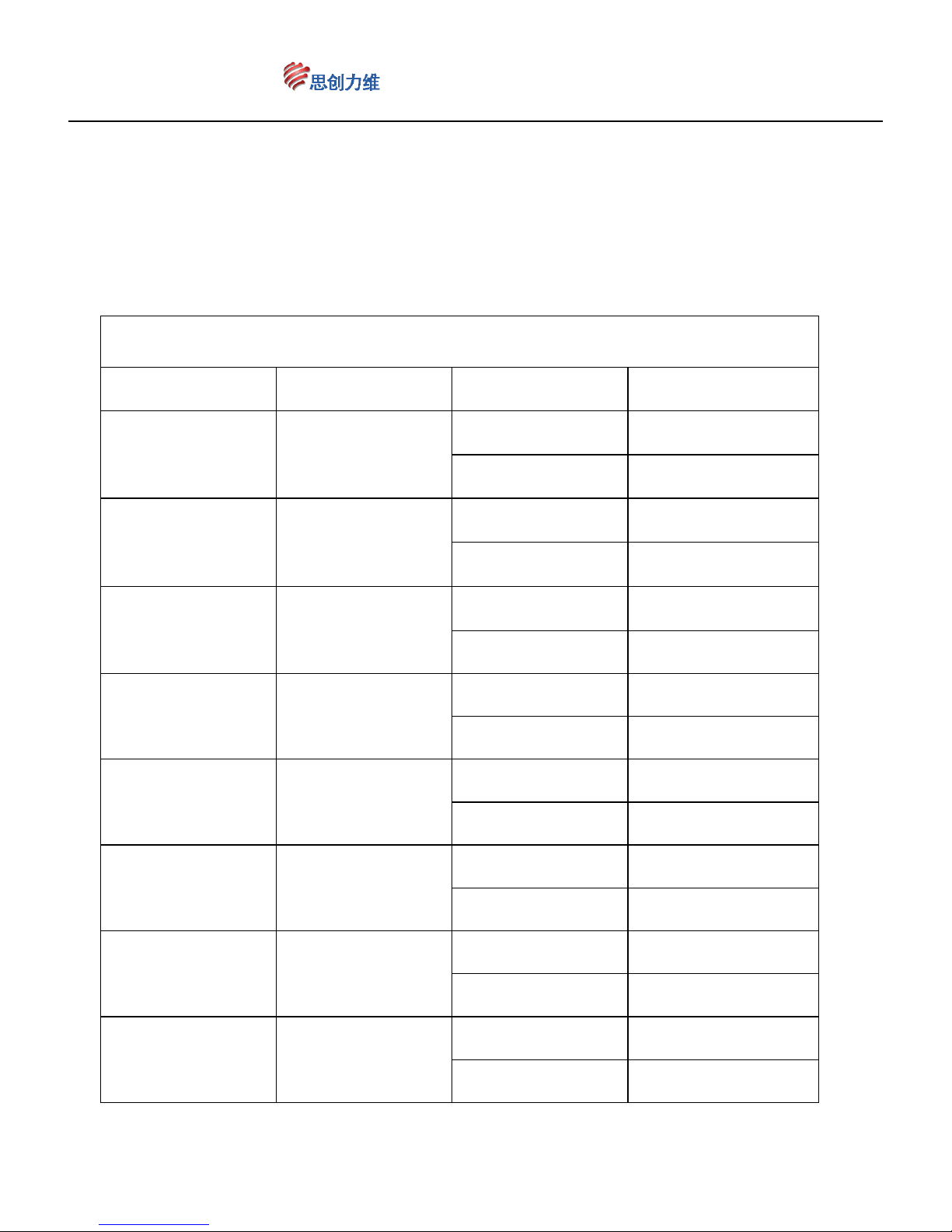
A-B Scan ausführen
Aufruf Nr. FUNKTION Aufruf Nr. FUNKTION
Call 141 A-B Scan 1
Set 81 Limit 1 links setzen
Set 82 Limit 1 rechts setzen
Call 142 A-B Scan 2
Set 83 Limit 2 links setzen
Set 84 Limit 2 rechts setzen
Call 143 A-B Scan 3
Set 85 Limit 3 links setzen
Set 86 Limit 3 rechts setzen
Call 144 A-B Scan 4
Set 87 Limit 4 links setzen
Set 88 Limit 4 rechts setzen
Call 145 A-B Scan 5
Set 89 Limit 5 links setzen
Set 90 Limit 5 rechts setzen
Call 146 A-B Scan 6
Set 91 Limit 6 links setzen
Set 92 Limit 6 rechts setzen
Call 147 A-B Scan 7
Set 93 Limit 7 links setzen
Set 94 Limit 7 rechts setzen
Call 148 A-B Scan 8
Set 95 Limit 8 links setzen
Set 96 Limit 8 rechts setzen
Page 43
www.ctronicssecuritycameras.com
43
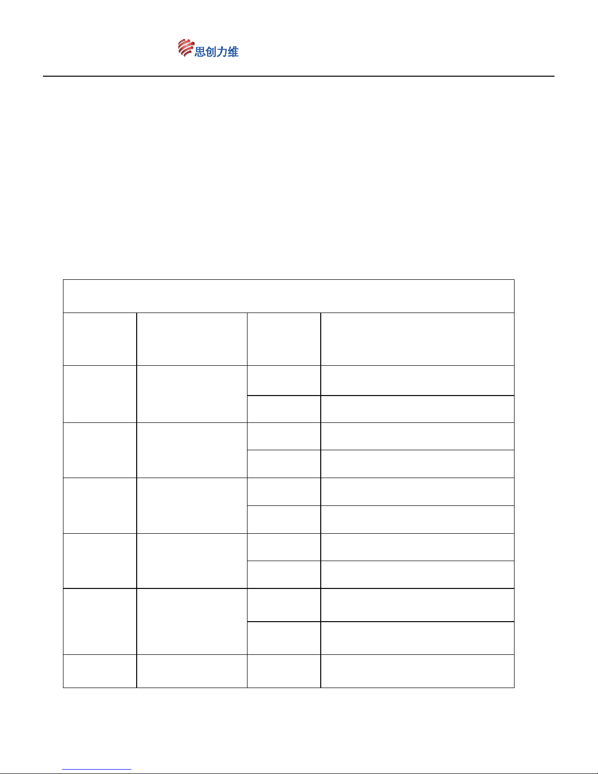
Muster-Scan ausführen
Aufruf
Nr.
FUNKTION
Aufruf
Nr.
FUNKTION
Call 151 Muster-Scan 1
Call 159 Muster-Scan Startposition 1
Call 160 Muster-Scan Endposition 1
Call 152 Muster-Scan 2
Call 161 Muster-Scan Startposition 2
Call 162 Muster-Scan Endposition 2
Call 153 Muster-Scan 3
Call 163 Muster-Scan Startposition 3
Call 164 Muster-Scan Endposition 3
Call 154 Muster-Scan 4
Call 165 Muster-Scan Startposition 4
Call 166 Muster-Scan Endposition 4
Call 155 Muster-Scan 5
Call 167 Muster-Scan Startposition 5
Call 168 Muster-Scan Endposition 5
Call 156 Muster-Scan 6 Call 169 Muster-Scan Startposition 6
Page 44
www.ctronicssecuritycameras.com
44
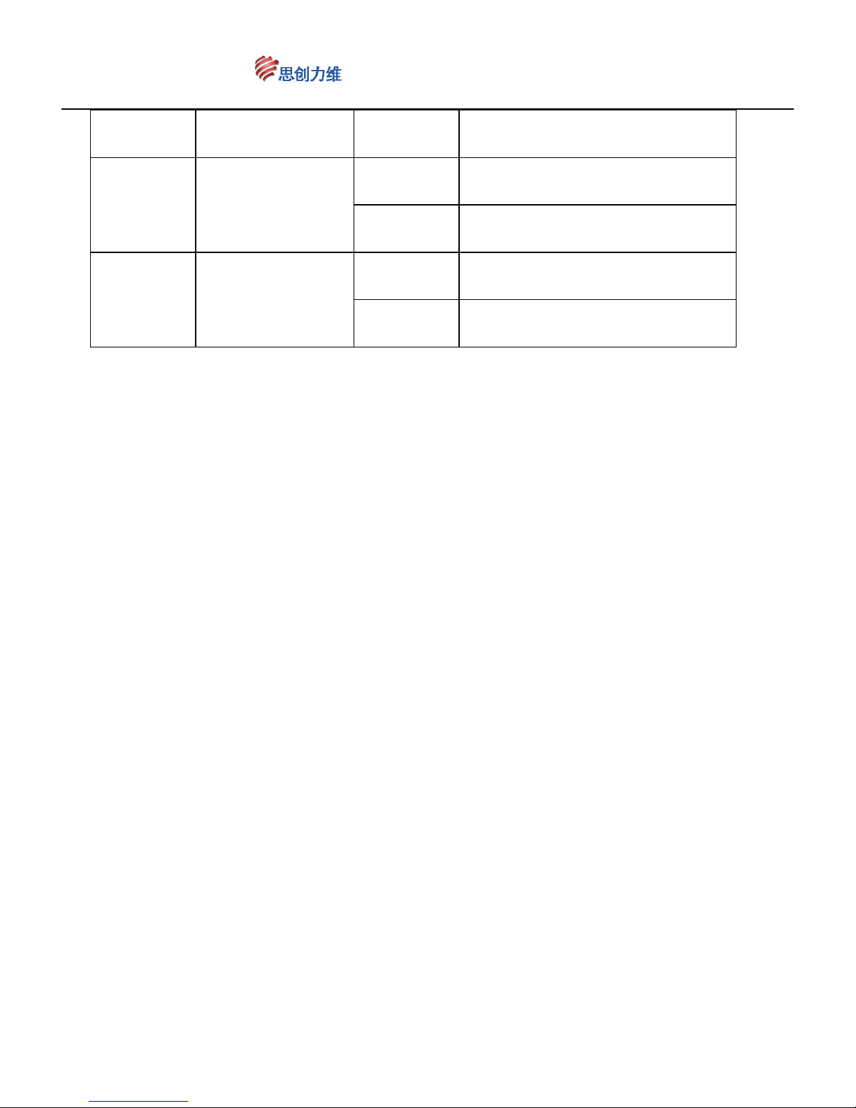
Call 170 Muster-Scan Endposition 6
Call 157 Muster-Scan 7
Call 171 Muster-Scan Startposition 7
Call 172 Muster-Scan Endposition 7
Call 158 Muster-Scan 8
Call 173 Muster-Scan Startposition 8
Call 174 Muster-Scan Endposition 8
Ⅶ、Hinweis
1、Dieses Produkt erfordert eine Stromversorgung mit 12-24V Gleichstrom. Bitte
verwenden Sie ein passendes Netzteil.
2 、 Sichern Sie die Kamera vor Zugriff von außen, damit die Kamera nicht
ausgeschaltet werden kann.
3、Die Dip-Switches befinden sich auf der Unterseite der Dome-Kamera. Öffnen Sie
den Deckel. Sie können den Adresscode und die Baudrate einstellen. Bitte nicht
ohne Erlaubnis öffnen.
4、Um die Präzision der voreingestellten Positionen zu gewährleisten, stellen Sie die
linke und die rechte Endposition ein. So stellen Sie sicher, dass die Bewegung im
Grenzbereich verläuft.
5、Wenn die Position nach langer Nutzung oder durch einen Eingriff von außen
ungenau ist, rufen Sie das Kommando „107“ auf, um die Dome-Kamera auf
einen Normalstatus zurückzubringen.
6 、 Auf Grund der Infrarot-Strahlung kann es zum Taschenlampen-Phänomen
kommen und das Objektiv schaltet sich automatisch um. Das passiert durch die
Page 45
www.ctronicssecuritycameras.com
45
unterschiedlichen Abstrahlwinkel.
7、Die Voreinstellungen dieser Kamera sind gleich mit jenen anderer High Speed
Dome Kameras. Verwenden Sie die Voreinstellungen analog den
Preset-Positionseinstellungen.
8、Die Kamera verwendet einen induktiven Leitungsring statt Kabeln. Bitte ziehen
Sie nicht am Ausgangskabel.
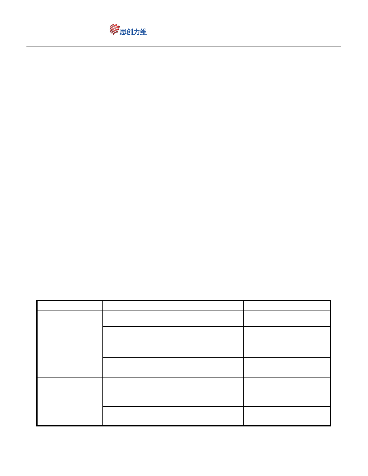
Ⅸ、Einfache Fehlersuche
Fehler Mögliche Gründe Lösung
Eingeschaltet
aber keine Bilde
rund keine
Status LED
Stromzufuhr falsch angeschlossen korrigieren
Stromzufuhr beschädigt korrigieren
Flasche Stromzufuhr korrigieren
Stromkabel haben schlechten
Kontakt
verbessern
Eingeschaltet,
Kamera führ
Selbstcheck
durch, es gibt
Adress-Code, Baudrate
Adress-Code und
Baudrate
zurücksetzen
Falsches Protokoll korrigieren
Page 46
www.ctronicssecuritycameras.com
46
Bilder aber
keine Kontrolle
RS485 Kabel sind falsch
angeschlossen oder kaputt
Prüfen Sie die RS485
Verbindung
Selfcheck ist
abnormal,
Bild ist
vorhanden und
hat
Interferenzen
Motordefekt reparieren
Kameraposition ist falsch
Korrigieren Sie die
Kameraposition
Zu wenig Leistung
Ändern Sie die
Leistung
Bild ist instabil
Videokable hat schlechte Verbindung verbessern
Nicht genug Leistung
Ändern Sie die
Leistung
Motorbewegung unterbricht die
Aufnahme
Motor aus und
checken
Schlechte
Kontrolle
Nicht genug Leistung
Ändern Sie die
Leistung. Netzteil am
besten in der Nähe
Überprüfen Sie den
Leistungswiderstand der am weitest
entfernte Kamera.
Add the resistance
Zu große Entfernung. Das 485 Signal
ist unterbrochen.
Ändern Sie die
Übertragung
Dome Spezifikationen
Material Hülle Aluminium
Hülle Index
Größe 4",Dicke 1,8mm
Farbe white
Geschwindigkeit
Horizontale
Rotation
355° Unlimitiert
Vertikale Rotation
0°~ 90°,180°Automatic Turn
Function
Bewegungsgeschw. horizontal:0,1°- 40°/s
Page 47
www.ctronicssecuritycameras.com
47
vertikal:0,1°- 40°/s
Speicherpunkte
Bewegung
Bewegungsgeschw. horizontal:40°/s;vertikal:40°/s
Spannung
Eingang DC12V
Leistung 36W
Infrarot
Leuchtweite
80 Meter
Funktionale
Parameter
Kommunikation RS-485
Speicherplätze 80
Routen 8
PTZ Protokoll
Automatische Wahl PELCO-P oder
PELCO-D
Arbeitstemperatur
Indoor
0°~60℃ Betrieb unterbrochen;
0℃~50℃ Betrieb ununterbrochen
Outdoor
Max.: 0° ~60° unterbrochener
Betrieb; 0°~50° Dauerbetrieb
min.:-50°C~0° unterbrochener
Betrieb;-25℃~0℃ Dauerbetrieb
Gewicht 1,2 kg
Hinweis: Es können neue Parameter bei einem Produktupdate ohne vorherige
Ankündigung eingeführt werden.
 Loading...