

Page 1
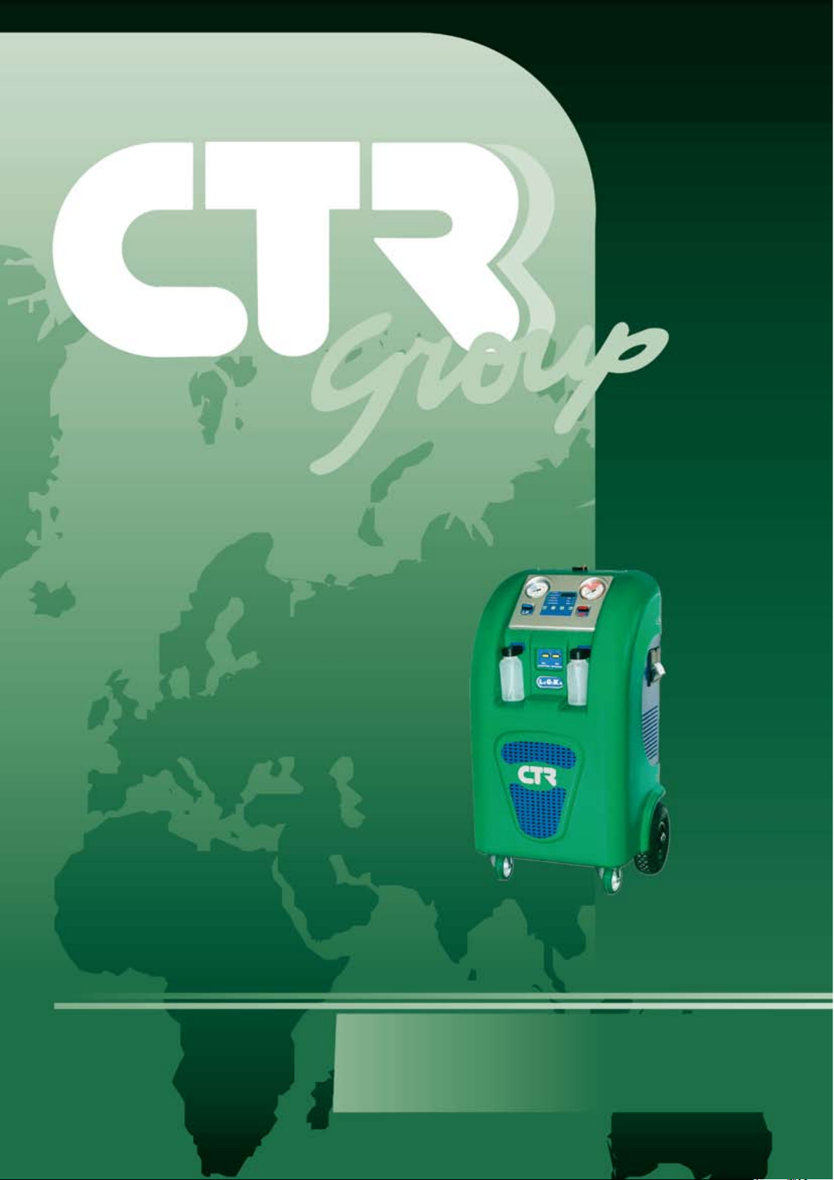
LOGIKA
USE AND MAINTENANCE GUIDE
Page 2
CTR Group thanks you for having chosen this product from its range and recommends that
you read this guide carefully. It contains all the information you will need for correctly using
this model. We therefore recommend that you follow all the safety instructions and read all
sections of this guide before using the machine. We would also advise that you keep the guide
in a safe place for future reference. The contents of this guide are subject to change without
warning, nor is the company under any obligation to incorporate changes and improvements
to the parts already printed. Reproduction or unauthorised translation of any part of this
guide is severely prohibited without written permission from the Company. During the full
warranty period, CTR is responsible for all manufacturing defects, which it undertakes to
eliminate in the shortest possible time.
WARRANTY
The warranty period, under current legislation, is for 12 months from the date of purchase.
The warranty only covers the right to replacement of any faulty part of the machine. The
warranty is not valid in the event that the machine is used for a purpose other than that for
which it was intended, or is tampered with by persons not authorised by our company or, in
any case, using non-compliant methods or parts.
DECLARATION OF COMPLIANCE
Directive 89/392 and 89/336 and subsequent modications and integrations
EN
The Company CTR s.p.a. Via T. ed E. Manzini, 9 - 43100 Parma (Italy) in the name of its
Legal Representative, declares, under its sole responsibility, that the machine System for
managing conditioning and refrigerating plants, Model LOGIKA, complies with the provisions
of directive 89/392 and directive 89/336 and subsequent modications and integrations.
The Company further declares that:
- the year of manufacture is printed on the label (with CE marking) to be found on the machine;
- the technical manufacturing documentation attesting manufacture in compliance with
the Directive is available at our company;
- the machine serial number (if present, in that it is not mandatory) can be found on the
machine.
Parma
....................................................
Signature of authorised representative.
CTR s.p.a.
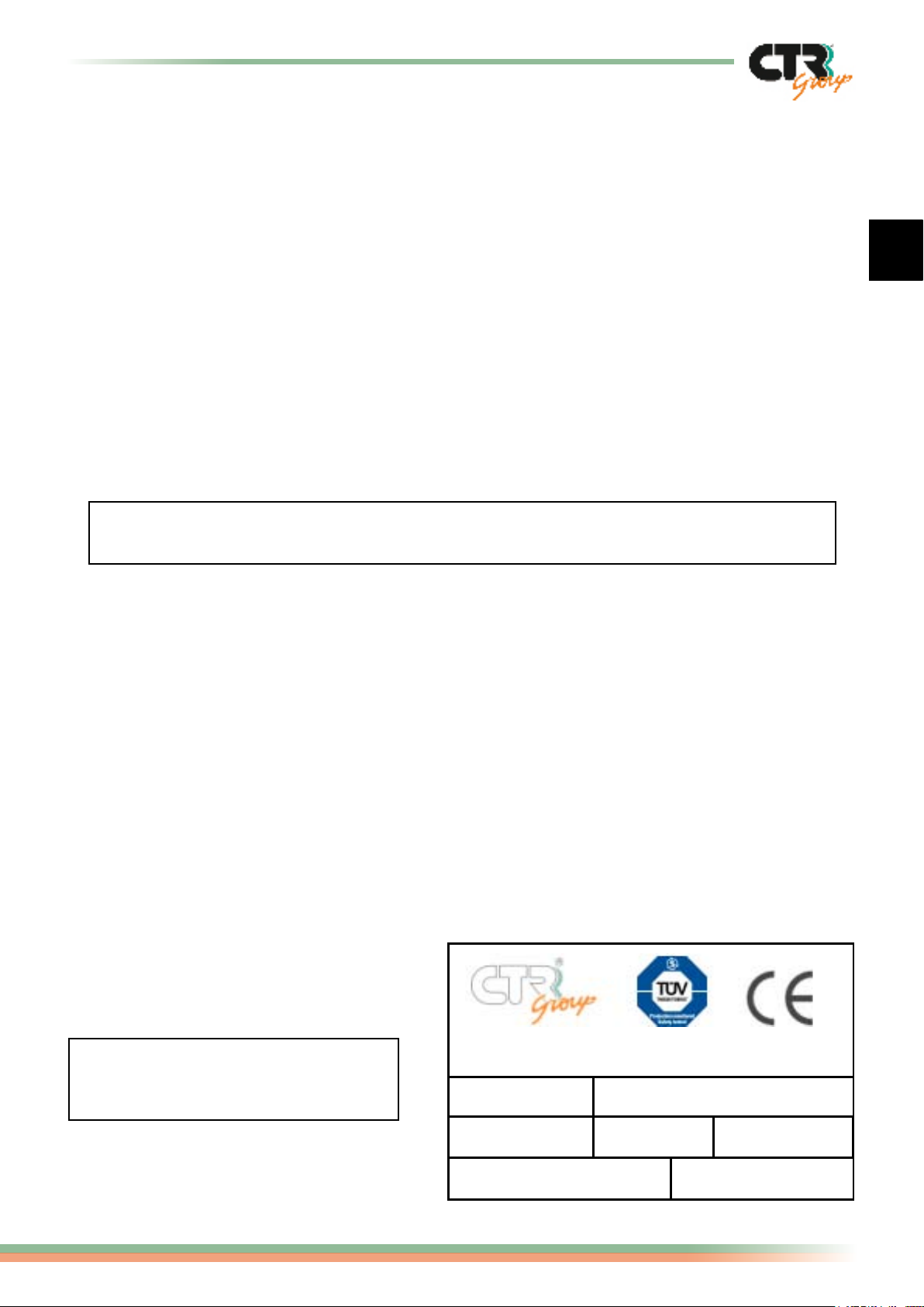
Inspection is certied by the plate
with the CE marking, as illustrated,
positioned on the machine.
Via T. ed E. Manzini n° 9
43100 Parma Made inItaly
modello
LOGIKA
N° matricola
00/ L000
Tensione
230V A/C-50 HZ
Assorbimento A5Potenza assorbita W
1000
Logika - use and maintenance guide
Anno di fabbricazione
0000
refrigerante
R-134a
page
1/16
Page 3
2/16
Logika - use and maintenance guide page
PAR. INDEX PAGE
Declaration of compliance 1
Index - Symbols key 2
1 Introduction 3
2 Technical characteristics 4
3 Warning 5
4 Electricity supply
5 Handling and transport
6 Controls 7
7 Menu structure - Error codes 8
8 Manual operation RECOVERY 9
9 Manual operation VACUUM 10
10 Manual operation CHARGING oil and refrigerant 11
11 AUTOMATIC operation 12
12 Refrigerant topping up 13
13 Recharging of the gas storage cylinder
14 Refrigerant transfer from the unit to an external container
15 General maintenance
15.1 Topping up or changing oil in the vacuum pump
15.2 Changing oil in the compressor and changing lters
15.3 Oil containers
15.4 Charging and service hoses
15.5 Spare parts
16 Labels
6
14
15
SYMBOLS KEY
The key below illustrates the meaning of symbols used in this guide.
DANGER: indicates situations or problems that can be a safety risk and an accident
or life-threatening hazard for people.
CAUTION: indicates situations or problems that are connected with the correct
running of the machine but are not a safety hazard for people.
NO!: do not carry out the operations indicated, as they may compromise the correct
working of the machine.
IMPORTANT: indicates that important instructions of a general nature should be
!
noted but that they do not compromise personal safety or the correct working of the
machine.
CORRECT OPERATION: indicates that this operating method used is correct.
J
NON CORRECT OPERATION: indicates that this operating method used is NOT
L
correct.
Page 4
EN
Logika - use and maintenance guide
3/16
page
1. Introduction
The machine described in this user and maintenance guide is an automatic, multifunctional
digital-setting system for operation with vehicle air conditioning (A/C) plants with functions
for gas recovery, used oil discharge, vacuum, leakage control, oil injection and gas
injection, all managed by a microprocessor and an electronic precision scale.
• Electronic management system: it allows the whole process to be administered through
a microprocessor.
• Electronic precision scale for weighing of gas: it can weigh up to a maximum of 10 Kg.
of refrigerant with a margin of error of 10 grams and is programmed to interrupt the
RECOVERY and CHARGING functions if pre-set for this purpose or should the quantity of
gas exceed the set limits.
• Electronic precision scale for weighing of oil injection: it can weigh up to a
maximum of 500 grams with a margin of error of 10 gr.
• Compressor for refrigerant gas recovery.
• Anti-acid and dehydration lters (n. 3) with hight absorption capacity of water
guaranteeing excellent autonomy.
• Infeed gas still with automatic regulation of refrigerant ow and separated oil coming
from the A/C system with discharge of oil coming from the same.
• Oil separator: positioned immediately after the compressor with automatic oil return at
the end of the cycle.
• Cylinder for refrigerant gas recovery, equipped with an electronically controlled
thermostatic resistor and discharge of incondensable gases.
• Two-stage high-performance vacuum pump.
• Control panel with digital commands.
• Analogic pressure gauges.
• Refrigerant service valve (Ref. Service): allows refrigerant contained in the internal
cylinder of the unit to be sent to a suitable outside container for the purpose.
• Solenoid valve for the discharge of the incondensable gas which are in the bottle.
• Discharge valve for oil coming from the A/C system.
• High-performance exible hoses (n. 2) with rapid coupling and with manual opening
(screw mechanism) for R134a and R12.
• Oil dosing devices (n. 2) 500 cc.
Do not use the machine for any purpose other than which it was designed.
In the case of demolition or hauling away, check the legislation codes that are
applicable in your Country (note that the machine contains refrigerant uids and
we therefore recommend demolition by specialised operators).
The machine is supplied with two distinct models for two types of refrigerant.
Do not use the same model for both types of uids.
Page 5
4/16
Logika - use and maintenance guide page
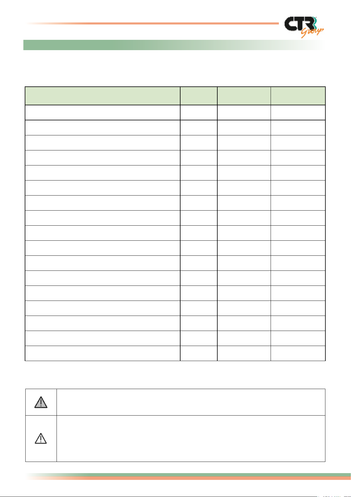
2. Technical characteristics
The technical specications in the chart below are given for the models according to the type
of refrigerant used.
Description
Unit
Measure
R12
Values
R134a
Values
Max. absorbed power W 800 800
Net weight Kg 81 81
Overall dimensions (HxLxP) Mm
1040x540x600 1040x540x600
Fully charged weight kg 100 100
Vacuum ow rate lt/min 66 66
Max. vacuum mbar 0.01 0.01
Filter absorption capacity (rate) gr H2O 80 80
System recovery rate gr/min 400 400
Refrigerant cylinder capacity kg 10 10
Supply voltage V 220/240 220/240
Supply frequency Hz 50 50
Max. absorbed current A 5,0 5,0
Coupling diameter on vehicle (Low Pressure LP) mm 11 13
Coupling diameter on vehicle (High pressure HP) mm 11 16
Max. operating temperature °C 50 50
Min. operating temperature °C 5 5
Max. pressure pneumatic circuit bar 18 18
For supply voltage, always use the value indicated on the machine plate.
The acoustic pressure value for the machine is below 70dBA and therefore no special
precautions need to be taken by the operator even in the case of continuous use
(standard ISO 3746). However, it is the responsibility of the employer to evaluate
noise level exposure of workers in compliance with the directives concerning work
hygiene and safety.
Page 6
EN
Logika - use and maintenance guide
5/16
page
3. Warning
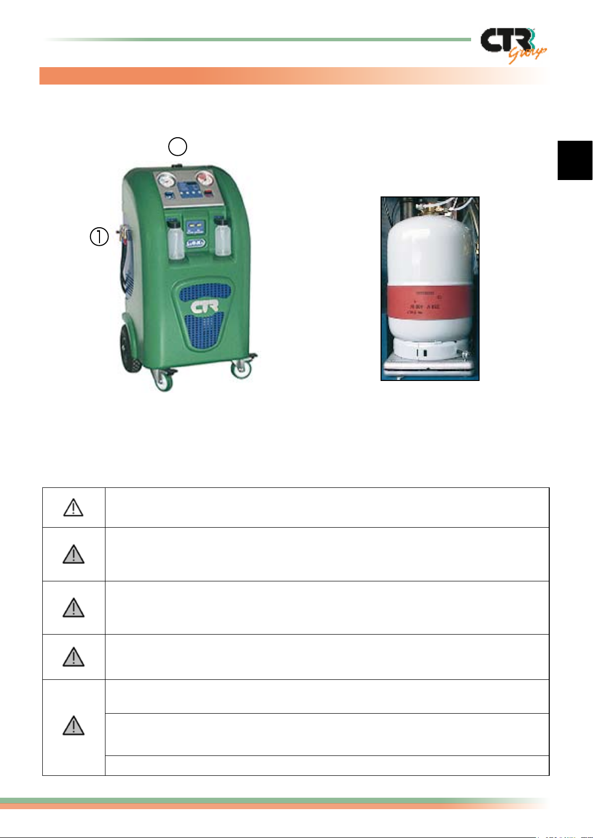
This gure indicates the areas on the machine where there may be a safety hazard during
operations:
2
1) Area where refrigerant may be
ejected.
2) Components carrying live current.
When the machine is operating, check the level of oil in the two tanks making
sure that it does not overow.
We remind you that maintenance and repair carried out by not qualied staff
change the standard of security of the machine and expose the worker to serious
risks.
NEVER disconnect the HP and LP hoses, unless expressly stated in this guide.
Do not manually action the manual lling valves during normal operating phases
unless expressly stated in the instructions.
Always wait some minutes after having switched off the machine to allow the
system to be correctly reset (temperature and pressure).
In no case should the operator use combustible or ammable liquids or detergents
for cleaning the machine.
The machine is delivered with
the cylinder correctly positioned
in its seating on the weighing
scale and already xed with
brackets (n. 2) for this purpose.
During maintenance work do not contaminate the environment with eventual
residual waste products and always follow the prescribed directives in force
regarding disposal.
NEVER disassemble the cylinder.
Page 7
6/16
Logika - use and maintenance guide page
4. Electricity supply
The electrical connections to the machine should be carried out following the instructions
supplied by CTR s.p.a. which, in any case, is not responsible for connections. Check that
the connection point to the main supply is equipped with the prescribed safety devices
in accordance with the relevant codes in force (differential circuit-breaker mechanism and
earthing (grounding system). We advise you to follow the instructions below to correctly
connect up the electrical circuit.
• In the workshop it is necessary to connect the machine up to the mains using the
apposite plug that comes with the machine, checking that the supply voltage
corresponds to the value on the machine plate.
• If you are using an extension cable, check that the cable core section is proportioned
to the length of the cable and that it is positioned where it cannot be damaged in any
way (avoid areas where it can be walked on or damp surfaces).
• In the event of a component breaking, please only contact our after-sales technical
service.
In case of power-down due to a shortage of feeding, wait for approx. 10 seconds
before restarting the machine to allow sufcient time for the electronic components
to be correctly reset.
5. Handling and transport
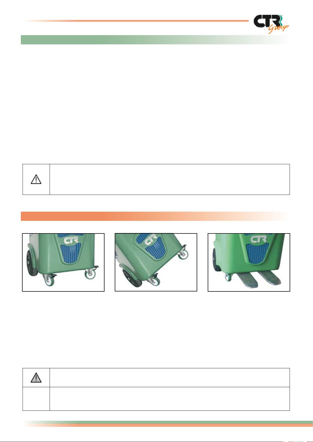
J
Use the wheels on the
bottom of the machine to
push it by hand.
L
Always use the four wheels
to move the machine. Avoid
to tilt it even for short move.
J
To lift the machine at a
distance, use a fork lift
suitable to take the machine
weight (see the section on
technical characteristics)
inserting the forks as
illustrated in the gure
above.
Switch off the machine and disconnect it from the electric system.
Please keep original packaging (pallet, box and polystyrene) for possible future
!
shipments.
Page 8
EN
Logika - use and maintenance guide
7/16
page
6. Controls
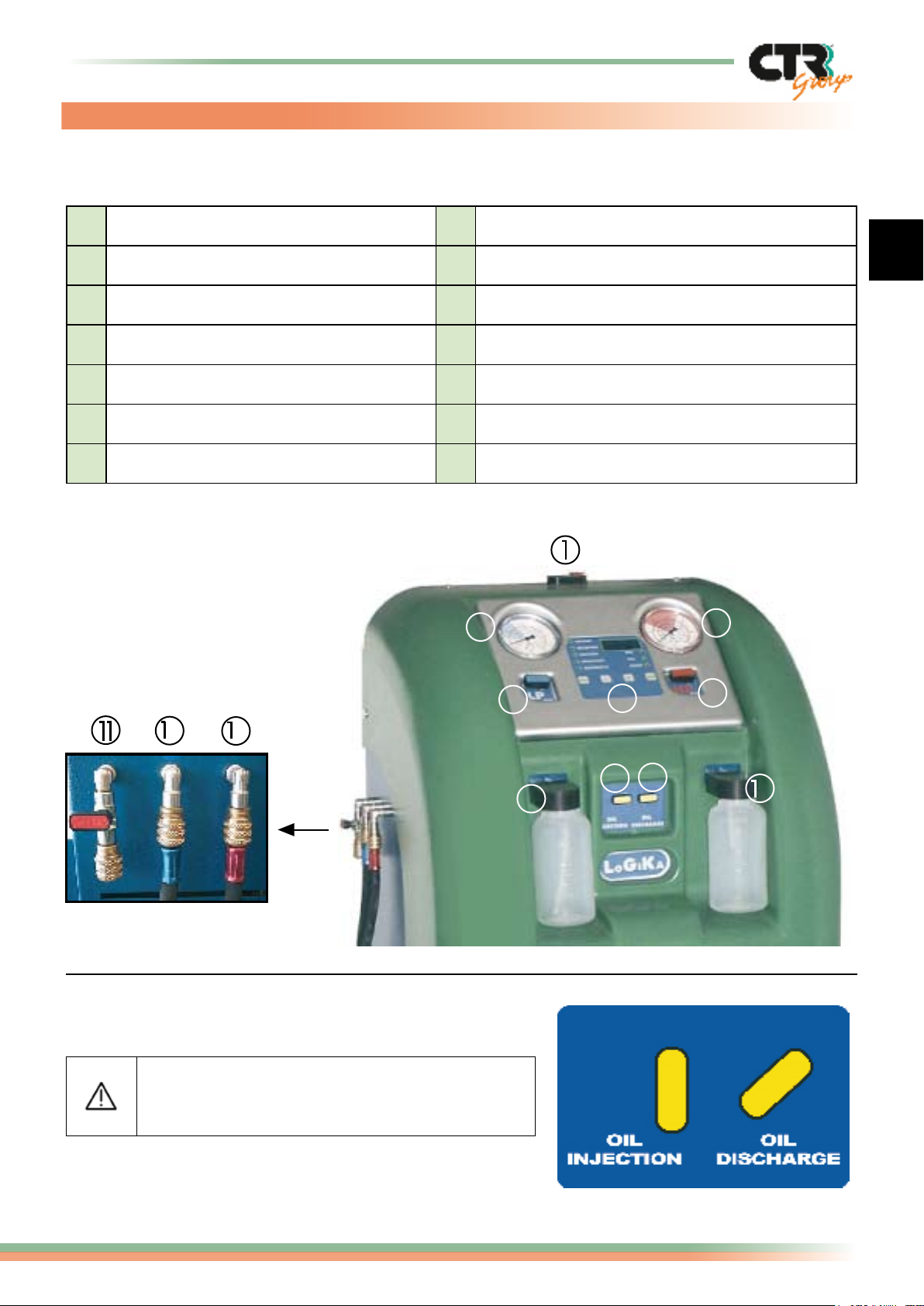
This section describes the main functions present on the machine control panel:
1 ON/OFF Emergency switch 8 Oil injection valve (OIL INJECTION)
2 Control panel 9 Oil discharge valve (OIL DISCHARGE)
3 Low pressure gauge 10 bar 10 Used oil discharge tank connection
4 High pressure gauge 30 bar 11 Ref. Service coupling
5 LP valve (low pressure) 12 Low pressure connection (Blue)
6 HP valve (high pressure) 13 High pressure connection (Red)
7 Oil injection tank connection
3
5
2
4
6
2
3
7
During the normal working of the machine
keep the valve no. 8 completely open and
the valve no. 9 open to approx. 45°.
8
9
0
Page 9
8/16
Logika - use and maintenance guide page
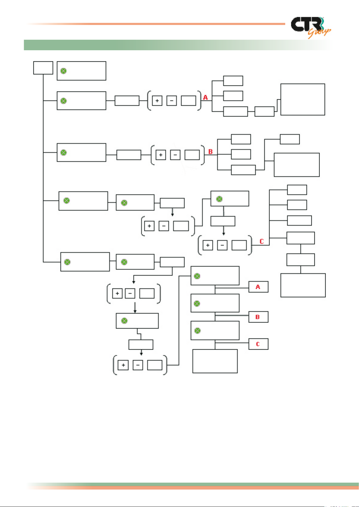
7. Menu structure
SEL
WEIGHT
RECOVERY
VACUUM
CHARGING
AUTO
1800
OIL
0030
OK
OK
OK
E1
E2
T200 T60
E3
E4
T300
GAS
00.70
OK
Whole gas
recovered.
End
operation
E5
0000
End
operation
E6
E7
E9
OIL IN
AUTOMATIC
OIL
OK
GAS
00.70
OK
0030
RECOVERY
AUTO
VACUUM
1800
CHARGING
0000
End
operation
GAS IN
Possible error codes:
E0 = Cylinder full. It is not possible to recover gas.
E1 = Excessive quantity of gas programmed for recovery.
E2 = Recovery time expired.
E3 = Pressure present in the system at the start or during the vacuum cycle.
E4 = Time to achieve vacuum expired.
E5 = Leaks found in vacuum control cycle.
E6 = Insufcient quantity of refrigerant for programmed charge.
E7 = Refrigerant/oil charge time expired.
E9 = Insufcient quantity of oil injection.
0000
End
operation
Page 10
EN
Logika - use and maintenance guide
9/16
page
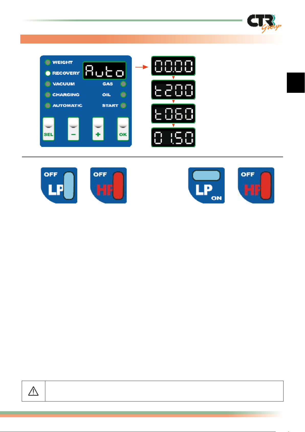
8. Manual operation “RECOVERY”
1- Quantity of gas
during the recovery
2- Wait
3- Oil discharge
4- End of operation
(Ex. 1,5 Kg. gas recovered)
1) LP and HP valves open 2) LP valve closed and HP valve open
- Connect up the high and low pressure hoses with the A/C plant.
- Open the two high and low pressure valves HP-LP (ex. 1) or, in case of only one service
point, open the corresponding valve (ex. 2).
- Use the SEL key to select RECOVERY, indicated by the side led light.
- The display visualizes the word AUTO. By pressing the key OK, the unit will recover the entire
refrigerant in the circuit. It is possible to pre-set the quantity of refrigerant to be recovered by
using the “+” and “-” keys. In that case, the times T200 and T60 will be deactivated.
- During this operation, it is possible to monitor the partial weight of gas recovered on the display.
- Terminated the pressure in the A/C system, the display visualizes T200 (seconds) for eventual
refrigerant still blocked in the system in the form of micro-frozen granules of oil and humidity.
- At the end, the machine discharges the oil recovered for 60 seconds. Once the oil discharge phase
has terminated, the recovery phase begins if pressure is present. At the end of this phase the total
quantity of refrigerant recovered is visualized and is followed by an acoustic signal indicating the end
of the operation. The data of the complete operation will be automatically printed.
Possible error codes:
E0 = Cylinder full. It is not possible to recover gas.
E1 = Excessive quantity of gas programmed for recovery.
E2 = Recovery time expired.
The RECOVERY operation must be carried out with the engine switched off.
Page 11
10/16
Logika - use and maintenance guide page
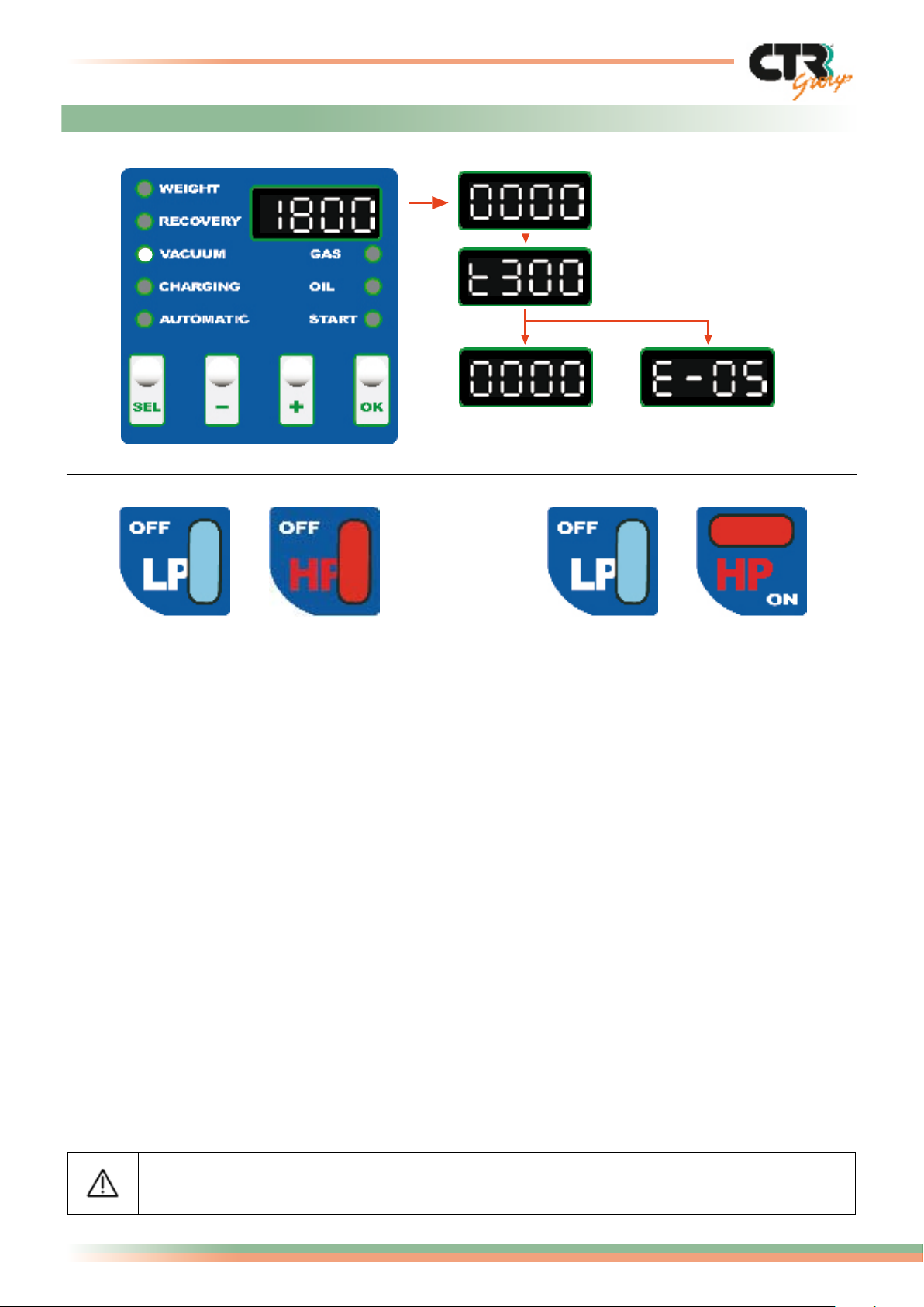
9. Manual operation “VACUUM”
1- Time for vacuum expired
2- Leakage control
3- End of
vacuum phase
1) LP and HP valves open 2) LP valve open and HP valve closed
3a- Leak
presence
- Connect up the high and low-pressure hoses with the A/C plant.
- Open the two high and low pressure valves HP-LP (ex. 1) or, in case of only one service
point, open the corresponding valve (ex. 2).
- Use the SEL key to select VACUUM, indicated by the lateral led light.
- The display visualizes the pre-set time of 1800 seconds (30 minutes) that can be
changed by using the “+” and “-” keys.
- Press the OK key to proceed with the vacuum function. If the pre-set time doesn’t
decrease, after 10 minutes the function will stop and the error code E4 will appear
(time to achieve vacuum expired).
- Check leaks: using the countdown function for a maximum of 300 seconds (5 minutes).
In case of leaks the operation will stop and the display will visualize the error code E5
indicating a leak in the plant.
- If this phase ends without problems, then the display will visualize “four zeros” (0000)
indicating that the vacuum phase has been completed.
Possible error codes:
E3 = Pressure present in the system at the start or during the vacuum cycle.
E4 = Time to achieve vacuum expired.
E5 = Leaks found in vacuum control cycle.
The VACUUM operation must be carried out with the engine switched off.
Page 12
EN
Logika - use and maintenance guide
11/16
page
10. Manual operation “CHARGING”
This function of the system allows refrigerant liquid and oil to be injected into the system
according to a pre-programmed quantity.
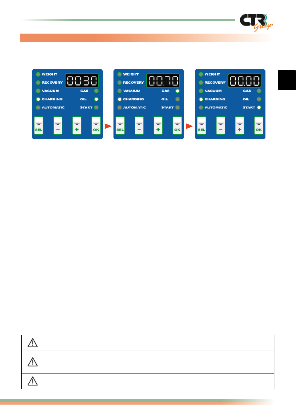
1- Setting oil charging
- Connect up the high and low pressure hoses.
- We advice you to open only the HP valve.
- If the HP service point is not present, the charge must be carried out in LP. At the end
wait for three minutes before starting the A/C system.
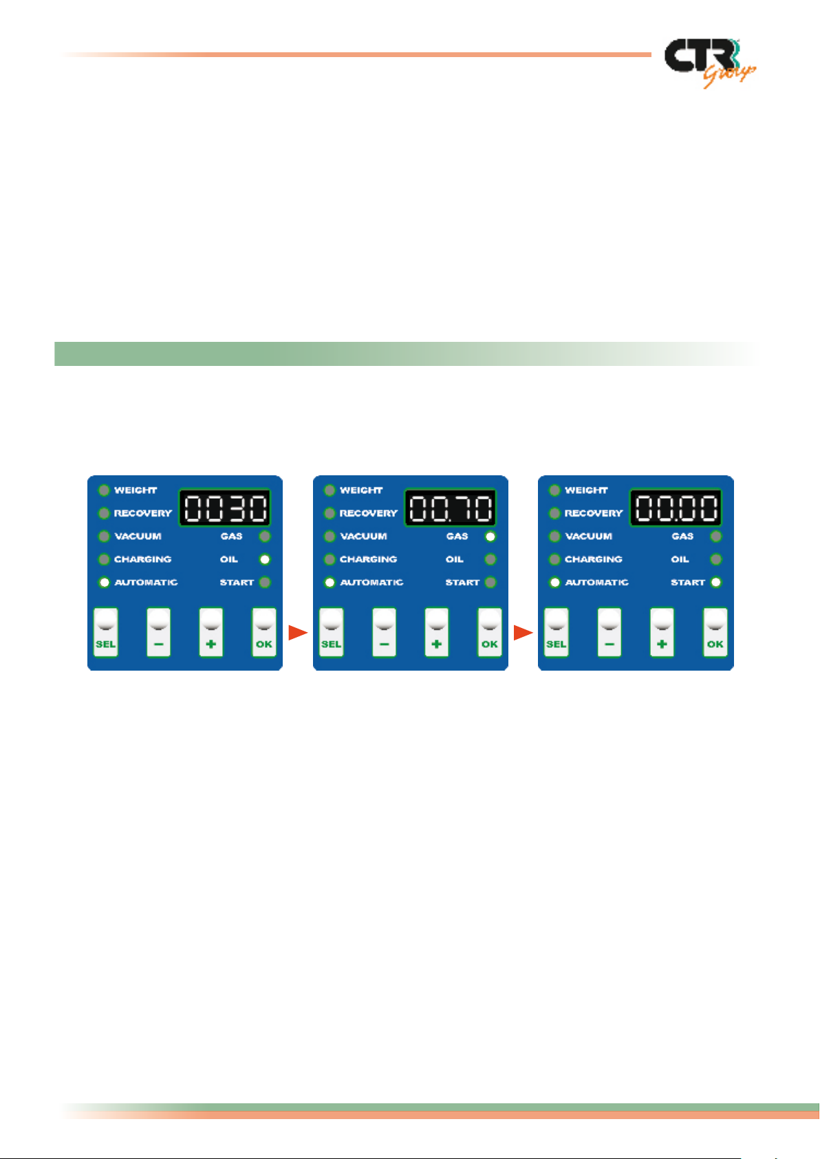
- Use the SEL key to select CHARGING, indicated by the lateral led light (g. 1).
- Once the CHARGING operation has been selected, the led OIL position on the display
lights on and the programmed quantity 30 gr. (indicated as 0030) of fresh oil appears
on the display (g. 1). This quantity can be changed by using the “+” and “-” keys.
- Press the OK key to conrm.
- The led light OIL disappears and the led GAS position lights on. The programmed
quantity of 700 gr. (indicated as 00.70 kg.) appears on the display (g. 2) and it can
be changed by using the “+” and “-” keys.
- Press the OK key to conrm.
- The led light GAS disappears and the led START lights on to start the charging operation (g. 3).
- During the oil and gas charging the display visualizes the grams with a margin of error of 10 gr.
- Oil will be charged only after the vacuum operation has been carried out in the A/C system.
- If the quantity of oil and refrigerant are lower than the min. quantity, the error codes E6-E9
will be visualized to indicate that you must restore the levels before starting the operation.
Then re-select the CHARGING phase.
- Acoustic sound of end operation and data printing.
- Wait for three minutes before starting the A/C system.
2- Setting gas charging 3- Start operation
Possible error codes:
E6 = Insufcient quantity of refrigerant for programmed charge.
E7 = Refrigerant/oil charge time expired.
E9 = Insufcient quantity of oil injection.
Min. level of refrigerant in the cylinder = 1 Kg.
Min. level of fresh oil in the container = 100 gr.
Sometimes, at the end of charging, you could hear a pressure leak and a countdown will
appear on the display. This is the automatic function of air discharge or incondensable
gases from the cylinder.
The CHARGING operation must be carried out with the engine switched off.
Page 13
12/16
Logika - use and maintenance guide page
How to empty the hoses of the unit:
- After having carried out the charging procedure, maintain the high and low pressure
hose connections but close the two HP-LP valves, start the vehicle engine and wait a few
minutes until the A/C plant is fully running.
- In case of only one service point, close the HP or LP valve used and disconnect the hose
from the vehicle.
- In case of two service points, disconnect the high pressure (HP) hose from the vehicle
and open the two valves HP-LP on the control panel to allow the gas contained in the
hoses to be discharged through the low pressure terminal to the vehicle. Wait until HP
and LP fall to about 2 bar, then disconnect the remaining low-pressure hose (LP).
Switch off the engine.
11. “AUTOMATIC” operation
This procedure allows the system to carry out gas recovery, recovered oil discharge, vacuum,
leakage control, oil charge and gas charge in a completely automatic mode and with invariable
times for each operation respect to the manual mode.
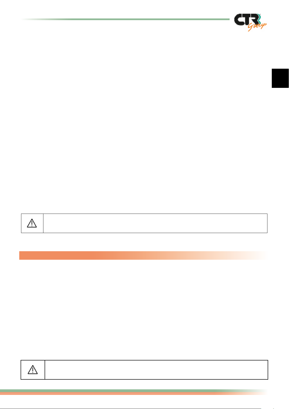
1- Setting oil charging
2- Setting gas charging
3- Start operation
- Connect up the high and low pressure hoses.
- Open the HP and LP valves; we advice you to close the LP valve at the end of the
vacuum phase. If at the end of this phase it is not possible to close the LP valve, once
the charging operation has come to an end, wait for three minutes before starting the
A/C system, or, in case of only one service point, open the corresponding valve.
- Use the SEL key to select AUTOMATIC, indicated by the lateral led light (g. 1).
- Once the AUTOMATIC operation has been selected, the led OIL position on the display
lights on and the programmed quantity 30 gr. (indicated as 0030) of fresh oil appears on
the display (g. 1). This quantity can be changed by using the “+” and “-” keys.
- Press the OK key to conrm.
- The led light OIL disappears and the led GAS position lights on. The programmed
quantity 700 gr. (indicated as 00.70 kg) appears on the display and it can be changed
by using the “+” and “-” keys (g. 2).
- Press the OK key to conrm.
- The led GAS disappears and the led START lights on to start the Automatic operation (g. 3).
- If the quantity of oil and refrigerant are lower than the minimum quantity, the error
codes E6-E9 will be visualized to indicate that you must restore the levels before
starting the operation, then re-select the AUTOMATIC phase.
- During the operation, the display will visualize times, quantities and errors of the different phases.
Page 14
EN
Logika - use and maintenance guide
13/16
page
- Acoustic sound of end operation and data printing.
- Wait for three minutes before starting the A/C system.
How to empty the hoses of the unit:
- After having carried out the charging procedure, maintain the high and low pressure
hose connections but close the two HP-LP valves, start the vehicle engine and wait a few
minutes until the A/C plant is fully running.
- In case of only one service point, close the HP or LP valve used and disconnect the hose
from the vehicle.
- In case of two service points, disconnect the high pressure (HP) hose from the vehicle
and open the two valves HP-LP on the control panel to allow the gas contained in the
hoses to be discharged through the low pressure terminal to the vehicle. Wait until HP
and LP fall to about 2 bar, then disconnect the remaining low-pressure hose (LP).
Switch off the engine.
Possible error codes:
E0 = Cylinder full. It is not possible to recover gas.
E1 = Excessive quantity of gas programmed for recovery.
E2 = Recovery time expired.
E3 = Pressure present in the system at the start or during the vacuum cycle.
E4 = Time to achieve vacuum expired.
E5 = Leaks found in vacuum control cycle.
E6 = Insufcient quantity of refrigerant for programmed charge.
E7 = Refrigerant/oil charge time expired.
E9 = Insufcient quantity of oil injection.
The AUTOMATIC operation must be carried out with the engine switched off.
12. Refrigerant topping up
If refrigerant is already present in the A/C plant, the only way to inject gas is by TOPPING UP.
To carry out this phase, it is necessary, after having connected up the unit to the A/C plant,
to start the vehicle engine and wait a few minutes until the A/C plant is fully running.
- Connect the low-pressure hose (blue).
- Partly open the low pressure valve LP.
- Press the SEL key and select the CHARGING function on the control panel.
- Set the oil quantity at ZERO grams and press OK.
- Programme the desired quantity of gas by using the “+” or “-”.
- Press the OK key to start topping up.
This is the only phase to be carried out with the engine running.
Page 15
14/16
Logika - use and maintenance guide page
13. Recharging of the gas storage cylinder
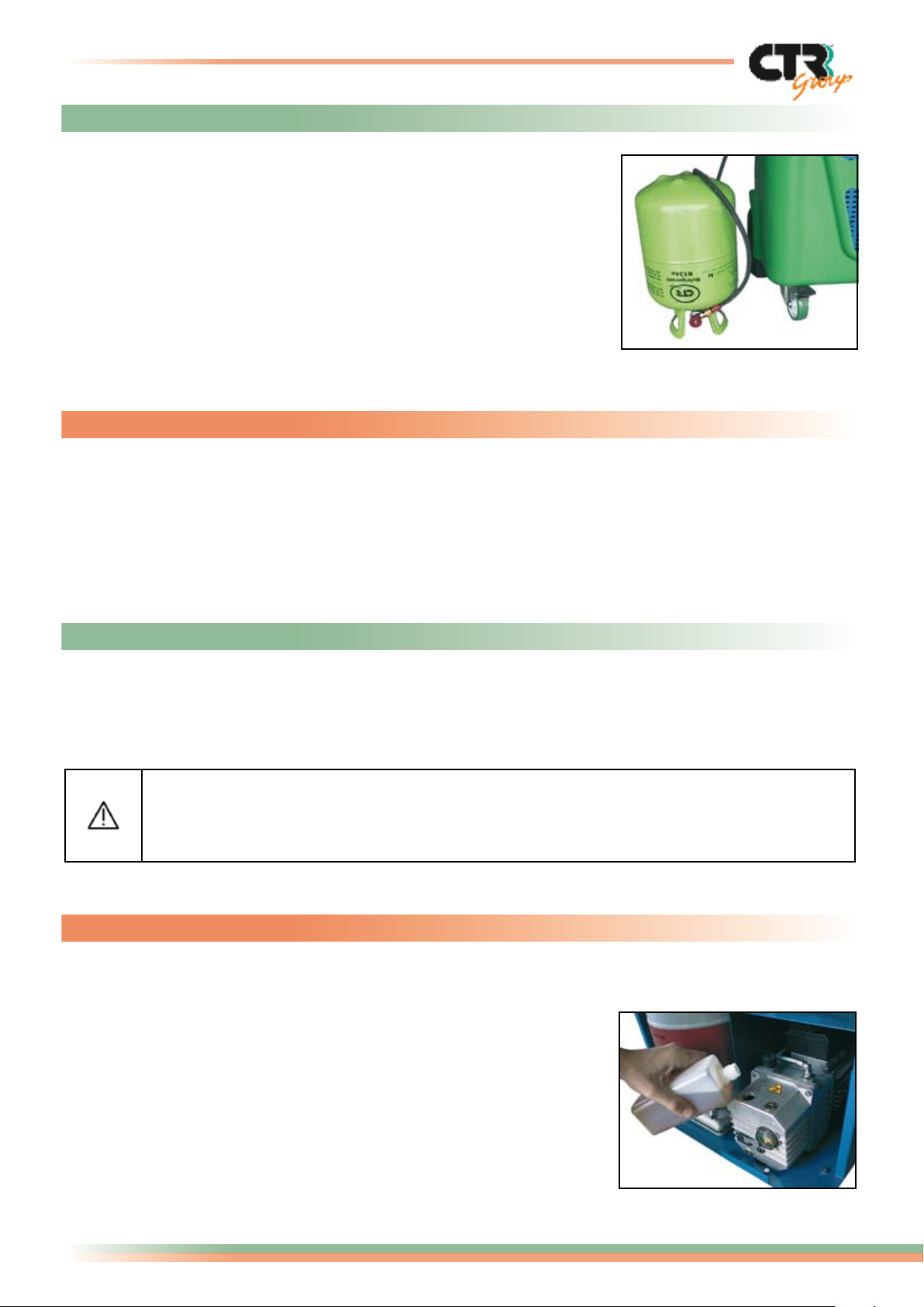
Take the red high-pressure hose HP; remove the rapid coupling at its end,
connect the hose to an external cylinder containing refrigerant and carry out
the recovery procedure (see the section Manual operation “RECOVERY”).
If the external cylinder is not equipped with an internal pick-up
tube, it should be turned upside down so that the gas flows out in
a liquid state. We would recommend that the pressure value be
maintained at approximately 3 bar at this stage of recovery visible
on the HP pressure gauge by partially opening the valve on the
external cylinder. When the desired quantity has been reached, close the
valve of the external bottle and wait for the end of recovery operation. Then
disconnect the hose and re-screw the rapid coupling.
14. Refrigerant transfer from the unit to an external container
To carry out emptying of the cylinder the operator should:
- Switch on the machine, connect a service hose with the Ref. Service valve and the other
end of the hose with a bottle or another external container; open the valves.
- Once the transfer has come to an end, close the valves and carry out the recovery
operation of the gas left in the hose.
15. General maintenance
Periodically:
- Check the oil level in the vacuum pump every three months.
- Change the oil in the vacuum pump every six months even when the unit is not used regularly.
- Check the calibration of the scale.
The station is equipped with a recovery cycle counter; when the lters
are saturated, every time the unit is switched on, a display with the
word “FILT” will indicate that they need to be changed shortly.
Contact our after-sales service centre.
15.1 Topping up or changing oil in the vacuum pump
To top up or change oil in the vacuum pump, the operator should use oils that are designed
for use in vacuum pumps.
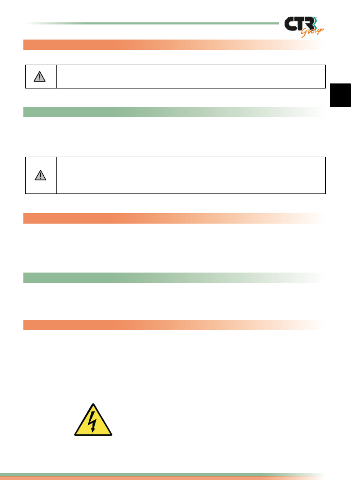
To top up, the operator should unscrew the cap of the vent (see
illustration) and top up with sufcient oil to the level of the screw of
the indicator light. Finally, replace the cap on the vent.
To do a complete oil change it is necessary to:
- run the pump for 10 minutes;
- disconnect the machine from the power supply;
- disassemble the drainage cap positioned on the underside of the
pump; wait until all the oil has drained out, and replace the cap;
- unscrew the vent cap and ll up with new oil until the level is
halfway up the spyglass;
- replace the vent cap.
Page 16
EN
Logika - use and maintenance guide
15/16
page
15.2 Changing oil in the compressor and changing lters
Qualied personnel should only carry out this operation.
We recommend that you contact our after-sales technical service centre.
15.3 Oil containers
The machine is supplied with one oil container for new oil injection. If it is necessary to use
more than one type of oil, then separate containers should be requested for each different
oil type.
Never mix different types of lubricant. Always check the type of oil that should
be used by a specic A/C plant (according to the type of compressor installed).
CTR s.p.a. will be happy to provide technical sheets, on request.
15.4 Charging and service hoses
The machine is supplied with connecting hoses to the A/C plant of length equal to 1800 mm.
Should the standard tubing not be of sufcient length for your requirements, tubing length
equal to 3000 mm. is available at our authorised distributors.
15.5 Spare parts
All spare parts for LOGIKA are available at our authorised dealers and are distributed by CTR s.p.a.
16 Labels and markings
This is a list of the meanings of the labels present on the machine:
Indicates the type of refrigerant
R134a
compatible for the type of machine.
Lightening symbol on bright yellow
background (indicates parts carrying
high voltage with an electric-shock hazard).
Page 17
© by CTR Group S.p.A.
all rights reserved
CTR Group s.p.a. - Via T. ed E. Manzini, 9 - 43100 Parma - Italy
Tel. +39 0521 957611 - Fax. +39 0521 957677
internet: http://www.ctrgroup.it • e-mail: [email protected]
 Loading...