

Page 1
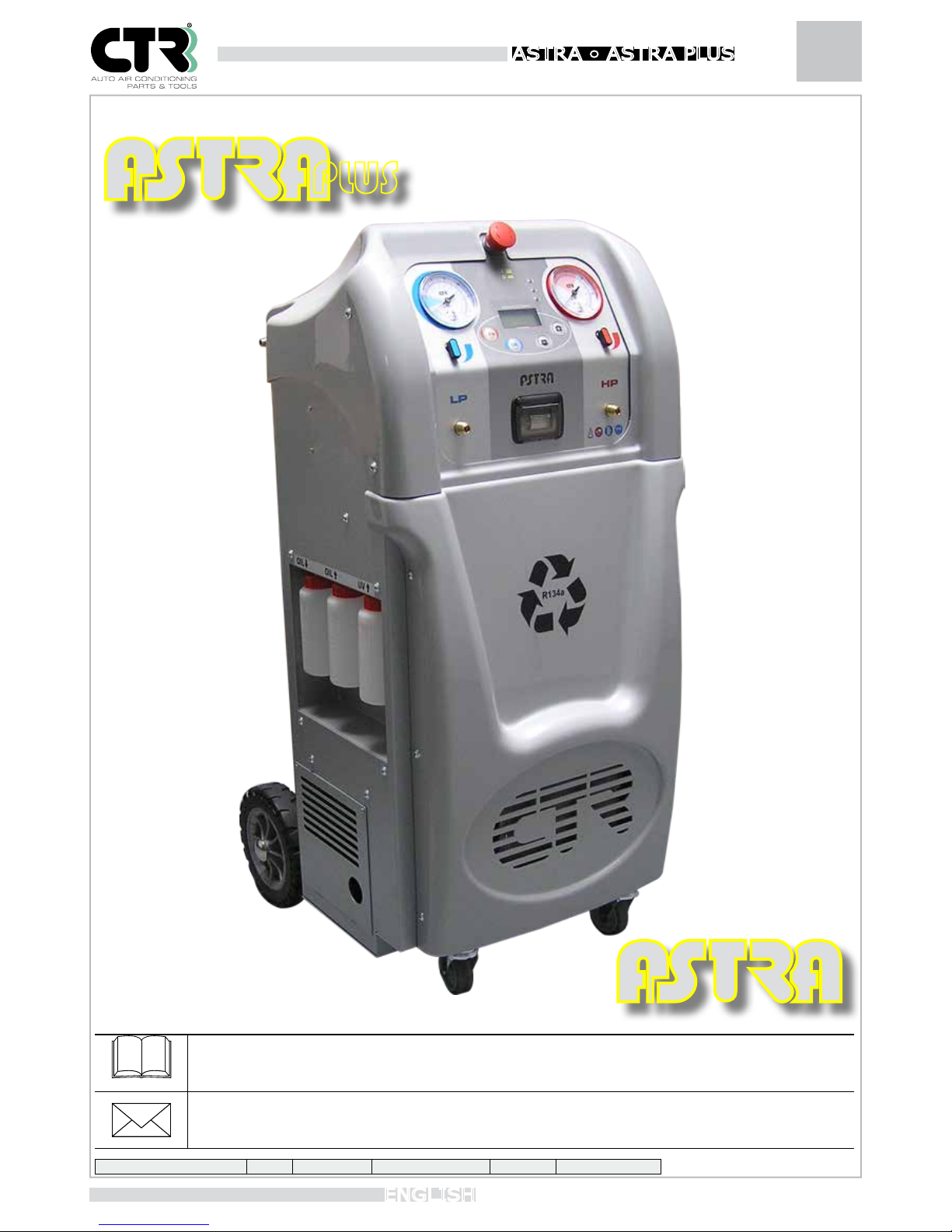
Instruction Booklet
ENGLISH
ASTRA • ASTR A PLUS
PLUS
Carefully read this use and maintenance manual before using the unit.
CTR S.R.L. Via T. ed E. Manzini n° 9, 43126 Parma (Italy)
Tel. +39 0521/957611 - Fax. +39 0521/957677
Internet:www.ctr-srl.com E-mail: [email protected]
Revision number 1 Code Date 02/03/2016
Page 2
Instruction Booklet ASTRA • ASTR A PLUS
2
ENGLISH
Page 3
Instruction Booklet
3
ENGLISH
ASTRA • ASTR A PLUS
CTR S.R.L. would like to thank you for buying a product from its range and invites you to read this manual. Inside this manual you
will find all the information you need for correctly using the unit; please follow the instructions contained in this manual carefully and
read through every section. You should also store the manual carefully to keep it in good readable condition. The content of this
manual may be modified without prior notice, nor further obligations, in order to include changes and improvements to the
instructions already provided. No part of this manual may be reproduced or translated without prior written consent of the owner.
CTR S.R.L. shall be responsible for any manufacturing defect that may arise during the entire warranty period and undertakes to
correct any defect as promptly as possible.
WARRANTY
The warranty is valid for 12 months from the date of purchase. The warranty covers only the replacement of faulty parts. The
warranty shall be invalidated if the equipment is found to have been improperly used or tampered with by people not authorized
by us or if nonconforming components or techniques have been used.
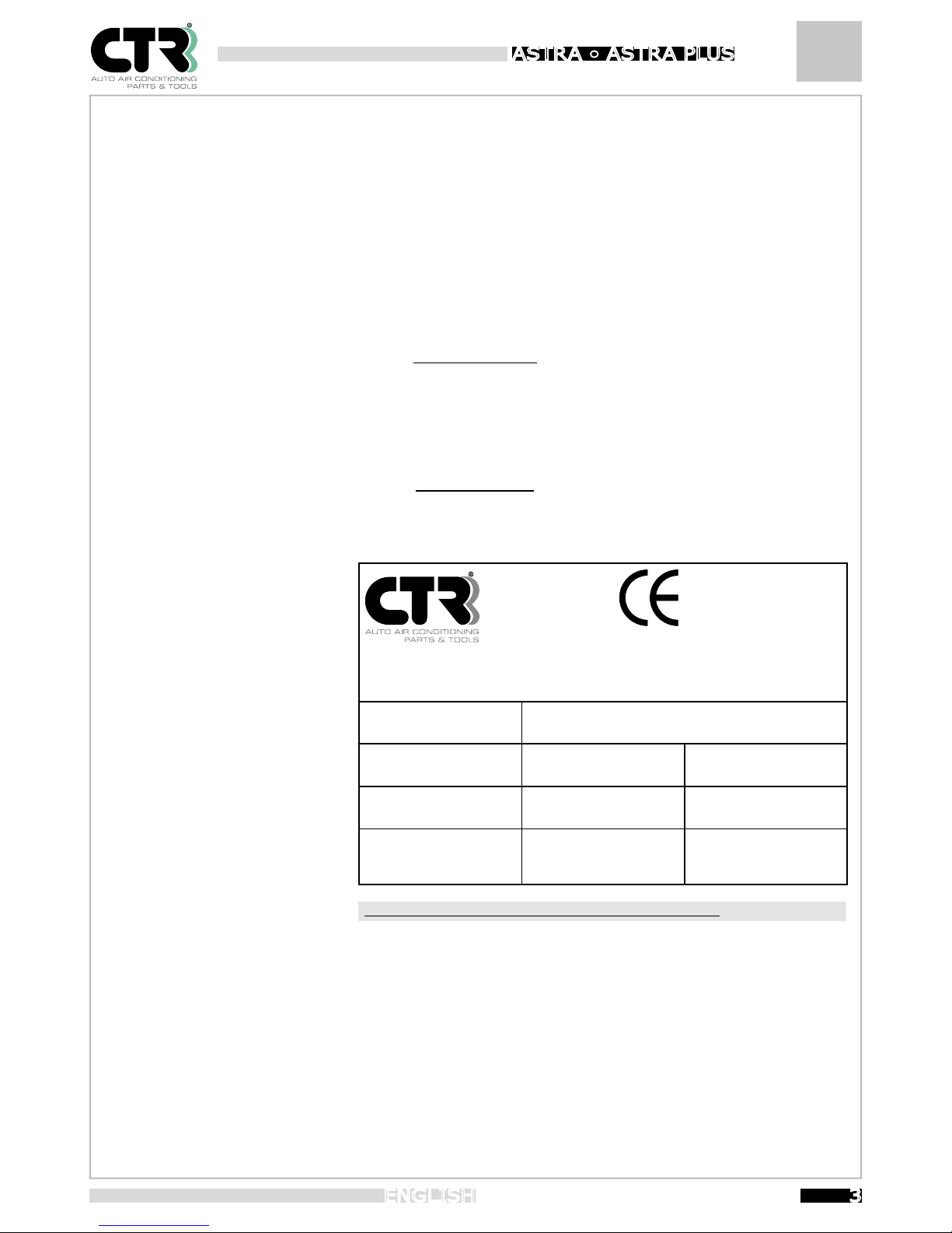
LABELLING
Model Astra
CTR S.R.L.
via T. ed E. Manzini,9
43126 - PARMA ITALY MADE IN ITALY
Model
ASTRA
Voltage
Serial N°: Adsorption A Absorbed power W
Max pressure. Min Temperature. Max temperature.
Refrigerant
R134a
Year of manufacture
Risk category under
97/23/CE I
This label is merely indicative. The complete data label is afxed onto the unit.
Page 4
DICHIARAZIONE DI CONFORMITA’
FARE RIFERIMENTO AL DOCUMENTO A CORREDO DEL MANUALE D’USO
DECLARATION OF CONFORMITY
REFER TO THE ATTACHED DOCUMENT OF THE USER MANUAL
DÉCLARATION DE CONFORMITÉ
CONSULTEZ LE DOCUMENT ATTACHÉ AU MANUEL D’UTILISATION
DECLARACION DE CONFORMIDAD
CONSULTE EL DOCUMENTO ADJUNTO AL MANUAL DEL USUARIO
KONFORMITÄTSERKLÄRUNG
VERWEIS AUF DAS DOKUMENT, DAS DEM HANDBUCH ANGEBOTEN IST
Page 5
Instruction Booklet
5
ENGLISH
ASTRA • ASTR A PLUS
CTR S.R.L. would like to thank you for buying a product from its range and invites you to read this manual. Inside this manual you
will find all the information you need for correctly using the unit; please follow the instructions contained in this manual carefully and
read through every section. You should also store the manual carefully to keep it in good readable condition. The content of this
manual may be modified without prior notice, nor further obligations, in order to include changes and improvements to the
instructions already provided. No part of this manual may be reproduced or translated without prior written consent of the owner.
CTR S.R.L. shall be responsible for any manufacturing defect that may arise during the entire warranty period and undertakes to
correct any defect as promptly as possible.
WARRANTY
The warranty is valid for 12 months from the date of purchase. The warranty covers only the replacement of faulty parts. The
warranty shall be invalidated if the equipment is found to have been improperly used or tampered with by people not authorized
by us or if nonconforming components or techniques have been used.
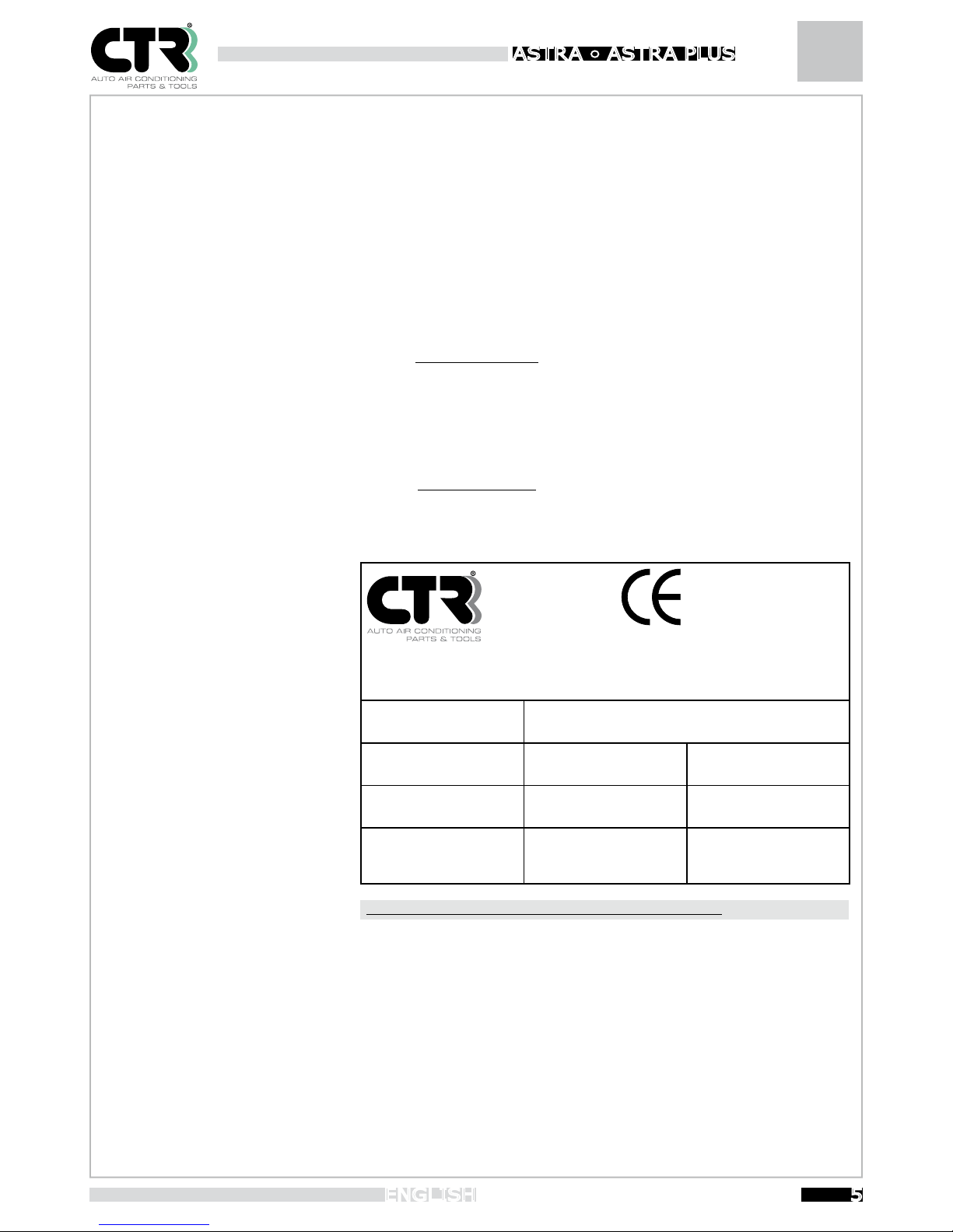
LABELLING
Model Astra Plus
CTR S.R.L.
via T. ed E. Manzini,9
43126 - PARMA ITALY MADE IN ITALY
Model
ASTRA PLUS
Voltage
Serial N°: Adsorption A Absorbed power W
Max pressure. Min Temperature. Max temperature.
Refrigerant
R134a
Year of manufacture
Risk category under
97/23/CE II
This label is merely indicative. The complete data label is afxed onto the unit.
Page 6
DICHIARAZIONE DI CONFORMITA’
FARE RIFERIMENTO AL DOCUMENTO A CORREDO DEL MANUALE D’USO
DECLARATION OF CONFORMITY
REFER TO THE ATTACHED DOCUMENT OF THE USER MANUAL
DÉCLARATION DE CONFORMITÉ
CONSULTEZ LE DOCUMENT ATTACHÉ AU MANUEL D’UTILISATION
DECLARACION DE CONFORMIDAD
CONSULTE EL DOCUMENTO ADJUNTO AL MANUAL DEL USUARIO
KONFORMITÄTSERKLÄRUNG
VERWEIS AUF DAS DOKUMENT, DAS DEM HANDBUCH ANGEBOTEN IST
Page 7
Instruction Booklet
7
ENGLISH
ASTRA • ASTR A PLUS
CAP CONTENTS PAG
Declaration of conformity 3
Symbols 8
1. Introduction 8
2. Technical features 9
3. Safety warnings 10
3.1 Working environment 10
3.2 Preliminary checks 11
3.3 Use 11
3.4 Maintenance 12
3.5 Electrical power supply 12
4. Handling and transport 13
5. General operating rules 14
5.1 Main panel 14
5.2 Operating phases 15
5.3 Use 15
5.4 “Automatic” operation 16-17
5.5 “Recovery” operation 18
5.6 “Vacuum” operation 19
5.7 “CHARGE TO VEHICLE” operation 19-20
5.8 Pipe drainage procedura 21
5.9 Refrigerant topping-up 21
5.10 “Recharge cylinder” operation 22
6. “Service” Menu 22
6.1 Service menu for the operator 22-23
6.2 Service menu for technical staff 23-24
7. Refrigerant transfer from the unit to an external container 24
8. Routine maintenance 24
8.1 Refrigerant lter replacement 24-25
8.2 Vacuum pump replacement 25
9. Oil/UV tracer containers 26
9.1 Service pipes 26
9.2 spare parts 26
9.3 Adhesive labels 26
10. SD Card database update 27
11. Printer 27-28
12. Troubleshooting 29
13. Error messages 30
Page 8
Instruction Booklet ASTRA • ASTR A PLUS
8
ENGLISH
SYMBOLS
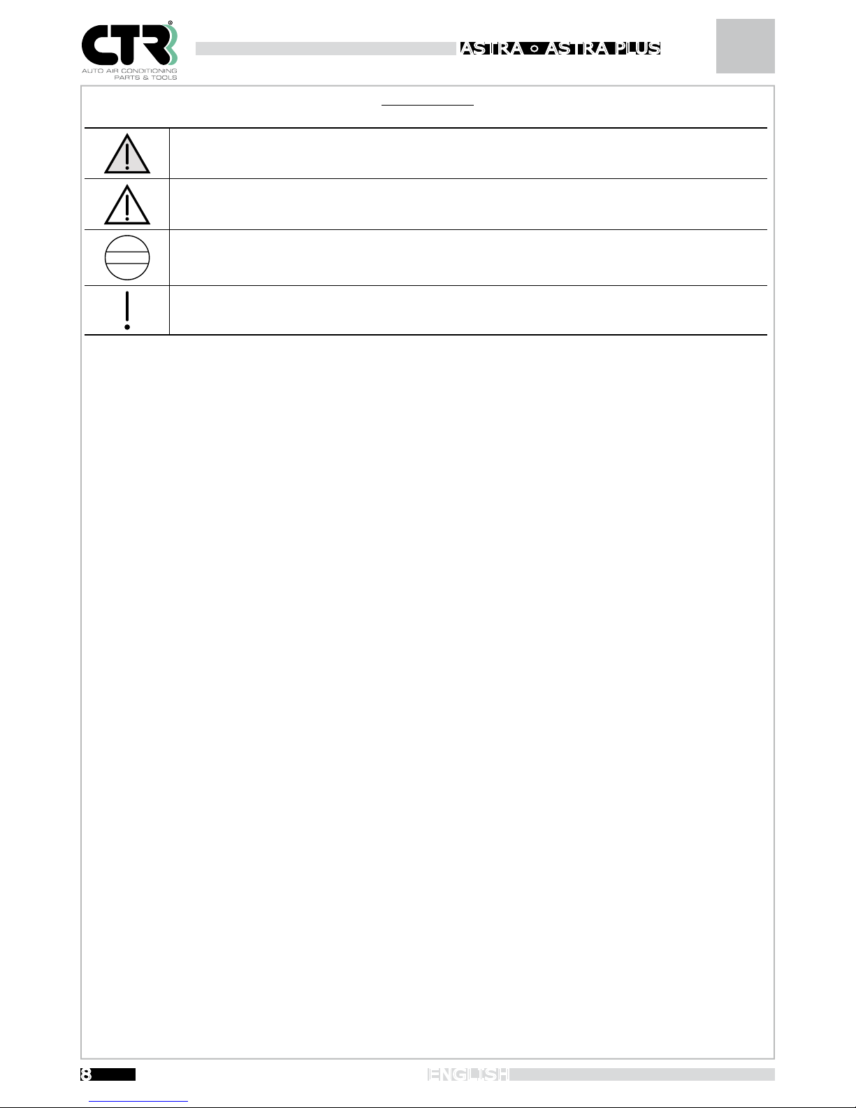
Below is a brief legend explaining the symbols used.
DANGER: draws your attention to situations or problems that may cause injury or a risk of death.
WARNING: draws your attention to situations or problems connected with the efficiency of the unit, which do
not pose a risk to the safety of persons.
PROHIBITION: do not perform the operations indicated as they may compromise the efficiency of the unit.
IMPORTANT: draws your attention to important information of a general nature, which does not compromise
personal safety or proper functioning of the unit.
1. Introduction
The unit described in this use and maintenance manual is a fully automatic multifunctional system with digital setting, with a
database for first-installation automotive air conditioning systems and performs the following operations: gas recovery, used oil
discharge, vacuum phase, leak test, new oil refilling, UV tracer recharge, gas recharge. All these operations are controlled by a
microprocessor and electronic precision scales.
Listed below are the main components and their functions :
• Electronic control: controls the entire process by means of a microprocessor.
•
Electronic gas weighing scale: can weigh a maximum of 30 kg of refrigerant with a resolution of 5 g and interrupt the RECOVERY
and CHARGE functions if programming or reaching uncontrollable quantities during the operation.
• 12 cc refrigerant gas recovery compressor.
• Two anti-acid recovery filters and a new-concept dehydrator with reduced environmental impact, low cost and fast to replace.
• Input gas distiller with automatic flow regulator for the separated refrigerant and oil coming from the A/C system
with oil dis charge.
• Oil separator positioned directly behind the compressor with automatic return during the recovery cycle.
•
12-litre cylinder (model Astra) and 19-litre cylinder (model AstraPlus) for refrigerant gas recovery, equipped with an electronically
controlled resistor, safety valve, safety pressure switch and electronic control of non-condensable gas discharge.
• Vacuum pump with high vacuum degree.
• Digital control panel.
• High-contrast multi-language display for environments with poor or excessive lighting.
80 mm analogue pressure gauges (Class 1.0) with pulse-free movement for A/C system diagnosis.
• Two 2.5 m highly reliable flexible hoses with quick-coupling valves and manual opening (screw fitting) for R134a.
• Two 250 cc embossed graduated feeders for new oil, used oil and UV tracer.
LIST OF FUNCTIONS
• Recovery: allows the unit to recover both the refrigerant and part of the oil mixed in it, automatically separating and storing
them. The polluted oil is recovered in an external graduated container. The refrigerant, after regeneration through the filters, is
stored in a dedicated cylinder. The system automatically quantifies by means of the scale.
• Vacuum: the A/C system can be brought to the maximum possible vacuum in the programmed time and kept in
this condition. This way, the moisture present can be completely evacuated and the vacuum seal checked for possible leaks.
Page 9
Instruction Booklet
9
ENGLISH
ASTRA • ASTR A PLUS
• Recharge to vehicle: the regenerated refrigerant can be recycled (after adding virgin oil) according to the methods provided
for by the operator. You can also fill the system with new refrigerant fluid, new oil and UV tracer in the desired quantity.
• Recharge cylinder: this function is used to fill the internal cylinder controlled by an electronic process.
• Automatic cycle: performs the sequence of all the operations to restore the system with the correct levels of refrigerant and
oil without the help of an operator.
Do not use the unit for purposes different from those for which it was designed. In the event of scrapping, comply
with the regulations in force in the country where this operation is carried out (bear in mind that the unit contains
refrigerant fluids; contact specialised companies for scrapping/demolition).
The unit must be used with the type of refrigerant indicated on the CE label. Do not use it with refrigerants other
than the indicated type.
2. Technical features
In order to better represent the technical specifications, they have been broken down by model.
Description
Unit of
Measure
Astra
AstraPlus
Maximum power absorbed W 900 900
Net weight Kg 68 74
Overall dimensions (HxWXD) cm 104x48x58 104X48X58
Weight with full charge kg 78 92
Vacuum pump flow rate l/min 72 142
Final vacuum mbar 0.1 0.01
System recovery capacity gr/min 400 400
Refrigerant cylinder capacity l 12 19
Power supply voltage V 220/240 220/240
Power supply frequency Hz 50 50
Maximum current absorbed A 4 4
Coupling diameter on vehicle (Low Pressure - LP) mm 11 11
Coupling diameter on vehicle (High Pressure - HP) mm 16 16
Maximum operating temperature °C 50 50
Minimum operating temperature °C 5 5
Maximum pneumatic circuit pressure bar 16 16
For the connection voltage value, follow the instructions found on the label on the unit.
The acoustic pressure value measured is less than 70dBA and therefore the operator does not need to take any particular protection
measures even if continually using the unit (ISO 3746). Nonetheless, the employer is responsible for assessing the level of noise the
workers are exposed to in accordance with the regulations in force regarding hygiene and safety in the workplace.
Page 10
Instruction Booklet ASTRA • ASTR A PLUS
10
ENGLISH
3. Safety warnings
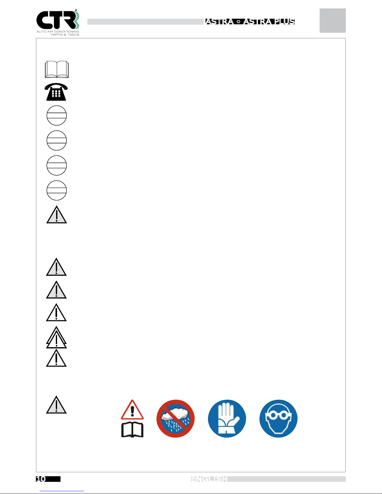
It is recommended to read through this use and maintenance manual before starting to use the unit and to
become knowledgeable with the controls.
In case of need, contact only our Technical Service Department (in particular for component repair and
replacement).
Do not perform any repair operations. If repair operations are performed by unexperienced staff, the safety levels
of the unit may be altered.
Do not place anything on the unit; the unit is neither a support surface nor a means of transport.
Never arrange the connection pipes (A/C system) and feed pipes in such a position that they may interfere or
can be damaged.
For refrigerant recovery do not use containers (pressurised) unsuited to the purpose, both in terms of material
and pressure level.
Always comply with the regulations in force regarding hygiene and safety in the workplace. Always follow the
instructions given on the safety sheet. Never leave the unit unattended in the workplace, even if it is set to
automatic mode.
3.1 Working environment
The unit should only be used by adults and responsible persons. Do not allow children to activate the control
device.
Do not approach the unit with open flames or anything else that may cause overheating (with consequent risk of
fire) of the refilling circuit. Do not use the unit in places where there is a risk of explosion or fire.
Do not smoke in the place where the unit operates.
Operate the unit in well lit places.
Always work in a well-ventilated environment. Operate and store the unit in a dry place protected from atmospheric agents (generally not in rough environmental conditions).
This manual contains essential safety rules for proper use of the unit: Wear safety goggles and gloves. Do not
expose to rain and direct sunlight. Read the owner’s manual of the vehicle to identify the type of refrigerant used
before using the unit.
Page 11
Instruction Booklet
11
ENGLISH
ASTRA • ASTR A PLUS
3.2 Preliminary checks
If the unit is turned off because of a power failure, wait about 10 seconds before restarting it, so that the electronic part can reset correctly.
The electrical/electronic parts must be collected separately and disposed of in accordance with applicable legislation.
3.3 USE
Pay particular attention to possible ejection of refrigerant, since:
- contact with the eyes may cause serious injury;
- contact with the skin (given the extremely low boiling temperature) may cause burns.
If refrigerant is ejected into your eyes or onto your skin, rinse with abundant water and immediately seek for
medical assistance.
The unit has been designed for use specifically with R134a refrigerant. The type of refrigerant (R134a) to be
used is specified on the specific label.
After turning on the unit, wait at least five minutes before performing any operation. If the processing cycle is
interrupted for any reason whatsoever (e.g. power failure) the operation must be resumed from scratch.
The external container used for refilling must be homologated for pressures of at least 35 bar and be
equipped with a safety valve (the valve must conform to the regulations for pressurised containers).
The refrigerant storage container must NEVER be filled to over 80% its total capacity to prevent drops in efficiency. Check filling of the oil containers during operation and make sure that they are not overfilled in order to
prevent sudden drops in efficiency. Do not use these containers with different types of substances.
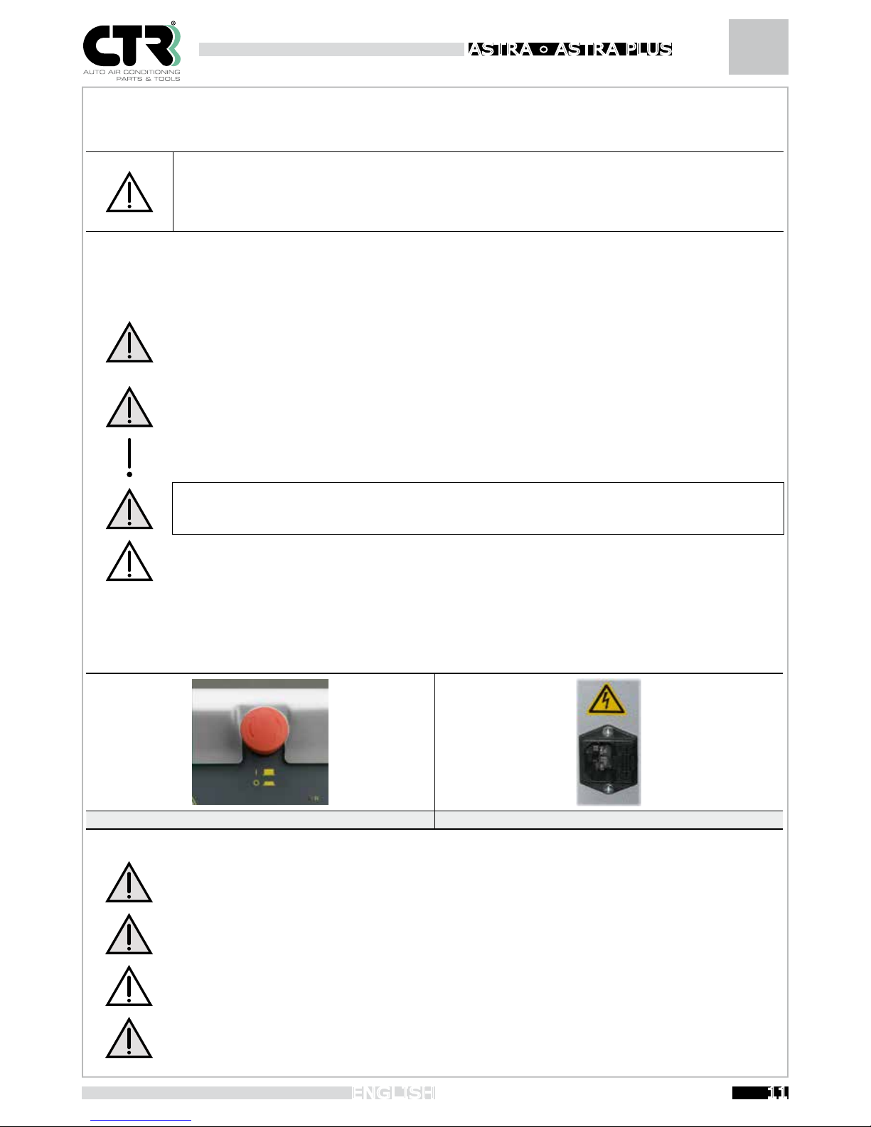
Live parts
MAIN/EMERGENCY SWITCH PLUG
The unit is to be used by one operator only. Any other persons must keep a safety distance both during operation
and during adjustment and maintenance.
Always connect the high and low pressure ducts (red and blue) with the parts provided and do not use them for
purposes different from those specified.
During operation, check the level in the oil tanks to prevent them from overflowing.
Never detach the HP and LP pipes if not specifically indicated in this manual. Do not activate the manual valves
during normal operation if not specifically indicated in the instructions.
Page 12
Instruction Booklet ASTRA • ASTR A PLUS
12
ENGLISH
3.4 Maintenance
Do not use, under any circumstances, flammable liquids or detergents to clean the unit.
Always wait a few minutes after turning off to allow the system to go into rest condition (temperature and pressure).
During maintenance operations, do not dispose of any residues in the environment, but comply with the regulations in force.
NEVER remove the cylinder unless specifically indicated.
Do not perform any repair or maintenance operations when the unit is running or connected to the mains.
Perform exclusively the maintenance and repair operations indicated in this manual. Operations performed by
unexperience persons will affect the overall safety level of the unit and expose the operator to serious risks.
3.5 Electrical power supply
The power supply of the unit must be connected according to the instructions of CTR S.R.L. , the company however, is not responsible for the connection. The safety of the unit is effective only when it is properly connected to an electric energy source that has
all the protections as required by the current applicable legislation (differential safety switch and earthing).
• The connection to the mains must be made using the plug provided with the unit, and a reduction used if necessary,
checking beforehand that the line voltage corresponds to that indicated on the label on the rear of the unit.
• In the event of damage, contact only our Technical Service Dept..
If the power plug needs to be replaced, contact our Technical Service Dept. and do not replace it unless written
permission has been given by our competent department. Failure to follow this instruction, will relieve CTR S.R.L.
of any responsibility for personal injuries or property damages caused by the power supply.
If using extensions, check that the cross-section of the cable is appropriate for its length and that it is positioned
in such a way that it cannot be damaged in any way (avoid walkable and wet areas).
Check that the point of connection to the electric energy source has all the protections as required
by the applicable legislation (earthing and differential switch).
Page 13
Instruction Booklet
13
ENGLISH
ASTRA • ASTR A PLUS
4. Handling and Transport
Before moving the unit, check that it is stable (check that the support surface is horizontal).
Before moving the unit, it is advisable to remove the parts installed after delivery in order to prevent damage
(see the Chapter Installation).
During this phase, it is recommended to:
- Correctly position all the accessories provided to prevent them from falling or being damaged during transport
- Move slowly and carefully to prevent possible instability
- Keep an adequate distance.
Be particularly careful when handling the unit in the workplace. In particular, avoid dips, steps or similar. If you
are not careful during transport, the adjustments made may not be correctly calibrated.
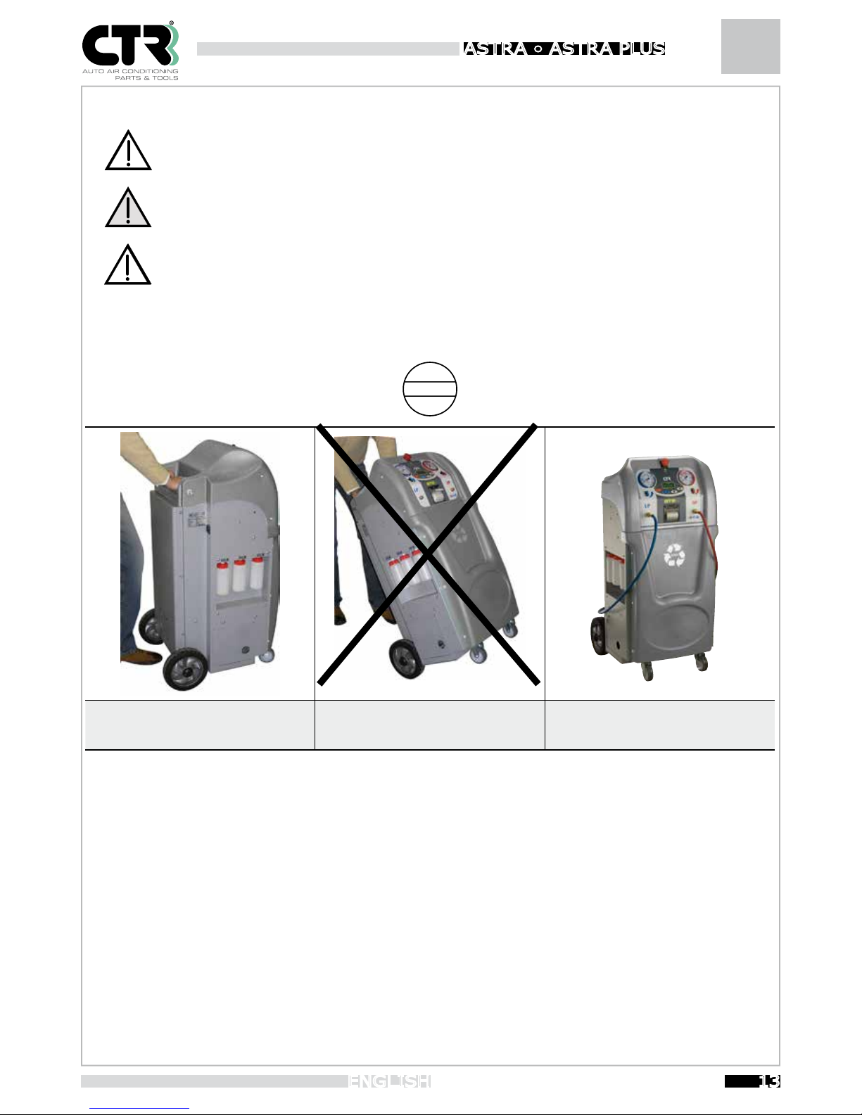
To transport the unit, use the wheels on the base
and push the unit by hand. Move only on at
surfaces.
To handle the unit, all the wheels must
touch the ground to prevent sideways lifting.
To lift the unit, use a lift truck of adequate capacity
for the weight of the unit (indicated in the technical
specications) using the pallet as support base.
Page 14
Instruction Booklet ASTRA • ASTR A PLUS
14
ENGLISH
5. General operating rules
5.1 Main panel
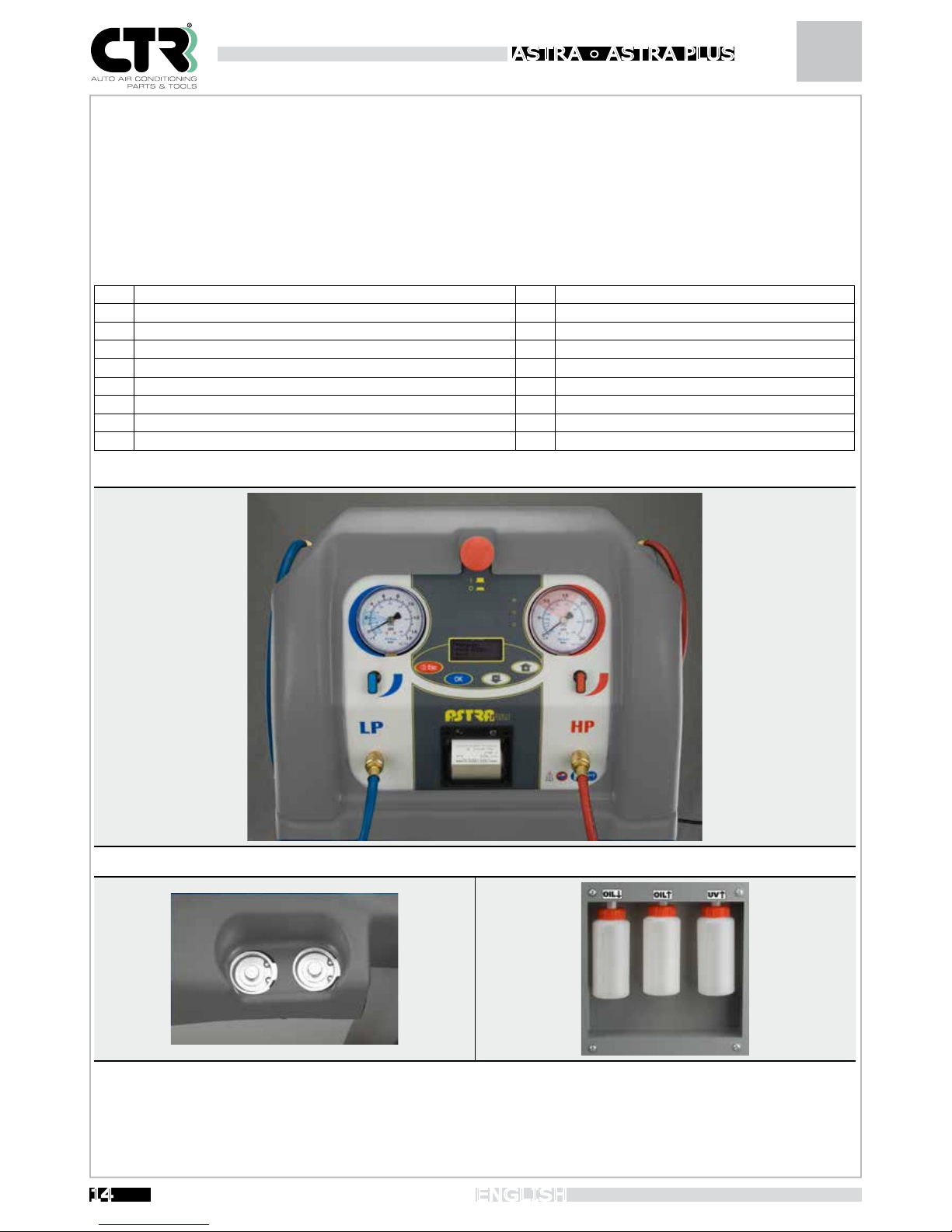
Described below is the control panel of the unit:
Description
1 Main/emergency switch 10 HP (high pressure) valve
2 Control panel 11 Used oil discharge tank
3 ON/OFF-ESC button 12 Oil filling tank
4 OK/Enter button 13 UV tracer charge tank
5 Forward/back/plus/minus buttons 14 High pressure connection
6 Cycle function LEDs: R=recovery V=vacuum C=charge 15 Low pressure connection
7 High pressure gauge (30 bar) 16 Refrigerant filters
8 Low pressure gauge (15 bar) 17 Printer
9 LP (low pressure) valve
1
2
3
4
5
6
8
7
9 10
11 12 13
14
15
17
16
Page 15
Instruction Booklet
15
ENGLISH
ASTRA • ASTR A PLUS
5.2 Operating phases
Described below are all the steps that the operator must follow to obtain an optimal result in absolute safety conditions, distinguishing between manual and automatic operation. To check proper functioning of the unit, there is an intelligent device which signals
any faults and warns the operator by means of error messages. An acoustic warning at the beginning of an operation indicates
that the set function has started in the correct condition, and a second acoustic warning indicates when the operation has been
completed.
Before performing the operations described below, to improve system efficiency (both in terms of energy and time) start the vehicle
engine and let the cooling system run for a few minutes so that the A/C system can reach full power, i.e. normal operating conditions.
If you have any doubts or other questions on use of the unit, please do not hesitate to contact our Technical
Service Dept. or an authorised Dealer.
During the refilling operations, there will be a certain quantity of refrigerant in the connection pipes. To drain the
pipes, follow the instructions given in the chapter Pipe draining procedure (pg. 5.8)..
At the end of the various phases there will be different residues in the containers. Adhere to the regulations in
force to dispose of them.
The recovery, vacuum and charging operations must be carried out with the vehicle and the system off (with the
power to the compressor cut).
5.3 Use
We advise you to carefully read through this manual for proper use of the unit.
Activation/deactivation:
- Connect the cable to the mains as described in the chapter “Electric power supply”.
- Enable the red mushroom button positioned on the control panel by turning it slightly to the right.
-
Hold the red ESC button pressed down for 2 seconds to turn the unit on and off. To cut the power to the unit, press the mushroom
button and cut the power to the disconnection switch (electrical socket of the unit).
- If the printer light is on and the rear electric fan is working, it means that the unit is powered.
Indications on the display:
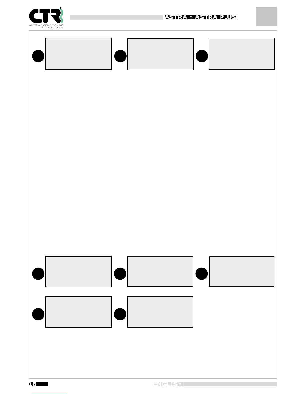
At power on the display appears for a few seconds as shown in Figure 1.
FW indicates the software version of the unit.
DB indicates the database version. Each time the SD card is updated, the version number automatically changes.
Fig. 2 shows the main menu listing the functions and the total quantity of gas in the cylinder.
Fig. 3, below the broken line, shows the data of the unit sensors during any function, while above the broken line, the data, times
and messages relating to the operation in progress (e.g. recovery).
Page 16
Instruction Booklet ASTRA • ASTR A PLUS
16
ENGLISH
1
FW : 0.0.01
DB : 0.0.01
2
GAS: 00,000 KG
> AUTOMATIC
RECOVERY
VACUUM
3
GASR: T:
- - - - - - - - - - - - - - - - G: 0.0.01 P: 0.0.01
T: 0.0.01 O: 00000
5.4 “AUTOM ATIC” operation
This function allows the system to perform the complete cycle, which is comprised of: recovery, recovered oil discharge, vacuum
phase, leak test, oil lling, UV tracer charge and refrigerant charge to restore the A/C system of the vehicle with the necessary
quantities of uids, using the SD card database of the unit, or by the operator entering the values.
The automatic cycle can be performed in two ways:
1- Automatic cycle through the database.
2- Automatic cycle by the operator.
The automatic cycle through the database allows the unit to perform all the operations using the rst-installation information
contained in the memory card.
The automatic cycle by the operator allows executing all the operations with the operator selecting the values of the uids to be
recharged.
AUTOMATIC CYCLE EXECUTION THROUGH THE DATABASE
- Connect the high and low pressure pipes to the A/C system
- Open the HP and LP valves, or if there is only one service point, open the corresponding valve.
- Select “AUTOMATIC” with the “+ ↑” e “- ↓ ” buttons. Press OK to start the cycle.
Move in the database using the up “+ ↑” e down “- ↓ ” arrows to select the model involved and press the OK button. To go back,
press the ESC button for 2 sec.
Select the brand (Fig.1), select the model (Fig.2), select the equipment (Fig.3), view the quantity of fluids and oil viscosity (Fig.4),
then press OK to confirm. Move the cursor “>” (Fig.5) to UV if you want to add the tracer or to “Start cycle” to start the operation.
1
MANUAL
> ALFA
AUDI
BMW
2
> 147
156
159
GT
3
> 2.0 JTS
1.9 JTD
1.8 JTD 16V
3.2 GTA
4
GAS : 500 g
OIL : 21 g
ISO 46
5
GAS : 500 g
OIL : 21 g
UV : NO
> Start Cycle
Page 17
Instruction Booklet
17
ENGLISH
ASTRA • ASTR A PLUS
-
Once the cycle has been started and conditions permitting, the system performs the cycle, showing all the current
phases on the
display with values and text messages. The vacuum time is automatically calculated.
-
In the event of an error, the display shows the relative message and activates an acoustic signal. To exit press the
ESC button for
2 sec.
- Press the ESC button for 2 seconds during the operation to return to the main menu.
- in the event of an emergency, press the red mushroom button on the control panel to completely turn off the unit; in this case,
the function that was in progress will not be stored.
- When the cycle has been completed, press the ESC button for 2 sec. to exit
- When you exit the operation you will be prompted to print the report. Press OK to print or ESC to return to the main menu.
-
After charging with refrigerant , the unit checks for any air in the cylinder. If air is detected, the system activates
discharge for a few seconds showing the message “Discharging non-condensable gases”. The discharge pressure may vary
between 5 and 16 bar. There are 3 LEDs (light emitting diodes) that indicate the cycle in progress. At the end of the cycle,
the LED will remain lit to indicate the completion of the cycle.
!
Warning: the quantity of UV tracer required for the correct contrast depends on the nature of the product. The value indicated
under UV refers to contrast products sold by CTR
S.R.L.
AUTOMATIC CYCLE BY THE OPERATOR
- Connect the high and low pressure pipes to the A/C system
- Open the HP and LP valves, or if there is only one service point, open the corresponding valve.
- Select “AUTOMATIC” with the “+ ↑” e “- ↓ ” buttons. Press OK to start the cycle (Fig.1)
1
> MANUAL
ALFA
AUDI
BMW
5
GAS : 500 g
OIL : 30 g
UV : NO
> Start Cycle
- When the “Manual” option is selected, the fluids being charged are directly shown: GAS-OIL-UV with fixed values of 500 g,
30 g, and 7 g. You can also change the suggested values (Fig. 5) as desired in the “Customisation” option in the
SERVICE menu.
- Move the cursor “>” to “Start cycle” and press OK to start the operation. If conditions permit, the system executes
the cycle, showing all the current phases on the display with values and text messages. The vacuum time is automatically
calculated.
Changing the fluid quantities
To change a quantity, move the cursor “>” to the item involved (Fig.5), press OK to select it and use the “+ ↑ ” and “- ↓ ” buttons
to change the value. Changes are made in quantities of 5 g for gas and 1 g for oil. To disable an item, set the value to zero.
The item “UV” is activated with “YES” and deactivated with “NO” pressing the OK button to confirm. If you select “YES”, the quantity
of tracer is fixed at 7 g, sufficient for up to 1.3 kg of refrigerant; if you select “NO”, no tracer will be charged.
Page 18
Instruction Booklet ASTRA • ASTR A PLUS
18
ENGLISH
After charging with refrigerant , the unit checks for any air in the cylinder. If air is detected, the system activates discharge for a
few seconds showing the message “Discharging non-condensable gases”. The discharge pressure may vary between 5 and 16 bar.
There are 3 LEDs (light emitting diodes) that indicate the cycle in progress. At the end of the cycle, the LED will remain lit to indicate
the completion of the cycle.
! Warning: the quantity of UV tracer required for the correct contrast depends on the nature of the product. The value indicated
under UV refers to contrast products sold by CTR
S.R.L.
Procedure to empty pipes
- (View paragraph 5.8).
5.5 “RECOVERY” operation
This function allows drawing all the refrigerant from the system and making it reusable by means of a complete ltering and
distillation process.
- Connect the high and low pressure pipes to the A/C system
- Open the HP and LP valves, or if there is only one service point, open the corresponding valve.
- Select RECOVERY with the “+ ↑” and “- ↓ ” buttons.
Press OK to start the recovery cycle of the refrigerant in the circuit. During this operation, the display shows the general parameters,
and “GasR:” indicates the gas recovered and the time it took. There is a pause in the recovery phase when the pressure reaches
- 0.10 bar. (value controlled by the pressure sensor). The LED R (recovery) stays on for the entire duration of the cycle.
- This period lasts about 4 min , including old oil discharge, in order to allow any refrigerant that has remained blocked in the low
pressure and temperature A/C system to change into the gaseous state to be recovered. This phase is signalled by an increase
in the pressure indicated on the display under the item “P:” (pressure read by the sensor). After the pause, if the pressure has
increased, repeat the function a maximum of three times, while when there is no pressure end the cycle.
-
Pess the ESC button for 2 seconds during the operation to exit the phase and return to the main menu. In this case, you will not
be prompted to print the report.
- In the event of an emergency, press the red mushroom button on the control panel to completely turn off the unit; in this case,
the function that was in progress will not be stored.
- When the cycle has been completed, press the ESC button for 2 sec. to exit
- When you exit the operation you will be prompted to print the report. Press OK to print or ESC to return to the main menu.
-
All the refrigerant recovered in this operation increments a recovery counter to monitor the life of the filters; when a total of 150 kg
has been reached, a message will appear on the display warning you that the filters need to be replaced. The counter increments
by grams with resolution of 3g.
- In the event of an error, the display shows the relative message and activates an acoustic signal. To exit press the ESC button
- The time available for the operation is 30 min.
The old oil container must always be empty to prevent leaks.
Page 19
Instruction Booklet
19
ENGLISH
ASTRA • ASTR A PLUS
5.6 VACUUM” operation
This function allows the moisture in the system to evaporate by means of a pump that generates a high degree of vacuum.
- Connect the high and low pressure pipes to the A/C system.
- Open the HP and LP valves, or if there is only one service point, open the corresponding valve.
- Select VACUUM with the “+ ↑” and “- ↓ ” buttons.
- Press OK to start the cycle. The display shows the vacuum time, currently set to 30 min. Use the “+ ñ ” and “- ò“
buttons to change the value between 05 and 95 min. You can also change the vacuum time value as desired
in the “Customisation” option in the SERVICE menu.
- Press OK to continue with this function. Before starting the vacuum, the unit runs a check of the starting conditions with the
“vacuum preparation” phase, the microprocessor briefly opens the solenoid valves, and based on the conditions acquired, inde
pendently decides how to proceed. There may be various combinations, among which activation of recovery and
oil discharge, also simultaneously with the vacuum.
-
When the vacuum pump has started, the message changes to “Waiting for pressure level” waiting to reach the vacuum
pressure
(-0.75 bar) counting down the time set. When the level has been reached, the “Vacuum cycle” starts followed by the
remaining time. The LED V (vacuum) stays on for the entire duration of the cycle.
- Press the ESC button for 2 seconds during the operation to return to the main menu.
-
In the event of an emergency, press the red mushroom button on the control panel to completely turn off the unit;
in this case,
the function that was in progress will not be stored.
- When the set time has run out, a leak test is run for 5 min., and the progress bar shows the remaining time
at the end of the phase. If a leak is detected (-0.75 bar) the error message is shown on the display followed by an acoustic
signal.
- When the cycle has been completed, press the ESC button for 2 sec. to exit
- When you exit the operation you will be prompted to print the report. Press OK to print or ESC to return to the main menu.
- The vacuum pump operating time increments a vacuum hour counter to monitor when oil change is due.
When 200 hours of operation have been reached, you will be warned to change the oil. The counter increments in seconds.
- In the event of an error, the display shows the relative message and activates an acoustic signal. To exit, press the ESC button
for 2 seconds.
5.7 “CHARGE TO VEHICLE” operation
This function allows you to charge the system with refrigerant, oil and UV tracer in the correct quantities.
Absolutely do not mix different types of lubricants. Always check the types of oil to be used in the different A/C
systems (according to the type of compressor used), which can be found on the technical specification sheets.
- Connect the high and low pressure pipes to the A/C system
- Open the HP and LP valves, or if there is only one service point, open the corresponding valve.
- Select “CHARGE TO VEHICLE” with the “+ ↑” and “- ↓ ” buttons. Press OK to start the cycle (Fig.1)
Page 20
Instruction Booklet ASTRA • ASTR A PLUS
20
ENGLISH
1
GAS: 00,000 KG
VACUUM
> CHARGE TO VEHICLE
RECHARGE CYLINDER
SERVICE
2
> MANUAL
ALFA
AUDI
BMW
5
GAS : 500 g
OIL : 30 g
UV : NO
> Start Cycle
- Once you have selected “CHARGE TO VEHICLE”, you can select to continue in two ways (Fig.2):
1- Charge through the database
2- Manual charge
- Charging through the database allows you to use the rst-installation oil and gas values on the memory card, selecting the
vehicle.
-
Manual filling allows the fluid values selected by the operator to be set. The GAS-OIL-UV values are fixed at 500 g, 30 g and 7 g.
You can also change the suggested values (Fig. 5) as desired in the “Customisation” option in the SERVICE menu.
- To disable an option, set the value to zero, or select “NO” for the UV tracers.
Caution: to fill the system with oil and UV tracer, it must be in vacuum mode, otherwise an error will be signalled
and the cycle locked. When the vacuum is low, the cycle may activate but then lock when the pressure difference
levels out.
- Move the cursor “>” to “Start cycle” and press OK to start the operation. If conditions permit, the system executes
the cycle, showing all the current phases on the display with values and text messages.
-
“GasC:” indicates the quantity of gas remaining to be charged and the time it takes. The LED C (charge) remains lit for the entire
duration of the cycle.
- In the event of an error, the display shows the relative message and activates an acoustic signal. To exit press the ESC button.
- Press the ESC button for 2 seconds during the operation to return to the main menu.
-
In the event of an emergency, press the red mushroom button on the control panel to completely turn off the unit;
in this case,
the function that was in progress will not be stored.
- When the cycle has been completed, press the ESC button for 2 sec. to exit
- When you exit the operation you will be prompted to print the report. Press OK to print or ESC to return to the main menu.
-
The unit controls the quantity charged so that it does not go below the minimum level of 1 kg, thus allowing you
to fill the system
with any quantity higher than 1 kg (e.g. the display indicates 1300 g, so you can charge 300 g).
After charging with refrigerant , the unit checks for any air in the cylinder. If air is detected, the system activates discharge for a
few seconds showing the message “Discharging non-condensable gases”. The discharge pressure may vary between 5 and 16 bar.
!
Warning: the quantity of UV tracer required for the correct contrast depends on the nature of the product. The value indicated
under UV refers to contrast products sold by CTR
S.R.L.
Changing the fluid quantities
To change a quantity, move the cursor “>” to the item involved (Fig.5), press OK and use the “+ ↑ ” and “- ↓ ” buttons to change
the value. Changes are made in quantities of 5 g for gas and 1 g for oil. To disable an item, set the value to zero.
The item “UV” is activated with “YES” and deactivated with “NO” pressing the OK button to confirm. If you select “YES”, the quantity
of tracer is fixed at 7 g, sufficient for up to 1.3 kg of refrigerant; if you select “NO”, no tracer will be charged.
Page 21
Instruction Booklet
21
ENGLISH
ASTRA • ASTR A PLUS
5.8 Pipe draining procedure
1. When the procedure has been completed, keep the high and low pressure pipes connected, close the HP and LP valves, start the
vehicle engine and wait a few minutes for the A/C system to reach full power.
2. If there is only one service point, close the HP or LP valve used and disconnect the pipe from the vehicle.
3. If there are two service points, disconnect the high pressure pipe (HP) from the vehicle and open the HP and LP valves to allow
the gas contained in the pipes to return through the low pressure in the vehicle. Wait until the high and low pressures drop to a value
of about 2 bar, then also disconnect the low pressure pipe (LP).
4. Stop the engine.
This phase must be executed with the engine on, The other phases strictly with the engine off.
5.9 Refrigerant topping-up
If there is refrigerant in the A/C system, the only way to fill the systen with more gas is to perform a TOP-UP operation. To execute
this phase, connect the unit to the A/C system, start the vehicle engine and wait a few minutes for the A/C system to reach its
operating power and stabilize.
- Connect the low pressure pipe.
- Start the engine and the A/C system
- Partially open the low pressure valve (LP)
- Select the “FILLING” operation and press OK to start the cycle.
- Select “GAS”, set the desired quantity and then press OK.
- Select “OIL” , set the quantity to zero and then press OK.
- Select “UV” and “NO”
- Select “START CYCLE” and press OK.
- When charging has been completed, close the LP valve, stop the A/C system and the engine.
This phase must be executed with the engine on, The other phases strictly with the engine off.
Page 22
Instruction Booklet ASTRA • ASTR A PLUS
22
ENGLISH
5.10 “RECHARGE CYLINDER” operation
This function is used to ll the internal cylinder with refrigerant. Filling is set to 7 kg on a total of 10 for Astra and 16 kg on a total
of 18 for Astra Plus, in order to always have a good charge range and sufcient volume to perform the recovery operations.
Use the red high pressure pipe HP; remove the quick-coupling at its end; connect the pipe to an external cylinder containing
refrigerant. If the external cylinder is not equipped with an internal plunger, it must be held upside down so that the
gas can always ow out in the liquid state.
- Open the cylinder and the HP valve.
- Select the option “Recharge cylinder” with the “+ ↑” and “- ↓ ” buttons. Press OK to start the cycle.
- The display shows the “Estimated charge:” in grams of the quantity of refrigerant required to completely fill the cylinder
with an approximation of 200g. You can also change the maximum filling value as desired in the “Customisation”
option in the SERVICE menu.
- Press OK to continue with this function. During this operation, the display shows the general parameters, and “GasR:” indicates
the gas recovered and the time it took The unit adapts its recovery capacity in relation to the pressure coming from the external
cylinder. Just before reaching the estimated value, operation is locked, the acoustic signal is activated and the message “Close
cylinder and press OK” appears on the display in order to arrive at the calculated value without pressure residues in the unit.
- Press the ESC button for 2 seconds during the operation to return to the main menu.
- In the event of an emergency, press the red mushroom button on the control panel to completely turn off the unit; in this
case, the function that was in progress will not be stored.
- When the cycle has been completed, press the ESC button for 2 sec. to exit
- During this cycle, the filter counter does not increment.
-
In the event of an error, the display shows the relative message and activates an acoustic signal. To exit press the ESC button.
This operation does not increment the filter counter.
6. “SERVICE” menu
6.1 Service menu for the operator
The basic settings allow the unit to start operating immediately, in all the operating phases.
- This menu contains all the functions necessary for optimal use and customisation of the unit
Select the SERVICE option from the main menu with the “+↑ ” and “- ↓ ” buttons and press OK”.
- “View parameters”. By accessing this option, all the current values of the unit sensors are displayed with the relative
symbols: G: Kg gas in cylinder; P: bar value of the pressure sensor positioned after the HP and LP valves; T: °C of the cylinder
temperature sensor; O: grams of fresh oil; UV: grams of tracer. Press ESC for 2 sec. to exit.
- “Replace lters”. Use this function when the cartridge lters need to be replaced (see routine maintenance).
- “Recovery counter”. This option shows the kg of refrigerant gas recovered. This is shown by the partial counter, that
automatically resets after changing the lters, and the total counter, that follows the life of the unit and cannot be reset.
- “Vacuum pump hours”. This option shows the hours of operation of the vacuum pump. This is shown by the partial
counter, that follows the oil changes, and the total counter, that follows the life of the unit and cannot be reset (see routine
maintenance).
Page 23
Instruction Booklet
23
ENGLISH
ASTRA • ASTR A PLUS
- “Compressor hours”. This option displays the hours of operation of the recovery compressor.
- “Select language ”. This option allows you to select one of the available languages. Use the “+↑ ” and “- ↓ ” buttons to
move the cursor “>” to the desired language, press OK and wait 10 seconds for the new setting.
- “Customisation ”. This option allows you to modify the suggested values in the various operations relating to: gas quantity
with variations of 5 g, oil quantity with variations of 1 g, tracer quantity with variations of 1 g, vacuum time with variations of 5
min. and cylinder full with variations of 5 g. The Default option resets all the values to the manufacturer’s setting.
6.2 Service menu for technical staff
This section of the menu is only for technical service staff authorised by CTR S.R.L.
- “Cylinder calibration”. This option allows you to calibrate the gas scale.
Before proceeding, carefully read the following:
- Disconnect the unit from the mains.
- Remove the front panel.
- Remove the rear panel.
- Connect the unit to the mains. Do not touch anything on the inside unless specifically indicated in this cha ter. Risk of electrocution.
Before starting the calibration procedure, completely empty out the cylinder of the unit using a second recovery
unit, in order not to pollute the environment with refrigerant.
If you do not have a second recovery unit, do not continue with the operation!
- The phases of this cycle are divided into: discharging the refrigerant from the cylinder, vacuum in the cylinder and calibration.
- Connect the second recovery unit to the HP connection of the unit, open the red valve and press OK to discharge the refrigerant
from the cylinder.
- When the cycle has started, the display shows the message “Cylinder calibration. Waiting for pressure level …Please wait…” until
the cylinder is completely empty.
Recover the refrigerant with the second unit through the HP valve. When the set pressure level has been reached, the message
changes to “Cylinder calibration. Close HP-LP”. Disconnect the second unit, close the HP valve and press OK to go to the vacuum
phase, indicated with “Cylinder calibration. Vacuum cycle …Please wait…”. When the necessary time has elapsed, you go to “Cylinder
calibration”. Gently press OK; the progress bar scrolling indicates that the procedure is being run properly. A new message will ask
you to remove the cylinder and press OK. Undo the 4 screws (Astra) or the 4 nuts (AstraPlus), lift the cylinder making sure that the
scale does not touch the cylinder, wait a few seconds and then press OK to conrm; the progress bar scrolling indicates that the
procedure is being run properly. If the cycle has not been performed successfully, you will be unable to exit the calibration procedure.
You must therefore repeat it from scratch. If the cycle has been performed successfully, press ESC to return to the main menu. Fasten
the cylinder to the scale with the screws/nuts previously removed.
- “Oil calibration”. This option allows you to calibrate the oil scale. For this phase you need a sample weight of 500 g.
Before proceeding, check that the container is completely empty (central container). Press OK to continue and ESC to exit. The
display shows the message “Charge 500 grams”; position the sample weight so that it is in contact only with the container (which
must remain mounted). Wait a few seconds for it to stabilise and press OK; the progress bar will indicate when the procedure has
been completed. The message changes to “Remove weight”, therefore, remove the sample weight and wait a few seconds for it
Page 24
Instruction Booklet ASTRA • ASTR A PLUS
24
ENGLISH
to stabilise and then press OK. When the progress bar is complete, if the cycle has not been performed successfully, you will be
unable to exit the calibration procedure. You must therefore repeat it from scratch. If the cycle has been performed successfully, the
message “End of cycle” will be displayed; press ESC to return to the main menu.
- “UV calibration”. This option allows you to calibrate the UV scale. For this phase you need a sample weight of 500 g. Follow the
same instructions as given for oil calibration (right-hand side container).
- “Press calibration”. This function allows you to calibrate the pressure sensor. Press OK to start the cycle. The display will read
“Set atm. pressure and press OK”; remove High and Low service hoses, open the HP and LP manual valves in the front panel of
the refill unit, press OK to confirm (ESC to exit). When the progress bar is complete, the new message “Close HP and LP and press
OK” will be displayed; close the HP and LP manual valves in the front panel of the refill unit and press OK to continue (ESC to exit).
The vacuum pump starts and when the cycle is successful completed, the message “End of cycle” will be displayed; press ESC to
return to the main menu.
7. Refrigerant transfer from the unit to an external container
To drain the cylinder, perform the following operations:
- Turn on the unit, connect the HP pipe to a cylinder or another external container prepared to collect the refrigerant and open the
valves on the connection line.
-
Select “CHARGE TO VEHICLE”, set the quantity of gas you want to transfer, set the oil to zero, set “UV” to NO, move the cursor to
“Start cycle” and press OK.
- When the transfer phase has been completed, close the valves and recover the residual pressure in the pipe.
8. Routine maintenance
1
2
3
4
5
6
8.1 Refrigerant filter replacement:
The innovative refrigerant cartridge filters have also allowed a technological evolution in the maintenance process. This unit is
equipped with an electronic system that is capable of automatically performing all the phases required for filter replacement, ensuring full safety for the operator without the help of technical staff.
When the filter counter has reached a calculated value of refrigerant recovered from vehicles, a message prompting the operator
to replace the filters is displayed for a few seconds upon activation. Before continuing, order the new filters from the CTR S.R.L.
sales network.
Page 25
Instruction Booklet
25
ENGLISH
ASTRA • ASTR A PLUS
- Always replace both the filters each time the “Replace filters” message is displayed.
- Use only dedicated original spare parts. There are no compatible filters on the market.
- The “Replace filters” message warns you when the filters need to be replaced, but does not in any way lock
unit operation . If you ignore the “Replace filters” message and continue using the unit, you may irreparably
compromise proper functioning of the unit and forfeit the warranty because of improper use.
- Check that the old oil container is empty.
- Select the “SERVICE” option from the main menu.
- Move the cursor to “REPLACE FILTERS”.
- Close the HP and LP valves as shown on the display.
-
Press the OK button. The electronic system activates a procedure to release the pressure from the filters and, when this has been
completed, the message “REPLACE FILTERS” will be shown on the display. Do not turn off the unit.
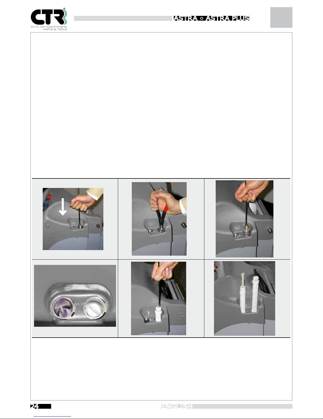
- Insert the appropriate remover and press firmly downwards. (Fig. 1)
- Remove the snap rings seeger rings. (Fig. 2)
- Remove the filter caps with the dedicated extractor provided (Fig. 3-4). Check the condition of the O-rings and replace them if
necessary.
- Remove the cartridges with the extractor using the other end (Fig. 5).
- Fit the new cartridges, respecting the fitting direction (Fig. 6).
- Follow the procedure in reverse order to close the cartridges.
- Only after having closed the caps, press “OK” to continue the procedure.
The unit automatically performs the dehumidification procedure, a leak test, gas recycling in the cylinder, and finally resets the
partial counter (recovery counter) and the service message. If there are any problems, an error message is displayed and the
operation blocked.
The time required for the entire operation is approx. 30min.
8.2 Vacuum pump replacement:
The life of the vacuum pump is monitored by the electronic system in order to always ensure optimal efficiency and a long life in
normal operating conditions. When the service message “Change vacuum pump oil” is displayed, proceed as follows:
When topping up or changing the oil in the vacuum pump, use specific oil for vacuum pumps.
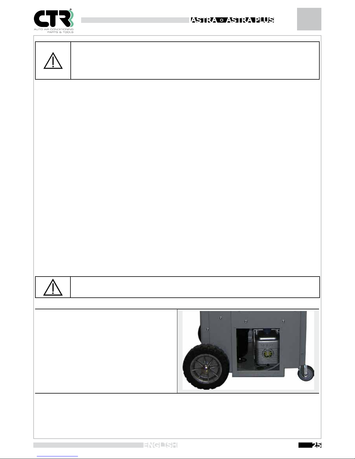
To top up (see figure), unscrew the bleeding (A) cap and pour
in oil until it reaches mid-level of the sightglass (C); when
done, screw the bleeding cap back on.
To change the oil:
- Run the pump for 10 minutes
- disconnect the unit from the power supply
- Remove the drain plug positioned in the lower part of the
pump (B);wait until all the oil has drained out Refit the drain plug
-
Unscrew the bleeding cap and pour in new oil until it reaches
mid-level of the sightglass. Screw the bleeding cap back on.
When the message “Change vacuum pump oil” is displayed, ESC and OK will appear under the item “Vacuum pump hours” in the
SERVICE menu. After changing the oil , press OK to reset the partial counter.
B
A
C
Page 26
Instruction Booklet ASTRA • ASTR A PLUS
26
ENGLISH
9. Oil/UV tracer containers
The unit is supplied with two containers to charge the system with oil and UV tracer. Should it be necessary during operation to use
different oils, use different containers, one for each type of oil.
Absolutely do not mix different types of lubricants. Always check the types of oil to be used in the different A/C
systems (according to the type of compressor used), which can be found on the technical specification sheets.
9.1 Service pipes
The unit is provided with 2.5 m long pipes for connection to the A/C system.
Should these pipes not be long enough for operating or functional requirements, 3-6 m long pipes are available at our sales point.
9.2 Spare parts
All the spare parts for ASTRA-ASTRAPLUS are sold by CTR S.R.L. and can be ordered at our sales points.
9.3 Adhesive labels
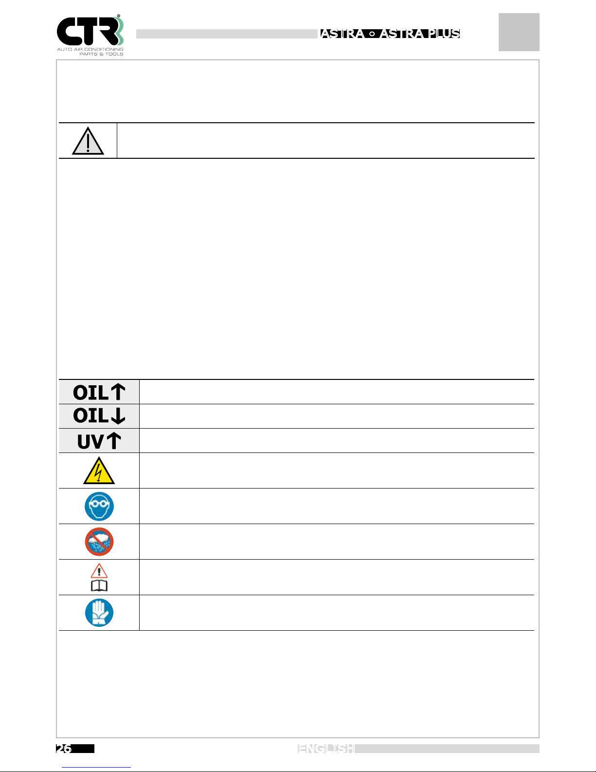
Explained below is the meaning of the adhesive labels used:
Indicates the container for fresh oil charge.
Indicates the container for old oil discharge.
Indicates the container for UV tracer charge.
Indicates that there are high-voltage parts with the risk of electrocution
Wear safety goggles. Contact with the eyes may cause serious injury.
Operate and store the unit in a dry place protected against atmospheric agents.
Read the owner’s manual of the vehicle to identify the type of refrigerant used before using the unit.
Wear protective gloves. contact with the skin (given the extremely low boiling temperature) may cause
burns.
Page 27
Instruction Booklet
27
ENGLISH
ASTRA • ASTR A PLUS
10. SD card database update
The vehicle database resides on the removable SD card housed on the circuit board of the unit.
This operation may only be carried out by technical service staff authorised by CTR S.R.L.
Contact your local Dealer.
11. Printer
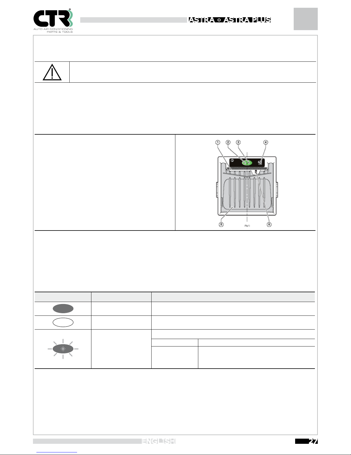
1- Paper feed slot
2- Status LED
3- OPEN button for paper roll compartment
4- Paper FEED button
5- Paper roll compartment
6- Out-of-paper sensor (internal)
The green status LED indicates the hardware status of the printer. In the event of malfunctioning, the LED ashing frequency will
change according to the following table.
Status LED Colour Description
OFF Printer off
ON
Printer on: no error
FLASHING
RECOVERABLE ERROR
Slow Out of paper
Fast
Print head overheating
Incorrect supply voltage
Page 28
Instruction Booklet ASTRA • ASTR A PLUS
28
ENGLISH
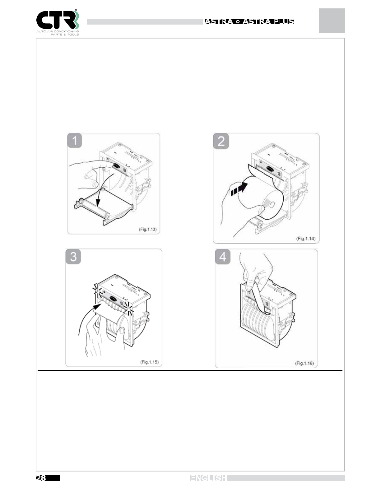
To change the paper roll, proceed as follows:
1- Open the printer cover by pressing the OPEN button (see Fig.1.13).
2- Position the paper roll in the compartment, respecting the rotation direction indicated (see Fig.1.14).
3- Pull the paper until it comes out of the compartment and close the cover (see Fig.1.15). The cover locks.
4- Tear off the excess paper using the serrated edge (see Fig.1.16).
5- The printer is now ready for printing.
Page 29
Instruction Booklet
29
ENGLISH
ASTRA • ASTR A PLUS
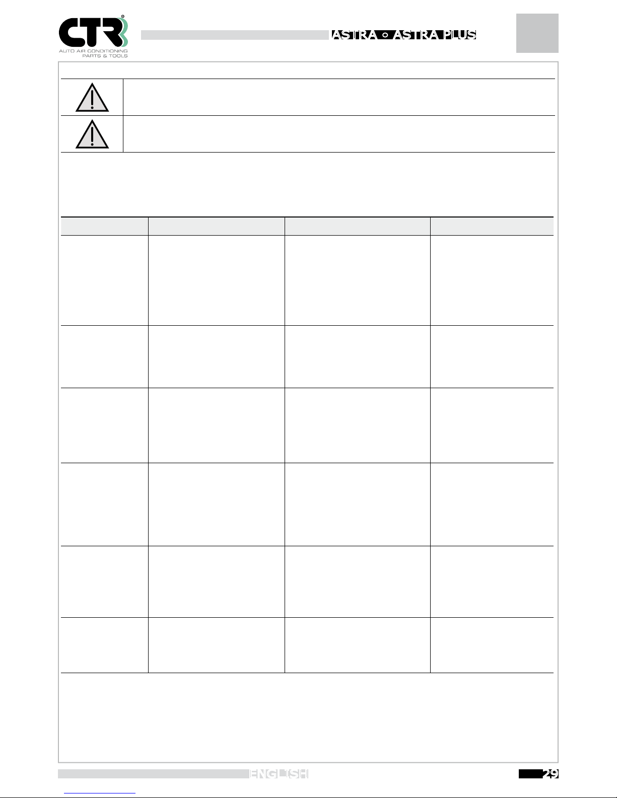
12. Troubleshooting
To perform repair, maintenance or adjustment operations not described in the above chapters, contact skilled
staff only. Failure to follow this instruction will relieve CTR S.R.L. of any responsibility for unit malfunctioning.
The table indicates the persons that need to perform the operation. Strictly follow the instructions given.
After solving the problem following the instructions, the phases you were executing can be repeated from scratch.
Problem Causes Remedies Operation
The machine does
not work
1) Repeated turning on and off
2) External unit fuses blown
3) Internal unit fuses blown
1) Turn off the machine and wait
at least 10 sec. before restarting it
2) Replace
3) Replace
1) Operator
2) Operator
3) Technical staff
The unit does not
recover
1) Fuse blown
2) Recovery compressor damaged
1) Check the integrity of the recov-
ery compressor/solenoid valve fuse
on the circuit board
2) Replace the compressor
1) Technical staff
2)Technical staff
The vacuum pump
does not work
1) Gas in the circuit
2) No power to the pump
3) Vacuum pump damaged
1) Execute a recovery phase
2) Check the electric power supply
and the fuses
3) Replace the pump
1) Operator
2) Technical staff
3) Technical staff
The vacuum timer
does not start but
the pump works and
the pressure gauges
indicate -1 bar
1) Pressure sensor out of
calibration
2) The pump is not running
1) Calibrate the pressure sensor
(see Service menu).
2) Check the integrity of the vacu-
um pump fuse on the circuit board.
1) Operator
2) Technical staff
A leak is always indicated after the leak
test
1) Pressure sensor out of
calibration
2) Sediment in the vacuum solenoid valve
1) Calibrate the pressure sensor
(see Service menu).
2) Remove the sediment
1) Operator
2) Technical staff
The unit does not
charge the refrigerant
1) The charge solenoid valve does
not open
2) The one-way valve is locked
1) Check the integrity of the sole-
noid valve fuse
2) Replace the valve
1) Technical staff
2) Technical staff
Page 30
Instruction Booklet ASTRA • ASTR A PLUS
30
ENGLISH
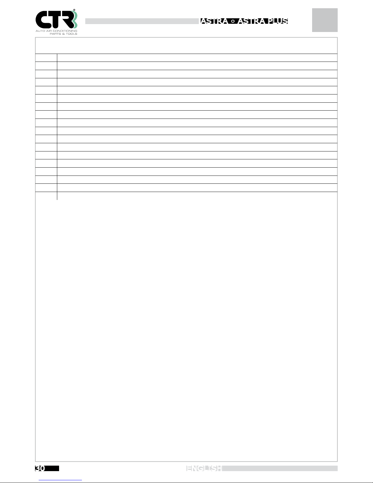
ASTRA – ASTRA PLUS ERROR MESSAGES
E0 Full cylinder .
E2 Recovery time ended.
E3 Refrigerant presence at the beginning of vacuum phase.
E4 Vacuum time ended. It is not possible start up vacuum timer.
E5 Leak presence during vacuum control.
E6 Not enough refrigerant into cylinder.
E7 Refrigerant charge time ended .
E8 Max pressure inside circuit .
E9 Not enough oil for charging.
E10 UV tracing not enough for charging.
E11 There is not refrigerant to recover.
E12 Olio or UV charge is not possible because of low pressure/ not enough vacuum into A/C system
E13 Olio UV charge time ended.
E20 Refrigerant scale broken.
E21 Oil scale broken.
E22 UV scale broken.
E23 Pressure sensor broken.
E24 Temperature sensor broken or external temperature is lees than 2°C.
Page 31
Instruction Booklet
31
ENGLISH
ASTRA • ASTR A PLUS
Page 32
Instruction Booklet ASTRA • ASTR A PLUS
32
ENGLISH
Page 33
CTR S.R.L. would like to thank you for buying a product from its range and invites you to read this manual. Inside this
manual you will find all the information you need for correctly using the unit; please follow the instructions contained
in this manual carefully and read through every section. You should also store the manual carefully to keep it in good
readable condition. The content of this manual may be modified without prior notice, nor further obligations, in order
to include changes and improvements to the instructions already provided. No part of this manual may be reproduced
or translated without prior written consent of the owner. CTR S.R.L. shall be responsible for any manufacturing defect
that may arise during the entire warranty period and undertakes to correct any defect as promptly as possible.
WARRANTY
The warranty is valid for 12 months from the date of purchase. The warranty covers only the replacement of faulty
parts. The warranty shall be invalidated if the equipment is found to have been improperly used or tampered with by
people not authorized by us or if nonconforming components or techniques have been used.
LABELLING
Model
ASTRA PLUS
CTR S.R.L.
via T. ed E. Manzini,9
43126 PARMA - ITALY MADE IN ITALY
Refill machine
Model:
ASTRA PLUS
Power Supply Voltage / Frequency
Serial Number Max. absorbed Current (A) Max Power (W)
Max. Working Pressure Min. Working Temperature. Max. Working Temperature
Refrigerant
R134a
Production Year
Category of risk
2014/68/UE
Group Fluid 2 CAT.
II
This label is merely indicative. The complete data label is affixed onto the unit.
Page 34
DECLARATION OF CONFORMITY
Directive 2006/42/CE “Machine Directive”
Directive 2014/30/UE “Electromagnetic Compatibility Directive”
Directive 2014/35/UE “Low Voltage Directive”
Directive 2014/68/UE “PED European Directive”
We: CTR S.R.L. Via T. ed E. Manzini n° 9, 43126 Parma (Italy) represented by its Legal Representative, declare on our sole
responsibility that the product:
Refill machine
Model: ASTRA PLUS
complies with the requirements of directive 2006/42/CE, 2 0 1 4 /30/UE an d 2014/35/UE and associated implementation provisions.
Moreover the following technical standards have been applied:
• EN 61000-6-3: 2007 + A1:2011 – Electromagnetic compatibility (EMC). Part 6-3: Generic standards – Emission standard
for residential, commercial and light-industrial environments.
• EN 61000-6-2:2006 – – Electromagnetic compatibility (EMC) Parte 6-2: Generic standards – Immunity for industrial
environments.
At last the pressure circuit complies with directive 2014/68/UE as amended, and it is classified respectively:
• category II for the Astra Plus model.
We hereby specify that the maximum permissible limits for correct operation of the Astra Plus unit are:
• Maximum working pressure: 16 bar
• Maximum working temperature: +50°C
• Minimum working temperature: +5°C
We also point out that:
• the year of manufacture is indicated on the label (with CE marking) affixed onto the unit;
• the technical construction file is kept at our company by the legal representative.
The product has been certificated by the ICEPI S.p.A. Notified Body.
COMPONENTS INCLUDED IN THE PRODUCT
COMPONENT
PED CLASSIFICATION /
PROCEDURE OF CONFORMITY
EVALUATION
Recovery Compressor
Art.1.2j
Cylinder
II (Module D1)
Solenoid valves
Art.4 par. 3
Hoses and fittings
Art.4 par. 3
Safety valve
IV (Module B+D)
NOTIFIED BODY
NAME AND ADDRESS:
ICEPI SPA - Via Paolo Belizzi 29,31,33 - 29122 Piacenza (ITALY)
IDENTIFICATION NUMBER:
0066
CONFORMITY PROCEDURE:
Module A2
CE APPROVAL CERTIFICATION N°
15CPED0234
PARMA
22/03/2018
Ing. Aldo Adamo
(
General Manager
)
Page 35
CTR S.R.L. would like to thank you for buying a product from its range and invites you to read this manual. Inside this
manual you will find all the information you need for correctly using the unit; please follow the instructions contained
in this manual carefully and read through every section. You should also store the manual carefully to keep it in good
readable condition. The content of this manual may be modified without prior notice, nor further obligations, in order
to include changes and improvements to the instructions already provided. No part of this manual may be reproduced
or translated without prior written consent of the owner. CTR S.R.L. shall be responsible for any manufacturing defect
that may arise during the entire warranty period and undertakes to correct any defect as promptly as possible.
WARRANTY
The warranty is valid for 12 months from the date of purchase. The warranty covers only the replacement of faulty
parts. The warranty shall be invalidated if the equipment is found to have been improperly used or tampered with by
people not authorized by us or if nonconforming components or techniques have been used.
LABELLING
Model
ASTRA
CTR S.R.L.
via T. ed E. Manzini,9
43126 PARMA - ITALY MADE IN ITALY
Refill machine
Model:
ASTRA
Power Supply Voltage / Frequency
Serial Number Max. absorbed Current (A) Max Power (W)
Max. Working Pressure Min. Working Temperature. Max. Working Temperature
Refrigerant
R134a
Production Year
Category of risk
2014/68/UE
Group Fluid 2 CAT.
I
This label is merely indicative. The complete data label is affixed onto the unit.
Page 36
DECLARATION OF CONFORMITY
Directive 2006/42/CE “Machine Directive”
Directive 2014/30/UE “Electromagnetic Compatibility Directive”
Directive 2014/35/UE “Low Voltage Directive”
Directive 2014/68/UE “PED European Directive”
We: CTR S.R.L. Via T. ed E. Manzini n° 9, 43126 Parma (Italy) represented by its Legal Representative, declare on our sole
responsibility that the product:
Refill machine
Model: ASTRA
complies with the requirements of directive 2006/42/CE, 2 0 1 4 /30/UE an d 2014/35/UE and associated implementation provisions.
Moreover the following technical standards have been applied:
• EN 61000-6-3: 2007 + A1:2011 – Electromagnetic compatibility (EMC). Part 6-3: Generic standards – Emission standard
for residential, commercial and light-industrial environments.
• EN 61000-6-2:2006 – – Electromagnetic compatibility (EMC) Parte 6-2: Generic standards – Immunity for industrial
environments.
At last the pressure circuit complies with directive 2014/68/UE as amended, and it is classified respectively:
• category I for the Astra model.
We hereby specify that the maximum permissible limits for correct operation of the Astra unit are:
• Maximum working pressure: 16 bar
• Maximum working temperature: +50°C
• Minimum working temperature: +5°C
We also point out that:
• the year of manufacture is indicated on the label (with CE marking) affixed onto the unit;
• the technical construction file is kept at our company by the legal representative.
The product has been certificated by the ICEPI S.p.A. Notified Body.
COMPONENTS INCLUDED IN THE PRODUCT
COMPONENT
PED CLASSIFICATION /
PROCEDURE OF CONFORMITY
EVALUATION
Recovery Compressor
Art.1.2j
Cylinder
I (Module D1)
Solenoid valves
Art.4 par. 3
Hoses and fittings
Art.4 par. 3
Safety valve
IV (Module B+D)
NOTIFIED BODY
NAME AND ADDRESS:
ICEPI SPA - Via Paolo Belizzi 29,31,33 - 29122 Piacenza (ITALY)
IDENTIFICATION NUMBER:
0066
CONFORMITY PROCEDURE:
Module A2
CE APPROVAL CERTIFICATION N°
15CPED0234
PARMA
22/03/2018
Ing. Aldo Adamo
(
General Manager
)
 Loading...