

C.T.M. HS-6500 User Manual
HS-6500 User's Manual
C.T.M Power Chair
C.T.M. Power Chair
C.T.M. Power Chair
Multi Adj. Fix Frame

User's ManualHS-6500
Introduction.........................................................................1
Electromagnetic Interference and Warnings..........................3
Safety Instructions...............................................................5
Initial Overview
....................................................................6
Operation.............................................................................7
Disassembling....................................................................16
Safe Driving T
echniques.....................................................18
Batteries and Charging
.......................................................20
Tire....................................................................................21
Maintenance,and Cleaning...........................
.......................22
Troubleshooting
..................................................................23
Specification......................................................................25
Table of Contents
User's ManualHS-6500
INTRODUCTION
1
C.T.M. is a professional and experienced manufacturer, that specializes in production of
Mobility Scooters and Power Chairs that are developed by a team of specialists with
outstanding design skills and competence.
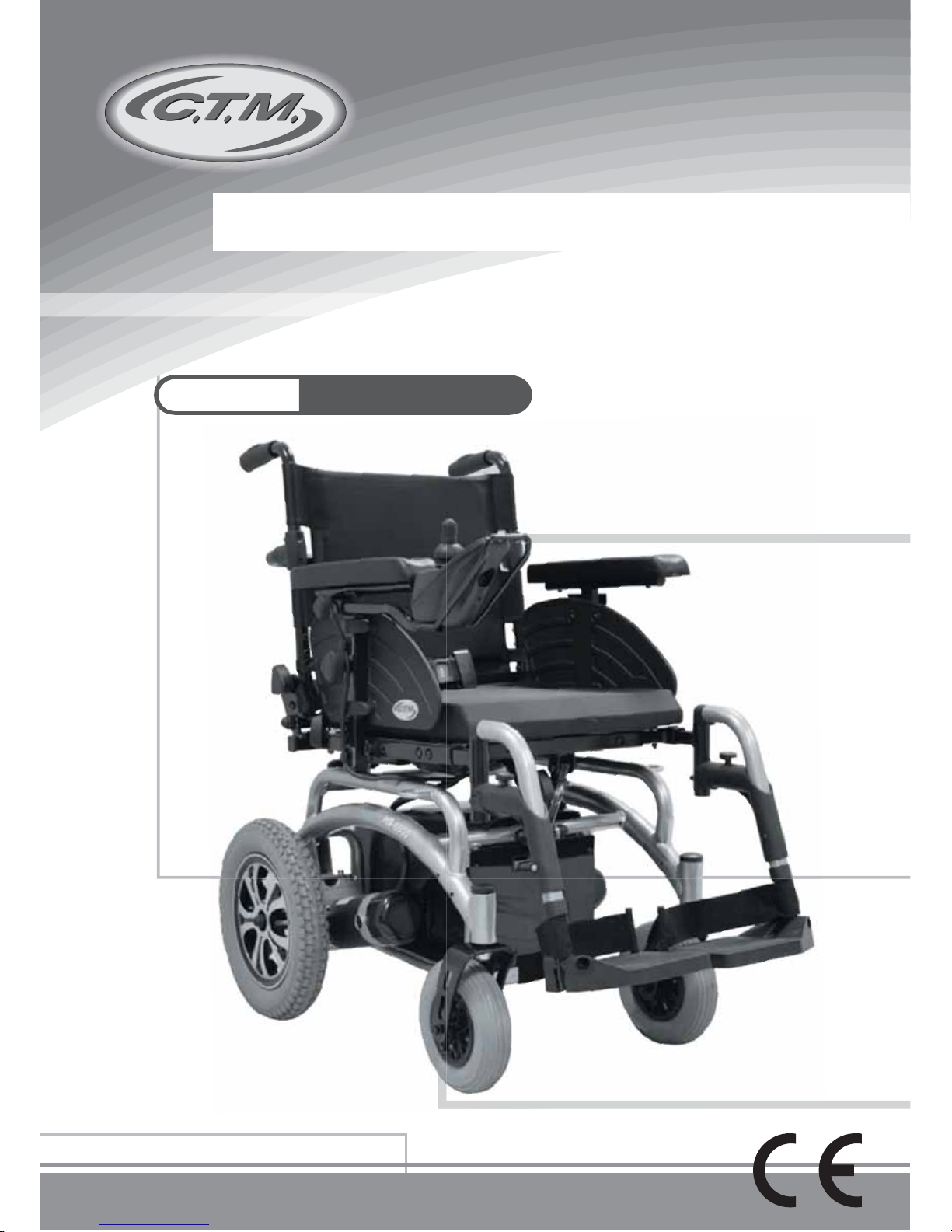
The HS-6500 is an excellent chair that includes ergonomic features. It combines safety
and comfort and gives users extraordinary experience and convenience in operation.
With its thoughtful and people-friendly controller system, the user can easily achieve
360 degree turns with their finger tips.
This product is powered by the sealed, no water added, high performance lead-acid battery,
which ensures environmental safety and brings convenience in disassembly and re-assembly.
This User's Manual contains important information and know-how on operating and
maintaining the C.T.M. product. Please read it carefully before practicing with your new
chair, so that you comprehend the technical advantages of HS-6500
All assembly and maintenance should be performed after you fully understand the content
of this manual to avoid any hazard or damage to the Power Chair or human body.
Overhaul and adjustments must be undertaken by skillful maintenance staff following the
instructions provided in this booklet.
Any improper usage might lead to danger to the user or the chair. C.T.M. is/will not be
responsible for any after-effect resulting from failure to comply with this manual.
1. When transporting HS-6500, please ensure the product is not scratched or damaged.
2. If a long trip is planned, please fully charge the batteries before use to prevent low
voltage during the trip.
All the contents in this manual including pictures, photo illustrations and text are all patented
and registered. (If any details in the manual are going to be changed or added, C.T.M.
will not notify previous owners of the modification.)
After unpacking, please inspect carefully for any defect or missing part.
Preface:
Limitation In Transporting And Travelling:

User's ManualHS-6500
Information of European Representative :
EMERGO EUROPE
Molenstraat 15
2513 BH, The Hague
The Netherlands
We wish you an enjoyable riding experience.
If you have any questions, you can contact:
CHIEN TI ENTERPRISE CO., LTD.
No.13, Lane 227, Fu Ying Rd., Hsin Chuang,Taipei, Taiwan,
Tel : +886-2-2903-2987 Fax : +886-2-2903-8807
E-Mail : sales@chienti.com.tw http : //www.chienti.com.tw
2

User's ManualHS-6500
ELECTROMAGNETIC INTERFERENCE
AND WARNINGS
3
CAUTION: It is very important that you read this information regarding the possible
effects of Electromagnetic Interference on your power chair.
Powered wheelchairs and motorized scooters may be susceptible to electromagnetic
interference (EMI), which is interfering electromagnetic energy (EM) emitted from sources
such as radio stations, TV stations, amateur radio (HAM) transmitters, two-way radios,
and cellular phones. The interference (from radio wave sources) can cause the power
chair to release its brakes, move by itself, or move in unintended directions. It can also
permanently damage the power chair control system. The intensity of the interfering
EM energy can be measured in volts per meter (V/m). Each power chair can resist EMI
up to a certain intensity.
This is called its "immunity level." The higher the immunity level,
the greater the protection will be. At this time, current technology is capable of achieving
at least a 20 V/m immunity level, which would provide useful protection from the more
common sources of radiated EMI.
The immunity level of this product is 20 V/m.
There are a number of sources of relatively intense electromagnetic fields in the everyday
environment. Some of these sources are obvious and easy to avoid. Others are not
apparent and exposure is unavoidable. However, we believe that by following the warnings
listed below, your risk to EMI will be minimized.
Some cellular telephones and similar devices transmit signals while
they are ON, even when not being used.
Electromagnetic Interference and Warnings:
The sources of radiated EMI can be broadly classified into three types:
1.Hand-held portable transceivers (transmitters-receivers) with the antenna mounted
directly on the transmitting unit. Examples include: citizens band (CB) radios,
"walkie talkie," security, fire, and police transceivers, cellular telephones, and other
personal communication devices.
2.Medium-range mobile transceivers, such as those used in police cars, fire trucks,
ambulances, and taxis. These usually have the antenna mounted on the outside of
the vehicle.
User's ManualHS-6500
4
3.Long-range transmitters and transceivers such as commercial broadcast transmitters
(radio and TV broadcast antenna towers) and amateur (HAM) radios.
Because EM energy rapidly becomes more intense as one moves closer to the transmitting
antenna (source), the EM fields from hand-held radio wave sources (transceivers) are of
special concern. It is possible to unintentionally bring high levels of EM energy very close
to the power chair control system while using these devices. This can affect power chair
movement and braking. Therefore, the warnings listed below are recommended to prevent
p
ossible interference with the control system of the power chair
.
Other types of hand-held devices, such as cordless phones, laptop
computers, AM/FM radios, TV sets, CD players, and cassette players,
and small appliances, such as electric shavers and hair dryers, so far
as we know, are not likely to cause EMI problems to your power chair
.
Power Chair Electromagnetic Interference:
Warnings
Electromagnetic interference (EMI) from sources such as radio and TV stations, amateur
radio (HAM) transmitters, two-way radios, and cellular phones can affect the power chair
.
Following the warnings listed below should reduce the chance of unintended brake release
or power chair movement, which could result in serious injury.
1.Do not operate hand-held transceivers (transmitters-receivers), such as citizens band
(CB) radios, or turn ON personal communication devices, such as cellular phones,
while the power chair is turned ON;
2.Be aware of nearby transmitters, such as radio or TV stations, and try to avoid coming
close to them;
3.If unintended movement or brake release occurs, turn the power chair OFF as soon
as it is safe;
4.Be aware that adding accessories or components, or modifying the power chair, may
make it more susceptible to EMI; and
5.Report all incidents of unintended movement or brake release to the distributor listed
on the inside front cover of this manual. Note whether there is a source of EMI nearby.
Electromagnetic Interference and Warnings:
Important Information
1.20 volts per meter V/m is a generally achievable and useful immunity level against EMI
(as of May 1994). The higher the level, the greater the protection.
2.The immunity level of this product is 20 V/m.

User's ManualHS-6500
SAFETY INSTRUCTIONS
Safety is the main consideration when practicing with your chair. It is required that you
read and comprehend all the operating and safety instructions discussed in this manual.
And ensure your chair is correctly fitted and adjusted by your dealer or the prescribing
healthcare professional.
Make sure to engage the wheel locks before entering or leaving the chair. The wheel locks
are designed to prevent movement of the chair. It is preferable to ensure the front castors
are in the forward position before transferring in to or out of the chair. With the castors
in the forward position the wheel base of the chair is increased and therefore, offers more
stability.
DO NOT move forward in the seat while leaning forward out of the chair. If an object is
to be picked up from the floor, drive past it, then reverse so the front castors are in the
forward position. This gives the chair its greatest stability.
To maintain lateral stability do not reach further than the length of your arm. DO NOT
lean out of the chair as this could cause instability.
When transferring, DO NOT stand on the leg rests. Depending on the style of leg rests
either swing them away or fold them up before transferring.
When approaching a ramp, be sure of your own ability and your limitations in terms of
strength and endurance.
Please be aware that any adjustments on the power chair may affect the
handling and performance.
5
Before attempting a ramp the following basic safety rules should be considered:
1. Surface of the ramp: Is it too slippery?
2. Degree of incline: Is it too steep to attempt alone?
3. Length of ramp: Is it too long for your endurance?
4. Obstacles: Are there any obstacles on the ramp that would necessitate assistance?
Be very careful when going up or down steep inclines
If it becomes necessary to stop when going up an incline, special care must be taken to
avoid abrupt or sudden forward movement. During continuous forward movements, the
chair is capable of falling backwards.
Always keep the chair under control when going down a ramp or incline. Speed should
be controlled at all times.
The user in the power chair and a curb is encountered, caution should be taken to
prevent the user being thrown forward:
Do not try to climb a curb by driving up it. Have a helper move the chair for you following
the instructions below.
1. With both motors disengaged, go down the curb, rear wheels first; making sure that
the user is square to the curb so that the rear wheels go down together.
2. To go up a curb forward, verify both front wheels are up together. This must be
accomplished with the motors disengaged.
Also try to avoid going up multiple steps and using escalators. Use the elevator instead.

User's ManualHS-6500
Figure 1 - HS-6500 Power Chair Front View
Figure 2 - HS-6500
Joystick Top View
Figure 3 - HS-6500 Power Chair Rear View
IDENTIFICATION OF PARTS
6
Before attempting to drive this power chair on your own, it is important that you familiarize
yourself with the controls and how they operate.
Controller Bracket
Adjustment Knob
Handlebar
Height Adjustable
Armrests
Armrest
Disassemble
Knob
Super Responsive Digital
Joystick Controller
Footrest Fixation Pin
Fiber Glass Reinforced
Nylon Leg Rests
Seat Incline Adjustment
Support Brace
Backrest Angle
Adjustment
Seat Width
Adjustment
Free Wheel
Lever
Anti-Tip Wheels
Seat Belt
Battery Level Indicator
Speed Indicator
Horn
On/Off Switch
Speed Control
Button

User's ManualHS-6500
Controller
OPERATION
7
1.By press On/Off Switch (A), Battery Level Indicator (B) will light up.
2.Battery Level Indicator (B) indicates power capacity.
3.Speed Control Button (C), (D):
•
Accelerate speed by pressing button (C)
•Decelerate speed by pressing button (D).
4. Horn (E):
Press it when necessary.
5.Directional movement is attained by controlling
the joystick (F)
•
Forwards : Move power chair forwards.
•Backwards : Move power chair backwards.
•Left : Move power chair left
•Right : Move power chair right
Controller Position Adjustment
By release Controller Bracket Adjustment Knob to adjust controller (G1) to a required
position.
Lighting System-Optional Accessory
1.Button (a): Activate lighting system.
2.Button (b): Activate warning light
3.Button (c): Right Turn Signal
4.Button (d): Left T
urn Signal
Figure 5
Figure 5
Figure 6
Figure 6
Figure 4
Figure 4
(B)
(A)
(C)
(D)
(G)
(c)
(e)
(a)
(b)
(d)
(G1)
(F)
(E)
To prevent any damages, be aware of the wire's length when adjusting.
Figure 7
Figure 7
 Loading...