

Service Manual
HS-268 / HS-268M
Product Qualified as CE for EU ●GMP for Taiwan (ROC) ●ISO9001, 13485 Certification
581201-26800

Table of Contents:
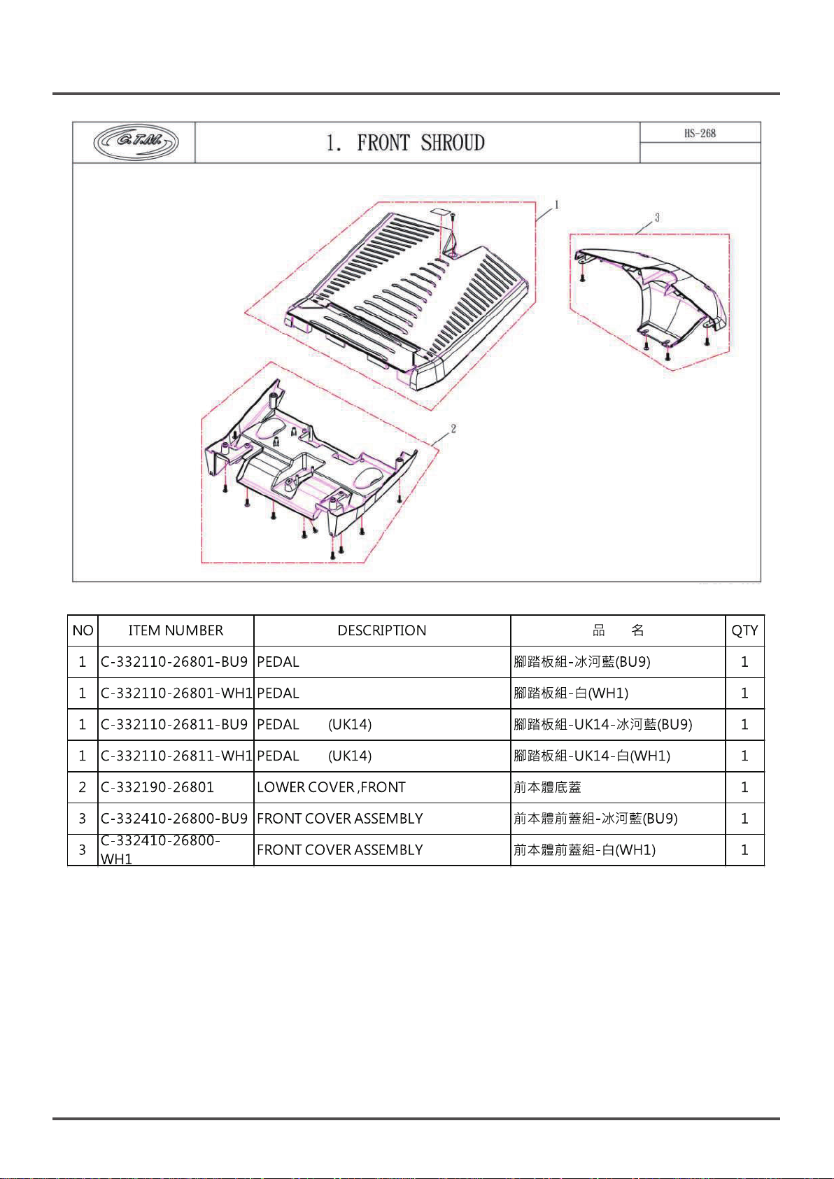
Front Cover - Shroud Component List
1
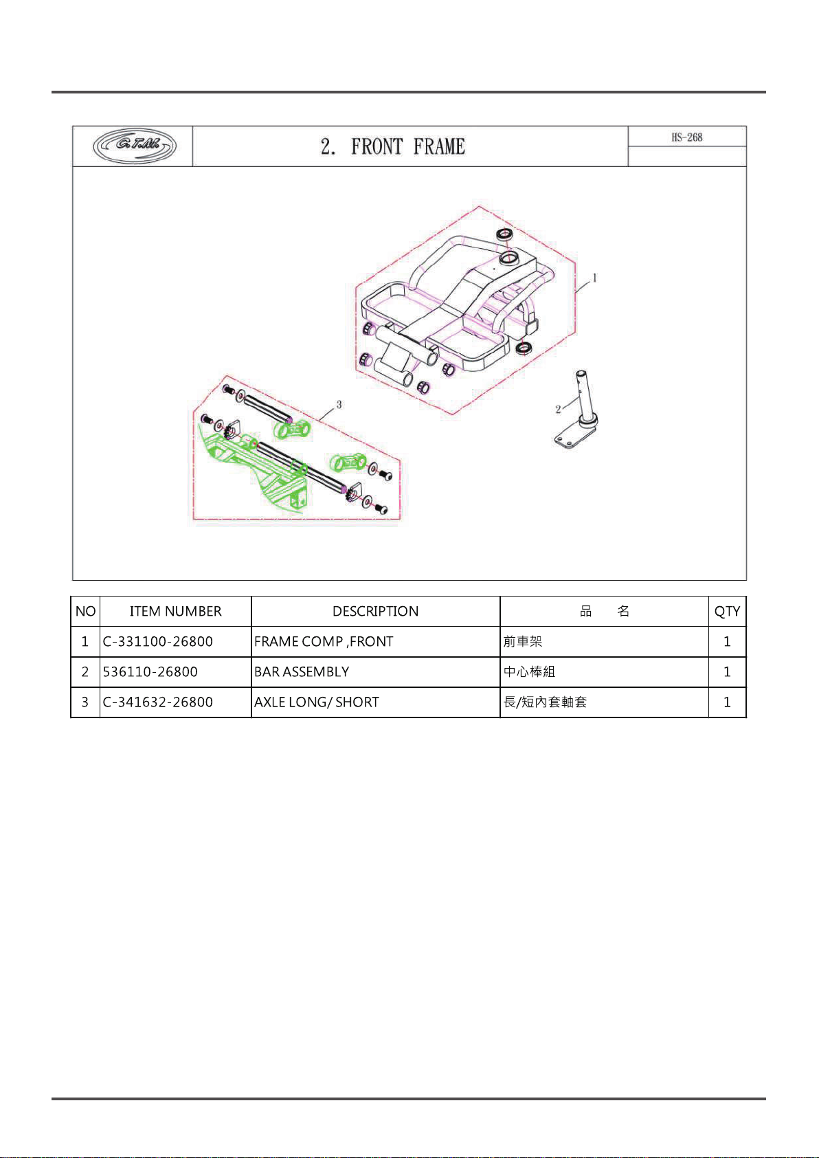
Front Cover - Frame Component List
2
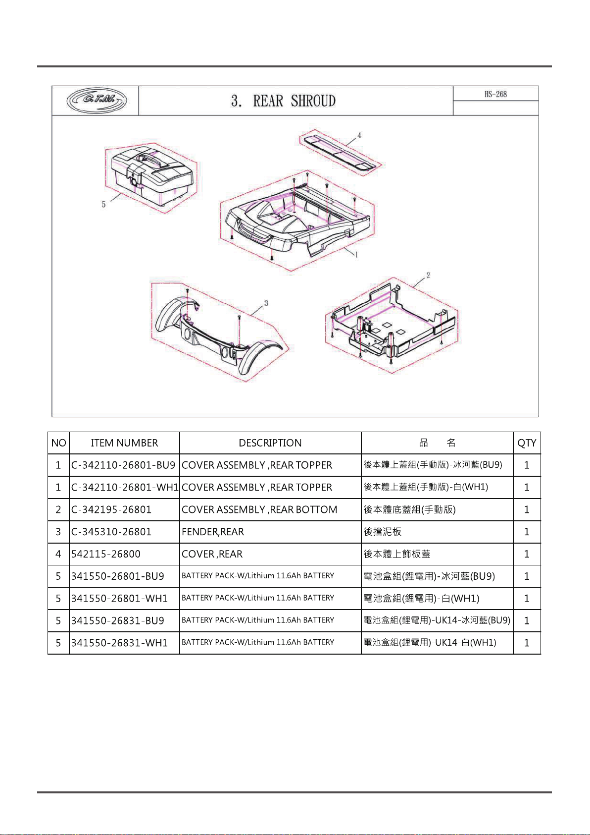
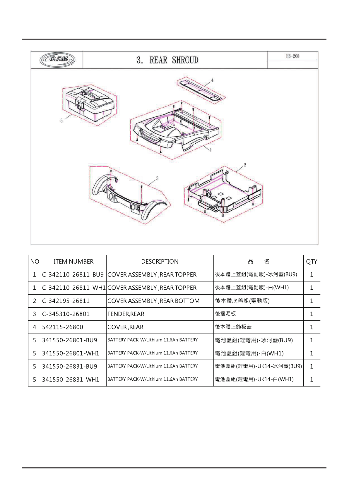
Rear Cover - Shroud Component List
3
•Manual Version
•Automatic Version
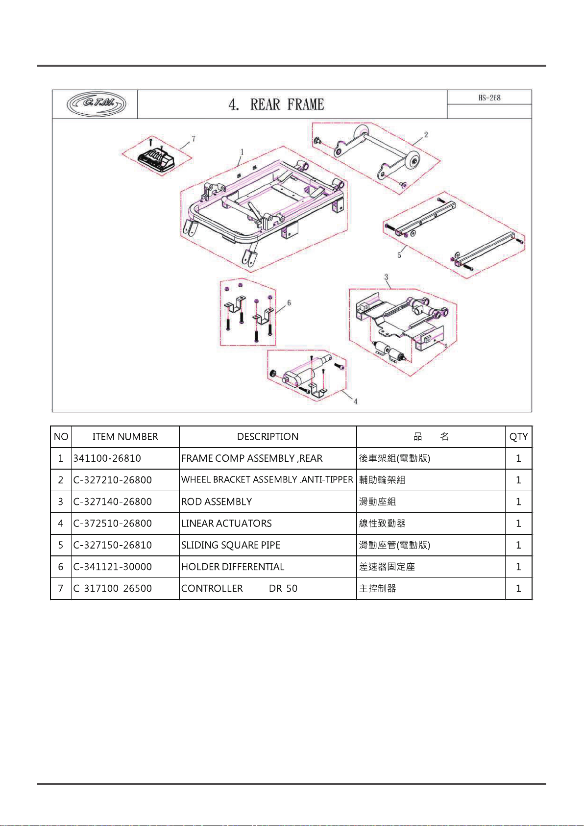
Rear Cover - Frame Component List
4
•Manual Version
•Automatic Version
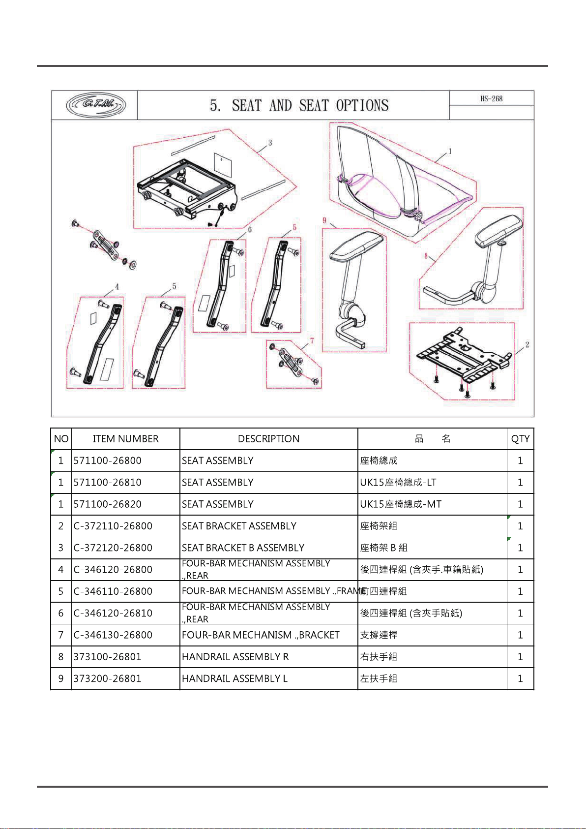
Seat and Seat Options Component List
5
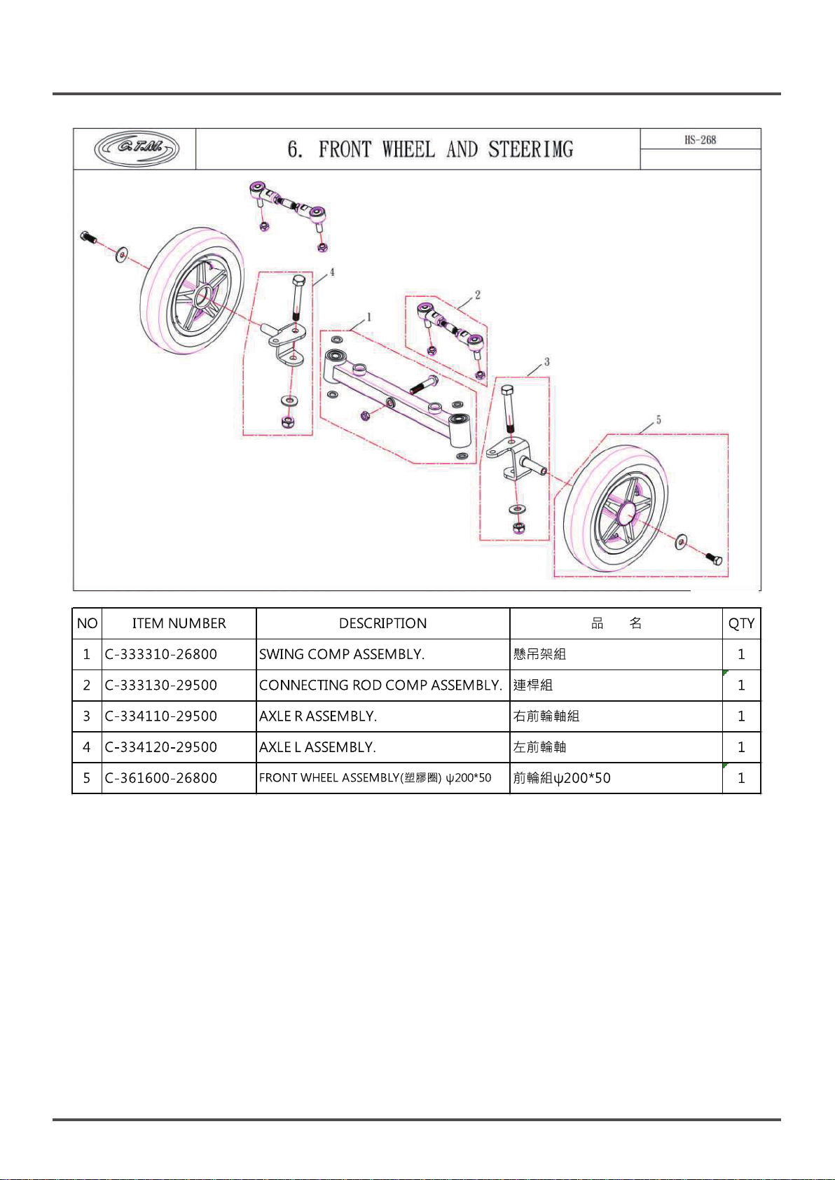
Front Wheel and Steering Component List
6
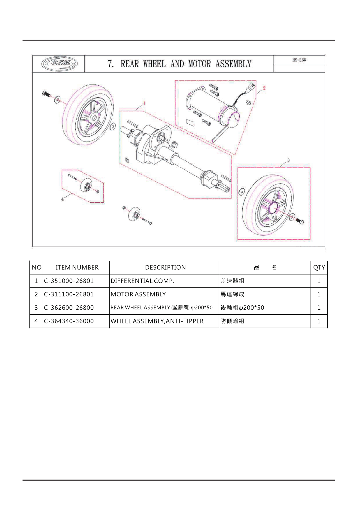
Rear Wheel and Motor Assembly Component List
7
..............................................1
...............................................3
...........................................9
4
6
8
9
.....................................11
..........................12
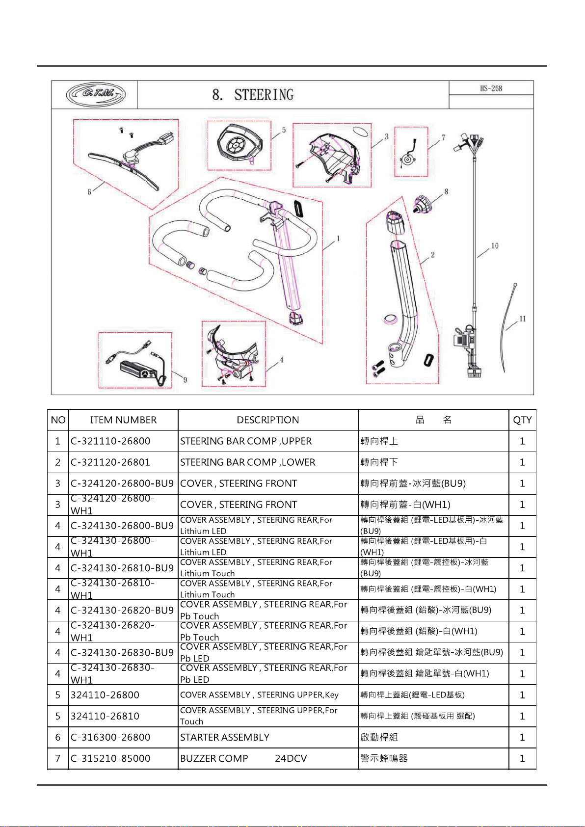
Steering Component List
8
•Manual Version
•Automatic Version
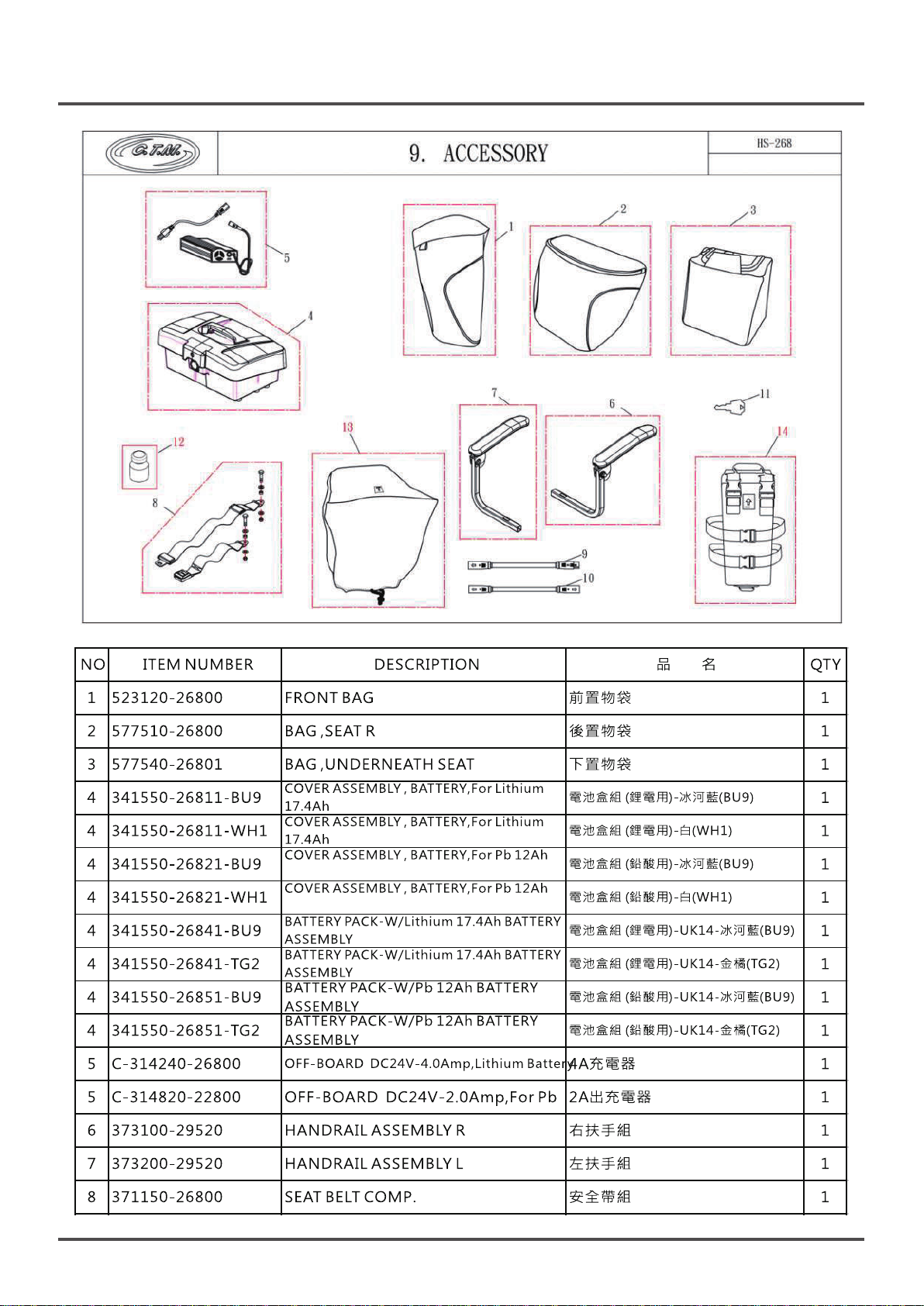
Accessory Component List
9
Repair Items
10
•Preparations for Repairs
•Basic Maintenance
•Service procedures
SERVICE - 01 - Steering Head Cover
SERVICE - 02 - Steering Bar
SERVICE - 03 - Front Lamp Cover
SERVICE - 04 - Front Wheel
SERVICE - 05 - Rear Wheel
SERVICE - 06 - Battery Pack
SERVICE - 07 - Seat
SERVICE - 08 - Seat Bar Mechanism
SERVICE - 09 - Front Lower Cover
SERVICE - 10 - Front Top Cover
SERVICE - 11 - Rear Top Cover
SERVICE - 12 - Rear Lower Cover
SERVICE - 13 - Frame
.....................................................................22
.............................................................17
13
15
16
21
23
30
32
33
34
35
41
42
44
46
48
53
59
123
Manual
Automatic
4

Manual
5
Automatic
6
789
Manual
10
11

Automatic
12

131415

Service manual
Preparations for Repairs :
•Please read this Service Manual carefully before attempting any repairs. Make sure you have identified
the cause of the failure before you start.
•Before starting to work on the scooter remove the battery to avoid electric shock or damage to
components of the electrical system.
•This Service manual has been prepared for the automatic version of the scooter. However, it can be used
when making repairs to the manual version. Some special repair procedures are marked as being “manual
version only”.
•Some repair procedures are relatively complicated and may need the operation of two persons.
•Please refer to the torque specifications when you use electric, pneumatic, or even manual tools to tighten
bolts, screws and nuts, to prevent damage to scooter parts.
•The drawings and diagrams in the manual may be slightly different from the appearance of the actual
scooter. However the repair procedures remain the same.
•After disassembl,make sure the parts are set aside carefully to avoid losing any of them.
•When old parts are replaced with new ones, the screws, washers, pads or auxiliary fixation parts are not
provided with the news parts. It may be necessary to use original parts when reassembling the scooter.
However, if any screw, washer or other part should appear to be worn, corroded, or damaged, it should
be replaced.
•When reassembling the scooter, please make sure to reassemble it in the proper order. Make sure all the
parts are secure and the scooter is in a good roadworthy condition to avoid accidents or injury to riders
or others.
•After the repair and reassembly has been completed, a test drive should be done to check that the fault
has been eliminated and that the scooter functions properly.
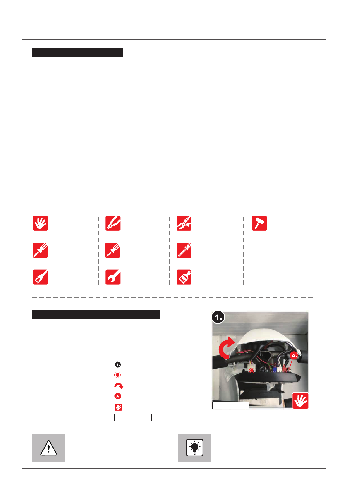
•The following is a list of tools necessary for this work: For details of tool specifications, please refer to
the instructions provided in the repair steps.
The Service manual
Flathead
screwdrivers
Socket tool set
Diagonal pliers
Cross screwdrivers
Adjustable wrench
Service manual Reading Instructions :
•Please follow all the steps in the order they appear
Step 1 → Step 2 as shown in the illustrations.
•Please refer to the pictures for instructions and details.
The pictures appear on the right and include detailed
descriptions of the procedures to be followed.
•Operation step code
•Key location indication
•Arrow direction indication
Lineman’s pliers Rubber hammer
Allen keys or drivers
Brush
•Detailed item code
•Tools needed
•Torque limits
•Indication for notes
Caution
If these instructions are not followed
carefully the result could be damage
to the scooter, or even personal injury.
18+-2kgf-cm
18+-2kgf-cm
(This drawing is for illustration only)
Recommendation
Frequent reference to the manual
during the repairs will facilitate the
operation.
16
Service manual
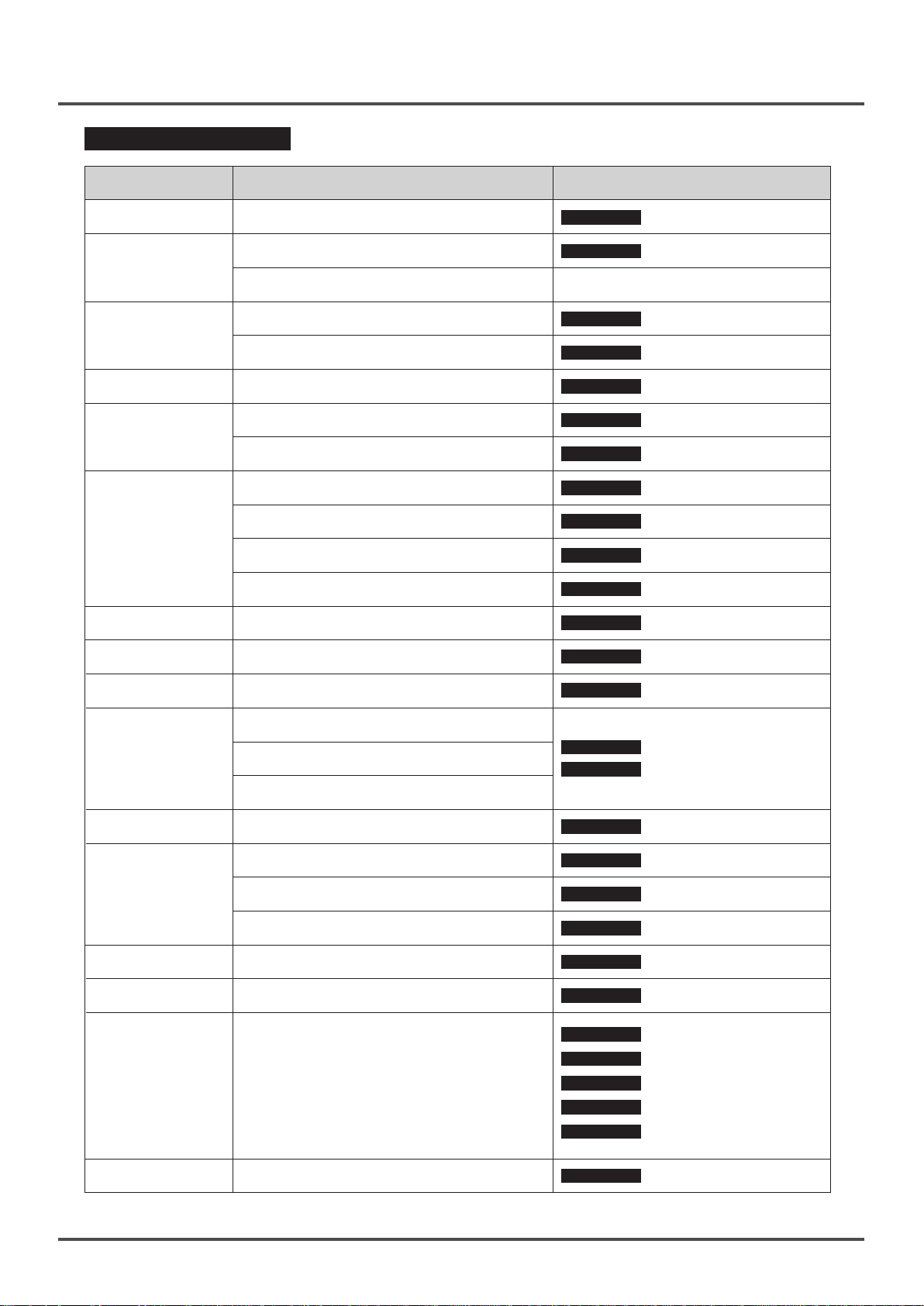
Description of Failure :
Parts involved Nature of Failure
Buzzer
Buzzer function fault
Panel light controls abnormal
Control Panel
Failure lamp comes on
Headlight failure
Headlight / T aillight
Taillight failure
N-D lever
Throttle
N-D lever abnormal, does not work,
or is jammed
Scooter forwards or backwards travel
abnormal
Electromagnetic brakes failure
Battery pack has been damaged
Battery pack does not charge
Battery pack
Battery pack power connection failure
Lithium battery ← Conversion → Lead-acid
battery
Remote controller
RF key
Speed regulator
button
Remote control faulty or lost
Sensor abnormal or lost
Speed regulator does not work
Chapter reference and Trouble -
shooting Method
SERVICE-1-2
SERVICE-1-1
Buzzer repair
Top control panel repair
Refer to "Self-Diagnostic Warning
Light" on the next page
SERVICE-3-1
SERVICE-11-2
SERVICE-13-5
SERVICE-1-3
SERVICE-11-1
SERVICE-6
SERVICE-6-1
SERVICE-6-2
SERVICE-6-3
SERVICE-12-2
SERVICE-1-5
SERVICE-1-1
Headlight repair
Taillight repair
Electromagnetic brake
repair
Starter VR repair
DR controller repair
Battery pack
Battery pack - Charger
socket repair
Battery pack - power
socket repair
Change the battery
Remote control board
repair
RF key setting
Upper control board repair
Tire
Motor
Seat
Steering bar
Rear fender
Shroud
frame
Crack/deformation/yellowing/or puncture
Wheel track depth less than 0.5mm
Tire wobbles or is unstable
Motor action abnormal or makes noisy sound
Seat damage repair or seat replacement
Seat has become loose
Seat spring action abnormal
Height adjustment problem
Rear fender damaged or makes an unusual
sound
Damage to the exterior plastic shroud
Frame has been deformed or broken
SERVICE-4
SERVICE-5
SERVICE-13-4
SERVICE-7
SERVICE-8-3
SERVICE-8-2
SERVICE-2
SERVICE-11-4
SERVICE-1
SERVICE-9
SERVICE-10
SERVICE-11
SERVICE-12
SERVICE-13
Front wheel repair.
Rear wheel repair
Motor repair
Seat repair
Seat locking pin repair
Seat spring repair
Steering bar repair
Rear fender repair
Repairs to Steering cover
Front lower cover
Front top cover
Rear top cover
Rear lower cover
Frame repair
17

Service manual
Folding / Unfolding Errors :
Code
1
2
3
4
5
6
7
8
Description What to do
Power On Turn off the main power switch
Battery Low Charge the battery immediately
Seat springs fall off
Seatback is not flipped down
Scooter is not on flat ground
Foreign Object on footplate.
Optional accessories
interference
Folding / unfolding light indicator
on scooter is not in orange
(enter into sleep mode)
Refer to SERVICE-7-1 Seat Spring
Repair
Flip down the seatback and restart the
folding / unfolding procedure.
Scooter cannot be folding / unfolding if
it’s not placed (lay down) on a flat ground.
Please place the scooter on a flat ground
and restart the folding / unfolding
procedure.
Check and remove the object on the
footplate and restart the folding /
unfolding procedure.
Remove obstructions such as :
handrails or baggage etc.
Acton :
1.Please wake up the
folding / unfolding function
(see figure on the right)
2. SERVICE-11-5 Folding / Unfolding
Board Repair.
9
10
11
12
13
Tapping error on the folding /
unfolding buttons
Scooter folds incorrectly
Scooter anti-tipping angle is too
great
Remote control inactive
Folding / unfolding button inactive.
If the “Folding button” is pressed when
the scooter has already been folded
it will fold further. Press “Unfolding
button” again and do this until the
scooter has been fully expanded.
Possible Solution :
1. SERVICE-13-1 Solenoid Valve Repair
SERVICE-13-2 Folding Unit Repair
(manual version only)
2. SERVICE-13-3 Sliding Track Repair
3. SERVICE-13-7 Linear Actuator Repair
4. SERVICE-13-8 gas spring Repair
5. SERVICE-13 Frame Repair
6. SERVICE-13-6 Sliding Base Repair
Scooter has anti-tipping protection,
please place it on flat ground and to
correct the problem.
Solution :
1.Battery needs to be replaced.
2.Refer to SERVICE-12-2 Remote
Board.
Refer to SERVICE-11-5 Folding /
Unfolding Board.
18
Service manual
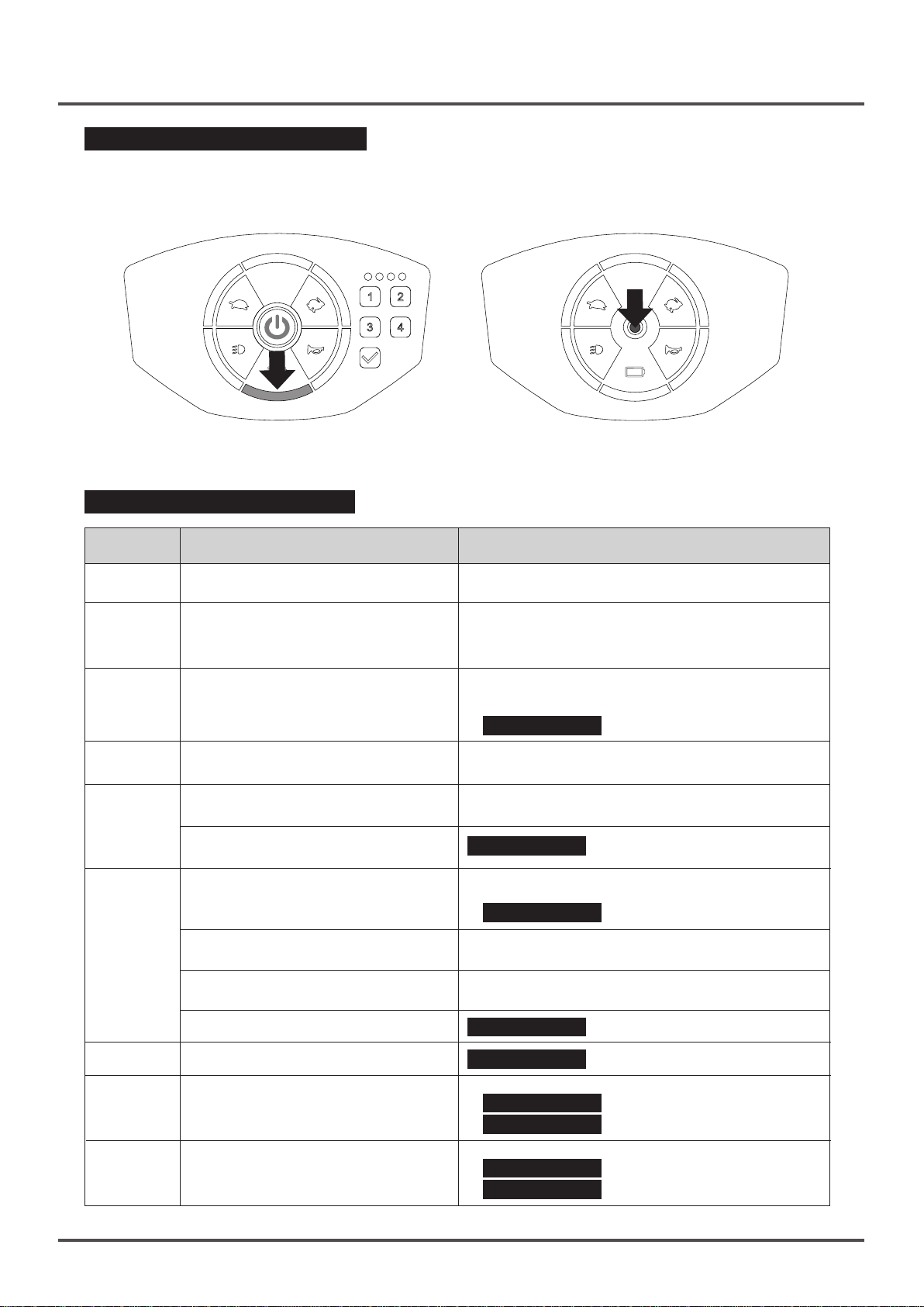
Self-Diagnostic Warning Light :
When the main power switch is turned on (4-2 Main power Switch Operation), The self-diagnostic warning
light will flash if there be any malfunction or failure.
Touch Version-self-diagnostic warning light, shared
with the battery indicator.
Manual Version-self-diagnostic warning light, shared
with the main power light.
Normal : remains on, as does the battery power
indicator.
Failure : flashes according to the nature of the
failure, see the table below.
Self-Diagnostic Warning Light
Number
of Flashes
1
2
3
4
Possible Cause Handling Method
Battery Low
Low Battery Fault
High Battery Fault
Current limit time-out or controller
overheat
N-D lever not set to D-position
5
Electromagnetic brake failure
The throttle is not in Neutral or the
folding / unfolding procedure is
uncompleted.
Normal : constant green light.
Failure : flashes according to the nature of failure,
refer to the table below.
The batteries are running low.
•Recharge the batteries.
The batteries have run out of charge.
•Recharge the batteries.
•Check the battery and associated connections
and wiring.
Handling method:
1.Disconnect the battery pack, and check
the battery condition.
2. SERVICE-6 Battery Pack Repair.
Do not drive up steep slopes or overload
the scooter.
Switch to D (drive) position. Turn off the power and
turn on again.
SERVICE-13-5 Electromagnetic Brake Repair.
Solution:
1. Repeat the folding or unfolding procedure.
2. SERVICE-1-3 Starter VR Repair.
6
7
8
9
The folding / unfolding procedure is
uncompleted
Scooter battery is being charged
Micro switch failure
Speed pot
Motor or relevant circuit failure
Main cable, controller failure or
controller temperature too high
Repeat the folding or unfolding procedure.
Turn off the main power and disconnect the
charger.
SERVICE-12-1 Micro Switch Repair.
SERVICE-1 Steering Cover Repair.
Solution:
1. SERVICE-11-1 DR Controller Repair
2. SERVICE-13-4 Motor Repair
Solution:
1. SERVICE-11-1 DR Controller Repair
2. SERVICE-2-1 Main Cable Repair
19

Service manual
Battery Indicator Instructions
After turning on the main power switch, the scooter battery indicator should be checked :
Silicon Button Panel - Battery Indicator
(Total 5 LED lights)
Number
of lights
LED - 5
lights
LED - 4
lights
LED - 3
lights
LED - 2
lights
LED - 1
lights
Number
of lights
LED - 6
lights
LED - 5
lights
Lead-acid
battery
≥ 24.6V
<24.6v
<24.1v
<23.7v
<23.4v
Lead-acid
battery
≥ 27.4v
<26.6v
Lithium
battery
≥ 27.4v
<27.4v
<24.1v
<23.7v
<23.4v
Lithium
battery
≥ 27.4v
<26.6V
Remarks
Battery power may be
insufficient for folding
or unfolding
Riding is not
recommended, and
battery should be
charged immediately
Remarks
Touch Panel-Battery Indicator
(Total 6 LED lights)
Battery circuit diagram
•Lithium battery - circuit diagram •Lead-acid battery - circuit diagram
LED - 4
lights
LED - 3
lights
LED - 2
lights
LED - 1
lights
<25.7v
<24.8v
<24.0
Constant lit up
<25.7v
<24.8v
<24.0v
Battery may be
insufficient for folding
/ unfolding
Riding is not
recommended, and
battery should be
charged immediately
Self-Diagnostic
Warning Light
20

Service manual
Basic Maintenance Instructions :
Periodic maintenance of the scooter can prolong its life. This is particularly important after a rainy day, or.
when humidity is high.
Maintenance Recommendation :
Seat : Clean with soap water and do not sit until the seat dries out.
Frame : Please use clean water and a wet cloth for cleaning.
Shroud : Use clean water and a wet cloth for wiping and cleaning. Wax can be used for protection after
it has been dried.
Caution : Spraying or washing the entire scooter may cause damage and must not be done.
Storage :
•Do not park the scooter in direct sunlight, or in the rain or snow. Avoid leaving it in a humid place for any
length of time.
•When it is necessary to park the scooter in a place where it can be subject to moisture or extreme weather,
take the battery out and keep it in a suitable dry place.
•When parking, ensure the seat is secured, the N-D lever set to D-position, and the power switch is “Off”.
•Before carrying out any maintenance, turn off the power, and make sure it is in D-position.
•If the scooter is to be parked for more than a week, make sure the battery is charged and disconnect it.
Make sure the battery connector in not in a place where it may cause a short circuit.
Lithium Battery Storage :
Storage Temperature : Less than 1 year : -20°C ~ 20°C
Less than 3 months : -20°C ~ 40°C
Less than 1 month : -20°C ~ 50°C
The highest temperature during battery transportation should be lower than 60°C
Lead-acid battery Storage : storage temperature -30oc ~ 50°C
Scooter Information Label :
Scooter information label is the identification of the scooter and is attached to the inner side of the seat bar.
The label has the following information:
Product Model Number Maximum Load Date of Manufacture
Serial Number Factory Address
Repair Items :
Please refer to the repair items
list on the next page.
21

Service manual
Repair Items :
1
SERVICE - 01 - Steering Cover Repair
....................................................23
S1-1 Top Control Panel Repair
S1-2 Buzzer Repair
S1-3 Starter VR Repair
S1-4 Metal Power Switch Repair
S1-5 RF Key Setting
S1-6 Steering Head Charger Socket Repair
2
SERVICE - 02 - Steering Bar Repair
........................................................30
S2-1 Main Cable Repair
3
SERVICE - 03 - Front Lamp Cover Repair
...............................................32
S3-1 Headlight Repair
4
SERVICE - 04 - Front Wheel Repair
5
SERVICE - 05 - Rear Wheel Repair
SERVICE - 06 - Battery Pack Repair
6
........................................................33
........................................................34
.......................................................35
S6-1 Battery Pack -Charger Socket Repair
S6-2 Battery Pack -Power Socket Repair
S6-3 Battery Removal and Repair
S6-4 Charger Repair
7
SERVICE - 07 - Seat Repair
....................................................................41
S7-1 Seat Spring Repair
8
SERVICE - 08 - Seat Bar Mechanism Repair
...........................................42
S8-1 Seat Base Repair
S8-2 Seat Base Spring Repair
S8-3 Seat Locking Pin Repair
9
SERVICE - 09 - Front Lower Cover Repair
10
SERVICE - 10 - Front Top Cover Repair
..............................................45
..................................................46
S10-1 Front Top Cover– Side Cover Repair
S10-2 Footplate Cover Repair
11
SERVICE - 11 - Rear Top Cover Repair
...................................................48
S11-1 DR Controller Repair
S11-2 Taillight Repair
S11-3 Power Socket Repair
S11-4 Rear Fender Repair
S11-5 Folding / Unfolding Board Repair
12
SERVICE - 12 - Rear Lower Cover Repair
...............................................53
S12-1 Micro Switch Repair
S12-2 Remote Control Board Repair
S12-3 Supporting Wheel Repair
13
SERVICE - 13 - Frame Repair
.................................................................58
S13-1 Solenoid Valve Repair
S13-2 Retractor Repair(manual version only)
S13-3 Sliding Track Repair
S13-4 Motor Repair
S13-5 Electromagnetic Brake Repair
S13-6 Butterfly Base Repair
S13-7 Linear Actuator Repair
S13-8 Gas Spring Repair (manual version only)
24
25
26
27
28
29
31
32
37
38
39
40
41
43
43
44
46
46
49
50
51
52
52
54
55
58
60
61
62
63
64
65
66
66
22

SERVICE - 1
Steering Cover Repair
1.Remove the steering head rear cover and panel screws (12mm, 2pcs)
2.Remove the three screws (12mm, 3pcs) on the steering head rear cover
3.Remove the starter rod screws (8mm, 2pcs)
4.Detach the steering head rear cover
5.Detach the panel and steering head top cover
6.Make sure all the connectors on the board are properly fastened
※When reassembling be sure to use the exact reverse sequence of operations.
Board Circuit Comparison Diagram :
Metal power switch connector
Power connector
Starter VR connector
Buzzer connector
Main cable connector (including headlight,
taillight, and folding / unfolding board)
23

SERVICE - 1 - 1
Top Control Panel Repair
1.Remove the steering head rear cover and panel screws (12mm/2pcs)
2.Open the steering head top cover
3.Also remove all of the connectors on the top control board (refer to the instructions on
the previous page for connectors)
4.Remove the four screws (8mm/2pcs) on the top control board
5.Remove the entire top control board and replace with a new one
※After replacing the parts be sure to use the exact reverse sequence of operations for
reassembly.
•The top control board connectors are color-coded to prevent mistakes
when reconnecting. However, It is recommended that a photo be taken
that shows the connector locations before removing the board to prevent
a hassle during re-installation.
•Step 2. If it cannot be removed, please refer to SERVICE-1 Steering
Cover Repair for complete details on disassembly.
•Please do not touch the terminals on the top control board, to prevent
damage to the control board circuitry.
•During replacement of the top control board, do not disturb the metal
power switch in the center.
•Make sure to match the connector colors and do not make modifications
to any cables or connections. Do not force connectors to avoid damage
to the electrics and the scooter.
24

SERVICE - 1 - 2
Buzzer Repair :
Refer to SERVICE-1
Steering Cover Repair steps as follows :
※Find the buzzer connector (figure on the right)
※Re-connect the buzzer connector (figure on the right)
※If it is not effective, go to “Buzzer Replacement” below.
Buzzer Replacement :
Please refer to SERVICE-1 Steering Cover Repair steps first, and then :
1.Remove the screws (16mm, 2pcs) on the handle and steering head front cover
2.Remove the steering head front cover and set it aside carefully
3.Remove the buzzer and handle screw (12mm, 1pc)
4.Take out the buzzer, and replace it with a new one.
※After the replacement of parts or re-installation, please follow the exact reverse sequence
for reassembly.
※If buzzer function is not restored, go to SERVICE-1-1 Top Control Panel Repair.
15kgf-cm
•Step 1.Use one hand to remove the screws and the other hand to hold
the steering head front cover to prevent it from falling.
•Step 4.Use one hand to remove the screws and one hand to hold the
buzzer to prevent it from falling.
25

SERVICE - 1 - 3
Starter VR Repair :
Please refer to SERVICE-1 Steering Cover Repair steps
as follows:
※Find the starter VR connector (figure on the right)
※Re-connect the starter VR (figure on the right)
※If function is not restored go to “Starter VR Replacement”
below.
Starter VR Replacement :
Refer to SERVICE-1 Steering Cover Repair steps as follows :
1.Remove the screws (16mm, 2pcs) on the handle and steering head front cover
2.Remove the steering head front cover and set it aside carefully
3.Remove the starter rod connector on the board
4.Remove the screws (12mm, 2pcs) of steering bar and starter VR
5.Take off the starter VR and connector
6.Take out the starter controller, and replace it with a new one
※After the replacement of parts or re-installation, please follow the exact reverse sequence
for reassembly
※If function has not been restored, go to SERVICE-1-1 Top Control Panel Repair.
15kgf-cm
26

SERVICE - 1 - 4
Metal Power Switch Repair :
Please refer to SERVICE-1 Steering Cover Repair steps as
follows:
※Find the metal power switch connector (figure on the right)
※Reconnect the metal power switch connector
※If it is not effective, go to “Metal Power Switch Replacement”
below.
Metal Power Switch Replacement :
Please refer to SERVICE-1 Steering Cover Repair steps as follows:
1.Use needle-nosed pliers to unfasten the nut
2.Remove the metal power switch nut
3.Take out the switch, and replace it with a new one
※After the replacement of parts or re-installation, please follow the exact reverse sequence
for reassembly.
※If switch function has not been restored, refer to SERVICE-1-1 Top Control Panel
Repair.
•The metal power switch can be fastened in place by hand. An overly tight
fastening can cause the touch panel to be dented inwards.
•Do not put any force on the metal power switch circuit to prevent any
damage that might affect its function.
27

SERVICE - 1 - 5
RF Key Setting :
Refer to SERVICE-1 Steering Cover Repair steps as follows :
1.Find the top control board setting button.
2.Press the metal switch once, and after turning on the power, the red metal switch light
should be on.
3.Press the setting button once, and the metal switch red light should flash.
4.After the flashing stops, place the RF key near the metal switch, the scooter can be
unlocked and setting has been completed.
※Replace the steering head top cover.
※If this has not been effective, refer to SERVICE-1-1 Top Control Panel Repair.
※The top control board of the scooter can memorize up to four sets of RF keys.
•After four RF keys have been memorized, setting a fifth will
cause the first to be erased.
•Setting for the old version RF key (figure on the right) is the same,
except in the new version the RF key is integrated with the remote
control.
28

SERVICE - 1 - 6
Steering Head Charger Socket Repair :
Refer to SERVICE-1 Steering Cover Repair steps as follows :
1.Find the steering head charger socket and connector.
2.Remove the steering head charger connector.
3.Use a cross-head screwdriver to remove the charger socket screws (8mm, 2PCS) on
the outside of the steering head.
4.Take out the complete steering head charger socket.
※After the replacement of parts or re-installation, please follow the exact reverse sequence
for reassembly.
※Lithium battery charger socket has 4 holes; the Lead-acid battery charger socket has
3 holes.
•After changing the battery type from lead-acid to lithium, or vice-versa,
make sure that the steering head charger socket SERVICE-6-1
and battery
pack charger sockets match the type of battery installed.
•Self-modification of charging cables or plugs and sockets is extremely
dangerous and can lead to short circuits and even fire.
29

SERVICE - 2
Steering Bar Repair
Remove covers as shown in SERVICE-3 Front Lamp Cover Repair, SERVICE-9 Front
Lower Cover Repair, SERVICE-10 Front Top Cover Repair, and SERVICE-11 Rear
Top Cover Repair.
Then proceed as follows below :
1.Remove the rear frame - left side hook (2 pcs) main cable.
2.Cut and remove the cable tie (2 pcs) of the front frame at the left side.
3.Cut and remove the cable tie (2 pcs) at the front end of the front frame.
4.Remove the two hexagon screws (#6/40mm, 2pcs) connected to the frame and the
steering bar.
5.Push the steering bar upwards for removal.
6.Take out the steering bar.
※After the replacement of parts or re-installation, please follow the exact reverse sequence
for reassembly.
250+-25kgf-cm
•Step 5. If it cannot be removed or replaced easily, use a rubber hammer
to drive bar into position.
•After cutting (steps 2 and 3), when re-installing, use a new cable tie and
place it in the original position.
30

SERVICE - 2 - 1
Main Cable Repair :
Follow the SERVICE-2 Steering Bar Repair steps and then
1.Please refer to SERVICE-1-2 Buzzer Repair / SERVICE-1-3 Starter VR Repair
to remove the buzzer and VR controller.
2.Insert the front end of the main cable into the hole on the top of the steering bar.
3.Remove the adjustment screw.
4.Disengage the central locking pin to separate the steering bar into upper and lower
sections.
5.Remove the main cable from the upper section of the steering bar.
6.Remove the main cable from the lower section of the steering bar.
7.Take out the main cable and the complete steering bar.
※After the replacement of parts or re-installation, please follow the exact reverse sequence
for reassembly.
31

SERVICE - 3
Front Lamp Cover Repair:
1.Remove the screws (12mm, 2pcs) on the outside of the front lamp cover
2.Remove the screws (12mm, 2pcs) from the inside of the headlight cover
3.Push the front lamp cover gently upward to separate it from the frame
※After the replacement of parts or re-installation, please follow the exact reverse sequence
for reassembly.
•If the scooter is folded it will be easier to carry out this operation.
SERVICE - 3 - 1
Headlight Repair :
Refer to SERVICE-1 Steering Top Cover Repair steps first,
and then :
※Find the headlight connector
※Reconnect the headlight connector
※If it is not effective, carry out the “Headlight Cover Connector
Inspection”.
Refer to SERVICE-3 Front Lamp Cover Repair steps, then :
※Find the front lamp cover connector (figure on the right).
※Reconnect the front lamp cover connector (figure on the
right).
※If it is not effective, go to SERVICE-3 Front Lamp Cover
Repair to replace it with a new one.
※If this does not solve the problem, refer to SERVICE-1-1
Top Cover Board Repair to replace this with a new one.
•The headlight is not a separate unit and cannot be replaced alone. It is
necessary to replace the entire front lamp cover.
32

SERVICE - 4
Front Wheel Repair :
1.Rotate the wheel to find the notch on the wheel cap
2.Insert a flat screwdriver into the notch and
3.Lift the wheel cap off to expose the hub
4.Remove the hexagonal headed bolt (#12) and washer in the center of the axle
5.Take the wheel off the axle.
※After the replacement of parts or re-installation, please follow the exact reverse sequence
for reassembly.
250+-25kgf-cm
•Before taking the wheel off, lift the scooter and place a support under the
axle to hold the scooter when the wheel has been taken off.
•When replacing the wheel make sure the sleeve is in the middle so the
wheel will go on properly.
33

SERVICE - 5
Rear Wheel Repair :
1.Rotate the wheel to find the notch on the wheel cap.
2.Insert a flat screwdriver into the notch and.
3.Lift the wheel cap off to expose the hub.
4.Remove the hexagonal headed bolt (#12) and washer in the center of the axle.
5.Take off the wheel, and remove the black washer at the back.
6.Turn the wheel around and remove the key in the center to complete the action.
※After the replacement of parts or re-installation, please follow the exact reverse sequence
for reassembly.
250+-25kgf-cm
•After Step 5 the black washer may be stick to the inside of the wheel hub
or on the axle. Make sure it does not get lost. Keep the washer and the
key safely aside for reuse because these parts are not provided with a new
tire or wheel assembly.
34

SERVICE - 6
Battery Pack Repair :
1.Remove the battery pack from the scooter
2.Turn it around and find the battery pack power socket
3.Use a multi-meter to measure the battery voltage. The black socket is negative the red
socket is positive.
4.Observe the reading on the multi-meter.
※Lithium battery measurement normal range : 19~29v
※Lithium battery measurement outside the normal range: below 19v, please refer to the
following “Battery Failure Instructions”.
※If the battery voltage is within the normal range, but it cannot be charged, the charger
may be faulty. Refer to SERVICE-6-4 Charger Inspection.
Battery Failure Instructions :
Confirm that the connectors are normal. If the lithium battery voltage is below 19v, please
charge the battery. After charging the battery for 30 minutes, measure again to check if
the voltage is still 19v :
1.If the voltage rises with charge, continue charging until the battery is fully charged.
2.If the voltage remains below 19v, the lithium battery has been damaged.
3.In this case refer to : SERVICE-6-3 Battery Pack Removal.
•The minimum voltage of a standard lead-acid battery is 19.2v.
35

Battery Pack Wiring Inspection :
1.Remove the battery pack from the scooter.
2.Turn the battery pack over and locate the six screws that hold the cover.
3.Remove the screws (12mm, 6pcs).
4.Remove the cover and open the battery pack.
5&6.Remove the battery main cable connector first, then check the rest of the connectors.
※After removing the battery main cable connector, please set it aside safely.
※For re-installation, please follow the exact reverse sequence.
※If a check shows the wiring to be normal, but the charger still does not charge the battery
pack, the charger may need to be replaced.
Lead-acid Battery Wiring Inspection :
1.Please follow the same steps as above to remove the
battery pack.
2.The connectors inside the pack can then be checked.
a.Negative power output charging wire - check the position
of the negative hole on the battery pack.
b&c.Series wiring set (without electrode wire).
d.Positive power output charging wire - check the position
of the positive electrode hole in the battery pack.
e.Charger socket power cable.
※Repair of the lead-acid battery is generally the same as
for the lithium battery. Except that SERVICE-6-3 Battery Pack-Battery Removal provides
special instructions for the removal and replacement of each kind of battery, for the
rest of the repair steps, refer to SERVICE-6-1 Battery Pack-Charger Socket
SERVICE-6-2 Battery Pack-Power Socket.
36

•During the replacement of the battery pack, please remove the battery
and prevent operation on the scooter directly to facilitate the replacement.
•When turning the battery pack over, do not drop it, or put it down hard on
the table. Place it down gently and avoid damage. Damage to a lithium
battery may cause a serious accident.
•Step 6. After removing the battery main cable connector, remember that
the battery end is still electrically connected, put it down carefully and
make sure there is no chance of a short circuit.
•Do not attempt to modify or repair the lithium battery inside the battery pack,
this can be very dangerous, and represents a severe hazard.
SERVICE - 6 - 1
Battery Pack-Charger Socket Repair :
Please refer to SERVICE-6 Battery Pack Repair steps and then :
※Find the charger socket connector inside the battery pack (Figure 1 below).
※Reconnect the battery pack charger socket connector.
※If this does not restore function, refer to the following “Replacement Instructions”.
Replacement Instructions :
After completing the SERVICE-6 Battery Pack Repair steps :
1.Remove the battery pack charger socket.
2.Remove the battery pack outer cover and the charger socket screws.
3.Remove the battery pack charger socket, and remove the inside metal sheet at the same time.
4.Take out the battery pack charger socket, and replace it with a new one.
※After the replacement of parts or re-installation, please follow the exact reverse sequence
for reassembly.
37

SERVICE - 6 - 2
Battery Pack-Power Socket Repair :
Please refer to SERVICE-6 Battery Pack Repair steps first, then :
※Find the battery pack charger connector (Figure 1 below).
※Reconnect the battery pack charger socket connector.
※If it is not effective, please refer to the following “Replacement Instructions”.
Replacement Instructions :
After completing the SERVICE-6 Battery Pack Repair steps :
1.Remove the battery pack charger socket.
2.Squeeze the two sides of the charger socket inside the battery pack and.
3.push it out of the battery pack gently.
4.Replace the battery pack power socket with a new one.
※After the replacement of parts or re-installation, please follow the exact reverse sequence
for reassembly.
Re-installation Instruction :
※When replacing the charger socket be sure it is the right
way around. Please refer to the pictures on the right. If
the connector position is incorrect, it will not be possible
to reinstall the battery pack.
38

SERVICE - 6 - 3
Battery Pack-Battery Removal
Please carry out the SERVICE-6 Battery Pack Repair steps then :
1.Turn the battery pack over gently and remove the screws to open the battery pack.
2.Take the lithium battery out.
3.The sticker on the lithium battery has a serial number and all the relevant information about
the pack, this including the battery specifications, warnings, date of manufacture, etc.
※For re-installation, reverse the sequence of these steps.
※To re-install a different type of battery (lithium battery/lead-acid battery), please refer
to the following battery setting instructions.
※A lead-acid battery is heavy and does not need to be secured with screws. Place it directly
into the pack and make the connections.
Lithium battery relevant specification.
Lithium battery warnings.
QR Code: Use such code to obtain
information related to the lithium battery.
15kgf-cm
Lithium battery serial number barcode.
Battery Setting Instructions :
Please refer to SERVICE-1 Steering Cover Repair steps then :
1.Find the small battery type selection switch on the lower part of the top control board.
2.Move it to LI (left): Lithium battery, or PB (right): Lead-acid battery.
3.This switch resets the parameters to suit the type of battery. Make sure to push the switch
completely to the end (either left or right). If this is not done properly, system determination
may fail.
※The Lead-acid / Lithium
battery parameter setting
can only be done on the
automatic version.
•After a change of battery type, be sure to change the steering head charger
socket SERVICE-1-6 and the battery pack charger socket SERVICE-6-1 .
Do not attempt to modify the charger socket or charger cable connector,
this can be very dangerous and have severe consequences.
•If the selection switch is not set for the correct type of battery after a change
of type, the scooter will run, but the battery level display on the panel will
not show the correct state of the battery.
•Do not attempt to modify the charger socket or charger cable connector,
this can be very dangerous and have severe consequences.
39

SERVICE - 1 - 1
1.Lithium Battery Standard 2A Charger (see figure on the right)
Output connector. Input range 100~240V
(The mains plug may vary depending on the sockets used in
the country or region.)
Input connector : four pin.
Description : The charging indicator shows Standby : red
light / Charging : orange light / Charged : green light.
2.Lead-acid battery charger (see figure on the right)
Output connector. Input range 100~240V (The mains plug
may vary depending on the sockets used in the country or
region.)
Input connector : four pin.
Description : The charging indicator shows : Standby - red
light; Charging : orange light; Charged : green light.
3.Lithium Battery Standard 4A Charger (see figure on the right)
Output connector. Input range 100~240V (The mains plug
may vary depending on the sockets used in the country or
region.)
Charger Repair
Input connector : four pin.
Description : The charging indicator shows : Standby - red
light ; Charging : orange light ; Charged : green light.
Charger Failure and Troubleshooting
※Power charger indicator (red light) not lit up :
Troubleshooting → If the voltage to the socket is normal and the charger does not work.
The charger needs to be replaced.
Charging indicator (orange light) not lit up :
Troubleshooting → Check if the charge output connector is properly connected to the battery
connector. If the connection is good, the battery may be faulty, refer to SERVICE-6-3
Battery Pack-Battery Removal, and replace the battery with a new one.
Charging indicator (orange light) changed to (green light) immediately :
Troubleshooting → Check if the battery is fully charged, if not, then the battery may be
faulty. Refer to SERVICE-6-3 Battery Pack - Battery Removal.
•The charger is a complicated device, and self - repair is not possible. In the
event that the charger fails to function it must be replaced with a new one.
•There are two types of charger, one for Lithium batteries and another for
Lead / Acid batteries and they are not interchangeable. These battery
chargers are incompatible and the modification of cables or connectors
in an attempt to convert a charger for use with another type of battery
would be extremely dangerous.
40

SERVICE - 7
Seat Repair
1.Use wrench (#12) and hex key to loosen the bolts and nuts holding the seat in place
at the back.
2.Remove the bolts, nuts and washers and set them carefully aside.
3.Compress the spring inwards with the fingers and pull it out of the hole in the seat slide
bracket.
4.Pull down and hold the seat springs to release the seat latch.
5.Push the seat bracket by thumbs towards the back of scooters to release the seat from
latch.
6.When the seat is released from latch, grab the seat and push it towards the back of
scooter to remove the seat.
※When replacing the seat, please follow the exact reverse sequence of these steps.
50+-5kgf-cm
SERVICE - 7 - 1
Seat Spring Repair
Please refer to SERVICE-7 Seat Repair steps first, then :
1.Remove the holding screws (6mm, 2pcs) at the front end of the seat base and.
2.take out the spring.
※Please follow the exact
reverse sequence of these
steps for reassembly.
41

SERVICE - 8
Seat Bar Mechanism Repair
Follow the steps in SERVICE-7 Seat Repair to remove the seat.
1.Locate the rear fender and locking pin of the seat bar mechanism.
2.Push the rear fender outwards carefully to separate it from the seat bar mechanism.
3.Use an Allen key or driver to remove the socket head screws (5mm #10, 2pcs) on each
side of the holding board.
4.Remove the socket head screws (25mm #10, 4pcs) on each side of the bar mechanism.
5.Take lift off the seat bar mechanism.
※For re-installation, please follow the exact reverse sequence of these steps.
※This operation could also be carried out without removing the seat base. However the
assembly is much more difficult to handle and is much heavier with the seat in place.
※For seat spring repair, please refer to SERVICE-7-1 Seat Spring Repair.
200+-20kgf-cm
•After the screws have been removed from the seat bar mechanism, it can
swing freely. Be careful not to get your fingers or a hand jammed under
the bar mechanism during this operation.
•If the seat base is to be removed, please refer to SERVICE-8-1 Seat Base
Repair.
200+-20kgf-cm
42

SERVICE - 8 - 1
Seat Base Repair
Please refer to SERVICE-7 Seat Repair to remove the seat first, then :
1.Uses pliers to open the bar spring notch.
2.Separate the bar spring from the seat base.
3&4.Remove the hex screws (25mm #10, 4pcs) on both sides of the seat base and bar.
5.Take out the seat base.
※When reassembling, please follow the exact reverse sequence of these steps.
200+-20kgf-cm
•Step 1.When opening the bar spring, be careful not to use too much force
which might damage the spring.
•Step 2.For re-installation, please hook the spring onto the locking plate of
the seat base from below. If it is to be removed, please refer to.
SERVICE - 8 - 2
Seat Base Spring Repair
first and follow Step 2 of SERVICE-8-1 Seat Base Repair, then :
1.Remove the seat bar screws (6mm, 2pcs).
2.Take out the seat base spring.
※When reassembling,
follow the exact reverse
sequence of these steps.
43

SERVICE - 8 - 3
Seat Locking Pin Repair
Please refer to SERVICE-8-1 Seat Base Repair to remove the seat base, then :
1.Loosen the quick-release screw.
2.Take the quick-release screw out.
3.Remove the top washer.
4.Remove the seat locking pin and spring from the other side of the seat base.
5.Take out the seat spring.
※When reassembling, follow the exact reverse sequence of these steps.
Note for re-installation :
When re-installing, apply a little silicon oil to the pin, see the rectangular area shown in
the picture on the right.
44

SERVICE - 9
Front Lower Cover Repair
1.There are 9 holding screws at the bottom of the scooter front lower cover.
2.Remove the cover screws (12mm, 9pcs) and set them carefully aside.
3.Take off the cover.
※When reassembling, please follow the exact reverse sequence of these steps.
•Before removing the cover, elevate the front of the scooter on blocks, or
fold it, so that the front wheels are off the ground. This makes inspection
and replacement much easier.
•When removing the screws, start with those on the sides, and when replacing
them start with those in the middle. This makes it easier to set the cover
outer locking pins in place.
45

SERVICE - 10
Front Top Cover Repair
Please follow the SERVICE-3 Front Lamp Cover Repair and SERVICE-9 Front Lower
Cover Repair steps first, then :
1.Remove the front lamp cover and front lower cover.
2.Remove the central screw (16mm, 1pc) at the center of the front end of the top cover.
3.Take off the cover.
※When reassembling, please follow the exact reverse sequence of these steps.
SERVICE - 10 - 1
Front Top Cover-Side Cover Repair
Please follow SERVICE-10 Front Top Cover Repair to remove the cover, then :
1.Find the three locking pins at the sides of the front lower cover - left and right side cover.
2.Push the pins outwards.
3.Take the side cover off both sides.
※When reassembling, please follow the exact reverse sequence of these steps.
SERVICE - 10 - 2
Footplate Cover Replacement
Please refer to SERVICE-10 Front Top Cover Repair to remove the cover, then :
1.Press the front top cover downwards by hand.
2.Allow the cover to disengage from the center locking pin.
3.Gently bend the cover downwards to disengage from the right side locking pin.
4.Remove the locking pin spring on the left side.
5.Take the footplate cover off.
※When reassembling, please follow the exact reverse sequence of these steps.
46

•After removing the footplate spring, keep it aside carefully. The re-installation
of the spring is more complicated. Refer to the following figures for instructions
for its replacement
•Step 5.When replacing the footplate spring, do not use too much force.
This might deform it and cause a loss of function.
•Please do not leave the footplate cover off, it must be replaced. Leaving
it off is dangerous for the user and may also damage the scooter.
Spring Re-installation Instructions
※Spring location (Figure a. on the right) : Long end to the left / short end to the right.
※Re-install at the locking pin on the left side of the footplate cover.
※Spring mounted into the locking pin at the left side.
※For the rest of the re-installation refer to Step 3 → Step 1 of SERVICE-10-2 Front T op
Cover Repair.
The footplate cover should be lifted occasionally (without removal) so that the gears shown
in Figure b. to the right, can be lubricated. This is important and should be done regularly
to prolong the useful life of
the scooter.
47

SERVICE - 11
Rear Top Cover Repair
1.Remove the two inner screws (12mm, 2pcs) underneath the rear top cover.
2.Remove the rear footplate cover, by disengaging the three locking pins and pulling it
upwards.
3.Take out the rear footplate cover.
4.Remove the four screws (12mm, 4pcs) at the rear of the top cover.
5.Raise the top cover carefully.
6.Remove the three connectors on the inside of the cover.
7.Take the cover off.
※When reassembling, please follow the exact reverse sequence of these steps.
※For instructions about the connectors, refer to the content of the next page.
•Step 5.Lift the top cover carefully. Do not use force because this could
damage the three circuit connectors. These should be disconnected
carefully.
48

SERVICE - 11 - 1
DR Controller Repair
Picture showing rear top cover circuit connectors.
Rear top cover - folding board control connector
Rear top cover - taillight connector
Rear top cover - battery power connector
Remote control board - folding suppression connector
Main cable connector
Micro switch connector
Electromagnetic brake connector
Motor power connector
Linear actuator - power connector
Remote control board - power connector
※If the connections are good (the wires are undamaged and not loose), but the action
still fails, refer to the following DR Controller Replacement.
•The connectors underneath the rear top cover can be checked without
removing the cover. Refer to Step 5 of SERVICE-11 Rear Top Cover
Repair, to ensure the connections are made (for connector instructions,
please refer to the above connector codes).
DR Controller Replacement :
Please refer to SERVICE-11 Rear Top Cover Repair for removal, then perform :
1.Unplug all the connectors on the controller.
2.Remove the two screws on the DR controller to separate it from the frame.
3.Take the DR controller out.
※When reassembling, please follow the exact reverse sequence of these steps.
※After re-installation check to make sure all the connections are correct and secure.
15+-2kgf-cm
49

SERVICE - 11 - 2
Taillight Repair :
Follow the SERVICE-1 Steering Top Cover Repair steps and
then :
※Find the main cable connector (see picture on the right).
※Check the connector for security and reconnect if necessary
(picture of the right).
※If this does not restore function, refer to the following method.
Please follow the SERVICE-11 Rear Top Cover Repair steps
for removal, then :
※Find the taillight connector (figure on the right)
※Check the connector for security and reconnect (figure on
the right)
※If this is not effective, go to the following “Replacement
Instructions”.
Replacement Instructions :
Please follow the SERVICE-11 Rear Top Cover steps for removal, then :
1.Locate the taillight at the rear of the scooter.
2.Remove the two screws holding the rear cover.
3.Take out the taillight and replace it with a new one.
※When reassembling, please follow the exact reverse sequence of these steps.
※If this does not restore function, refer to.
SERVICE-1-1 Top Control Panel Repair, or
SERVICE-11-1 DR Controller Repair to replace a faulty board.
50

SERVICE - 11 - 3
Power Socket Repair
Please follow the SERVICE-11 Rear Top Cover Repair steps,
then :
※Find the rear top cover - power socket connector (picture
on the right).
※Check the connector for security and reconnect (picture
on the right).
※If this is not effective, please refer to the following “Replacement
Instructions”.
Replacement Instructions :
Complete the SERVICE-11 Rear Top Cover Repair to remove
the cover, then :
1.Unplug the rear top cover - power socket connector.
2.Squeeze the two sides of the power socket inside the battery pack and.
3.Push the socket out from the inside.
4.Take the power socket out.
※When reassembling, please follow the exact reverse sequence of these steps.
※During replacement or re-installation, please be aware of the connector position, refer
to the figure on the lower right and the instructions below.
※If function is not restored, refer to.
SERVICE-1-1 Top Control Board Repair, or
SERVICE-11-1 DR Controller Repair to replace a faulty board with a new one.
Re-installation Instructions :
※When re-installing the charger socket, make
sure it is the right position, see the picture on
the right. If the connector position is incorrect,
it will not be possible to reinstall the battery
pack.
51

SERVICE - 11 - 4
Rear Fender Repair
Please follow the SERVICE-11 Rear Top Cover Repair steps for removal, then :
1.Disengage the locking pins on both sides of the rear fender and seat bar mechanism.
2&3.Remove the screws (12mm, 4pcs) on both sides of the rear fender.
4.Pull the rear fender back to separate it from the frame.
5Take the rear fender off.
※For re-installation, follow the exact reverse sequence of these steps.
•Step 4.When the N-D lever is in the D- position, the rear fender may not
be easy to remove. Shift the gear to the N position to make removal easier.
SERVICE - 11 - 5
Folding / Unfolding Board Repair
Complete the steps of SERVICE-11 Rear Top Cover Repair to remove the cover, then :
1.Find the folding / unfolding board inside the Scooter.
2.Remove the two screws holding the board.
3.Take the board out.
※For re-installation, follow the exact reverse sequence of these steps.
52

SERVICE - 12
Rear Lower Cover Repair
Please follow the SERVICE-11 Rear Top Cover Repair steps for removal, then :
1.Remove the rear top cover, and find the cable ties on both sides.
2.Cut and remove the cable ties on the wires on both sides.
3&4.Unplug all the connectors on the rear lower cover and DR controller.
5.Locate the four screws (12mm, 4pcs) holding the bottom of the rear lower cover.
6.Remove the four screws.
7.Open up the rear lower cover, and tear off the solenoid valve tape on both sides.
8.Disengage the solenoid valve connectors on both sides, and disconnect the lower cover hook.
9.Take the cover off.
※When reinstalling, please carry out these steps in the exact reverse sequence. Please
also refer to the Cautions on the next page.
※For relevant connectors, please refer to the instructions on the next page.
•Re-installation of the lower cover is more complicated because incorrect
connections will cause malfunction. Please refer to the re-installation
instructions on the next page.
•Steps 3 and 4.For connector positions and instructions, please refer to the
instructions in SERVICE-11 Rear Top Cover Repair.
53

Connector Instructions :
Solenoid valve connector-left.
Solenoid valve connector-right.
For other connectors, please refer to the instructions in
SERVICE-11 Rear Top Cover Repair For solenoid valve
repair, please refer to SERVICE-12-3 .
Re-installation Instructions :
1.Connector wiring needs to be passed through the rectangular areas marked in the figure,
and the wires must be sorted according to the connector codes shown in the picture.
2.When re-installing a solenoid valve connector, make sure the locking pin is facing up
and attach the tape or sticker to prevent interference during folding. For other connectors,
please refer to the instructions in SERVICE-11 Rear Top Cover Repair.
When sorting out the wires make sure that the solenoid valve connector is
not attached or secured to the rear lower cover hook, it may interfere with
folding of the scooter, or even rip and damage the solenoid valve connector.
Pay special attention to this stage of the operation.
SERVICE - 12 - 1
Micro Switch Repair
Please carry out the SERVICE-12 Rear Lower Cover Repair steps first, then :
1.Find the micro switch which is located on the inside of the rear lower cover.
2.Remove the two screws (8mm, 2pcs) on the cover.
3.Take micro switch out.
※When reinstalling, please carry out these steps in the exact reverse sequence.
54

SERVICE - 12 - 2
Remote Control Board Repair
Remote Control Board Repair :
Please carry out the SERVICE-12-1 Micro Switch Repair steps for removal, then :
1.Locate the waterproof cover of the remote control board inside the rear lower cover.
2.Remove the four screws on the cover.
3.Take the cover off to expose the remote control board.
※When reinstalling, please carry out these steps in the exact reverse sequence.
※For relevant operations of the remote control board, please refer to the following
“Remote Controller Setting”.
Remote Control External Frequency Pairing Setting :
Unfold the scooter and equip with battery pack.
1.Turn on the main power switch, and unlock the scooter.
2.Long-press the folding and unfolding buttons at the same time for 2 seconds. The
board indicator (orange light) comes on to indicate it is ready for setup.
3.Press either the folding or unfolding button once of the remote control and the light
indicator will flash. When the indicator stops flashing, setting is complete. A maximum
of four remote controls can be set up on the same unit of scooter.
4.Turn off the main power switch.
5.Press the folding / unfolding button to check if the setting has been successful. Repeat
the setting if the scooter does not fold.
※Step 2.In the setting state, a long press of 5 seconds, on either the folding or unfolding
button, will erase all remote control settings. After an erase the board indicator light will turn off.
※If this does not work, go to “Remote Controller Internal Setting” on next page.
55

Remote Controller Internal Frequency Pairing Setting :
Refer to the SERVICE-12-2 Remote Control Board Repair steps, then :
1.Remove the waterproof cover and set it aside.
2.Check all the connectors on the rear lower cover with the DR controller (only connectors
without locking).
※Refer to the connector instructions in SERVICE-12 Rear Lower Cover for details.
3.Turn on the power to the remote control board, and press the setting button (long-press
for 3 seconds).
4.The remote control board blue light will come on and the remote control is ready for
pairing.
5.Press the “unfolding button”. When the indicator stops flashing, setting is complete.
※When reinstalling, carry out these steps in the exact reverse sequence.
※If function has not been restored, refer to “Remote Control Board Replacement” on the
next page.
•The remote control board can be set for a maximum of four
remote controls at the same time. When it is necessary to set
more, erase the settings on the remote control (instructions
are on the previous page) and start the setting again.
•Older versions of the remote controller (see picture on the right)
can only be used for “remote control internal setting”, they will
not work with “remote control external setting”.
56

Remote Control Board Replacement
Refer to the SERVICE-12-2 Remote Control Board Repair steps, then :
1.Detach the battery connectors from the hooks on the rear lower cover.
2.Remove the connectors from the remote control board.
3.Remove the remote control board main cable.
4.Remove the four screws (8mm, 4pcs) holding the remote control board in place.
5.Take the remote control board out.
※When reinstalling, carry out these steps in the exact reverse sequence.
※If function is not restored refer to SERVICE-11-1 DR Controller Repair to replace it
with a new one.
•Set the four screws and the remote control board main cable aside carefully
because these parts are not included with a new board.
•When making the installation be careful not to damage the terminal on the
control board.
•After the remote control board has been replaced, the RF remote controller
that came with the scooter will need to be set up again.
57

SERVICE - 12 - 3
Supporting Wheel Repair
Refer to SERVICE-9 Front Lower Cover Repair SERVICE-10 Front Top Cover Repair
SERVICE-11 Rear Top Cover Repair SERVICE-12 Rear Lower Cover Repair, and after
removing the above items, then :
1.Secure the two fastening points on the supporting heel and the rear frame.
2&3.Use an Allen key or wrench (#10) to remove the holding screws (14mm, 2pcs) on
both sides.
4.Disengage from the gear on the front frame.
5.Take the supporting wheel off.
※When reinstalling, make sure to carry out these steps in the exact reverse sequence.
200+-20kgf-cm 200+-20kgf-cm
SERVICE - 13
Please refer to SERVICE-9 Front Lower Cover Repair SERVICE-10 Front Top Cover
Repair SERVICE-4 Front Wheel Repair SERVICE-11 Rear Lower Cover Repair
SERVICE-12 Rear Top Cover Repair SERVICE-5 Rear Wheel Repair SERVICE-2
Steering Bar Repair SERVICE-11-1 DR Controller Repair, and after removing the above
items, then :
1.Use an Allen key or driver (#6) to unfasten the screw on one side (underneath the front
and rear frames) and then remove the screws (20mm, 2pcs) and washers on the other side.
2.After removing the screws at one end, use a rubber hammer and metal tool to knock
out the small metal rod.
3.Use an Allen key or driver (#6) to unfasten a screw on one side the top of the front and
rear frames; then remove the screws (20mm, 2pcs), washers and gears on the other side.
4.Then, as is step 2, use a rubber hammer and metal tool to knock out the large metal rod.
5.Take off the front frame.
6.Take off the rear frame.
※When reinstalling, please carry out these steps in the exact reverse sequence, and refer
to the following re-installation instructions.
Frame Repair :
58

150+-15kgf-cm 150+-15kgf-cm
Re-installation Instructions :
※During re-installation of the screws and washers, please be careful about the placement
of the gears on each side. The flat side of the gear must be flush with the front frame
and the white dot must face upwards. An incorrect installation can result in a failure
and will damage the scooter. See Figure 1 on the right for the correct arrangement.
※When re-installing the small and large metal rods apply some silicon oil to make installation
easier (see Figure 2 on the right).
•Step 5.Front frame can be replaced with a new one and can also be repaired.
•Step 6.If the rear frame is not separated completely, and it needs to be.
replaced, please refer to SERVICE-13-6 Sliding Base Repair.
59

SERVICE - 13 - 1
Solenoid Valve Repair :
Please refer to SERVICE-12 Rear Lower Cover Repair steps
first, then :
※Find the left and right -solenoid valve wiring inside the lower cover.
※Check the connections and re-connect the wires if necessary.
※If this does not restore function refer to the following “Solenoid
Valve Replacement”.
Solenoid Valve Replacement :
Please remove the connectors.
1&2.Use an open wrench (#21) to loosen the valves.
3.Take them out.
※When replacing the valves follow the “Re-installation Instructions” below and carry out
the “Re-installation Test”.
70+-7kgf-cm 0+-7kgf-cm
Re-installation Instructions :
※Before re-installation, apply a little gel to the threads on the valve
to ensure they do not come loose, see the picture on the right.
※Be careful not to get any gel on the plunger because this will
cause a malfunction.
※During re-installation be careful to ensure the threaded portion
goes in straight and the solenoid is tightened properly in place.
Re-installation Test :
※Turn on the power and allow the scooter to perform a folding → deployment action.
1.Make a mark 19mm from the end of a short rod, see the picture on the right.
2.Remove the circular stickers on each side of the scooter frame, see picture.
3.Insert the probe into the hole on each side of the frame.
4.If the rod does not go past the 19mm mark the installation has been successful.
※Replace the stickers to prevent water getting into the holes.
60

SERVICE - 13 - 2
Folding Unit Repair (manual only)
Carry out all the SERVICE-11 Rear Top Cover Repair SERVICE-12 Rear Lower Cover
Repair SERVICE-11-5 Rear Fender Repair steps, and when this has been done, then :
1.Locate the folding unit locking pins on each side of the bottom of the scooter frame.
2.Use a wrench (#17) to remove the locking pins.
3.Cut and remove the cable tie (x1pc) on the frame and remove the steel cable.
4.Use a cross-head screwdriver to remove the screws (12mm, 2pcs) from the plastic shroud.
5.Use a cross-head screwdriver to remove the screws (20mm, 2pcs) that hold the folding unit.
6.Take out the entire folding unit set.
※When replacing parts or re-installing, carry out these steps in the exact reverse sequence
but also follow the re-installation instructions below.
70+-7kgf-cm
•With the scooter upright on an even surface confirm that it operates properly
and does not jerk or skip.
•If the folding unit steel cable has been damaged, please replace it with a
new one.
•Make sure to secure the folding unit cable to the frame with a new cable tie
to ensure it is safe and secure.
Re-installation Instructions :
For the folding unit re-installation cable wiring, please refer to the pictures on the right
- pay particular attention to the items shown in triangles.
Cable wiring needs to pass through the
middle of the motor.
A cable tie is necessary to hold the
cable in place.
The left folding unit locking pin (longer
steel cable) passes outside the sliding
base.
The right folding unit locking pin (shorter
steel cable) passes inside the sliding
base.
61

SERVICE - 13 - 3
Sliding Track Repair :
Please carry out the SERVICE-11 Rear Top Cover Repair SERVICE-12 Rear Lower
Cover Repair steps, and then :
1.Use a wrench (#13) to hold the nut and a hex driver (#5) to unfasten the Allen socket
screw (1pcs) holding the inner side of the sliding track.
2.Use the hex driver (#5) to unfasten the other screw (1pcs) at the front of the sliding track.
3.Push the left sliding track out from the back.
4.Pull it out from the front.
5.Take the left sliding track completely out.
※When replacing parts or re-installing, carry out these steps in the exact reverse sequence
but also follow the “Re-installation Instructions” below.
※To remove the right hand sliding track follow the same procedure.
150+-15kgf-cm 100+-10kgf-cm
If the sliding track does not come out easily (Steps 3 and 4), shake the frame
or press the folding/unfolding Button several times to fold and unfold. This will
push the sliding track out. Be careful to keep your fingers out of the way when
doing this to avoid an accident.
Re-installation Instructions :
※Before re-installing the sliding tracks apply a little oil to the holes
(see picture on the right) to facilitate folding and deployment.
62

SERVICE - 13 - 4
Motor Repair :
Please carry out the SERVICE-11 Rear Top Cover Repair SERVICE-12 Rear Lower
Cover Repair SERVICE-5 Rear Wheel Repair steps, and then :
1.Use a wrench (#13) to hold the nuts on the right side of the frame and an Allen driver
(#5) to unfasten the bolts (30mm, 2pcs).
2.Follow the same procedure for the other side of the frame.
※The motor is quite heavy, be careful not to drop it when taking it out.
3.Remove the U-shaped fixing plates on both sides, and the motor can be taken out.
※When replacing the motor follow the same sequence of steps in exact reverse.
60+-6kgf-cm 60+-6kgf-cm
The motor is heavy and this operation should be given the attention of two
people. One can support the motor while the other removes or replaces the
bolts, etc. The scooter should be turned over to make this operation easier.
•After the motor has been removed, set it aside carefully and do not drop
or damage it unless it is to be discarded.
•All the other parts, including the U-shaped fixing plates and the bolts and
nuts need to be kept because they will not be provided with a new motor.
63

SERVICE - 13 - 5
Electromagnetic Brake Repair :
Please follow the steps in SERVICE-13-4 Motor Repair , and then:
1.Remove the motor, and locate the four screws holding the electromagnetic braking device
to the motor.
2.Use a cross-head screw driver to remove the screws and separate the device from the
motor.
3.After it has been taken off, cut and remove the cable tie holding the brake cable to the
motor cable.
4.Take off the electromagnetic braking device.
※When replacing the unit, follow the sequence of steps in reverse.
•When reinstalling the electromagnetic brake device, make sure that the
lever is in the right place, to the rear, before fastening the four screws that
hold it in place.
•Step 3. When removing the electromagnetic brake, be careful not to pull,
or put any force, on the motor cable which would disturb the connections.
64

SERVICE - 13 - 6
Sliding Base Repair :
Carry out all the SERVICE-13 Frame Repair SERVICE-13-1 Solenoid Valve Repair
SERVICE-13-2 Sliding Track Repair, steps and then :
1.Remove the two screws in the middle of the frame.
2.Take out the U-shaped saddle.
3.Remove the screws under the linear actuator (gas spring for the manual version).
4.Use an Allen driver (#6) to hold the hex screws, and turn the quick-release nut by hand
for removal.
5.Take out the sliding base.
6.At this stage the rear frame is completely removable and could be replaced during this
operation.
※When replacing the unit, follow the exact sequence of steps in reverse.
※For linear actuator repair, please refer to SERVICE-13-7 Linear Actuator Repair.
※For repair of the gas spring, please refer to SERVICE-13-8 gas spring Repair.
65

SERVICE - 13 - 7
Linear Actuator Repair :
Please refer to SERVICE-13-6 Sliding Base Repair.
1.The linear actuator and sliding base fastening point is located at the side of the top end
of the gas spring.
2.Use an Allen driver (#5) to remove the holding screw (40mm, 1pc).
3.The linear actuator can then be separated from the sliding base.
※When replacing the unit, follow the same sequence of steps in reverse.
100+-10kgf-cm
SERVICE - 13 - 8
Gas Spring Repair: ( manual version only )
Please carry out the SERVICE-13 Frame Repair SERVICE-13-1 Folding Unit Repair
SERVICE-13-2 Sliding Track Repair SERVICE-13-6 Sliding Base Repair steps and then :
1.Locate the gas spring and sliding base at the top end of the gas spring.
2.Use an Allen driver (#5) to remove the holding screw (40mm, 1pc).
3.The gas spring can then be separated from the sliding base.
※When replacing the rod, follow the same sequence of steps in reverse.
※To install a new gas spring, the rubber sleeve on top of the gas spring needs to be
removed to prevent abnormal actuation during folding or unfolding.
100+-10kgf-cm
*Subject to change without notice. ( Rev. 0, 2019/08/20 )
66
 Loading...