


1318 QUAKER CIRCLE P.O. BOX 589 SALEM, OHIO 44460
PHONE: 330-332-1800
FAX: 330-332-2144
www.ctmlabelingsystems.com
Designers and Manufacturers of Pressure Sensitive Labeling
Equipment and Custom Product Handling
360a LABEL APPLI CA TOR
CE VERSION
MAINTENANCE
&
SERVICE MANUAL
REVISION 360a-4a.1.X.XXX

EC DECLARATION OF CONFORMITY
Declaration: The listed product fulfils all the relevant provisions of the following Directive:
Directive 2006/42/EC of the European Parliament and of the Council of 17 May 2006 on
the approximation of the laws of the Member States relating to Machinery
Manufacturer: CTM LABELING SYSTEMS
1318 Quaker Circle, Salem, Ohio 44460 USA
Machine Name: 360a Series Label Applicator
Model Number: 360a
Serial Number: 360a-CE-0101-0809
Drawing Identification: ASS-200CE-0401, 1 Sheet, Rev. 6, Dated; 03-Mar-2008
Standards Used:
EN ISO 12100:2010 Safety of machinery - General principles for design - Risk assessment and risk
reduction
EN ISO 14120:2015 Safety of machinery – Guards – General requirements for the design and construction
of fixed and movable guards
EN 1037:1995 +A1:2008 Safety of Machinery – Prevention of unexpected startup
EN ISO 13849-1:2015 Safety of machinery - Safety related parts of control systems – Part 1: General
principles for design
EN ISO 13850:2008 Safety of Machinery – Emergency stop equipment, functional aspects – Principles for
design
EN ISO 13857:2015 Safety of Machinery – Safety distances to prevent danger zones from being reached
by upper and lower limbs
EN ISO 14119:2013 Safety of machinery - Interlocking devices associated with guards - Principles for
design and selection
EN 60204-1:2006 Safety of machinery – Electrical equipment of machines, Part 1: General requirements
+A1:2009
Means of Conformity: Technical File (TF): MS4581
Compiler of TF: Safenet Ltd., UK Notified Body Number 1674, Denford Garage, Denford, Kettering,
Northants.,
NN14 4EQ United Kingdom
Other Directives met: Directive 2014/30/EU of the European Parliament and of the Council of 26 February 2014
on the harmonisation of the laws of the Member States relating to electromagnetic
compatibility (recast)
Signature: ____________________________________ Date: __________________________
CTM LABELING SYSTEMS
1318 Quaker Circle, Salem, Ohio 44460 USA

Testing Procedures
Location
Level (dB)A
M1
81.9
M2
83.6
M3
79.8
The 360a-CE applicator was tested as a merge with the product detect sensor and display attached.
Because of the many configurations and options that are available for this model, there was no way to
test all configurations. The only issue with the different noses will be machine safety. The integration of
an applicator into a product line may cause pinch points or other dangerous situations that will need
guarded. The responsibility for guarding lies with the integrator.
Safety Related Issues to Ensure Compliance
• End user is responsible for meeting the final protective ground requirements.
• The power inlet on the back of the applicator is the AC power disconnect. The end user is
responsible for determining and providing a supply disconnect for the system.
• Voltages greater than 60 volts may be present inside the applicator after a discharge time of 5
seconds.
• The end user must provide protection concerning power interruptions/restoration, if needed.
• The end user must provide earth ground fault current protection, if required.
• The end user will provide any guarding needed after integration of the applicator.
Emergency Stop Actuators
EN/ISO 13850:2015 Clause 4.3.2 requires that an emergency stop device shall be located at each operator
control station, except where the risk assessment indicates that this is not necessary.
Upon reviewing the machine with the manufacture, it was agreed that the risks posed by the labeling
machine itself are not sufficient as to require a dedicated emergency stop pushbutton at the HMI console.
An entanglement test was preformed between the Nip and Drive rollers, and it was found that no
significant pull was exerted on fabric, and that only a mild pinch was exerted on the fingers.
The main machine into which this machine is incorporated should have an emergency stop system that
will remove power and air to the 360a system, thus removing all power to its actuators.
Acoustic Emissions Data
A weighted emission sound pressure levels at workstations do not exceed 70 dB(A).
Measurement Locations:
M1 –In front of label spindle
M2 –Operator’s position when using the HMI
M3 –Rear of machine frame

TABLE OF CONTENTS
i
TABLE OF CONTENTS
INTRODUCTION ......................................................................................................…...1
MACHINE TERMS ...................................................................................................…...2
DISPLAY PANEL ................................................................................................…….…3
KEY TYPES…………………………………………………………………… 3-1
ALARMS……………………………………………………………………… 3-2
CHANGING VALUES…………………………………………………….. …. 3-3
PASSWORD………………………………………………………………….… 3-4
MAIN MENU……………………………………………………………….…. 3-5
SETUP MENUS (main setup) …………………………………………….…. 3-5
LABEL SETUP………………………………………………………………... 3-6
Label Length…………….……………………………… 3-6
Label Stop…………………...…………………………… 3-6
Label Stop Compensation ...…………………………… 3-6
Label Sensor……………………………………………… 3-7
Label Formats……………..……………………………… 3-8
APPLICATOR SETUP……………………………………………………… … 3-10
Air Blast………….………..……………………………… 3-10
Tamp Times………….……..……………………………. 3-10
Extended Air Assist……….……………………………… 3-10
Web Speed……….………….…………………………… 3-10
Pre-Dispense……….…………………………………… 3-10
Over Speed………….……….…………………………… 3-11
Label Profile…………….……………………………… 3-11
Multi-Panel…………….…….…………………………… 3-15
PRODUCT SETUP.....................................................................................…… 3-17
Label Placement……….………………………………… 3-17
Detector Lockout…….………………………………….. 3-17
Encoder Option…….…………………………………… 3-17
CONFIGURATION..............................................................…………………… 3-20
Applicator Type………..…………………………………. 3-20
Applicator Options……….……………………………… 3-20
Loose Loop…….……………..………………………… 3-21
Imprinter……….………………………………………… 3-21
Crossover……….…………….………………………… 3-22
Multi-Label……….………….………………………… 3-24
Missing Label……….……………………………………
Powered Rewind……….…….………………………… 3-25
Tamp Home Mode……………………………………… 3-25
Skip Count……….……………………………………… 3-26
Foldover………………………………………………… 3-26
Label On Pad…………………………………………… 3-27
Vacuum Off…………………………………………….. 3-27
Product Detect Queuing…………………………………. 3-27
Max And S
I/O Diagnostic……….……………………………………
Reset Label Sensor……….………………………………
lew Speeds……….………………………… 3-28
3-24
3-29
3-29

TABLE OF CONTENTS
ii
SPECIAL OPTIONS........................................................................….............. 3-29
Drive Parameters ……….………………………………... 3-29
Customer Password……….……………………………… 3-30
No Labels Found Count……..…………………………… 3-30
Software Version.…………………………………….…
Placement To Time ……………………………………... 3-30
Missing Label Mode 2 ……………………………….…… 3-31
Auto Online Option………………………………………. 3-31
Product Detect Debounce Time…………………………… 3-31
Label Sensor Model……………………………………….. 3-32
FACTORY DEFAULT...................................................................................... 3-33
3-30
REAR PANEL ....................................................................................................……….. 4
SETUP PROCEDURES ........................................................................……………….. 5
MOVING THE APPLICATOR .............................................................……….. 5-2
JOB SETUP ........................ ..................................................................……….. 5-3
LABEL SENSOR SETUP ......................................................................……… 5-4
LABEL LENGTH SETUP ........................................................................…… 5-5
LABEL STOP SETUP..........................................................................……… 5-6
WEB SPEED SETUP ................................................................................…… 5-6
SLEW SPEED SETUP...........................................................................……… 5-6
LABEL STATIC TEST.........................................................................………… 5-7
LABELER TYPE SETUP ........................................................................................…… 6
MERGE APPLICATOR .................................................................................…. 6-1
AIR BLOW APPLICATOR ..........................................................................… 6-2
TAMP APPLICATOR ....................................................……………………… 6-5
DUAL ACTION TAMP (DAT) ......................................……………………… 6-9
PRODUCT SETUP ....................................................................................................….. 7
PRODUCT SENSOR ………………………………………………………… … 7-1
LABEL PLACEMENT ……………………………………………………… … 7-2
DETECTOR LOCKOUT……………………………………………………… 7-2
ENCODER……………………………………………………………………… 7-3
GENERAL MAINTENANCE ..................................................................................….8
DAILY ………………………………………………………………………… 8-2
WEEKLY ……………………………………………………………………… 8-2
MONTHLY …………………………………………………………………… 8-2
SEMI-ANNUAL ……………………………………………………… ……… 8-3
DANCER ARM ADJUSTMENT ……………………………………………… 8-3
REWIND SLIP CLUTCH …………………………………………………… … 8-4
DRIVE BELT ADJUSTMENT ………………………………………………… 8-5
TROUBLESHOOTING............................................................................................….. 9
DIAGNOSTIC CHART ……………………………………………………… … 9-1
DISPLAY FAULTS …………………………………………………………… 9-5

TABLE OF CONTENTS
iii
ACCESSORIES .........................................................................................................…. 10
RECOMMENDED SPARE PARTS.........................................................................…. 11
CHANGEOVER INSTRUCTIONS .....................................................................…… 12
APPLICATOR CHANGEOVER …………………………………………… … 12-1
BLOW BOX NOSE ASSEMBLY REMOVAL / INSTALLATION ………… 12-3
MERGE NOSE ASSEMBLY REMOVAL / INSTALLATION ……………… 12-4
TAMP NOSE ASSEMBLY REMOVAL / INSTALLATION ………………… 12-5
NOSE ASSEMBLY CHANGEOVER ………………………………………… 12-6
MERGE PEEL EDGE CHANGEOVER ……………………………………… 12-6
BLOW BOX PEEL EDGE / FAN / GRID CHANGEOVER ..………………… 12-7
TAMP PEEL EDGE / CYLINDER CHANGEOVER ………………………… 12-8
REWIND REMOVAL / INSTALLATION / CHANGEOVER ……………… 12-9
WIRING CHANGEOVER …………………………………………………… 12-9
APPLICATOR DRAWINGS ……….....................................................................… 13

INTRODUCTION
INTRODUCTION
The CTM Labeling Systems’ 360a Series Modular Labeling System is a high-speed Applicator used to
apply pressure sensitive labels to moving products on a production line. It is essentially a self-contained
Module that may be mounted in almost any position to apply labels to the top, bottom, or sides of packages
as they pass by on a production line.
The CTM Labeling Sys t ems’ 360a Series Modular Labeling Syste m is unique in that the M ain Module can
be adapted to three different types of Applicators: Air Blow, Merge, or Tamp by changing the Nose
Assembly. The symmetrical design of the Applicator allows labels to be dispensed to the right or left side
of the Applicator. The Applicator Type and configuration (either left or right -handed) will depend on the
type of product to be labeled and the arrangement of the production line.
If your application needs changed in the fut ure, a different Nose A ssembly may be purchas ed but the Main
Module would remain the same. There is no need to purchase a completely new Applicator. The CTM
Labeling Systems’ 360a Series Modular Labeling System can be easily changed over to a different apply
type by simply removing the existing No se from the module and replacing it with a different Nose.
You can also change the configuration (right-hand or left-hand) by simply moving the Appl icator Nose
from one side of the Applicator to the other. All the parts are interchangeable*. Everything you need is
already included with each Applicator Nose to make the change usin g your existing Module.
* Tamp Pad & Manifolds as well as some Options are hand specific.
The labels should be supplied on a liner web with a minimum label gap of 1/8”. The Applicator will accept
and dispense labels from rolls up to 20” O.D. Label accuracy is mostly dependant on product handling but
the Label Stop at the Peel Edge will be within +/- 1/32 inch when using labe ls constructed with a liner that
does not stretch.
For safe trouble free operation of the Applicator, carefully follow the instructions in this Manual durin g
setup, operation, label roll change s, cleaning, a nd maintenance. The Applicator is designed to operate
under the following environmental conditions:
ELECTRICAL SUPPLY: 207-253 Volts, 3 Amps, 50 - 60 Hertz, Single-Phase
108-132 Volts, 7 Amps, 50 - 60 Hertz, Single-Phase
AIR SUPPLY: The applicator requires clean and dry compressed air at pressures between 6.2 and
6.9 bar (90 - 100 P.S.I.) with a minimum flow rate of 113.3 L/min (4 S.C.F.M).
• Note: In the t amp applicator, an incr e ase in venturi vacuum
pressure may lead to higher SCFM requirements.
ENVIRONMENT: Operating temperature range is 10 to 35°C (50 to 95°F). Operating humidity
range is 20 to 85% RH, non-condensing.
NOTE: THE 360a SERIES MLS IS NOT INTENDED TO B E OPERATED IN AN
ENVIRONMENT WHERE FLAM MABLE OR EXPLOSIVE GASS ES ARE PRESENT. THE 360a
SERIES MLS IS N OT TO BE USED IN DIRECT CONTACT WITH FOOD PRODUCTS.
READ THE INSTRUCTIONS CAREFULLY AND COMPLETELY. This Manual includes all of the
information needed to setup the Applicator under normal operating conditions. The instruc tions include
important safety precautions that must not be ignored.
1-1

INTRODUCTION
READ THE INSTRUCTIONS IN O RD ER. The instructions are written as numbered steps that will take
you safely and efficiently through the setup process. Any steps performed out of sequence may result in a
hazard and the Applicator may not operate properly.
WORK CAREFULLY. Although set ting up the Ap plicator is not difficult, it does take ti me. Do not rush
through the process. Careful work will produce good results.
IF SOMETHING DOES NOT WORK PROPERLY, TRY SETTING IT UP AGAIN. Although an
Applicator malfunction is possible, most problems happen because the Applicator is not setup correctly. If
the Applicator doesn’t operate correctly, back up and start over.
FOLLOW ALL SAFETY INSTRUCTIONS. The CTM 360a Series MLS applicator has been provided
with a number of safety features. Observe all safety warnings and under no circumstances attempt to
remove or defeat safeguards or operate the Applicator in a manner contrary to the instructions.
1-2

MACHINE TERMS
DEFINITION OF MACHINE TERMS
AIR BLAST JETS:
The flexible Air Blast Jets pr ess-fit into the inside face of the B low Box Grid and can be re-arranged to
provide an air stream pattern that transfers labels of various sizes and shapes to the product. The Air Jets
are connected via a Manifold to the output of the “Air Blast” Solenoid Valve located in the Valve Bank.
The Regulat or Assembly on the Valve Bank controls the air pre ssure to this Solenoid Valve. The duration
of the Air Blast is controlled by the “Air Blast Time” function. Refer to the setup procedures for
instructions.
NOTE: Any unused Air Je t Tubes should be inserted into the Storage Block at the rear of the Blow Box.
AIR ASSIST TUBE:
The Air Assist Tube is a small stainle ss steel tube, with an anti-stick coating, t hat is mounted on the
underside o f the Peel Edge. It helps to separate the label from the liner as it is being dispensed onto the
Blow Box Grid or Tamp Label Pad for application.
APPLICATOR BLOW BOX NOSE:
The Blow Box Applicator Nose is used for dispensing labels via the Air Blow applicatio n. The Blow Box
creates a vacuum to hold the label to the Blow Box Grid until it is dispensed onto the product. The Nose
Assembly is easily converted from left-hand to right -hand and vice versa using the same parts. Al so, the
Blow Box Nose Assembly can be interchanged with the Merge, Tamp, or DAT Applicator Nose Assembly.
APPLICATOR MERGE NOSE:
The Merge Applicator Nose is used for dispensin g labels via the wipe on/merge applic a tion. A label is
dispensed from the Peel Edge and the brush wipes the label onto the product as it is traveling past the
Applicator. The Merge Applicator Nose is easily converted from left-hand to right-hand and vice versa
using the same parts. Also, the Merge Nose Assembly can be interchanged with the Air Blow, Tamp, or
DAT Applicator Nose Assembly.
APPLICATOR TAMP NOSE:
The Tamp Applicator Nose is used for dispensing labels via the air blast/tamping application. A labe l is
dispensed from the Peel Edge onto the Label Pad. The Air Cylinder extends the Tamp Assembly to the
product and the label is applied with an air blast. The Tamp Extend and Retract Times are configured
during Applicator Setup. The Tamp Applicator Nose is easily converted from left-hand to right-hand and
vice versa using the same parts*. Also, the Tamp Nose Assembly can be interchanged with the Air Blow,
Merge, or DAT Applicator Nose Assembly. *Tamp Pad & Manifold is hand specific.
2-1

MACHINE TERMS
APPLICATOR DAT NOSE:
The DAT (Dual Action Tamp) Applicator Nose is used for dispensing labels via an air blast to the side of
the produc t with a tamping action and the leading or trailing panel of the same product with a swing action.
SWING ONLY and SIDE ONLY operating modes are supported as well. A label is dispensed from the
Peel Edge onto the Label Pad. Air Cylinders extend the Tamp or Swing Arm Assemblies to the product
and the label is applied with an air blast. The Tamp/Swing Extend and Retrac t Times are configured during
Applicator Setup.
BLOW BOX / VACUUM GRID:
The Blow Box/ Vacuum Grid is the cube shaped assembly located next to the Peel Edge on a Blow Box
Applicator. Two (2) Axial Fa ns mounted above the Grid create the vacuum needed to hold the label in
place prior to application.
DANCER ARM:
The Dancer Arm is attached to the Unwind Block Assembly with a shoulder bolt, thrus t bearing and a
bushing. It appears immediately after the Unwind Mandrel in the web path. The Dancer Arm has a roller
at one end that rides against the label liner and is interconnected to the Mandrel Tension Disk with a spring.
The Dancer Arm maintains t ension on the liner loop as it operates the brake on the Unwind Mandrel when
labels are being dispensed. The spring tension should be large enough to properly tension the web but still
allow proper operation of the brake. Do not over tension the Dancer Arm.
DRIVE ROLLER:
The Drive Roller is coupled to a Stepper Motor that provides the motive force for advancing the label liner.
The Drive Ro lle r in conjunction with the spring loaded Nip Roller, pull the label liner around the Peel Edge
to dispense a label onto the product, Tamp Pad, or Blow Box Grid.
LABEL MANIFOLD:
The Label Manifold is the mounting blo ck that attaches the Label Pad to the bottom of the Tamp Cylinder
on the Applicator Nose. The Label Manifold is a custom part that is manufactured exactly to the label size
being applied. If at any time the label size changes, a new Label Manifold must be purchased along with
the Label Pad.
LABEL PAD:
The Label Pad is a white delrin material mounted onto the Label Manifold at the bottom of the Tamp
Cylinder of the Tamp Applicator Nose. The Label Pad is a custom part that is manufactured exactly to the
label size being applied. If at any time the label size changes, a new Label Pad must be purchased along
with the Label Manifold.
2-2

MACHINE TERMS
LABEL TENSION BRUSH ASSEMBLY:
This is an adjustable Brush to help create tension o n the label liner. The Brush can be released while
threading the label liner.
NIP ROLLER:
The spring-loaded Nip Roller provides positive pressure to the label liner that passes between the Drive and
Nip Roller Assemblies. These rollers ensure that the liner does not slip during the label dispense cycle.
The tension on the rollers may be released by turning the knob located on the top of the Nip Roller
Assembly.
PEEL EDGE:
The Peel Edge is the beveled plate located at the end of the Applicator’s Nose. When the label liner is
pulled around the Peel Edge, the label separates from the liner and is transferred to the Blow Box Grid,
Tamp Pad, or product depending on the Applicator Type.
PEEL EDGE LABEL TENSION SPRING:
This Tension Spring is attached to the bottom of the Spring Block Assembly. It is used to keep the label
liner flat on the Peel Edge surface and a ssist in controlling the dispensing o f the labe l onto the Blow Box
Grid, Tamp Pad, or product. The tension is adjustable to accommodate varying label thickness and release
properties.
REWIND MANDREL / SLIP CLUTCH:
The Rewind Mandrel is provided to store the label liner after labels have been removed. It is equipped with
a Slip Clutch and is driven by the Stepper Motor. The pressure exerted by the Slip Clutch is adjustable.
SINKING OUTPUT CONFIGURATION:
The 360a Applicator’s Alarm, I/O, and Valve Outputs are wired in the sinking configuration. The load
current for a sinking out put flows into the o utput terminal. The load
power supply terminal (+V). When the outp ut is active , current flows from the positive t erminal of the load
power supply through t he load into the output te rminal to ground. Io (max) = 80 mA
common connection is the positive
SOURCING INPUT CONFIGURATION:
The 360a Applicator’s Low Label, Web/Tamp, and Product Detect Inputs are optically-isolated. The
Sensors connected to these pins must be able to sink the opto-coupler’s input current. The Sensor
connectio n is the negative power supply ter minal (ground or -V). When the Sensor’s output is active,
current flows from the positive terminal of the load power supply through the op tic a l c oupler circuit
out of the input pin and through the sensor output (open collector /drain or SPST N.O relay) to ground.
and
Iin (max) = 15 mA.
common
2-3

MACHINE TERMS
UNWIND ASSEMBLY:
The roll of labels is placed on the Unwind Assembly for dispensing onto the product. The Unwind Block is
used to mount the Unwind Assembly to the Main Module. The Unwind Assembly can be removed and
remounted on the opposite side of the Module for easy conversion from a right-hand to a left-hand
Applicator or vice versa.
UNWIND ROLL MANDREL:
The Unwind Roll Mandrel is equipped with an adjustable Sp ring Tension Disk, a Br ake, and a quickchange Outer Disc. The Unwind Roll Mandrel and the Dancer Arm maintain proper web tension and
prevent excessive run-out of the label liner as labels are processed through the Applicator.
VALVE BANK:
The Valve Ba nk wil l consist of single (1) valve for a Merge Applicator with an Imprinter, two (2) valves
for a Blow Box Applicator, three (3) valves for a Tamp Applicator or four (4) valves for a Dual Action
Tamp Applicator. The Valve Bank has b uilt in Regulators and Gauges, it plugs into the Valve Connector
on the Rear Panel.
WEB PATH:
The web path is the path the label liner follows from th e Unwind Assembly through the vari ous rollers to
the Applicator Nose & onto the rewind assembly.
2-4
360a DISPLAY
3-1
360a TOUCH SCREEN DISPLAY
The following descript ion provides general information about the Display and will tell the op e rator how to
change values, explain the meaning of different screens, and describe the different options and how to set
them up.
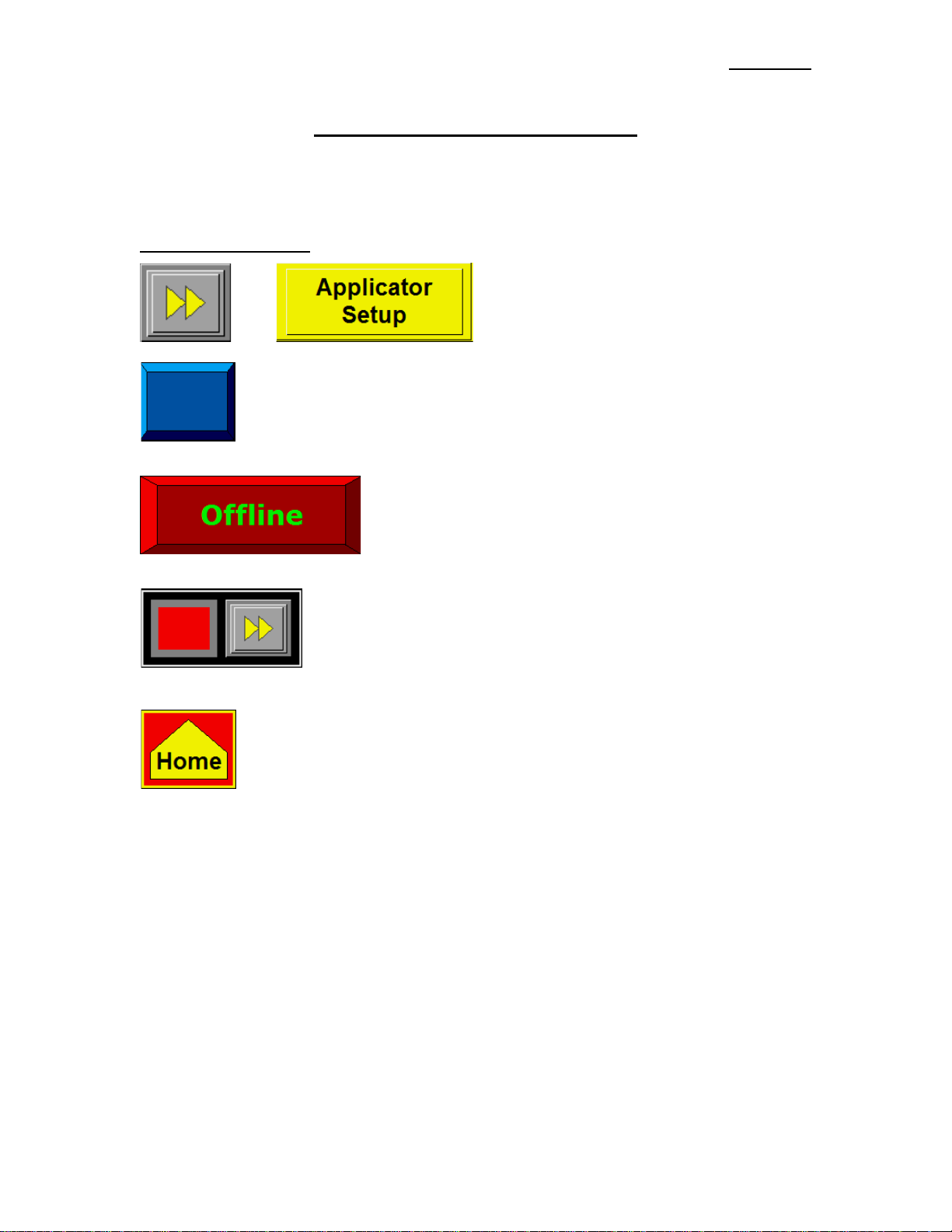
TYPES OF KEYS
Or are “go to” keys and will move the operator to
another screen.
This key is for setting something like an Applicato r Type, jog or us ed as an Alarm Reset
Key. The color of keys will vary depending on the application.
This key is for bringing the Applicator on and offline. When offli ne,
it will be as what is shown to the left, b ut when the App lic a tor is
online, it will be green with red le tte r s.
This block of keys usually turns something on or off. If the option is on, the
lamp to the left of the keys will be gre e n; o therwise it will be red.
This key will take you to the Main Menu even if you are in a setup screen.

360a DISPLAY
3-2
ALARMS
There are two types of alarms generated in the 360a Applicator:
Warning Alarm
Critical Alarm
Warning Alarm Status Box Critical Alarm Screen
Warning Alarms will appear in the upper right hand corner of the Main Menu in the Status Box. Since
these alarms are not serious, the Applicator will not be stopped. During a Warning Alar m, the amber light
on the Light-Stack (if provided) will be turned on.
Critical Alarms will stop the Applica tor (take it offline) and turn a red light on in the Light-Stack (if
provided). The Alarm Screen will cover the current screen explaining the alarm type. An Alarm Reset
button appears at the bottom of the page to clear the alarm.
Warning Alarms
The following are Warning Alarms monitored by the Applicator:
Inhibit – This alar m occurs when an external device inhibits the Applicator from dispensing a label by
activating the Inhibit Input on I/O Connector C2-12.
Tight Loop - If the Loose Loop Option is on and t he Alarm Prox (upper Prox) turns on, this alarm occurs
causing the Applicator to stop applying lab e ls u ntil the Lower Prox turns on. There is no Reset Button
for this alarm since the Loose Loop Program controls whether the Applicator is functional or not.
Although the Applicator is stopped , this is still considered a Warning Alarm since the Applicator will
resume labeling as soon as the Printer catches up with the Applicator. The Tight Loop Status Bo x will
have a red background instead of yellow to signal the alarm condition.
Low Label – This alarm occurs when the Low Label Sensor detects that the unwind roll is nearly out of
labels.
Multi-Label C-C Distance Is Too Low – This alarm occurs when the Multi-Label Opt ion is on and the
Applicator cannot place labels at the desired Center-line Distance. If the application permits, increase
the Label C-C Distance to correct the problem. For Non-Merge Applicators, you can try increa s ing the
Web Speed value or decreasing the conveyor speed value. In Tamp Applicators, reduce the Tamp
Extend/Retract Ti mes to the minimum. In Air-Bl ow Applicators, reduce the Air Blast Time to the
minimum and increase the Pre-Dispense Time if possible. In Merge applications contact the factory
concerning appropriate Accel and Decel values for your application.
DAT Label Pla cements Are Too Close – If the Applicator Type is a Dual Ac tion Tamp and the Second
Label Placement is low enough that the second label is not out onto the Pad before it should be applied,
this alarm will occur. Increasing the Second Label Placement will correct the problem. This also
could be viewed as a rate alarm.
Conveyor Speed, Profile or OverSpeed % Too High Compared To MaxSpeed - This alarm occurs on
Merge Encoder-Based Applicators when the conveyor speed or the product of conveyor speed times
the Profile or Over Speed % yields a speed greater than MaxSpeed. If possible, decrease the conveyor
speed or increase the Applicator’s MaxSpeed value. In Over Speed or Profiling app lic a tions try
decreasing the Pre-Apply Speed % or WebRatio % values respectively.
360a DISPLAY
3-3
ALARMS (cont’d)
(WARNING ALARMS)
Label Placement is Too Low – This alarm occurs in Encoder-Based
distance is too small for encoder compensation to work correctly. During label placement a speed
dependent distance is subtracted from the label placement value to pr operly position the label. If this
alarm occurs, move the Product Detect Sensor upstream more, decrease the conveyor speed, or
increase the Label Placement value.
Profile Or OverSpeed % Too High Compared To MaxSpeed – This alarm occurs in Merge Time-Based
applications when the Profiling or Over Speed % times the Web Speed value yields a speed greater
than the MaxSpeed. If possible, decrease the conveyor speed or increase the Applicator’s MaxSpeed
value. If possible, decrease the Over Speed Pre-Apply Speed % or the profiling WebRatio % values.
Imprint Dwell Too High For Label Cycle – This alarm occurs if the Imprinter Valve is on when the
Applicator is ready to dispense a label to the product, Air-Blow Grid, or Tamp Pad. For Merge
applications, no label will be dispe nsed . Air-Blow and Tamp Applicators will wait for the Imprint
Dwell to timeout before dispensing a label to the Grid or Pad.
Critical Alarms
The following are the critical alarms monitored by the applicator:
End Of Web – This alarm occurs when the End Of Web sensor detects a break in the web.
No Labels Found – This alarm occurs if the number of consecutive missing labels on the liner exceeds the
Missing Label Count value. If a No Labels Found Alarm occurs when labels are present on the liner,
re-teach the label sensor sensitivity settings.
Printer Not Rea dy - This alarm occurs when the Printer is paused while the Applicator is controlling a
Printer in a Loose Loop format with the Printer Ready Input Signal active.
applications when the Label Placement
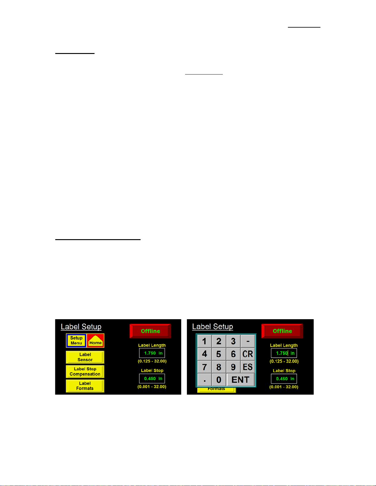
CHANGING VALUES
Values that may be changed are shown in boxes displaying the current value. In the example below, label
length is shown to have a value of 1.75”. To change this value, the operator will touch the screen in the
label length field and a keypad will appear to the side of the variable being changed. The figure to the right
shows wha t the Displa y should look like after t ouching the variable field. You can see a cursor has moved
over the rightmost digit. Also the numeric keypad has appeared to the left of the variable. As you touch
numbers on the keypad, the variable is zeroed and the new value is input to the variable box. Pressing
“ENT” will finish the process. Pressing “ES” will allow you to escape without changing the value and
“CR” will clear the value you’re changing. Note: In most cases, an out-of-range value w il l not produce
a warning message but the variable will return to the original value after pressing “ENT”.
3-4
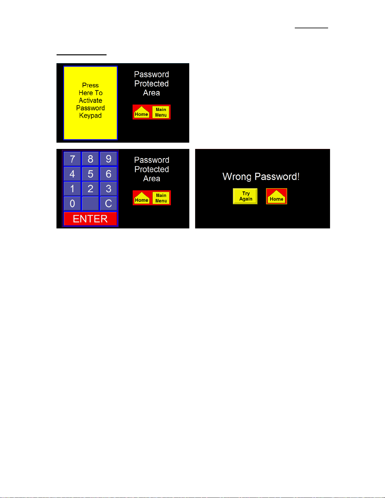
PASSWORD
360a DISPLAY
The Setup Section of the Display is password
protected. The Standard 360a password is “1800”.
When you get to a passwor d-protected area, a screen
similar to the one to the left will appe a r.
This screen notifies the operator that the area is
password protected. Here the operator can choose
to go back to the Main Menu or co nti nue wi th
password entry by touching within the box to the
left to activate the keypad
When you touch a number on the keypad, it will
highlight. This is the only indication that a key
was pressed since the password is not displayed.
If you know you’ve enter ed a wrong number,
press “C” to clear what you have and start again.
“ENTER” finishes the process.
If the wrong password was entered, the screen above
appears. If the operator wants to try again, press the
“Try Again” key. If you do not know the password,
press the other key to go to the Main Menu.
360a DISPLAY
3-5
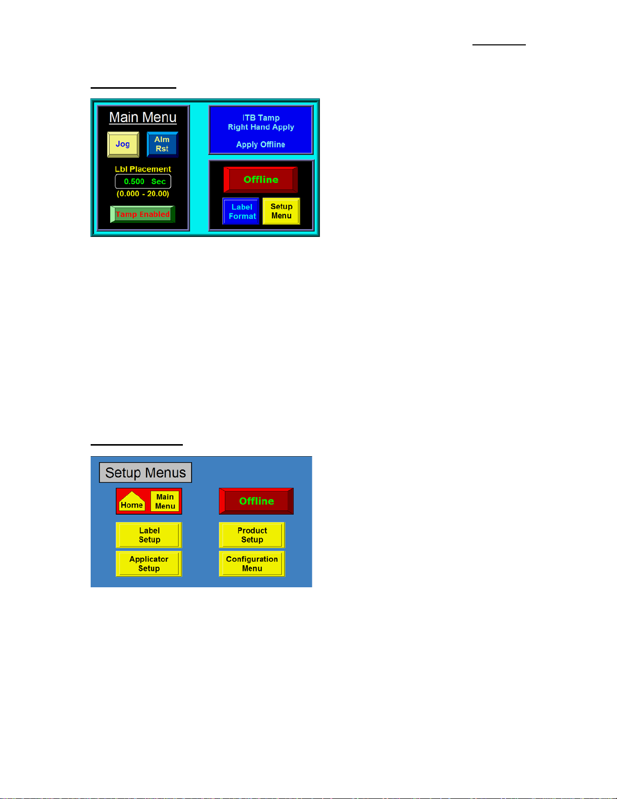
MAIN MENU
The Main Menu is divide d into three sections.
The upper right corner of the Display is a Status
Window. The purpose of this box is to inform
the operator of the status of the Applicator. The
display shown to the left appears immediately
after going offline. If the Applicator is online
with no alarms, the Status Windo w will have a
green background with the label rate displayed.
If a Warning Alarm occurs, the background
changes color and a message will appear
indicating the nature of the alarm. Specific
Warning Alarms were discussed previously.
The left side of the screen will change based on Applicator Type. There will always be Jog and Alarm
Reset keys and access to Label Placement.
The lower right corner has buttons to place the Applicator on and offline and keys to take you to the
Formats and Setup Menus. Plac ing the Applicator o nline applies power to the Drive Motor and arms the
Applicator for labeling. The Format Key gives access to the operator to load a saved Format. The operator
cannot change or erase Formats from here. The Setup Key takes the operator to a password-protected area
to make changes to the operation of the Applicator.
The Display is equipped with a backlight saver function that a utomatically turns off the backlight after 60
minutes of inactivity. Pressing a ny part of the Display will turn the backlight on again. Also, the
Applicator will initiate a backlight wake-up in response to any Critical Alarm condition. The later feature
insures that the operator has a visual indication of a Critical Alarm condition in systems without a LightStack Assembly.
SETUP MENU
Because the Setup Menus are password-protected,
pressing the Setup Key at the Main Menu wi l l
cause a password screen to appear. By entering the
correct password will cause the Setup Menu to
come up. From here the operator can go to the
different setup sections. The operator can also
bring the Applicator online while he changes the
setups. Once the Applicator is set up and the
operator exits the Setup Menu, the Applicator will
save the new s ettings. If power is cycled to the
Applicator before the Display is r e turned to the
Main Menu, the new settings will not be saved.
Note: You must be offline to enter the
Configuration Menu.
360a DISPLAY
3-6
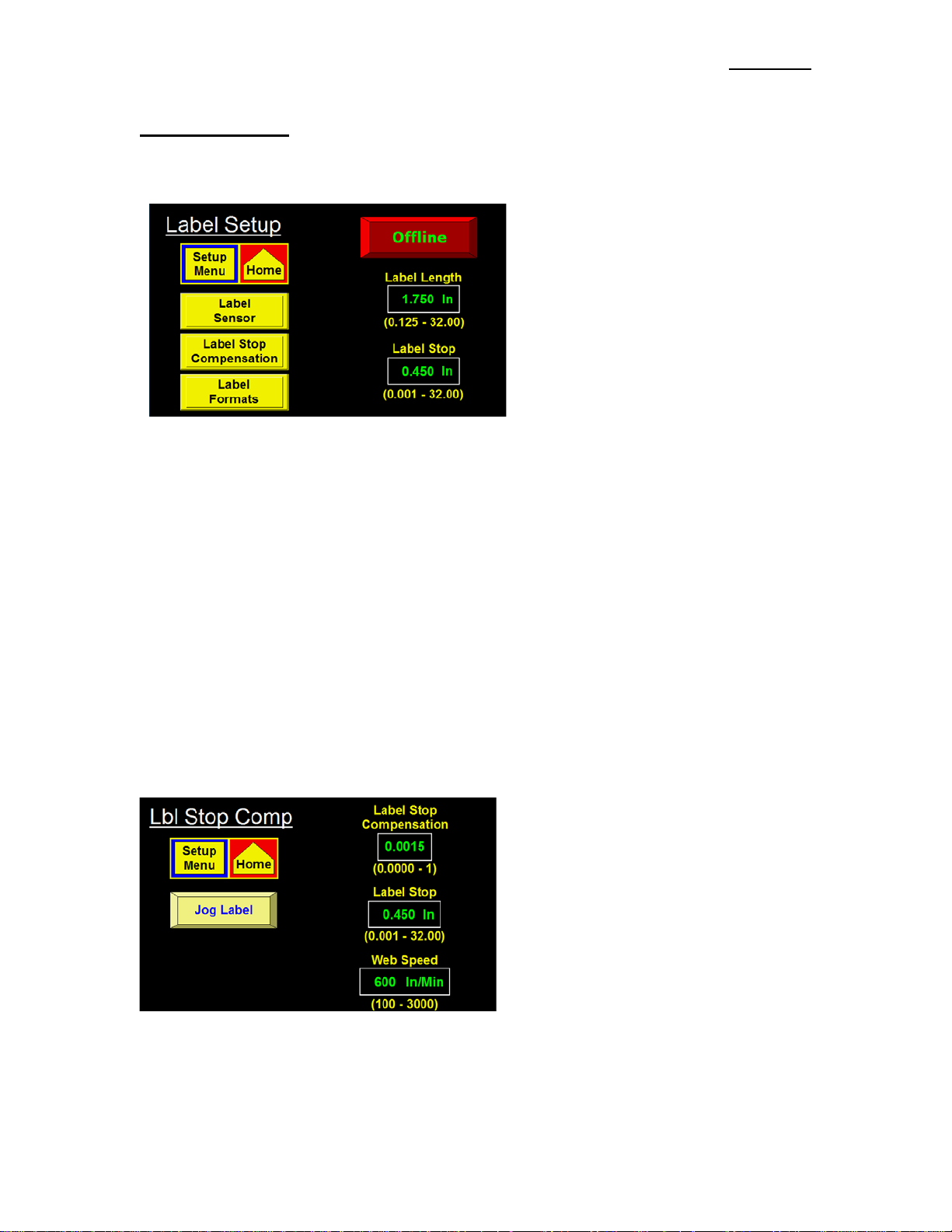
LABEL SETUP
The Label Setup menu is accessed from the Setup Menu by pressing the Label Setup Key. The label setup
section gives the operator access to variables on the Applicator that pertain to the label.
The following items may be changed in this
section:
Label Stop
Label Length
Label Sensor Setup
Label Stop Compensation
Label Formats
Label Length -The label length is defined as the feed length of the label plus the width of the gap between
labels. Stated another way, it is the distance from the leading edge of one label to the leading edge of the
next label. Since each application cycle moves the label length distance, it is important to enter the exact
label length value. Allowed values are between 0.125-32”.
Label Stop -The Label Stop b o x lets you enter the label stop distance value. The Label Stop value is the
distance from the label edge to the Label Sensor. Allowed values are between 0.03” and (label length –
0.06”). The Label Stop value may be changed while the Applicator is running.
Label Stop Comp –Although very rare, we have found the Label Stop would vary with Web Speed when
running certain types of labels. This seems to do more with narrow labels and the materials used to convert
them. Label Compensation is normally fixed but when Label Sop is moving with Web Speed, it was found
making changes to it can make the labe l stop position better. Label stop compensation is a number that
shortens the Label Stop value the higher the Web Speed. This corrects the problem of the label position
creeping out the faster the Web Speed.
Note: This option is only for Encoder-Based Merge Applicators
Label Stop Comp Setup
Before setting this up, make sure the Label Sensor, Label Length, Label Stop and Max Speed have all been
setup. It is also important the Encoder Variables are correctly setup.
The default value for Label Stop Comp is
0.0015. Set the Web Speed to the slowest speed
the product will be traveling (let’s say 500
in/min). Use the Jog Key on the Display or the
Jog Switch o n the Applicator to dispense a
couple of labels. Take note of where the label
stops. Now change the Web Speed to the
fastest the product will be traveling and jog a
couple more labels. If the Label Stop position
moved forward, increase the Label Stop
Compensation. If the Label Stop moved back,
decrease the Label Stop Compensation. It is
unlikely that the compensation value will be less than 0.0015. If you can change Web Speeds and the
Label Stop holds pretty well, you are finished. If needed, you can make adjustments to the label stop
position so the Label Stop is back where you want it. When you exit the Label Stop Compensation screen,
the Web Speed will return to the value set in the Applicator Setup Menu.

360a DISPLAY
3-7
LABEL SETUP (cont’d)
Label Sensor -Pressing this key will bri ng up
the Label Sensor Menu. This is where the
sensitivity of the Label Sensor is setup. The
operator will have two choices:
Auto Teach
Manual Teach
Manual Teach
In the Manual Teach Mode, the opera tor will
first choos e whether they want to trigger on the
leading or trailing edge of the labe l. The only
reason for c hanging edges occurs when the
Label Stop is either too small or too close to the
Label Length. After selecting an edge detection
mode, the Display will provide opera tor
instructions at the bottom of the scree n. For
example, if leading edge is selected, the Display
will prompt the user to move the label and liner
under the Label Se ns or and pre s s the Teach Key
on the screen. After a couple of seconds the user is prompted to move the liner under the sensor. Move the
label stock by turning the Drive Roller to place the label gap under the sensor or remove a label. Again the
operator will press the Teach Key. After a couple of seconds the process is finished. The operator can
return to the Label Setup Menu by pressing the “Prev Menu” Key.
Auto Teach
The Auto-Te ach function not only sets the
Label Sensor Sensitivity but also calculates the
Label Length and Label Stop values. When the
Auto-Teach function is selected, the operator is
prompted to move the label gap under the
sensor. Pressing the Teach Key causes the
Applicator to dispense 10 inches of labels while
setting the Label Sensor Sensitivity.
Key is provided to skip the sensitivi ty setup for
instances where the sensitivity is known to be
correct or when a Clear Label Sensor is
installed. Following the sensiti vity setup, the
operator is prompted to move the label to the Label Stop Position and press the Teach Key. Three labels
are dispensed while calculating the Label Length and Label Stop values. If the Multi-P anel Option was on,
an extra screen appears instructing the operator to move a label to the Peel Edge to allow the controller to
calculate the Short Feed Distance. This will be discussed in more detail in the Applicator Setup section.
NOTE: The Label Sensor output lamp will be a light blue when the sensor is on. If the sensor i s se t
to “Leading”, the light will be on when the la be l is unde r the sensor. If “Trailing ”, the light will be
on when the gap is under the sensor.
NOTE: See SPECIAL OPTIONS section for information regarding the Label Sensor Mode l setting if
the Applicator is not responding correctly to label teach routines.
A Bypass
360a DISPLAY
3-8
Main Menu Format Screen
Main Format Screen
LABEL SETUP (cont’d)
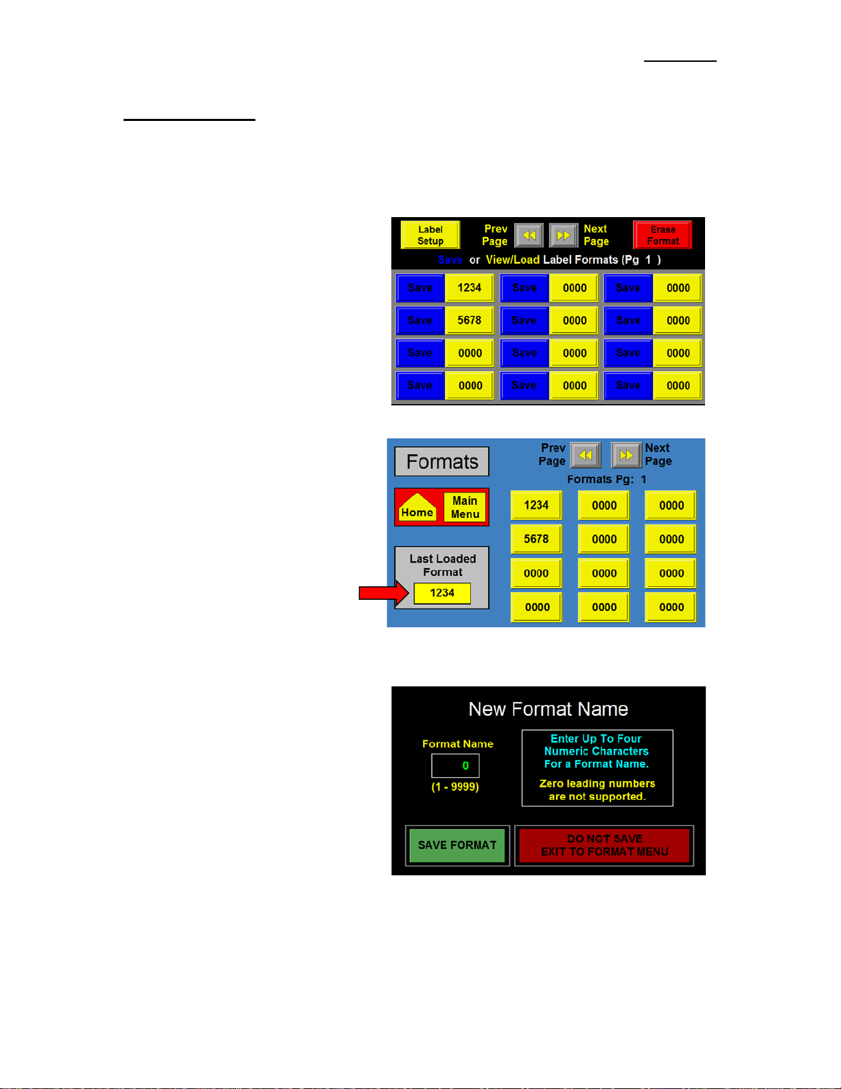
Label Formats
This section allows the operator to save and load configuration setups for up to (48) different products and
labels. This is useful if a customer is running several different products or labels over and over.
Note: The Label Format Key at the Main Menu only allows the operator to only load Formats.
A format saves the following parameters:
Label Placement Encoder Option
Label Length Pulse Length
Label Stop Compensation
Detector Lockout Air Blast Time
Web Speed Ext. Air Assist
Slew Speed Tamp Extend
Max Speed Tamp Retract
Accel Pre-Dispense
Decel
Options and Variables
Consult factory for a complete list of
Parameters saved.
This screen will show the last Format
loaded. If no Formats had been loaded,
the value in t he box would be “0000”.
Saving a Format
If the curre nt setup in the Applicator is
performing correctly and you wa nt to save it,
press “Label Formats” in the Label Setup
Menu. When a “Save” key is pressed, the
Applicator will check to see if a Format
already exists in the location selected. If it
does, the operator will be prompted whether
or not to overwrite its contents with the new
information. If the name is “0000”, the
operator will be asked to enter up to four
digits for the Format Name. Pressing the
green Save Format key, saves the Format to
the name shown in the Format Name box
provided the name is not already used for another Format. If it is, the system prompts the user to sele c t a
different na m e. Pressing the red Exit Key on the screen allows the operator to exit without saving the
Format.

360a DISPLAY
3-9
LABEL SETUP (cont’d)
Viewing/Loading a Format
When the operator wants to view/load a Format File, they need to press the yellow portion of the key
associated with the desired Format name. If the number is “0000”, no Format is saved in that location.
Selecting a “0000” Format will cause a screen
to appear with a “No File Found” message.
Pressing the View/Load Ke y will not
immediately load the Format but will allow the
operator to view the values within that Format.
After reviewing the values, the operator may
press “Load Format” to load the Format. If th e
wrong format was selected, the operator can
press the “Exit W/ Out Cha n gi ng” key.
Deleting a Format
When the operator wants to delete a Format
that currently exists, pr ess the Erase Format
Key in the upper right hand corner o f the
Display. The screen to the right will appear.
Pressing any of the bo xe s with a name will
cause that Format to be erased.
Note: There is no second step to this
operation. Once you press the format box,
the Format will be erased.

360a DISPLAY
3-10
APPLICATOR SETUP
The Applicator Setup Menu is accessed from the Setup Menu by pressing the “Applicator Setup” Key. The
screen is split into upper and lower sections. The upper part does not change and allows the operator to
return to the Main or Setup Menus and place the Applicator on or offline. The lower section of the screen
changes based on the Applicator Type selected.
Depending on the Applicator Type, the operator has access to the following variables:
Tamp/Swing Extend and Retract Times
Air Blast Time
Extended Air Assist Time
Web Speed
Pre-Dispense
Label Profile Configuration
Multi-Panel Option
Over Speed
The following serves as an explanation for each
section.
Air Blast -The Air Blast Time is the interval of ti me that the Air Blast Valve is turned o n. Allowed values
are .005 - 1 second.
Tamp Extend -The Tamp Extend Time is the interval of time allotted for the Tamp Slide to extend. After
the timer has timed out, the Air Blast will occur and the Tamp Slid e will return home. To keep labeling
speeds up, this value should be as low as possible. Allowed values are between .01 - 5 sec.
Tamp Retract -The Tamp Retract Time is the interval of time allotted for the Tamp Slide to return home
before feeding another label. If this value is too small, a label will feed into the Pad or Manifold. Allowed
values are between .01 - 5 seconds. Note: In a Tamp Applicator, the Tamp Slide action may be
disabled or enabled by pre ssing the “Tamp Enabled/Disabled” Keys.
Extended Air A ssist -The Extended Air Assist Time is the interval of time after the label feed until the Air
Assist is turned off. It is used in Air Blow and Tamp Applicators to help hold the label in place on the Grid
or Pad prior to being blown onto the product. Allowed values are between .000 - 1 sec.
Web Speed -The “Web Speed” Key allows the opera tor to enter the Applicator Web Speed value. Allowed
values are between 100 and 3000 ”/min with the upper limit depending on the Max Speed setti ng in the
Configurati on Menu. The specific limits are shown above the current Web Speed value. The Web Speed
value may be changed while the Applicator is running.
Pre-Dispense –This is the amount of time before the Air Blast turns-off that the Applicato r begins the label
dispense. This Option applies only to A ir Blow Applicators and will speed-up the application rate. If
the value is too high, the Applicator will start disp e ns ing a label into the Air Blast stream causing the label
to fall off the Grid. Ideally, the Pre-Dispense time allows th e Applicator to get past the label Accel curve
and place the label at the edge of the air stream when the Air Blast Valve turns off.

360a DISPLAY
3-11
APPLICATOR SETUP (cont’d)
Over Speed – The Over Speed Option allows a Merge Applicator to get up to Web Speed faster by
dispensing the “Pre-Apply Feed” distance at the (Pre-Apply Speed % x Web Speed). In Multi-Label mode,
this will help place the labels closer together. Not e: This Option is only for Merg e Applicators.
(Over Speed Screen)
(Over Speed Help Screen)
Note: The Help Screen will note what Functions are disabled when this Function is turned on.
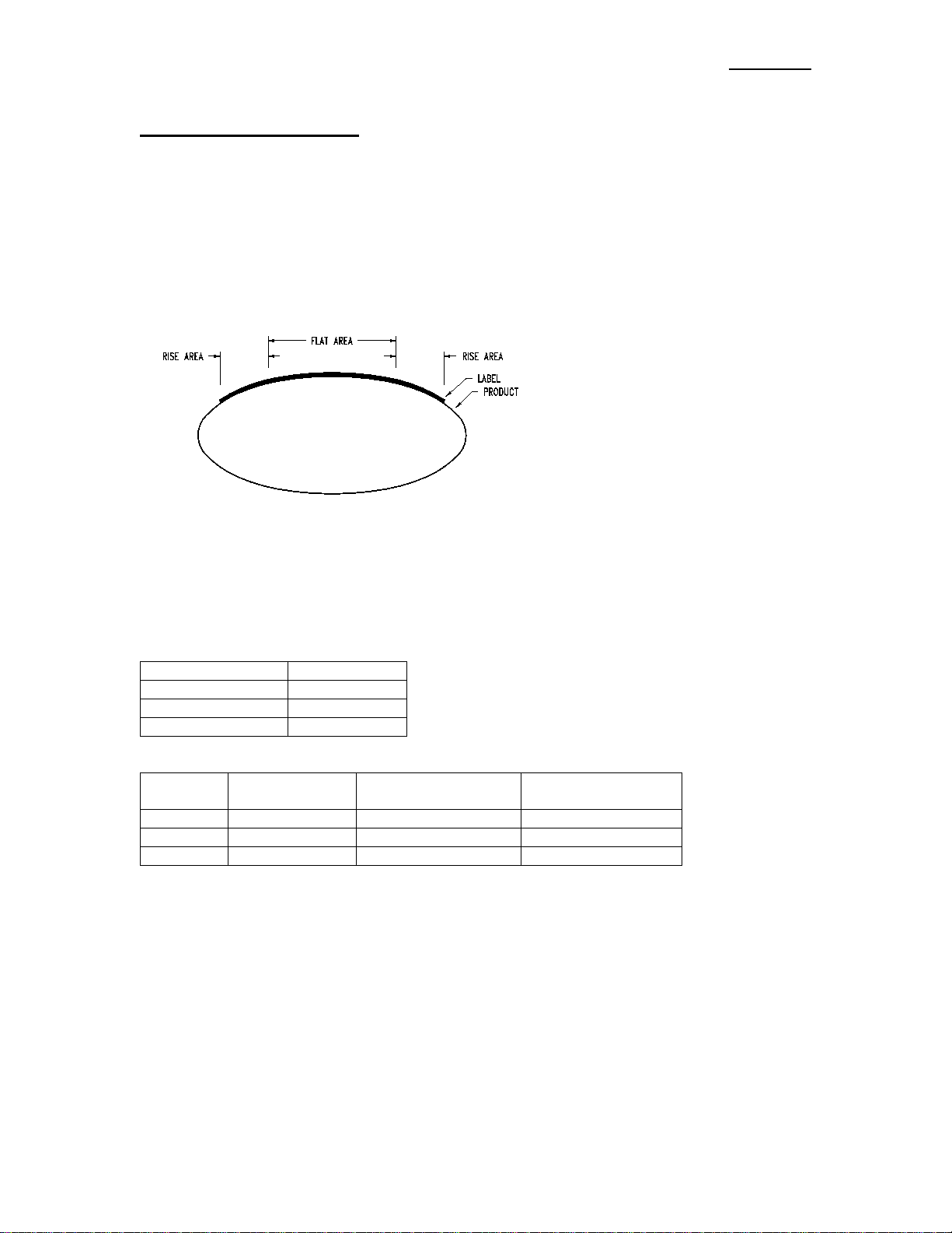
Label Profile -Profiling is a Merge only Option used to aid in labeling products that have a concave or
convex surface. If the surface of the product is convex and the web ratio is less than 100%, t he Applicator
will dispense a label at Web Speed during the “Rise Area” distance. After the “Rise area” distance, the
Web Speed changes to (web speed) x (web ratio) during the “flat area” distance. After traveling the
combined “rise” plus “flat” distances, the Applicator returns to Web Speed for the remainder of the move.
The reaso n for this action is that convex pro ducts start o ut farther away from the Peel Edge than it will be
by mid-product. The label is dispensed at normal speed at the beginni ng of the pr oduct. As the product
surface moves closer, the label must slow down so that the labels do not wrinkle. As the product surface
moves away, the label speeds-up. On concave products the label is dispensed at Web Speed initially. As
the surface of the product moves away, the label is dispensed faster to force the label into the product (Web
Ratio>100%). The label dispense speed is slowed as the product surface moves closer to the Peel Edge.
NOTE: 1) Label Profiling is a function of the Merge Applicator only.
2) Label Profiling is enabled when the “Web Ratio” is set to something different than
“100%”.
3) Max Speed for the Applicator is setup in the Configuration Menu and will range from 100
to 3000 in/min. If the Applicator exceeds the Max Speed “Conveyor Speed, Profile or
OverSpeed % Too High Compared To MaxSpeed” Warning Alarm will occur. The
Applicator will not exceed this speed even if the Web Ratio is set to a higher number.

360a DISPLAY
3-12
APPLICATOR SETUP (cont’d)
(LABEL PROFILE)
(Profile Screen)
(Profile Help Screen)
Note: The Help Screen will note Options that are incompatible with the Profiling
Option.
Profile Variables
Rise Area -This is the distance the label travels before chan ging to the mid-product labeling speed. Enter a
value between 0.1 and 20. The Applicator will be running at Web Speed during this distance.
Flat Area -This is the distance the label tr a vels while at the mid-product labeling speed. Enter a value
between .1 and 20. The Applicator will be running at a percentage (Web Ratio) of the Web Speed dur ing
this distance.
WebRatio -The Web Ratio is a scaling percentage applied to the Web Speed or conveyor speed value to
either slow-down or speed-up the Applicator during the Profile Flat Area. This nu mber will va ry
depending on product shape and is usually determined by trial and error. Enter a value between 50% and
150%.
360a DISPLAY
3-13
Condition
Product Shape
WEB RATIO < 100
Convex
WEB RATIO = 100
Flat Surface
WEB RATIO > 100
Concave
Web Ratio
Setting (%)
Speed during
0” to rise distance
Speed during
rise to flat distance
Speed during flat
to label length distance
< 100
web speed
(web speed) (web ratio)
web speed
= 100
web speed
web speed
web speed
> 100
web speed
(web speed) (web ratio)
web speed
APPLICATOR SETUP (cont’d)
(LABEL PROFILE)
Estimating Rise and Flat Areas
This process will give you a starting po int for setting Profile Variables. Some experimentation is necessary
for best results. The example shown is for a convex or oval product.
1. Apply a label by hand to the product. Measure the Rise Area by looking at the beginning of the
label to where it starts to flatten out. Also measure the length of the Flat Area. Use the diagram
below as an example.
2. Use these numbers when inputting values to the Display.
3. When using this type of product, Web Ratio is set less than 100%. This will slow the Web Speed
during the Flat Area.
PROFILING SUMMARY

360a DISPLAY
3-14
APPLICATOR SETUP (cont’d)
(LABEL PROFILE)
Rise Area and Flat Area Final Adjustment
The system will wor k best with the smallest Rise Area value and the largest Flat Area value that properly
applies the label. Use the instructions below to find these values.
1. With the Applicator online, send several products down the conveyor and observe the labels that
are applied.
2. If the leading edges of the labels were all applied at the same position on the products, go on to
step #3.
If the leading edges of the labels were placed at various positions on the products, the Rise Area
Length is too short.
Slightly increase the Rise Area Length and run some more products. Repeat until the leading edge
label placement is consistent.
3. If the leading edges of the label were applied at the required position on the product, go on to step
#4.
If the leading edge of the label is applied at the incorrect position, adjust the “LABEL
PLACEMENT”, or re-position the product detector. Run some more products. Repeat until the
leading edge of the label is applied a t the r e quired position on the product.
4. If there are no wrinkles or bubbles in the first half of the applied labels, go on to step #5.
If a wrinkle or bubbles appear from the top to the bottom of the first half of the label, the Rise
Area is too long.
Slightly decrease the Rise Area and run some more products. Repeat until the wrinkle in the first
half of the label is removed.
5. If there is no wrinkle in the center of the label, go on to step #7.
If a wrinkle appears from the top to the bottom at the center of the label, either the Web Ratio is
too high, or the Flat Area is too shor t.
The W e b Ratio will be adjusted first. Before adjusting, note the Web Ratio setting. Slightl y
decrease the Web Ratio and run some more products. Repeat until the wrinkle is removed. Go on
to step #7.
6. Increase the Flat Area slightly and run some more products. Repeat until the wrinkle is removed.
7. If the labels are applied wrinkle free from lead edge to trail edge, go on to step #8.
If small horizo ntal wrinkles appear on the trailing edge on the label, the Flat Area is too long.
Slightly decrease the Flat Area and run some more products. Repeat until wrinkles are eliminated.
8. When the Web Ratio, Rise Area and the Flat Area are established, the setup is complete.
360a DISPLAY
3-15
A
B
E
D
C
APPLICATOR SETUP (cont’d)
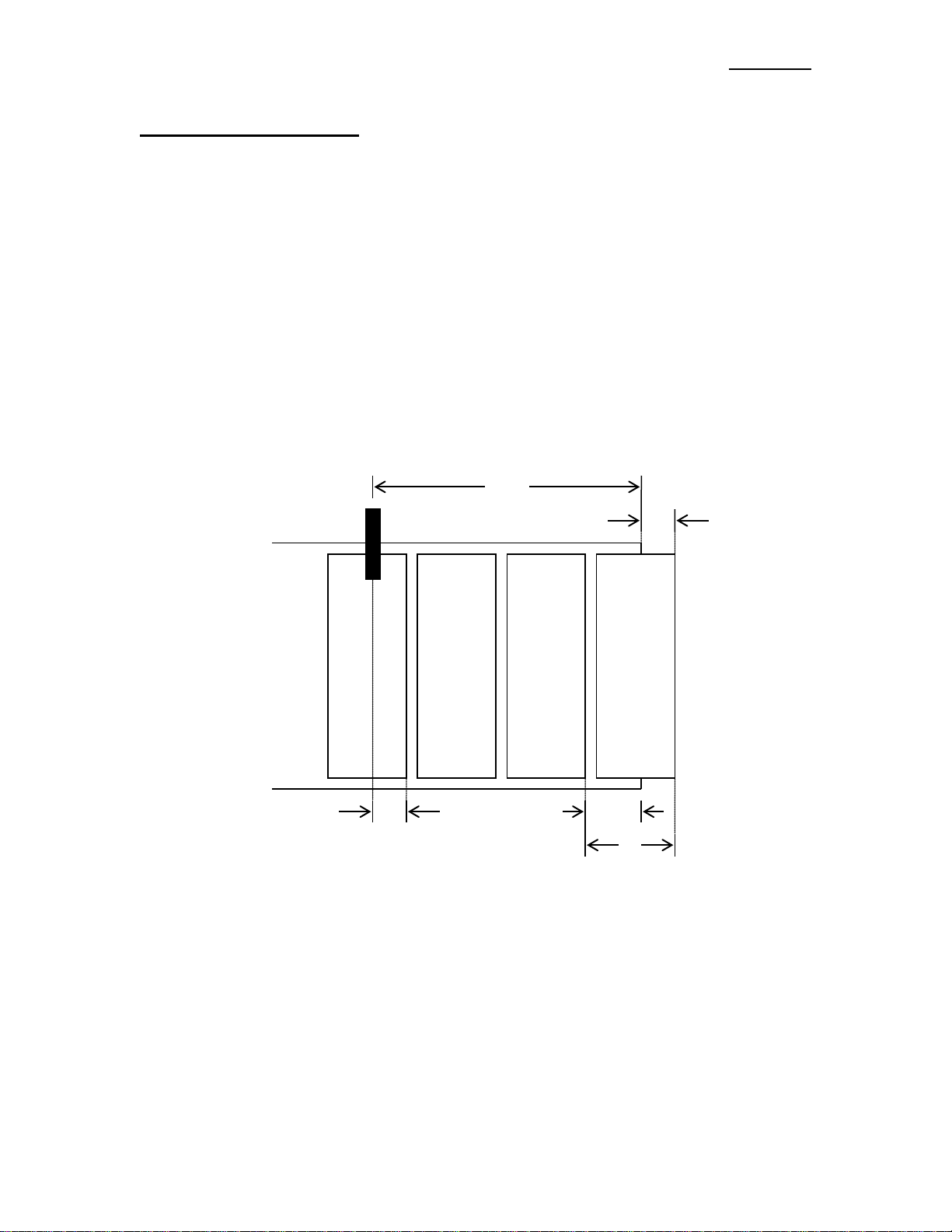
Multi-Panel Apply
The Multi-Panel Apply Option is used to merge a label onto two or three panels of a product. An example
might include the leading, top, and bottom panels of a clamshell container. The Applicator is initially setup
so that the label is flagged out in fro nt o f the product but is still supported on the liner. When a product
detect signal is received, the Ap plicator will wait for the Label Plac e ment distance. At Label Placement,
the Applicator will feed the “Short Feed Distance” at encoder speed. This will place the next label at the
Peel Edge. The Applicator will wait for the “Product Clearance” distance to allow the product to pass by
the Peel Edge before moving t he next label to the flagged out position (Label Stop ) a t Slew Speed. The
figure below illustrates an example se tup with four labels between the Peel Edge and the Label Sensor
along with the measurement definitions:
A: label sensor to peel edge distance
B: label length
C: label flag distance
D’: label stop distance with C = 0 ( no t shown)
D: label stop distance
E: short feed distance
When the Multi-Panel Option is turned on, the user is prompted to go to the Label Setup Menu and perform
a Label Sensor Auto Teach operation. The Auto Teach feature will calculate all of the dimensions shown
above if the option is enabled prior to running auto teach. The operator may override these settings by
measuring values B through E above and enteri ng them via the Display. Note: Since the Multi-Panel
Apply Option is distance based, the Encoder Option must be purchase d.

360a DISPLAY
3-16
APPLICATOR SETUP (cont’d)
(MULTI-PANEL OPTION)
(Multi-Panel Screen)
Note: The Help Screen will note Options that are disabled when this Option is turne d on.
Configuring Mult i -Panel Apply With Auto Setup
1. Make sure the Applicator is powered up and offline.
2. Perform the Encoder Setup procedure outlined in the Product Setup section.
3. Press “APPLICATOR SETUP” and select “MULTI-PANEL”
4. Toggle t he Option on.
5. Enter the distance after the label is dispensed to when the product clears the Peel Edge to the
6. Go back to the Main Menu and press “LABEL SETUP” then “LABEL SENSOR”
7. Select “AUTO SETUP” and follow the screen prompts (see: AUTO TEACH on page 3-7).
Configuring Mult i -Panel Manually
1. Make sure the Applicator is powered and offline.
2. Perform the Encoder setup procedure outlined in the Product Setup section.
3. Using the hand wheel, position the label in the flagged out position.
4. Under “LABEL SETUP”, enter the distance measured for dimension D shown above. Note: If the
(Multi-Panel Help Screen)
Product Clearance box. The distance should be approximately equal to the product length.
Label Sensor is set for trailing edge de te c tion, add the label gap distance to di mens ion D.

360a DISPLAY
3-17
APPLICATOR SETUP (cont’d)
(MULTI-PANEL OPTION)
5. While in “LABEL SETUP” enter the Label Length measured for dimension B.
6. Under “APPLICATOR SETUP”, press the “MULTI-PANEL” button and turn the Option on.
7. Set the Short Feed to the distance measured for dimension E.
8. Enter the distance after the label is dispensed to when the product clears the Peel Edge into the
Product Clearance box. The distance should be approximately equal to t he product l ength.
Note: During the last part of the di spen se cycle (after the product clears the Peel Edge), the label is
dispensed at Slew Speed . This is usually faster tha n the Web Speed and is set in the
Configuration Menu.
PRODUCT SETUP
The Product Setup Menu is accessed from the Setup Menu by pressing the “Product Setup” Key.
The following parameters may be changed or
monitored in this section:
Label Placement(s)
Detector Lockout
Encoder Speed (monitor)
Encoder Option
Label Placement -The Label Placement box lets you change the Label Placement value. Label Placement
is the time or distance from the Product Detect Sensor to where the label is dispensed onto the product. If
the value entered is out-of-range, the previous value will be restored after the “ENT” key is pressed. The
allowed range of values, in seconds if time based o r in inches if encoder based, are shown below the Label
Placement Box. The Label Placement value may be changed while the Applicator is running.
Note: This Label Placement parallels the Main Menu and is located here so that the operator
can do their setups wit hout exiting to the Main Menu.
Detector Lockout -The Detector Lockout functi on is used when more t han one product detect signal is
generated per product. If the Encoder is on, Detector Lockout is in inches; if there i s not an Encoder then i t
will be in seconds. The Lockout starts at the begin ning of a labeling sequence and the Applicator will
ignore Product Detect Signals until the lockout time or distance is finished. Allowed values are between
.001 – 200 inches or seconds.
Encoder Speed -Thi s box displays the conveyor velocity obtained from the Encoder Signal connected to
the Applicator’s Encoder Port. The value displayed is the number of (pulses/min from the encoder) x (the
pulse lengt h in inches/ pulse).
Encoder Option -The Encoder Option is useful when the product veloc ity varies during the applicatio n
cycle. An example of such an ap plication is a Merge Applicator on a Forms Table. With the Encoder
installed and enabled, the Applicator adjusts the label dispense speed to insure accurate label placement on
the product.

360a DISPLAY
3-18
PRODUCT SETUP (cont’d)
(ENCODER OPTION)
The Applicator has a differential quadrature incremental encoder interface with times four interpolation
built into the controller board. The Encoder Connector, located on the rear panel, has 5 VDC supply to
power the Encoder. The Encoder wiring diagram and pin-out information appear in the drawings section in
this manual and should be consulted for user supplied encoders. Factory encoders generate 2500 pulses per
revolution.
The following parameters may be changed
or monitored in this section:
Encoder Filter
Encoder Option On/Off
Encoder Speed (monitor)
Pulse Length
Compensation
Encoder Filter – In some applications, the Encoder speed varies significantly around some average value.
This is especially problematic with Merge applicators, low-resolution Encoders and low conveyor speeds
where fewer encoder pulses are captured during the velocity calculation interval. The Encoder Filter
function allows the operator to average the Encoder Speed over a range of 1 to 10 scans to produce a
smoother label dispense. As with all filters, the response of the App lic a tor to the change in Encoder Speed
is proportional to the number of Scans. The lower scan numbers are more responsive to speed changes
while the higher number produces a smoother/quieter application with more power in the Merge
Applicator. In applications suc h as Forms Tables, where the conveyor performs start/stop moves, a lower
scan number is appropriate. In constant conveyor speed applications, a scan number closer to 8 may be
more suitable. In all instances, the performance of the system should be verified under a variety of
conditions.
Encoder Option –The Encoder Option Ke ys are for turning this Option on and off. If the Option is on, the
lamp to the left of the keys will be gre en. When the Encoder is on, Label Placement is in inches and not
seconds.
Pulse Length -The distance the product travels per pulse of the Encoder. T he pulse length may be
calculated using the following formula:
Pulse Length = (Distance Product Moves / Rev) /
((Encoder Pulses / Rev) x 4)
EXAMPLE: An Encoder is mounted to a conveyor drive pulley and the circumference of that pulley is
18.75”. Therefore, with one revolut i on of the E ncoder, the product on the conveyor w ill travel 18.75”. The
Encoder is a factory-installed encoder generating 2500 pulses per revolution.
Pulse length = 18.75” / (2500 x 4)
Pulse length = 18.75” / 10000
Pulse length = 0.001875 in/pulse

360a DISPLAY
3-19
PRODUCT SETUP (cont’d)
(ENCODER OPT I ON)
Compensation - Compensation is a number that functions within a formula to reduce the Label Placement
value based on the encoder velocity. When products move faster on the conveyor, the label dispense must
begin sooner to compensate for the acceleration time of the label to the product. The following expla ins
how to setup compensation for the different applicators.
Air Blow and Tamp Compensation Setup
When selecting a value for rate compensation, start at 0.017. Apply labels to the product at a slower speed.
Then run the product at production speeds or faster. If the labels are applied in the same place, the
compensation is correct. If the labels move back at higher speeds, INCREASE THE COMPENSATION.
If the labels move forward, DECREASE THE COMPENSATION. Whenever the rate compensation
value is adjusted, it is advisable to re-run the product at various speeds to make sure that the labels are
applied in the same position.
Merge Compensation Setup
When selecting a value for rate compensation, start at 0.008. Apply labels to the product at a slower speed.
Then run the product at production speeds or faster. If the labels are applied in the same place, the
compensation is correct. If the labels move back at higher speeds, INCREASE THE RATE
COMPENSATION. If the labels move forward, DECREASE THE R ATE COMPENSATION.
Whenever the rate compensation value is adjusted, you should re-run the produc t at slower and faster
speeds to make sure that the labels are a pplied in the same position.
Notes: 1) Label Placement units with the Encode r Option on are in inche s, not seconds.
2) The Encoder Option will not be accurate with a Normal Tamp Applicator.
3) It’s important to make sure that the Applicator is setup pro perly so labels are dispensed
consistently.
4) If product speeds are too fast causing the compensated Label Placement to lag behind the
current Label Placement, a warning will be give n to raise the label place ment value.
5) If the Encoder Option i s t urned off, all of the Enc oder-Based Options will also turn off
automatically. This is sho wn on the Display whe n the Help Key is pressed.

360a DISPLAY
3-20
CONFIGURATION SETUP
The Configuration Setup Menu is accessed from the Setup Menu by pressing the “Confi g Menu” key with
the Applicator offline
Applicator Type -The Applicator Type
function allows the operator to choose the
type of application (Air blow, M erge, Tamp,
or DAT) and whet her it will be in a Left-Hand
or Right-Hand configura tion.
NOTE: If the Apply Hand (Right or Left)
is changed, the user will be forced to cycle
power to the Applicator
There is a Status Box on the right hand sid e of
the screen that displays the current settings.
.
The Configuration Menu provides access to
Applicator: Type Setup, Options, Motion
Parameters, Diagnostics, and the Label Sensor
reset function. The Applicator Setup may be
monitored or changed by accessing the various
submenus.
Applicator Options –It is here that an operator can look to see if an Option is turned on or not. Pressing
the key will take you into the Option’s Sub-menu so that the operator ca n toggle it on/off or set specific
parameters pertaining to the Option. At each Option Sub-menu, there is a Help Key that will direct the user
to a Help Screen that will explain the c urrent Option’s compatibility with other Options and Applicator
Types. The Help Screen will also notify the user if turning the current Option on will change the state of
any other Option or Function.

360a DISPLAY
3-21
CONFIGURATION SETUP (cont’d)
(APPLICATOR OPTIONS)
Loose Loop - The Loose Loop Option allows
labels to be printed and applied from one
system by integratin g a thermal printer into the
web path of the Applicator. As the labe ls exit
the printer, they go around a dancer arm to
maintain web tension. Three (3) Proximity
Switches monitor the dancer arm position. The
loose loop dancer arm assembly should be free
to travel from the “Loose” Loop Prox, past the
“Tight” Loop Prox, up to the “Alarm” Loop
Prox posit ion. In the “at -rest” position, the
lower “Loose” Prox switch is active and the
printer is off. When the dancer arm assembly
reaches the “tight” Loop Prox, the printer begins printing labels. If the upper “Alarm” Prox switch is
active, the Applicator enters a Tight Loop Alarm condition and a “TIGHT LOOP ” message is displayed in
the Status Box on the Main Menu. T he Applicator is inhibited from applying labels until the dancer arm
returns to the lower “Loose” Loop position. When the Applicator is properly set-up under normal
operating conditions, the arm wil l not
360a Applicator is dispensing f aster than what the printer can print. To correct this issue, decrease
the product rate or increase the printer speed. Due to the variety of loop arrangements, the Loose Loop
assembly is a factory-installed item.
This option has not been CE approved.
Imprinter - The Imprinter Option allows a hot
stamp printer to be installed into the web path
of the Applicato r. It is useful in instances
where one line printing or date coding is
required.
There are two modes for the Imprinter. Mode 1
is the original sequence and is used if the
Applicator is controlling the Imprint Valve. The
Dwell Time in this ca s e is how long the Imprint
Valve is turned on. Mode 2 is used when the
Imprinter has its own controller. The Dwell
Value is now the delay the Applicator will wait before looking fo r the Sequence Complete Signal from the
Imprinter. This delay should be close to matching the Imprinter’s Dwell Time. The Help Key will also
explain each Mode at the Display.
This option has not been CE approved.
reach the “Alarm” Prox position. If the “Alarm” Prox is active, the

360a DISPLAY
3-22
CONFIGURATION SETUP
(APPLICATOR OPTIONS)
Crossover – The Crossover Optio n allows for “zero downtime” operation by interconnecting two (2)
Applicators. Both Applicators are placed on the conveyor system one (1) upstream of the other. The
upst r eam Applicator is the “Primary” labeler while the downstream applicator is the “Secondary” labeler.
The Crossover routine has changed after 360a-2c.0.031 progr am version. In the new Crossover routine, the
Secondary still functions the same in that when it gets a signal from the Primary to turn on or off, it will
track the On or Off Distance and change active state. The Primary now will wait for the next Product
Detect signal after it stopped labeling to s t art the Changeover Sequence. The same is true of the
Secondary. If the conditions are set for a “transfer to the primary”, it will wait for an apply cycle before
signaling the Primary to start. This will insure the transitions occur in the same place every time. Also
changed is the Secondary will start labeling if the Primary goes into a Critical Fault or goes offline and will
continue labeling, even if the Primary is brought back online.
Primary To Secondary Example
With the Primary labeling and the Secondary ready to label, if the operator either takes the Primary offline
or it goes into a Critical Alarm, the P r imary will stop labeling and waits for the next Product Detect Signal.
When the Product Dete ct Input turns on, the Primary sends a signal to the Secondary to start the “transfer
sequence.” When the product has traveled the “On Distance”, the Secondary will start la beling. The
operator can now correct the problem with the Primary and bring it back online.
Secondary To Primary Example
If the Secondary is labe ling when the Primary i s brought online, the Primary will not automatically star t
labeling. In the new sequence, the Secondary continues labeling until it is taken offline, Critical or Low
Label Alarm occurs, or the “Transfer” Key is pressed. Taking the Secondary offline or a Critical Alarm
will cause products not to be labeled but if a Low Label Alarm occurs or the Transfer Key is pressed , the
Secondary sends a signal to the Primary to start labeling while it continues to label. The signal o ccurs at
the first apply cycle of the Secondary after the transfer is initiated. The Primary will then look for the next
Product Detect Signal to start labeling again. When it gets the signal, the primary sends a signal to the
Secondary to start the “Off Sequence.” Doing this give s the Secondary a consistent starting point for either
transition s equence.
Main Menu Changes
When the Crossover Option is on, the left side of the Main Menu will c hange. Depending whether it is
setup as the Primary or the Secondary, it will look similar to the screens below.
(cont’d)
The Primary has two lamps that show which
Applicator is labeling. The reason is if the line
stops and both Applicators were online,
without this new setup, it would be impossible
to know whi c h was the active Applicator.

360a DISPLAY
3-23
CONFIGURATION SETUP
(CROSSOVER OPTION)
Crossover Setup
4) If the Applicator is going to be the Secondary, meas u re the distance between the two application points,
subtract ½ inch and enter this as the “On and Off Distances”.
5) Bring both Applicators online and begin labeling products. Take the Primary offline the Secondary
should label the first unlabeled product. If it started labeling too soon, increase the ‘On Distance”. If
labeling started too late and a pr oduct was missed, decrease the “On Distance”.
6) With the Secondary labeling and the P rimary online, press th e “Transfer” Key on the Se condary
Display. The Primar y should start labeling while the Secondary continues to label products between
the two Applicators. When the first labeled product from the Primary reaches the Secondary, the
Secondary should stop lab e ling. If the Secondary continues to label, lower the “Off Distance” value.
If it stopped too soon, increase the value.
(cont’d)
The Secondary has a new button that if this
Applicator is active, you can transfer the
labeling back to the Primary with less chance
of missing products. Pressing this button will
start the Primary labeling (if it is o nline) and
after the Off Distance, the Secondary stops.
1) Turn on the Encoder Option in the
Product Setup Menu.
2) With the Option turned off on both
Applicators, label some products to
make sure the Applicators are setup
properly and Label Placement is
correct. When finished, turn the
Option on in both Applicators.
3) Select the each Applicator to be either
the Primary or the Secondary
Applicator. The green lamp indicates
the current setup.

360a DISPLAY
3-24
CONFIGURATION SETUP (cont’d)
(APPLICATOR OPTIONS)
Multi-Label – The Applicator has the ability to apply multiple labels per Product Detect Signal. The
Number of Labels and the Center-to-Center Distance between the labels are configured in the Multi-Label
Submenu. When the Applicator is online and a product moves in front of it, the Applicator receives a
Product Detect Signal from the Sensor. The Applicator will wait the Label Placement value and apply a
label. An internal counter is incremented and the Applicator waits the Centerline Distance before applying
another label. This sequenc e continues until the Number of Labels has been satisfied. If the label rate is
faster than what the Applicator can dispense, a warning will occur in the Status Box at the Main Menu.
1) To setup, go t o the Multi-Label Option
Menu and turn the Option on.
2) Next, set the Number of Labels you
want to apply to the product.
3) Set the Centerline Distance of the
labels. If the Encoder is turned on the
units will be in inches, otherwise it
will be in seconds.
Note: The Minimum Value for the Centerline Distance is only a suggestion based on variables of the
Applicator Setup. The act ual Minimum Value could be considerably lo wer than the suggested value
in some Applicator configurations. One of these configurations would be a Time-Based Inverted
Tamp Applicator w i th both, Tamp Home and Tamp Re turn Sensors.
Missing Label – The Applicator has the ability to track missing labels between the Peel Edge and the
Label Sensor. When a missing label is detected on the label liner, the Applicator will feed a new label to
the Peel Edge at Slew Speed. After 3 missing labels in a row, a “No Labels Found” message will appear on
the Display (see Note 3 below).
1) To setup thi s Option, go to the
Missing Label Option Menu and turn
the Option on.
2) Count the number of labels from the
Peel Edge (include any that are
hanging out past the edge) to the
Label Sensor (co unt the one under the
Sensor) and enter that number into the
Lbls Between Sensor and Peel Edge
box.
Note: 1) If the Applicator is taken offline with a missing label on the line r between the Sensor and
the Peel Edge, the Applicator will quit trac king t he bl ank spot. Unlike previous software
versions, there is no Alarm Screen to notify the operator of this condition.
2) If the Label Length is changed, the Missing Label Option do e s not turn off as in previ ous
software versions. Therefore, the number of Labels Between Sensor and Peel Edge may be
incorrect.
3) The number of missing labels in a row before an alarm occurs is adjustable. Refer to the
Special Options Section of the Manual on page 3-27.

360a DISPLAY
3-25
CONFIGURATION SETUP
(MISSING LABEL OPTION)
Missing Label Mode 2
The Missing Label Option has two (2) Modes of Operation. If the Applicator Type is set to either Air Blow
or Tamp (N o r I) and the M issing Label Option is turned ON i n the Missing Label Submenu, the operator
can enter the Special Options Menu, see page 3-29, where they can select Mode 2. Missing Label Mode 2
was created to increase the cycle rate of the Applicator by moving the “liner only” condition at the Peel
Edge during the Air Blast and/or the Tamp Retract Time. In previous software versions, this move was
done after the apply sequence was complete. With Mode 2 selected, the Applicator moves the liner while it
is waiting for the Air Blast Time and/or the Tamp Retract Time to finish. This should create faster cycle
rates during missing label cond itions because the Applicator Drive Roller is not sitting idle while the label
is being applied.
NOTE: Since the “liner o nly” condition is going to be moved during the Air Blast Time
and/or Tamp Retract Time, the Applicator WILL leave “liner only” conditions at the Peel
Edge. The next label will be moved into position as the current label is applie d. If the
Applicator is taken offline with a missing label on the liner between the sensor and the Peel
Edge, the Applicator will quit tracking the “liner only” condition.
Powered Rewind –With thi s Option on, the
Applicator will drive a motor attached to the
waste rewind. This Option is useful in
higher speed applications or if a large
rewind is needed to wind up more liner
material.
This is a Factory-Installed Option. Please
consult factory for more information on this
Option.
This option has not been CE approved.
The default setting for this Option is Mode 1.
(cont’d)
Tamp Home Mode- This Option Menu can only be
accessed if the Apply Type is set as a Tamp. If the
Option is set to Mode 1, the Applicator will turn on
the Tamp Home Output when the tamp Retract
Timer is finished or the Tamp Home Sensor (if
equipped) is turned on by the Tamp Cylinder. A
label will be fed out onto the Pad a t this time. If
Mode 2 is selected, the Tamp Home Output will
only turn on when the Tamp Home Sensor (must be
equipped) is turned on by the Tamp Cylinder. A
label will only be fed out after this sensor turns on.
At this Menu there is a Help Key that will explain
each Mode.

360a DISPLAY
3-26
CONFIGURATION SETUP (cont’d)
(APPLICATOR OPTIONS)
Skip Count – If it is desired, the Applicator
can be setup to label every “x” product. If
turned on, the Applicator will label the first
product a ft er going online and skip the next “x 1” products. For example the Applicator is set
to label every 3 products. Bring the Applicator
online and it will label the first pro duct and
skip the next two (2) products. When the fo urt h
product triggers the Product Detect Sensor, it
will be labeled.
To setup, toggle the Option on and set the
number of products you want to skip.
Foldover Option – Enabling this Option will allow the Applicator to contro l a fold station as part of the
labeling sequence. The Option has two (2)
modes and three (3) variables that the operator
must set in order for the fold station to function
correctly. The Fold Delay, in inches or seconds,
is the distance/time the Applica tor will wait
after the Fold Input before turning on the Fold
Valve. The Fold Extend and Retract Times are
the times used to cycle the Fold Valve on and
off. Mode 1 of the Foldover Option allows the
label to be applied and fold station to cycle
based on a single Product Detect Sensor. If
Mode 1 is going to be used, the Product Detect
Sensor MUST be set to leading edge. The
Applicator will apply the label based off the leading edge of the product and will wait until the Product
Detect Sensor Input turns off before setting the Fold Delay Time/Distance. If Mode 2 is selected, the
Applicator will label the product ba sed off the input from the Pr oduct De te c t Se nsor and will then cycle the
fold station based off the input from the Fold Product Detect Sensor. With Mode 2 selected, both of the
sensors can be set to trailing edge so that the labels are applied and the fold station cycles no matter the
length of the product. This would be beneficial if the products vary in length so that the label placement on
the product is always the same based on the trailing corner and the fold station cycles the same distance
after the product passes the Fold Detect Sensor. If the Applicator is taken offline after the label is applied
but before the fold station activates, the fold station will not cycle. If the pr oduct rate is high enough that
another product passes in-front of the Fold Product Detect Sensor before the Fold Retract Time is complete,
the fold station will not cycle for that product.

360a DISPLAY
3-27
CONFIGURATION SETUP (cont’d)
(APPLICATOR OPTIONS)
Label On Pad Option – The Label On Pad
Option cannot be enabled if the Applicator
Type is set to Merge. With the proper
Vacuum Switch Sensor Assembly installed
in the Applicator, the Label On Pa d Output
will match the current state of the Vacuum
Switch Sensor while the Blow Valve is not
active.
Vacuum Off Option – This Option requires the Applicator to be fitted with a Vacuum Off Valve Bank.
This Option can only be enabled it the App lic a tor Type is set to N-Tamp. Enabling this Option will change
the labeling sequence for the Applicator. With the Vacuum Off Option enabled and the Applicator online,
the Applicator will wait for the Product Detect Input. Once the Pro duct Detect Input is received, the
Applicator will turn the Vacuum Valve on and a label will be fed out. When the Blow Valve is turned on
to apply the label, the Vacuum Valve will be
turned off. The Vacuum Valve will remain off
until the next Produc t Detect Input is received.
This labeling sequence will require a slower
product rate and a higher Label Placement
amount so that the Applicator has enough time
to completely dispense the label and activate
the Tamp Valve. If the product rate is too high
for the labeling sequence, the Product Rate
Warning will be generated on the Display.
Product Detect Queuing O ption – Enabling this Optio n will allow the Applicator to queu e the Labe l
Placement locations for up to ten (10)
products before the first product is labeled.
This means that there can be up to ten (10)
products to be positioned between the
Product Detect Sensor and Peel Edge of the
Applicator. This Option could be
beneficial in applications where ther e is
limited room in the area of the Peel Edge.
If the Applicator is taken offline while there
are produc ts in the queue, those p roducts
will not be labeled. If there are products in
the queue but the first label has not been
applied and the Jog Key or Jog Switch is
used, the first product will not be labeled. Once the first label of the que ued set is dispensed, the Jog
Function will be disabled until the queue is empty. The placement of queued labels might vary slightly due
to how the positions are stored and this should be taken into consideration if tight tolerances for label
placement are needed.

360a DISPLAY
3-28
CONFIGURATION SETUP (cont’d)
Max And Slew Speeds -The Web Speeds
Menu allows access to the Max and Slew
Speed values for the Applicator. Other Motion
Parameters (such as Accel and Decel) are
accessed thru the Special Options Menu.
Slew Speed –This is the Web Speed value used
to move a label to the Peel Edge during a
missing label feed. It is also the Web Speed
value used for the label flag distance during a
Multi-Panel apply cycle.
Max Speed –This is the high speed limit of the Applicator and can be adjusted from 100 to 3000 in/min.
Note: Max Speed Calculator only appears in Merge Encoder-Based applications.
How to Determine the Max Speed Setting
In all instances, the Max Speed Parameter sets the maximum operational speed for the Applicator. In all
applicators, except a Merge with the Encoder Option on, the Max Speed value may be set at any value
higher than the desired Web Speed up to the Applicator’s upper limit of 3000 in/min. The only reason for
limiting it is to keep operators from setting the Web Speed to a higher value than what t he Applicator’s
configuration will handle.
Note: Applicators running at speeds higher than 1500 in/min should have some type of Powere d
Rewind device installed. If the Web Speed is higher t han 2100 in/min, a Powered Unw i nd should be
used as well.
Merge Encoder Operation
Max Speed becomes more important when the Applicator is a Merge and the Encoder Option is used. If
the Max Speed is set too high the label dispense will be sluggish but if set too low the Applicato r will be
stiff and unstable. In many cases the motor will lose enough power to stall during a label dispense.
Therefore it will be important to re a d through the following and try to set the Max Speed close to optimum
for best performance.
An Encoder mounted to the product handling equipment determines the speed of the product and in a
Merge operation, the Applicator dispense speed follows the product. The Applicator will constantly vary
it’s dispense speed by coming up with a percentage of the Max speed. In other words, if the Max Speed is
at 1000 in/min and the Encoder says the product is running 800 in/min, the Applicator will run 80% o f its
Max Speed. If the Encoder says it is running 1200 in/min the Applicator will dispense a label at 120% of
Max Speed. This calculated percentage also has an effect on the Accel and Decel values of the Applicator.
Without going into a lot of details that would only serve to confuse, a good rule of thumb is to set the Max
Speed to 33% over the fastest speed the product handling equipment is going to run.
Example: Product speed = 1800 to 2100 in/min
Max Speed = 1.33 x Fastest Product Speed
Max Speed = 1.33 x 2100
Max Speed = 2800 in/min (approx.)
In the Max Web Speed Menu, if the Applicator was configured as a Merge and the Encoder is on, a
calculator will appear in the upper right hand corner. With the product handling running at the fastest
speed, the operator can press this key and the Applicator will calculate the optimum Max Speed value.

360a DISPLAY
3-29
CONFIGURATION SETUP (cont’d)
There are other areas where Max Speed may have to be adjusted and that is if Profiling or Over Speed
Options are used. If Max Speed is exceeded in those circumstances, a warning me ssage will occur in t he
Status Box. Increase the Max Speed until the warning goes away.
I/O Diagnostics –This section a llows the operator to monitor Inputs and to manually tur n Outputs on and
off. This serves as a diagnostic tool for a technician.
Reset Label Sensor –This will reset the Label Sensor to its factory values and will update the Applicator
and Sensor to the Trailing Edge detection mode. After a Factory Default, the Display will go to the Label
Sensor Setup Screen where the user can setup the Label Sensor again.
SPECIAL OPTIONS SECTION
This section is for: changing the Motion Parameters , changing the Password, adjusting the number of
consecutive missing labels before a “No Labels Found” alarm and several other Options. To access this
section, touch the upper right hand corner of the Display in the Configuration Menu. A Password Menu
will appear. The Special Options Password is different from any other password and is “5115”.
Drive Parameters - In this sect ion, an operator
can change the Accel/Decel rate of the motor
and the maxi mum motor drive current setting
Accel/Decel -The larger the Acceleration and
Deceleration values the faster the Applicator
will start and stop. This will increase la beling
rates but web handling may become erratic.
The maximum Accel and Decel rates that can
be achieved depend on the available motor
torque and Motor Curr ent Setting.

360a DISPLAY
3-30
SPECIAL OPTIONS SECTION (cont’d)
The inertia of the label roll and the s ystem components, friction, and da ncer arm spring tension are all
factors in determining how much torque is required to operate at a given Web Speed and
Acceleration/Deceleration rate. The factory should be consulted if you feel the default values need
changed.
Current – The High and Lo w Current setting can be changed here. The High Motor Current set ting should
be set at 7 amps for a standard motor. If more than 7 amps are required, contact the factory since it is likely
that another problem exists tha t they can help diagnose. The Drive is able to supply non-standard
motors with up to 12 amps of current. Contact the factory for information concerning non-standard
motors. The Low Current setting will rarely change. Consult factory before adjusting this value.
Customer Password - Here an operator can
setup their own Password that applies to all
password-protected areas except the Special
Options Menu. T he Password from the
factory is “1800” but the new Password can
be anything from 1 to 9999; zero (0) leading
numbers will not be supported. If the
Password was changed and no one can
remember what it is, the operator can touch
the upper right hand corner of the p ower-up
software screen. Then they can select the
Restore Password key from the Factory
Default Menu to reset the password to “1800” (see page 3-30).
Software Version - This screen tells the operator the software version and date for the program. If the
program is custom, additional feature information is provided in a Submenu.
No Labels Found Count - This is the number of consecutiv e missing labels on the liner before a Critical
Alarm occurs.
Encoder Deadband – Some Encoders at idle will send pulses to the Applicator due to vibration at the
Encoder. This gives the operator the ability to set a value that if the velocity is equa l to or less than, the
Applicator will ignore it.
Placement To Time – This Option only
appears if the Applicator Type is a Merge and
the Encoder is turned on. You will use this
when labeling in a Wrap Station that is
equipped with an Encoder. This way the
Applicator will dispense its labe l a t the Encoder
Speed but the start of the labeling sequence will
not be dependent on the Wrap Belt position but
instead will be time-based. This is good since
the belt runs at a different speed than the
conveyor, which is handling the product.

360a DISPLAY
3-31
SPECIAL OPTIONS SECTION (cont’d)
Missing Label Mode – This Option only
appears if the Applicator Type is set to Air
Blow or Tamp, Normal or Inverted, and the
Missing Label Option i s turned o n in the
Applicator Options Menu (pg. 3-24). Turning
the Missing Label Option in the App lic a tor
Options Menu only turns Mode 1 on. The
Mode that is currently selected will be
displayed. The operator can press the “Up” or
“Down” Keys to change the Mode. The
Missing Label Option cannot be turned off in
the Special Options Menu; to turn the Option
off the operator must do so in the Applicator
Options Menu. There is a Help Key that gives a brief explanation of each Mode.
Auto Online Option – With this Option Enabled, after the Applicator has finished its power -up sequence,
the Applicator will automatically be placed
Online. If the Applicator Type is set to
anything other than a Merge, the operator will
be responsible for “jogging” the first label. If
the Applicator is not manually c ycled, the first
product through will not be labele d as there was
not a label on the Pad/Grid.
Product Detect Debounce Time – With this
Option Enabled, the signal from the P r oduct
Detect Sensor must be active for longer than the
time set for the Debounce Time. Once the
Applicator receives the Product Detect Input,
the Debounce Time is started. When the
Debounce Time is finished, the App lic a tor will
check the status of the Product Detect Input
again. If the Input is still active, the Applica tor
will continue the labeling sequence. If the
Input is not active, then that product detect will
be ignored and the Applicator will begin to look
for the next Product Detect Input.

360a DISPLAY
3-32
SPECIAL OPTIONS SECTION (cont’d)
Label Sensor Model – Prior to spring 2016, the 360a Applicator used the Banner D10DNFP, referred to as
D10, Sensor for the standard Label Sensor. In 2016, we began using the Banner DF-G3-ND-2M, referred
to as DF-G3, as a replacement. The teach sequence for these two (2) sensors is not the same therefore the
360a program must send the correct signal pulses based on the sensor inside the Applicator. The Label
Sensor Model setting must match the sensor model inside the Applicator. Once the Label Sensor Model
has been selected, performing a Factory Default of the Applicator will NOT change this setting. A newly
programmed control drive board will set this variable to the DF-G3 setting, t herefore if the end user
receives the drive as a part order this setting might have to adjusted once installed in the Applicator for the
first time. Once the Sensor Model has been changed, the Applicator will automatically factory default the
Label Sensor.

360a DISPLAY
3-33
FACTORY DEFAULT
The ability to reset to factory defaults is useful when the Applicator will not disp e nse labels due to a
configuration problem. Resetting to factory defaults will bring all of the settings to something that works
and adjustments can be made from there. It will also reset the label sensor to its factory default values.
One of the first things an operator should do after resetting to default values is to teach the Label Sensor.
The Factory Default Screen can be accessed from the power-up software screen:
On power up, the screen shown below will appear for about five seconds. Pressing the upper right
hand corner of the Display causes the Factory Default Screen to appear.
Choosing “Reset To Factory Default” values causes the Select Restore Default Type menu to appear as
shown above. The Partial
Complete selection deletes the Label Formats. When a selection is made, the Restoring Variables screen
appears while the applicator loads the factory default values. After restoring the variables, the Applicator
resets the Label Sensor and proceeds to the Applicator’s Main Menu.
selection allows the operator to retain the saved label formats while the
Pressing “ Exit W ithout Changing” will take the
operator to the Main Menu without performing a
Factory Default.
If the Password was changed and no one can
remember what it is, select “Restore Password” to
reset the Password to the factory default value of
“1800”.
The “Factory Check Out” key allows factory
personnel access to test routines that are normally not
user accessible.

REAR PANEL
REAR PANEL
CONNECTORS
VALVE: When usi ng a Tamp, Blow Box, or a Merge Applicator with an Imprinter, a Valve
Bank is mounted to the side of the Applicator. This plug is used to power the Valves
and will drive up to four (4) Valves with the standard Harness.
ENCODER: The E ncoder is connected to this plug. The Encode r is enabled through the Product
Setup Menu.
ALARM: This connector is for an Alarm Light Stack. This connector will drive a three (3) stack
Alarm Light where a red light will turn on for Critical Alarms, amber light will turn on
for Warning Alarms and a green light will be on when the App lic a tor is ready to label.
PRODUCT: This is where the Product Detect Sensor is connected.
LOW LABEL: When the Low Labe l Option is used, the Sensor is connected here.
EOW: This is where the End of Web Sensor plugs in.
DISPLAY: This port is for connecting the Display to the Applicator.
I/O: This port is for integrating the Applicator with end user controls or to tie Options to the
Applicator.
LINK: The Link Port is used to interconnect two labe ling Applicators in “ZE RO
DOWNTIME” applications. See CROSSOVER in the SETUP section for more
information. This port is only installed if the Crossover i s used.
Note: The standar d CE applicator only comes with a product detect and display connectors. When other
options are ordered, the matching connector will be added.
4-1

GENERAL SETUP PROCEDURES
360a SERIES
SETUP
PROCEDURES
5-1

GENERAL SETUP PROCEDURES
U-Arm
Unwind
Nip
Drive
Applicator
Rewind
Mandrel
DISCONNECT THE AIR AND POWER FROM THE
MACHINE BEFORE YOU PROCEDE!
Moving the Applicator
The applicator is made to be mounted from its U-arm. The U-arm is a “U” shaped welded steel bar that is
attached to both sides of the applicator. Removing the (2) ¼ SHCS that help lock the applicator in place
and loosening the (2) ½ SHCS will allow the U-arm to swing over top the applicator. Most moving of the
applicator is done by hand but if a crane is used then rot ating the U-arm over the applicator and attaching to
it is the preferred method.
Moving by hand will take at least two peo ple. The U-arm should
be rotated down in the position shown to the left. Have a person
on each side of the applicator with the one on the applicator nose
side lifting only off the U-arm. The one on the unwind side
(shown in the picture) will lift with one hand o n the U-arm an d
one on the unwind shaft. This will provide enough leverage so
the applicator will not tumble out o f the hands of the movers.
If more leverage is need or a third person is added they can use
the nip drive assembly, rewind mandrel or the applicator nose
assembly to hold onto. Still most o f the lifting should be done
from the U-arm.
Note: Do not lift off the housing roller or the dancer arm on the rewind!
Nose
5-2

GENERAL SETUP PROCEDURES
DISCONNECT THE AIR AND POWER FROM THE
MACHINE BEFORE YOU PROCEDE!
JOB SETUP
NOTE: When reading through this section of the Manual, refer to section 14 for web path diagrams.
THREADING LABELS
1. With the p ower off remove the O uter Unwind Disk.
2. Make sure the inside of the Inner Un wind Dis k is at least 1 1/4” away from the faceplate of the
Applicator.
3. Slide a roll of labels over the Unwind Hub s and push against the Inner Disk. Make sure the labels
are face up as they unwind. Replace the Outer Disk and lo ck in place.
4. Remove approx. 3 ft of labels from the liner on the leading part of the roll of labels.
5. Threa d labels through the Applicator referring to the web path diagram section that applies to your
configuration.
a. When goi ng between the Nip and Drive rollers, turn the knob on top of the Nip Assembly to
spread the two rollers.
b. If the App lic a tor is an Air Blow or Ta mp , make sure the web goes between the Peel Edge and
the Air Assist Tube.
6. Remove Rewind Pin, lay the label liner over the Pin Slot and replace Pin.
7. Align Guide Collars wit h the Unwind Assembly.
8. Lower the Nip Roller so that it comes into c ontact with the Drive Roller.
9. Make sure the Label Tension Brush is against the ro ller. This keeps the web tight between this
point and the Peel Edge.
10. Re-locate the Spring Block Assembly so that it is in the center of the label and is app lying slight
pressure to the top of the labels. This aids in the dispensing of labels off of the Peel Edge.
5-3

GENERAL SETUP PROCEDURES
LABEL SENSOR SETUP
The Label Sensor is a “U”-shaped Optical Sensor that is connected to the sensor electronics with Fiber
Optic Cable. To insure proper operation of the Label Sensor, there s hould be no sharp bends in the Fiber
Optic Cable from the Sensor to the App lic a tor Housing. The two sensor forks contain a light emitter a nd a
receiver. For best accuracy, both surfaces should be kept free of contaminants and the light emitter should
be in the lower fork. The web must be positioned inside the forks of the Sensor so that the Sensor can see
the label surface. The contrast inside the label should be fairly uniform to avoid false edge detects. If the
liner appears within the label, move the Sensor in or out to avoid this area on the label. The Label Sensor
has two detection modes available for instances where the entire leading or trailing edge of the label is
similar in contrast to the label gap. The terms Leading a nd Trailing Edge refer to the first a nd second label
edges that the Sensor enc ounters as the label moves past the Sensor. Select the edge option that gives the
most reliable performance for your particular label.
AUTO SETUP
In Auto Setup, the Applicator will automatically set the Label Sensitivity, Label Length, and Label Stop
values. Also, it will calculate the “Short Feed Distance” if the Multi-Panel Apply Option is enabled prior
to running Auto Setup. Refer to page 3-7 of the Display Sec tion in this Manual. Select whether you want
to sense the leading or trailing edge of the label and follow the instructions there.
MANUAL SETUP
The Manual Setup function is provided for those instances where Auto Setup does not work. Refer to page
3-7 of the Display Section in this Man ual for instructions on how to se tup the Sensor.
5-4

GENERAL SETUP PROCEDURES
LABEL LENGTH SETUP
1. Measure the distance from the leading edge of one label to the leading edge of the next. This will
be the “Label Length” value.
2. From the LABEL SETUP Menu change the Label Length. You may refer to page 3-6 for more
details on Label Length a nd to page 3-3 for changing variab les.
3. Enter the length and press “ENTER”. If a value of less than 0.125” or more than 32”is entered,
the display will automatically re sto re the previous value.
NOTE: It’s important to set the Label Length to exactly what it is (don’t guess). If there is a missing
label on the liner, the web will feed the Label Length distance. This is important because o f
the Label Sensor’s position relative to the Peel Edge.
5-5

GENERAL SETUP PROCEDURES
LABEL STOP
1. The Label Stop value is the distance from the label edge to the Label Sensor. Allowed values are
between 0.001” and (Label Length – 0.06”).
NOTE: Any value less than .06 may cause the Label Stop to move when the web speed chang e s.
2. Press the “LABEL STOP” key from the “LABEL SETUP” menu. Enter a new value (you may
refer to page 3-6 for more details on Label Stop and to page 3-3 for changing variables).
4. With the Applicator online
into the “LABEL STOP” Me nu and enter a new value.
NOTE: This adjustment can be made while the Applicator is running.
, jog a label out. If the Label Stop is not where you want it, go back
WEB SPEED
Web Speed is the velocity of the label web in inches per minute. In a Merge application the Web Speed
should be set at the veloci ty of the product. In Tamp or Air Blow applications the Web Speed will vary
depending on the label size and product rate. Some labels will have to be run at a slower speed so that it
will properly feed out onto the Label Pad/Grid.
Web Speed is under the Applicator Setup Menu. You may r eview page 3-10 of this Manual for more
information on Web Speed.
NOTE: This adjustment can be made w hil e the Applicator is running.
SLEW SPEED
The Slew Speed value allows the Applicator to speed-up the label dispense cycle in certain time critical
applications. The Slew Speed Menu is located in the Configuration Menu (page 3-26).
Note: In order to improve performance, the slew speed setting must be larger than the current web
speed or encoder rate value.
5-6

GENERAL SETUP PROCEDURES
LABEL STATIC TEST
It’s important to know if the Applicator can consistently place labels in the same place over and over on the
product. Without knowing this, you will not know whether label placement problems that occur on the line
are due to the Applicator or to the product bei ng labeled. When the setup on the N ose Assembly (section 7)
is finished, run through the following steps to verify your setup is complete.
TEST FOR TAMP OR AIR BLOW
1) Make sure the labels are consistently stopping in the same place on the Label Pad or Grid. If this is OK
go to step 7; if not, go to step 2.
2) Check Label Stop. One label should be completely dispensed off the liner while the next label should
be 1/32” away from the Peel Edge. If this varies more than 1/32” with each cycle, reset the Label
Sensor. If you still have the problems go to the Troubleshooting Section of the 360a Manual and follow
its suggestions. When this is corrected, go back and try the static test again. If this was OK, go to
step 3.
3) Make sure the Label Pad or Grid surface is clean. If clean, go to step 4. If not, clean and re-try the
static test again.
4) Make sure the vacuum is set right. If the label flutters when feeding across the Pad, the vacuum is too
high. If the label falls off or moves after the label has left the liner, the vacuum is too low. If the label
feed looks smooth, go to the next step.
5) Work with the air pressure and the position of the Air Assist Tube until the label feeds more
consistently onto the Pad or grid . Re-try the static test. If the results are still not good enough, go to
step 6. Otherwise go to 7.
6) Make sure you are working with good label stock. Try another roll of labels and see if you get the same
results.
7) Check the distance from the Label Pad or Grid to the product. If the distance is too large, the labels may
float too much. Try lowering the App lic a tor so the Label Pad or Grid just clears the product (within
1/8”).
8) If the Applicator Type is a Tamp or RVB, make sure the Label Pad is made for the label you’re using.
Exposed holes on the Pad will reduce the available vacuum used to hold the label in place and results
will be uncertain.
9) If the Applicator Type is an Air Blow, make the Air Tube pattern is correct. If the Tubes are too heavy
on one side, the label will not stack wel l.
TEST FOR MERGE
1) Apply one label to a product. Run the same product pass the Applicator at the same speed and none of
the variables in the Applicator changed. If the two labels stack, you are finished.
2) Check label stop. If it is not c onsistent, reset the Label Sensor. Retry static test. If good you are done; if
not make sure the product is being consi stently presented to the Applicator.
5-7

LABELER TYPE SETUP PROCEDURE
MERGE APPLICATOR SETUP
The Merge Applicator is used to apply labels to
products moving on a conveyor. A label is fed
onto the surface of the product at the same speed
that the product is moving.
1. Under Applicator Type in the Configuration Men u on the Display, select “MERGE” Apply Type.
Also, indicate whether it is in a Right-Hand or Left-Hand configuration. If there were any Options
turned on, they will be turned off when changing Applicator Types. If the Dispense Direction is
changed and the Applicator Type Menu is exited, the Applicator will force the operator to cycle
the power to the Applicator before any other changes can be made.
2. Go thro ugh the General Setup procedure which is starts on page 6-1 of this Manual.
3. Position the Peel Edge so it’s between 1/8” and 1/2” away from the product at approximately 20
degrees to the product surface.
4. Adjust t he Applicator Brush so that it
will lightly touch the produc t . It should
be angled so that the label is supported
as it is fed out. NOTE: The Applicat or
Brush is used to aid in the tacking of
the label to the product. It is not made
to be a wipe down.
5. Label Stop can be set so that the label is
flagged past the Peel Edge but must miss
the passing product.
6. Web Speed should be set to match the speed of the product.
7. Go to the Product Setup sect ion of this Manual to t urn on any of the Merge sp ecific Options (i.e.
Profile, Multi-Panel, etc.) you need. You may next go to the Applicator Options and turn on any
other Options you will be using.
6-1

LABELER TYPE SETUP PROCEDURE
AIR BLOW APPLICATOR SETUP
The Air Blow A pp lic a tor is a versatile labeler in
the sense that many different label sizes can be
used without buying a new Pad or Manifold.
Products can also be labeled at a stand still
without contact. The Blow Box consists of two
Axial Fans mounte d in the top of the assembly
that produce the vacuum needed to hold the label.
Inside the Blow Box are eighteen flexible tubes
that provide the air blast to apply the label. These
tubes may be arranged in a variety of ways to
apply many shapes and sizes of labels.
1. Under Applicator Type in the Configuration Menu of the display, select “Air Blow” Applicator.
Also, indicate whether it is in a Right-hand or Left-hand configuration. If there were any Options
turned on, they will be turned off when changing Applicator Types. If the Dispense Direction is
changed and the Applicator Type Menu is exited, the Applicator will force the operator to cycle
the power to the Applicator before any other changes can be made.
2. Place the Applicator as close to the p r oduct as you can without hitting it.
3. Go thro ugh the General Setup Section of this Manual which starts on page 6-1.
AIR BLOW PEEL EDGE ALIGNMENT
1. Turn power on to the Applicator and make
sure it’s offline.
2. Advance the web using the Drive Roller
and notice how the label feeds onto the
Grid. A normal paper label should deflect
5-10 degrees to the bottom surface of the
Label Grid. A stiffer label should feed
straight onto the Grid.
3. To adj ust the Peel Edge, lo osen the two 1/4
S.H.C.S. screws on the Peel Edge
Faceplate and move the Assembly to a
position close to the Grid. Allow enough
room for the label and liner to pass between the Peel Edge and the Grid.
4. Repeat step #2 to check label angle. Re-adjust if needed.
Note: The top of the Peel Edge should be slightly higher than the bottom surface of the Label Grid.
If a label on the Grid will slide back onto the Peel Edge, the Peel Edge is too low.
6-2

LABELER TYPE SETUP PROCEDURE
AIR BLOW APPLICATOR SETUP (cont’d)
AIR BLOW LABEL STOP
1. With the Applicator online, jog a couple of
labels.
2. Label Stop position should be 1/32” from
the Peel Edge Tip.
3. If needed, change the Label Stop value.
(Refer to Label Stop setup in the Display
Section or page 3-6)
AIR BLOW GRID SETUP
1. With the p ower on and t he Applicator online, jog a label onto the Grid and tape it in pla c e .
2. Turn the power off and remove the Blow Box Cover. Arrange the Air Jet Tubes in a symmetrical
pattern with most of the Tube s in the center of the label. Insert any unused tubes into the Storage
Block. WARNING: Make sure the Air Jet Tubes are not in the Axial Fan.
3. The Blow Box is equipped with two (2) fans and a switch. With the switch in LOW p osition, only
one (1) fan will run. With the s witch in the HIGH position, both fans run. Se lec t the appropriate
switch position to insure that enough vacuum is generated to hold the label in place.
6-3

LABELER TYPE SETUP PROCEDURE
AIR BLOW APPLICATOR SETUP (cont’d)
AIR BLOW AIR ASSIST
The Air Assist Tube blows a stream of air onto the label to force it up against the Blow Box Grid during the
label feed. The Air Assist starts to blow when the web starts to move and stops when the label is on the
Grid. The Extended Air Assist Time allows the Air Assist to blow after the label feed to help stabilize the
label.
1. Adjust t he Air Assist Tube so it’s
blowing into the center of the label.
Ensure that the label feeds out against
the Grid properly.
2. The Regulator for the Air Assist is on
the Valve Bank and should be set
between 10 and 15 PSI. This is a
typical setting but it may be changed
as needed.
3. If a longer Air Assist is needed to help
position the label, enter the Applicator
Setup Menu on the Display and press
the Ext Air Assist Key; here you can enter a value between .00 0 -1 second. Refer to page 3-10 for
additional information regarding this feature.
AIR BLOW AIR BLAST
The Air Blast transfers the label from the Grid to the product and is a function of time and air pressure.
The Air Blast Pressure is regulated by the Air Blast Regulator assembly located on the Valve Ban k.
1. The Regulator for t he Air Blast should be set between 40-50 PSI. This is the typical settin g but it
may be changed as needed.
2. If the Air Blast Time needs changed, enter the Applicator Setup Menu on the Display and press
the Air Blast Key; here you can enter a value between .005-1 second. Additional information can
be found on page 3-10 in this Manual.
6-4

LABELER TYPE SETUP PROCEDURE
TAMP APPLICATOR SETUP
The Tamp Applicator consists of a Tamp Slide, Label
Manifold, and a Label Pad. The label is fed out onto the
Label Pad and is tamped within 1/8” of the labeling
surface. The label is then blown off by an air blast. The
Tamp Applicator has higher placement accuracy and is less
dependent on product movement. NOTE: Before
proceeding, make sure you’ve selected Tamp in the
APPLICATOR TYPE MENU on the Display. Choose
one of the following types of tamping action:
NORMAL TAMP: A label feeds out onto the Label Pad and the Applicator will wait for a Product
Detect Signal to tamp and apply the label. After applying the label, the Tamp Pad
returns home to receive another label.
ITB TAMP: A label feeds out onto the Label Pad and tamps. The Applicator will wait for a
Product Detect Signal before applying the label and returning home to receive
another label.
DAT TAMP: The Dual Action Tamp has a Swing Action to a pply a label to the leading or trailing
panel of the product and a Tamp Action to apply a label to a side panel of the
product. The DAT Applicator has three (3) Modes of Operation: Swing first then
Tamp (Leading), Tamp first then Swing (Trailing) or Inverted Swing then Inverted
Tamp (Inverted). Within all modes, a Swing Only and a Side Only option is
available.
1. In the Applicator Type Menu of the Display, select “N-TAMP” for N orma l Tamp or “I-TAMP”
for ITB (Inverted Tamp Blow) Tamp Applicator. Selecting DAT will take you to another screen
to pick the type of Dual Actio n yo u want. Als o, ind ica te whether it is in a Right-ha nd or Left-hand
configuration. If there were any Options turned on, the y will be turned off when changin g
Applicator Types. If the Dispense Direction is changed and the Applicator Type Menu is exited,
the Applicator will force the operator to cycle the power to the Applicator before any other
changes can be made.
2. With the Tamp Slide extended make sure the Label Pad is approx. 1/8” from the product.
3. Go through the General Setup Section of this Manual which starts on page 6-1.
6-5

LABELER TYPE SETUP PROCEDURE
TAMP APPLICATOR SETUP (cont’d)
TAMP PEEL EDGE ALIGNMENT
1. Turn the power on, move the Ta mp Assembly up and make sure the Applicator is offline.
2. Advanc e the web using the Dri ve Roller.
Stop when half of the label is off the Peel
Edge Tip. The label should be at an angle
between 5 and 15 degrees from the Label Pad
surface. The stiffer the label, the flatter the
angle shoul d be.
3. To adj us t the Peel Ed ge, loosen the t wo 1/4
S.H.C.S. screws on the Peel Edge Faceplate
and move the assembly close to the Tamp
Pad. Allow some clearance distance between
the Peel Edge and Tamp assembly. Repeat
step #2 to check label angle. Re-adjust if
needed.
4. If OK go to Tamp Label Stop.
TAMP LABEL STOP
1. With the Applicator online, jog a couple
of labels.
2. Label Stop position should be 1/32”
from the Peel Edge Tip.
3. If needed change the Label Stop value.
(Refer to Label Stop Setup in the
General Job Setup page 6-5)
TAMP VACUUM
The Tamp Pad Vacuum is generated by a Vacuum Venturi located on the Applicator’s Valve Bank. This
vacuum is used to hold the label on the Label P a d until the air blast releases it. Too much or too little
vacuum can affect label placement on the Pad. The amount of vacuum may be changed by adjusting the air
pressure to the Vacuum Regulator feeding the Venturi. A setting of 20 PSI is t ypical b ut it may be changed
as needed.
WARNING: It is important to match label size with the Label Pad size so that no holes are
uncovered when the la bel is on the Pad. This may result in losing vacuum.
6-6

LABELER TYPE SETUP PROCEDURE
TAMP APPLICATOR SETUP (cont’d)
TAMP AIR ASSIST
The Air Assist Tube blows a stream of air onto the label to force it up a gainst the Tamp Pad during the
label feed. The air assist starts to blow when the web starts to move and stops when the label is on the Pad.
The Extended Air Assist Time allows the air assist to blow after the label feed to help stabilize the label.
1. Adjust the Air Assist Tube so it’s blowing in the
center of label. Ensure that the label feeds out
against the Label Pad.
2. The Regulator for the Air Assist is on the Valve
Bank and should be set between 30 and 40PSI. This
is a typical setting but it may be changed as needed.
3. If a longer Air Assist is needed to help position the
label, enter the Applicator Setup Menu on the
Display and press the Ext Air Assi st Key; here you
can enter a value between .000-1 second. Refer to
page 3-10 for additional information regarding this
feature.
TAMP AIR BLAST
The air blast transfers the label from the Label Pad to the product and is a function of time and air pressure.
1. The Regulator for the Air Blast is on the Valve Bank and should typically be set between
40-50 PSI.
2. If the Air Blast Time needs changed, enter the Applicator Setup Menu on the Display and press
the Air Blast Key; here you can enter a value between .005-1 second. Additional information can
be found on page 3-10 in this Manual.
6-7

LABELER TYPE SETUP PROCEDURE
TAMP APPLICATOR SETUP (cont’d)
TAMP SLIDE
The Tamp Slide is used to move the Label Pad and Manifold toward
the product. The speed at which it travels is a function of air
pressure and airflow. The Valve and Regulator for the Tamp
Assembly is part of the Valve Bank mounted to the side of the
Applicator. Typically, the air pressure should be set between 40 and
50 PSI but it may be changed as necessary. Two adjustment knobs
(flow controls) are provided on the Air Cylinder to adjust the Tamp
Extend and Retract Speed. Turning the knobs clockwise will slow
the movement of the Cyli nder. T urning the knobs counterclockwise will speed up the Cylinder. Note: The Tamp Extend
and Retract Times must be setup by the operator since they are
dependent on the setting of the adjustment knobs. Both timers
are in the APPLIC ATOR SETUP MENU of the Display.
EXTEND TIME: 1. The Tamp Extend Time is the time allotted to fully extend the Tamp Slide
Assembly. After the “Tamp Extend” Time, an air blast forces the label off of
the Label Pad onto the product. In order to keep cycle times low, set the Extend
Time so that the air blast occurs when the slide reaches the fully extended
position.
2. To change the Tamp Extend Time enter the Applicator Setup Menu on the
Display. Press “TAMP TIMES” and enter a value under “TAMP EXTEND”
between .01-5 seconds. Additional information about adjusting Tamp Times
can be found on page 3-10.
RETRACT TIM E: 1. The Tamp Retract Time is the time allotted to full y r etract the Tamp Slide
Assembly. At the end of the “Tamp Retract” Time a label will be fed out onto
the Pad. Too small of a value will cause a label to feed out before the Label Pad
is in the home position. Too high of a value increases cycle times.
2. To change the Tamp Retract Time enter the Applicator Setup Menu on the
Display. Press “TAMP TIMES” and enter a value under “TAMP RETRACT”
between .01-5 seconds. Additional information about adjusting Tamp Times
can be found on page 3-10.
NOTE: If Tamp Switches are used, it is only necessary to set both Tamp Extend & Retract Times to
a value higher than the time required. The Tamp Switches will override any excess time.
6-8

LABELER TYPE SETUP PROCEDURE
DUAL ACTION TAMP (DAT) SETUP
DAT: LEADING EDGE SEQUENCE (SWING & TAMP)
With the Applicator ONLINE and a label on the Pad, the labeler receives a Product Detect Signal. After
waiting the Label Placement Distance or Time, the Label Pad swings out in front of the product. At the end
of the S wing Extend Time, the Air Blast Valve turns on to apply a label to the leading panel of the product,
the Swing Arm starts to return home, and the Swing Retract Timer is started. When the Swing Retract
Timer finishes, a label is fed onto the Pad and the Applicator waits for the Second Label Placement
Distance or Time. The Second Label Placement Distance or Time is started at the same time as the First
Label Placement. When the Second Label Placement is reached, the Tamp Assembly extends toward the
side of the product. The Applicator waits the Tamp Extend Time, blows the label onto the product, starts to
retract the Tamp Assembly, and starts the Tamp Retract Timer. At the end of the Retract Time, another
label is fed onto the Label Pad. Note: If DAT: Trailing Edge (Tamp & Swing) is selected, the Action
occurs first and the Sw ing Action applies a label t o the back panel of the produc t.
DAT: INVERTED SEQUENCE (INVERTED SWING & INVERTED TAM P )
With the Applicator ONLINE and a label on the Pad, the Label Pad swings out into product flow and waits
for a Product Detect Signal. Once a signal has been received, the Applicator will start the Product
Clearance and Second Label Placement Times or Distances while it waits the First Label Placement Time
or Distance. When the First Label Placement is finished, the Applicator will blo w the label off the Pad
onto the front of the product. At the same time the Label Pad swings home and the Retract Timer starts. At
the end of the Swing Retract Time, another label is fed out onto the Pad and the Tamp Va lve turns on
moving the pad to the side of the product. The Tamp Extend Timer starts here and when complete, the
Applicator will wait for the Seco nd Lab e l Placement to finish. When both are done, the label is blown onto
the side of the product, the Tamp Valve turns off causing the Label Pad to retract and the Tamp Retract
Time starts. At the end of the Tamp Retract Time, another label is fed out onto the Pad. The Applicator
will then wait for the Product Clearance Time or Distance to finish and then the Label Pad will swing back
out into product flow, ready to start the sequence again.
APPLICATOR TYPE
If Dual Action Tamp (DAT) is selected from the
Applicator Type menu, the Submenu sho wn a t the right
appears allowing the operator to define the type of
motion that occurs during each product application
cycle. The operator should select leading, trailing or
invert depe nding on the Mode Type you need. The
operato r t hen can chose the Tamp Act i on within it
(Dual, Swi ng Only or Tamp Only). When the DAT
Type is changed, the Label Placement(s) will be
changed to the factory default values of 0.25.
Note: With the Applicator Type set to DAT, jogging the Applicator will cause the Blo w Valve to turn on
for the Air Blast Time and a label feed. There will not be any movement from the Tamp Assembly.
APPLICATOR OPTIONS
The following Options are not compatible with the DAT Applicator:
Loose Loop Multi-Label
Imprinter Po wered Rewind
6-9

LABELER TYPE SETUP PROCEDURE
DUAL ACTION TAMP (DAT) SETUP (cont’d)
LABEL PLACEMENT
When the Applicator is set to DAT, a Second Label
Placement Value appears in the Main and Product
Setup Menus. The First Placement Value corresponds
to the first Tamp Action while the Second Placement
Value corresponds to the Second Tamp Action. The
allowed values are between 0 and 20 seconds or
inches for the First and between 0 and 99 for the
Second Label Placement. A suggested lower range
limit appears below the Second Label Placement
Value. Its value varies depending on the First Label
Placement, Extend and Retract Values for the
Applicator.
APPLICATOR SETUP
Applicator Setup Menu for the DAT is shown to below. Once Tamp or Swing Times are selected, both
Extend and Retract Timers are accessible for changing. The Extend Timers determine how long the Tamp
or Swing valves are on before the air blast occurs. The Extend Timers should be set long enough to insure
that the Label Pad is fully extended before the air blast occurs. The Retract Timers determine how long the
valve will be off before a label is fed onto the Label Pad. The Retract Timer Values should be set long
enough to ensure that the Label Pad is home before feeding a label.
Note: If the Encoder is enabled and the conveyor stops after a Product Detect Signal is received, the
Applicator will wait for the Encoder Signal (conveyor) to resume before continuing with the La bel
Application Cycle. This feature is provided for instances when some operation must be performed
on the product at sta ndst i ll. The operator may abort the cycle by pressing “JOG” or going offline.
6-10

LABELER TYPE SETUP PROCEDURE
DUAL ACTION TAMP (DAT) SETUP (cont’d)
DAT GENERAL SETUP PROCEDURES
1) The Label Stop must be properly set for the Applicator to work correctly. Adjust the Label Stop Value
to position the label at or slightly back from the Peel Edge.
2) Tamp height should be adjusted so that the label feeds out in contact with the Label Pad. If the Pad is
too high, the label will not land co nsistently on the Pad. If the Label Pad is too low, the label will
dispense into the back of the Pad and jam. Most of this adjustment is do ne with the Peel Edge and is
discussed in the Tamp Applicator Setup Section of the Manual. It is important to adjust the Rotary
Actuator so the Label Pad is level with the Applicator. The Rotary Actuator’s internal stops control
100% of where the swing arm stops – the shocks act as a “buffer” only! See the Rotary Actuator
Stop Adjustment Gui delines section.
3) Make sure the label is aligned with the Pad so there is no over-hang. To adjust thi s , move the l i ner web
in or out b y adjusting the Guide Collars and Unwind Disks.
4) Position the Air Assi st Tube with the hole(s) centered on the label and pointing approximately ¼”in
from the Label Pad Edge. The air pressure should be set at 20-30 PSI. Press “Jog” to dispense a label.
If the label doesn’t feed out against the Label Pad or the vacuum doesn’t capture it, increase the air
pressure. Continue until the vacuum captures the label.
Warning: There are other factors that can keep the label from staying on Label Pad. You may need more
vacuum, increased or decreased label dive, or the Air Assist Tube may need to be rotated.
5) Air pressure for the Tamp Slide and Rotary Actuator should start at 40 PSI, the Air Blast at 40-60 PSI,
and the Vac uum Pump at 20 PSI.
6) Air Blast Time is set thro ugh the Display and should be set long enough to apply a label firmly to the
product. Setting the time too high results in fewer labels/min a value to start at is 0.06 seconds. The Air
Blast Time applies to both the Swing and Tamp Sequences.
NOTE: To avoid injur y, make sure the Applica tor is offline for thi s adjustment!
ROTARY ACTUATOR STOP ADJUSTMENT GUIDELINES
1) Determine application – Reels-up, Overhead and Above etc. Keep in mind the gravity factor /
weight of the Pad and Manifold as this will be a factor of the supplied air p r essure coming from
the Swing Va lve Bank regulator – good starting pressure is 40 PSI.
2) Adjust Airflow Needle Valves, which are located on the side of the longest “tube” of the Rotary
Actuator, with a flat blade screwdriver. Turning the screw CW – decreases the airflow. Turning
the screw CCW – incr ea se s the airflow. Typical flow control setting is ½ turn CCW from full
CW. Note: proper settings = a smooth and controlled cycle!
3) Proper set up for the 90-degree Swing Tamp. The Rotary Actuator Internal Stops control
100% of where the Swing Ar m Stops – the Shocks act as a “buffer” only! With proper
amount of air pressure going to the Rotary Actuator, loosen the Retract Jam Nut, which is located
on the end of the longest Rotary Actuator Tube. Use a 3/16” Allen wrench and tur n the stop s et
screw CW. This a ction will move the Swing Tamp Ar m away from t he Tamp Home Shock. T he
Tamp Home Shock should protrude from the Stop Coupling by 1/8” – 3/16”. If this is not the case
– make the necessary adjustments. Once this is set, turn the retract setscrew CCW until the Swing
Arm has come to rest against the Home Stop Shock Coupling. Tighten the Jam Nut.
4) Set the Extend Rotary Stop as per above instructions. You will notice the Extend S hock does not
have a Stop Coupling. This Shock should be adj usted to allow for one half of its travel to be
compressed whe n the S wi ng Arm is extended.
6-11

LABELER TYPE SETUP PROCEDURE
DUAL ACTION TAMP (DAT) SETUP (cont’d)
DAT SHOCK ABSORBERS AND FLOW CONTROLS
Both the Linear and Rotary Actuators have Shock Absorbers that need to be adjusted. The Swing Home
Shock has a Stop Collar installed. T his Collar should be adjusted to provide 1/8” of shock travel. To
adjust the Shock so the Swing Arm stops in the right position, press the Manual Override on the Rotary
Actuator Va lve and watch the movement of the Swing Arm. The Arm shoul d hit the shock and stop
without bouncing. If it bounces to o much, slo w the Actuator down by adjusting the F low Controls. The
Flow Controls are integrated into the Actuator and are located on each end of the longer cylinders. Turning
the screw in with a small screwdriver s lows the Arm’s rotational speed a nd turning it out speeds the Arm
up. The Slide Shock Absorbers ar e larger and have longer strokes to e nsure a smooth stop whe n moving
larger loads. The Shocks should be adjusted to ensure that there is at least 1/8” or more travel available
when the Slide Stop hits the body of the Slide. Do not allow the S ho c ks to bottom-out. To adjust the
Shocks, loosen the clamping scr ews on the Sho ck Mounts and screw the Shock in o r out. When in
position, re-tighten the clamp to ensure the Shock stays in place. The Flow Controls for the Slide are
mounted on the Valve Bank. Screwing the knob in slows the speed o f t he Slide’s ac t ion while turning the
knob out speeds it up.
LABEL STATIC TEST
It’s important to know if the Applicator can consistently place labels in the same place on the product.
Without knowing this, you will not know whether label placement problems occurring on the line are due
to the Applicator or the product being labeled.
To test repeatability, configure the Applicator for Tamp Only Action. Position the Applicator with the
Tamp Assembly extended and the label pad approximately 1/8” away from the product. Jog several labels
onto the product. If the label stack is within the desired tolerances, go to the “Product Setup” section of
this insert . If not, go thr ough the following suggestions to help find the problem.
1) Make sure that the labels are consistently stopping in the same place on the Label Pad. If this is OK go
to step 7; if not, go to step 2.
2) Check Label Stop. One label should be completely dispensed off the liner while the next label shoul d
be 1/32” away from the Peel Edge Tip. If this varies more than 1/32” with each cycle, reset the Label
Sensor. If you still have t he probl em go to the T roubleshooting Section, page 10-1, of the 360a manual
and follow its suggestions. When thi s is co rrected, go back and try the static test again. If this was OK,
go to step 3.
3) Make sure the Label Pad surface is clean. If clean, go to step 4. If not, clean and re-try the static test
again.
4) Make sure the vacuum is set correctly. If the label flutters while feeding across the pad, the vacuum is
too high. If the label falls off or moves afte r the la bel has left the liner, the vacuum i s too low. If the
label feed looks smooth, go to the next step.
5) Work with the air pressure and the position of the Air Assist Tube until the label feeds more
consistently onto the Pad. Re-try the static test. If the results are still not good enough, go to step 6.
Otherwise go to 7.
6) Make sure you are working with good label stock. Try another roll of labels and see if you get the same
results.
7) Check the distance from the Label Pad to the product. If the distance is too la rge, the labels may float
too much. Try moving the Applicator so the Label Pad just clears the product (within 1/8”).
8) Is the Label Pad made for the label you’re using? Expo s ed holes on the Pad will reduce the available
vacuum used to hold the label in place and results will be uncertain.
6-12

LABELER TYPE SETUP PROCEDURE
DUAL ACTION TAMP (DAT) SETUP (cont’d)
POSITIONING THE APPLICATOR
The product must be presented to the Applicator in a consistent manner. Label accuracy cannot be
maintained if the surface being labeled changes speed or distance relative to the Label Pad.
NOTE: The following directions are for the DAT Applica tor. The Single Tamp Action is not discussed but
its setup may be interpreted from the following instructions.
With the air and power off to the Applic a tor, rotate the Swing Arm to the extended position. Make sure the
Slide is full y retracted. Push the p roduct do wn the conve yor within the guides and stop in front of the
Label Pad. Move the Applicator in or out and up or down to position the Pad where the label should be
placed on the product. Retract the Swing Arm and move the product in front of the Applicator. Move the
slide forwa rd, making sure the Swing Arm is retracted, and stop when there is about 1/8” between the
product and the Label Pad. You may need to move the Slide Extend Stop by loosening the clamping screw
and sliding the Stop against the Slid e Body. Some minor changes may be required before applying labels
but this will get the label close to the desir e d position.
PRODUCT DETECT SENSRO P OSITION
Before goi ng through this sectio n, make sure the Extend and Retract Times are properly setup.
NOTE: The setup described assumes no Encoder is used. For Encoder Applications some values may
change.
Power-up the Applicator, turn on the air, and bring the Applicator O NLINE. Position the Product Detect
Sensor about 6 inches upstream of the Extended Swing Arm. Set the First Label P lacement to 0.001 and
turn the conveyor on. Place a product on the conveyor and watch when the label is blown from the Label
Pad. If the product hit the Label Pad before it retracted, move the Product Detect Sensor upstream more. If
it retracted too soon, move the Sensor downstream. Ideally, the label will be blown onto the front of the
product a nd retract wit hout ever t ouching the product.
Now look at the position of the label on the side of the product. If it was applied too late, decrease the
Second Label Placement. If it was applied too early, increase the Label Placement. If the Second Label
Placement is too low compared to the cycle time for the first half of the labeling sequence, a Warning will
be displayed saying “Label Placement Is Too Low”.
6-13

PRODUCT SETUP PROCEDURE
PRODUCT SETUP
The Applicator should be setup and have successfully passed the static test before continuing with this
section. If you have skipped the Applicator Setup Section and have tr ouble with the application here, it
will leave you with more areas to troubleshoot while fixing the problem.
Regardless of which type of Applicator Nose you are using, it is important to control the product prior to
labeling. If you do not present the product to the Applicator in the same positio n at u niform speed, label
positioning may not be consistent on the product. If necessary, install Guide Rails to insure products
follow the same path along the conveyor.
STANDARD PRODUCT SENSOR SETUP (Banner SM312LV)
1- Plug the Sensor into the back of the Applicator.
2- Turn the power on and disable the Tamp (if applicable).
3- Remove the back cover of the Sensor and set the light/d ark switch to DO by turning the switch
counter-clockwise.
4- Make sure the Sensor is pointing a t the Reflector or Reflective Tap e. When the LED indicator is
flashing at the fastest rate, the two are at the best alignment.
5- Place a product between the Sensor and the Reflector or Reflective Tape. The LED indicator s hould
go out.
a) On transluce nt p roducts, the sensitivity may have to be reduced to avoid burn-through.
6- Replace back cover of Sensor.
7- When mounting the Sensor, position it slightly upstream of the Applic a tor Nose. It should be
positioned to allow for fine adjustments of the Label Placement Value. An excessive upstream
position requires large placem e nt values leading to slow label rates.
7-1

PRODUCT SETUP PROCEDURE
OPTIONAL PRODUCT SENSOR SETUP (Banner S18SN6FF50)
This Sensor is an 18mm barrel type with a
50mm far limit cut-off. This means it will see
objects that are less than 2” away and ignore the
rest. There is nothing to adjust on the sensor
except the physical position.
Sensor wiring determi nes whether the product
detect will be setup for Leading or Trailing
Edge. The #2 terminal in the Product Detect
Plug at the e nd of the Sen sor Cable is for the
Output of the Sensor. The black wire is for
Leading Edge and the white wire for Trailing
Edge.
LABEL PLACEMENT
When a Product Detect Signal is received, the product must travel the “Label Placement” Time or Distance
before the Applicator will apply a label. Label Placement Value gives you the ability to adjust where the
label is applied on the product.
More Label Placement = label moves back on the product
Less Label Placement = label moves forward on the product
Label Placement can be changed from the Main Menu or the Product Setup Screen.
DETECTOR LOCKOUT
The Product Detector Lockout function is used if more than one Prod uct De te c t Signa l is g enerated per
product. If the Encoder is on, Detector Lockout is in inches; if no Encode r then it is i n seconds. The
Lockout starts at the beginning of a labeling sequence and the Applicator will ignore Product Detect
Signals until the Lockout Time o r Distance is finished.
To add Detector Lockout go to the Product Setup Menu and change the Detector Lockout Value. Refer to
page 3-17 of this Manual for more information.
7-2

PRODUCT SETUP PROCEDURE
ENCODER SETUP
Adding an Encoder to the Applicator is a good way to handle products that are varying in speed. If setup
properly, the Applicator will compe nsate the Label Placement position for all Applicator Types. In Merge
Applications, the Encoder accounts for product speed changes during the label dispense to insure good
labeling performance. Also, the Encoder changes the Label Placement Units to inches. This makes it
much easier for the operator to setup the Applicator because the parameter is independent of the product
speed.
There is a good description on setting up an Encoder in the Display Section of this Manual. Refer to pages
3-17 thru 3-19.
Notes: Label Placement Units with the Encoder O ption on are in inches; not se c onds.
The Encoder Option will NOT be acc ur ate with the Tamp Applicator set to Normal Tamp.
It’s important to make sure that the Applicator is setup properly so labels are dispensed
consistently.
If product speeds are too fast causing the Compensated Label Placement to lag behind the
current Label Placement, a Warning will be given to raise the Label Placement Value.
ENCODER MOUNTING
The method of coupling the Encoder to the conveying system is an important consideration since errors or
stress can be introduced to the system. If the Encoder is coupled to a drive shaft, motor, etc., a flexible
coupling s hould be used to compensate for any misalignment between the shaft and t he Encoder. This
compensation is required because the smallest misalignment can result in high radial loads that may induce
premature bearing failure. If the Encoder is connected to the machine using belts and pulleys, be careful
not to over tighten the belts.
An optional Mounting Kit may be purchased that has a rub ber-coated Wheel on the Encoder Shaft. The Kit
comes with a Mounting Plate and a spring loaded Pivot Pla te to hold the Wheel against the conveyor
surface.
NOTE: Sinc e the Encoder Output Signal is rotation direction sensitive, it may be necessary to reverse the
A+ & A- wires going to TB21 and TB22 in the Applicator.
WARNING: CHANGE WIRE LOCATIONS WITH THE APPLICATOR POWERED OFF AND
THE POWER CORD DISCONNECTED FROM THE APPLICATOR.
7-3

360a SERIES
GENENRAL MAINTENANCE
GENERAL
MAINTENANCE
PROCEDURES
8-1

GENENRAL MAINTENANCE
MAINTENANCE
NOTE: Since all three types of Applicator are covered in this Section, some items
discussed will not perta in to your application.
DAILY MAINTENANCE
1. Examine the Peel Edge, Blow Box Grid, Label Pad and Rollers for excessive adhesive build-up.
If necessary, clean these surfaces with alcohol or similar solvent.
2. Examine Air Filter for water or oil collection. Drain if necessary.
3. Examine for loose screws, rollers, etc.
WEEKLY MAINTENANCE
1. Clean rollers, Blo w Box Grid , Label Pad, and Peel Edge o f adhesive bui ld-up and dust.
2. Examine air lines and connections to make sure there are no leaks.
3. Examine for loose screws, rollers, etc.
4. Examine UHMW Tape on Peel Edge. Replace if needed.
MONTHLY MAINTENANCE
1. Examine D ancer Arm Tension and Unwind B rake O-Ring.
2. Examine D rive and Rewind Belts for wear and to make sure they are properly adjusted.
3. Examine Rollers for free rotation and play.
4. Examine Rewind Slip Clutch Disk for wear.
5. Replace the Air Inlet Filter.
6. Examine UHMW T ap e on Peel Edge. Replace if needed.
8-2

GENENRAL MAINTENANCE
Spring
Disk
SEMI-ANNUAL MAINTENANCE
1. Replace the Air Inlet Filter and clean Collection Bowl.
2. Clean inside and outside of Applicator using an industrial vacuum cleaner.
NOTE: Do not use compres se d air to blow dust of f o f the electrical section of the Applicator.
3. Replace Slip Clutch Disk. Cle a n b oth friction surfaces.
4. Check Rol ler Clutch on the Rewind Shaft for correct operation.
5. Examine Pulleys for wear .
6. Perform the monthly maintenance section.
DANCER ARM ADJUSTMENT
The Dancer Arm maintains t ension on the lab el li ner and operates the Brake on the Unwind Mandrel when
labels are dispensed. The Spring holding the Dancer Arm should be adjusted so that there is enough
braking force to keep the Unwind Mandrel from continuing to roll after a label feed yet still releases the
Unwind Mandrel when the Applicator is cycled.
1. Loosen the screw go ing to the Spring Tension Disk.
2. Rotate the Di s k to set the prop er spring te ns ion.
3. Re-tighten screw.
Tension
8-3

GENENRAL MAINTENANCE
DISCONNECT THE AIR AND POWER FROM THE
MACHINE BEFORE YOU PROCEDE!
REWIND SLIP CLUTCH ADJUSTMENT
More or less tension may be needed on t he R ewind if the liner is being wound too loose or tight.
Different conditions will warrant this adjustment:
1. Change i n l abel width or length.
2. Applicator attitude.
3. Web speed changes.
4. Motor Acceleration or Deceleration value changes.
Use the following pr ocedure to adjust the rewind t ension or replace the slip clutch disk:
1. Remove all AC power and air to the Applicator.
2. Remove the lower stainless Cover.
3. Use 3/16” Allen wrench to remove the screw at the end of the Drive Roller Shaft.
4. Remove the Washers, Spring Keeper, and Spring from the Drive Roller Shaft.
5. If you’re replacing the Slip Clutch Disk, remove the Thrust Bearing and walk the Rewind Belt off
of the Slip Clutch Pulley. Slide the P ulley for the Rewind off the Drive Roller Sh aft. Clean
friction surfaces, replace Clutch Disk, and replace Assembly.
6. If more rewind tension is needed, remove one shim Washer from the inboard side of the Spr i ng
Keeper and re-install on the outboard side of the Spring Keeper. If less tension is needed, remove
one shim Washer from the outboard side of the Spring Keeper and re-install on the inboard side of
the Spring Keeper.
7. Replace and tighten the screw on the end of the Drive Roller.
8. Replace the lower stainless Cover and tighten the mounting screws.
9. Re-connect AC power and air to Applicator.
10. Test the Applicator and observe the Rewind from beginning to end of a roll of labels.
11. Re-adjust if necessary.
8-4

GENENRAL MAINTENANCE
DISCONNECT THE AIR AND POWER FROM THE
MACHINE BEFORE YOU PROCEDE!
DRIVE BELT ADJUSTMENT
1. Remove all AC power and air to the Applicator.
2. Remove the lower stainless Cover. Rotate the 360a so the Drive Roll Assembly is facing the floor.
This orientation will aid you whe n it comes time to set angular alignment.
3. Remove the air lines interconnecting the two sides of the Applicator to gain access to the Drive
Belt.
4. Remove both Splice Pla tes that are mounted on either side of the Motor. Use a 5/32” Allen
wrench to remove the 12 screws holding the Splice Plates. There are enough remaining screws to
keep Rewind and Applicator Plates in place. Discard broken/worn Belt. Chec k Pulley integrity
and alignment – flanged Motor Pulley Hub should extend beyond the Motor Shaft approx. 1/16”.
The 3” Main Drive Pulley dimensioning, - 45/64” from the backside of the 360a Faceplate to the
inside edge of the Pulley. Place replacement Belt onto flanged Motor Pulley. Cautiously / slowly
walk the Belt over the Main Drive Pulley to keep from crimping / nicking t he Belt’s edge.
5. Loosen the four (4) screws on the side of the Motor Mounting Plate using a 5/32” Allen wrench.
6. Push the Motor Mount Assembly upward and re-tighten mounting screws. Make sure the Motor
Assembly is 90 degrees from the Facep late to insure proper angular alignment – *see note
7. Disengage Nip Roller and turn the Drive Roller. Make sure there is no severe catching as you
turn the Roller.
8. Check the belt tension. With light finger p r essure on one side of the Belt, adjust the tensi on so
that the Belt deflects approximately 1/16” to 1/8”.
NOTE: Do not over tighten the Belts. This may result in shortened Motor life. If the Belts are too
loose, Label Stop may become erratic.
9. Replace the two Splice Plates.
10. Replace the air lines interconnecting the two sides of the Applicator.
11. Replace the stainless Cover an d tighten the mounting screws.
12. Re-connect the AC po wer and air.
Note: One metho d to verify angular alignment is to use 2 pcs. of ½” wide X .025” thick banding
material/strapping cut appro ximately 8” long. Place each piece between the Faceplate and the Motor
Mount Side Frames. Place your hand on the end of the Motor and firmly push the Motor toward the
Faceplate – making sure the Moto r Mount Side F rames are running parallel to the Faceplate. Verify
that the belt tension is correct – see step #8 above. Snug the 4 screws, remove banding strips, and
finish tightening the 4 s crews.
8-5

TROUBLESHOOTING
PROBLEM
POSSIBLE CAUSE
SOLUTION
WITH THE POWER SWITCH ON,
POWER CORD DEFECTIVE OR UNPLUGGED
INSPECT AND CORRECT
NO COOLING FAN; NO DISPLAY
AC FUSE BLOWN
DETERMINE CAUSE AND REPLACE FUSE
WITH THE POWER SWITCH ON,
DISPLAY CABLE NOT PLUGGED IN TO
RECONNECT CABLE
COOLING FAN ON; NO DISPLAY
THE BACK OF THE APPL IC ATOR
LOSS OF 24 VDC
CALL A FACTORY REPRESENTATIVE
DEFECTIVE CABLE
REPLACE CABLE
DEFECTIVE DISPLAY BOARD
REPLACE DISPLAY BOARD
WITH THE POWER SWITCH ON,
COOLING FAN ON; DISPLAY
MAKE SURE THE DRIVE IS RUNNING
CALL A FACTORY REPRESENTATIVE
IS STUCK ON THE STARTUP SCREEN
LABEL LINER BREAKING
LABELS ARE THREADED INCORRECTLY
SEE THREADING DIAGRAM
BAD ROLL OF LABELS
REPLACE LABEL ROLL
SIDE NICKS IN LINER;
REPLACE LABEL ROLL
HEAVY DIE CUT ON LINER
ROLLER COLLARS ARE STRESSING
CHECK TO MAKE SURE GUIDE COLLARS
THE LABEL STOCK
LINE UP WITH UNWIND
SHOULD HAVE 1/64" CLEARANCE
BETWEEN LABEL STOCK AND COLLAR
ADHESIVE BUILD-UP ON PEEL EDGE
CLEAN PEEL EDGE SUR FACE
PEEL BAR TENSION SPRING TOO TIGH T
RELEASE SPRING TENSION
9-1

TROUBLESHOOTING
PROBLEM
POSSIBLE CAUSE
SOLUTION
LABEL DOES NOT ADVANCE
NIP ROLLER NOT ENGAGED
INSPECT AND CORRECT
WHEN THE APPLICATOR IS
AGAINST DRIVE ROLLER
ONLINE AND JOG IS PRESSED
DRIVE BELT IS B R OKE N
REPLACE BELT
LOST KEY IN DRIVE PULLEY
FOLLOW PROCEDURE FOR SLIP
CLUTCH ADJUSTMENT. WHEN YOU
GET TO STEP #6 AND HA VE REMOVED
THE PULLEY GOING TO THE REWIND,
GO AHEAD AND REMOVE THE DRIVE
PULLEY. REPLA C E KEY AND PUT
BACK TOGETHER
LABEL DOES ADVANCE BUT DOES NOT
LABEL SENSOR NEEDS SET UP
REFER TO LABEL SENSOR SETUP
STOP IN THE SAME PLACE EVERY
IN THE “LABEL SETUP” DISPLAY
TIME OR DOE S NOT STOP I N TH E
SECTION OF THIS MANUAL
RIGHT PLACE
LABEL SENSOR NOT LOOKING
MOVE LABEL SENS OR O VER THE
AT A LABEL
LABEL PATH
LABEL SENSOR OR FIBER CABLE
REPLACE LABEL SENSOR
IS DAMAGED
NIP ROLLER NOT ENGAGED
INSPECT AND CORRECT
AGAINST DRIVE ROLLER
LABEL LENGTH SET WRONG
REFER TO LABEL LENGTH SETUP
IN THE “LABEL SETUP” DISPLAY
SECTION OF THIS MANUAL
LABEL STOP SET WRONG
REFER TO LABEL STOP SETUP
IN THE “LABEL SETUP” DISPLAY
SECTION OF THIS MANUAL
9-2

TROUBLESHOOTING
LABEL LINER NOT WINDING UP
REWIND SLIP CLUTCH NEEDS
SEE SLIP CLUTCH AD JUSTMENT
TENSIONING OR REPLACED
IN THE MAINTENANCE SECTION
ONE-WAY CLUTCH BEARING
REPLACE RE WIND SH AFT ASSEMBLY
NOT WORKING
BROKEN BELT
REPLACE BELT
LABELS ARE NOT HELD ON LABEL
AIR BLOW
CHECK FOR BLOWN FUSE
GRID OR LABEL PAD
VACUUM FAN NOT WORKING
OBSTRUCTION IN FAN
REPLACE FANS
TAMP
INSPECT FOR CLOGGED OR
NOT ENOUGH VACUUM ON PAD
DEFECTIVE VEN TU R I
VENTURI EXHAUST IS BLOCKED
NEEDS MORE AIR PRESSURE
BOTH AIR BLOW & TAMP
REFER TO PEEL EDGE ALIGNMENT
PEEL EDGE OUT OF AD JUSTMENT
IN THE LABELER SETUP SECTION
(SECTION 7)
PROBLEM POSSIBLE CAUSE SOLUTION
9-3

TROUBLESHOOTING
LABEL PLACEMENT ON GRID OR
AIR BLOW
YOU MAY HAVE TO MASK OFF
LABEL PAD NOT CONSISTENT
IMPROPER VACUUM
THE HOLES NOT USED BY THE LABEL
ON THE INSIDE OF THE VACUUM BOX
YOU CAN ADD MORE VACUUM
BY TURNING THE VAC SWITCH TO HIGH
TAMP
ADJUST AIR PRESSU RE
IMPROPER VACUUM
BOTH
REPLACE LABEL ROLL
ADHESIVE STRINGS ON LABEL
AND LINER
BOTH
REFER TO PEEL EDGE ALIGNMENT
PEEL EDGE OUT OF AD JUSTMENT
IN THE LABELER SET UP SECTION
BOTH
EXAMINE AND CORRECT
INCORRECT EXTENDED AIR ASSIST TIME
BOTH
REFER TO AIR ASSIST SET UP
AIR ASSIST TUBE NOT
IN THE LABELER SET UP
ALIGNED PROPERLY
SECTION
LABEL FAILS TO LEAVE THE LABEL
AIR BLOW
SWITCH TO LOW ON VAC SWITCH
GRID OR LABEL PAD
TOO MUCH VACUUM
REMOVE MASKING
BOTH
AIR BLAST TIME TOO SMALL
NO AI R BLAST
IF BAD VALVE; REPLACE
AIR BLOW
INSPECT AND CORRECT
INCORRECT AIR JET PATTERN
PROBLEM POSSIBLE CAUSE SOLUTION
9-4

TROUBLESHOOTING
DISPLAY FAULTS
The Operator Interface will display Warnings and Alarms that pertain to the application. The following a re
screens that will help diagnose a Drive or Display problem that is more serious in nature than the standard
Alarms.
DRIVE FAULT
The Drive Fault scr een will list four (4) things that will stop the Applicator from running when they occur.
Without this screen, it would be impossible to know why the Applicator stopped.
Overcurrent -This Fault o ccurs when the
Drive Current has exceeded its configured
maximum value. Ensure that there are no
obstructions in the web path and that the
Unwind Brake releases properly. If these
items are correct, reduce the Motor Accel
and Decel values to their factory default
values and re-run the applicatio n. If the
mechanical system and setup is correct,
consult the factory to determine if the Drive
Current value is appropriate for your
application.
Amp Fault - If this occurs, there has been a failure on the Drive Boar d . The factory should be consulted if
this occurs.
E-Stop - In the future, the operator will be allowed to enable the E-Stop Protection Circuit to the Drive. If
this circuit were enabled and open, an E-Stop Fault would occur. Currently this is disabled in the
Applicator.
Amp Temp - This Alarm occurs when the Drive Amplifier Temperature exceeds the upper limit. If this
Alarm occurs, clean the Applicator’s Air filter and insure that the Cooling Fan is running properly. Also,
ensure that there are no obstructions in the web path and that the Unwind Brake releases properly. If
possible reduce Accel and Decel values to factory defaults and lower the application speed. If the
mechanical system and setup is correct, consult the factory to determine if the Drive Current value is
appropriate for your application.
TASK FAULT
If a Controller Task Fault occurs, the screen
shown to the right appe ars. This o ccurs due
to a programming issue. Contact the factory
with the Task Fault number and Fault
Explanation shown o n the screen.
9-5

TROUBLESHOOTING
CLEARED DISPLAY VARIABLES
At powe r up, the Applicator’s Controller
sends all of the system variables to the
Display. While the Applicator is powered,
the Controller looks to see if the Display
variables have changed. If for some reason
the variables are reset to zero, a Warning
Screen is displayed indicating that the
Display has lost its variables. Pressing the
“Restore” Key re-loads the variables and
clears the Alarm. It has the same effect as
powering the unit off and restarti ng the
system.
Typically, this situation occurs when the Display Cable is loose or unpl ugged.
DISPLAY WRIT E ERROR
When necessa ry, the Controller attempts multip le reads or writes to the Display. If it gets no respons e, a
Read/Write Error Screen is displayed. If this occurs, contact the factory since it is likely a programming
issue or a hardware failure.
SOFTWARE M IS MATCH ERROR
If the Display and Controller Programs do not match, a Software Mismatch Screen appears to warn the
operator that both devices do not support some screens or functions. This can happen if the Drive Program
is updated and the Display Program is not or vice versa.
9-6

ACCESSORIES
ACCESSORIES
The following is only a partial list of Accessories available for the 360a Applicator.
ELECTRONIC C ROSSOVER
The Electronic Crossover or “Zero Downtime” Accessory is an electronic interface between two labeling
Applicators positioned in series on a conveyor system. T he Crossover System monitors the Primary
Applicator’s Fault conditions and switches to a Secondary Applicator to prevent interruption of production
flow. When purchas ing this option, make sure you receive (2) Link Port Har nesses, (1) Crossover Cable
and an Encoder Assembly with a Splitter Cable.
IMPRINTER
The Imprinter Accessory is a Hot Stamp Imprinter device mounted on special bracketry attached to the
Applicator. This normally is a factory-installed unit. Please contact the factory concerning the types of
Imprinters supported.
LOOSE LOOP
The Loose Loop Accessory is designed to integrate an Applicator with a Direct Thermal /Thermal Transfer
Printer in a “Loose Loop” fashion. This Option includes electrical modifications to the Printer, Sensor
Array to monitor Loop Position, and mounting hardwa re to support the Applicator and Printer from a
vertical upright ( includes Yard Arm). Since there are many Printers and configurations, please contact the
factory with your specific needs.
LOW LABEL DETECTION
The Low Label Detection Accessory is a Sensor that generates a signal when the Unwind is low on labels.
The Applicator will display an Alar m Status Box at the Main Menu, it will also activate the Amber Light
on the Alarm L ight Stack (if purchased) to inform the operator that the Unwind is about to run out of labels.
This Option may be field installed.
TAMP SWITCH
A Tamp Switch Accessory is available for Tamp Applicators that uses one (1) or two (2) Sensors to control
the Tamp Slide Assembly. When the Tamp Home Switch is activated, the Applicator dispenses a label
onto the Tamp Pad. Whe n the Tamp Return Switch senses a product, the label is applied to the product and
the Tamp Pad returns to t he Peel Edge.
WEB BREAK DETECTION
The Web Break Detection Accessory is a Sensor that generates a sig nal when there is a break in the web.
The Applicator will display an Alar m Screen and activate the Red Light on the Alarm Light S tack (if
purchased) to inform the operator that the label web is broken.
16” AND 20” UNWINDS
The factory can supply Applicators with larger Unwinds Assemblies for longer run applications. Before
purchasin g an Unwind Assembly, cons ult the factory to deter mine if the speed of application and the
amount of waste requires a Powered Rewind Assembly.
POWERED REWIND
A Powered Rewind Assembly is used in high-speed applications and in cases where it is necessary to windup additional waste from an oversized Unwind Assembly. This is a factory-installed Option.
10-1

ACCESSORIES
CLEAR FILM REWIND MANDRELS
There are several types of Rewind Mandrels designed to aid in the removal of liner waste when a film label
liner is used. Please contact the factory with details of your application.
CORE ADAPTER
Standard Core Adapters for the 360a come in 3” and 6” diameters. Please contact the factory for nonstandard diameters.
ALARM LIGHT STACK
The 360a c an handle up to three (3) Alarm Lights:
Red - Critical Alarm (steady)
Amber - Warning Alarm (steady)
Green - Ready Signal (steady)
Light Stacks may be purchased in one (1) or three (3) light configurations.
LINE RATE COMPENSATION
This Kit includes an Encoder and Interface Cable. Splitter Cables may be purchased to allow one (1)
Encoder to drive multiple Applicators.
CLEAR LABEL S ENSOR
A Label Sensor is available for the 360a Applicator that detects clear labels on a clear liner.
HARDENED PEEL ED GE TIPS
For applications where changing the Peel Edge Tape is difficult or where the liner material is causing
premature wear, CTM offers a Hardened Peel Edge for Air Blow, Tamp, and Merge Applicator types.
Please contact the factory for details and availability.
SNORKELS
CTM has a large variety of Snorkel options to place the Applicator Nose close to the labeling operation
while the Applicator’s body remains farther away. Consult the factory to match a solution to your
requirements.
10-2

360a APPLICATOR SPARE PARTS LIST
ASS-200-0130 or
1 5" NIP ROLLER ASSEMBLY WITH SHAFT
ASS-200-2130 or
1 7.5" NIP ROLLER ASSEMBLY WITH SHAFT
SAS-200-0135 or
1 5" TENSION ROLLER ASSEMBLY w/o SHAFT
SAS-200-2135 or
1 7.5" TENSION ROLLER ASSEMBLY w/o SHAFT
When Ordering par t s, present Serial Number of 360a
360a Series Core Unit Spare Parts List
RECOMMENDED TOOL
Part Number Recommended Qty Description
PE-TE6000 1 ENTRELEC WIRING TOOL
WEAR ITEMS
Part Number Recommended Qty Description
MP-200-0235 1 NIP ROLLER LIFT CAM
PM-BELT1018 1 140XLO37 NIP TO MOTOR BELT
RECOMMENDED SPARE PARTS
Part Number Recommended Qty Description
ASS-200CE-0126 1 24VDC POWER SUPPLY
MP-200-0242 or 1 5" DRIVE ROLL w/ COATING
MP-200-2242 or 1 7.5" DRIVE ROLL w/ COATING
MP-200-5242 1 10" DRIVE ROLL w/ COATING
PE-FU2070 1 5 amp FUSE
PE-SE3080 1 FIBER OPTIC LABEL SENSOR
EXTENDED SPARE PARTS
Part Number Recommended Qty Description
ASS-200-0427 1 PRODUCT DETECT W/CONNECTOR
PE-RT1000-6 1 REFLECTIVE TAPE (1" WIDE x 6" LONG)
PE-CO1020 1 214-3508 16/3 X 10' POWER CORD (BELDEN)
MP-DR1007 1 STEPPER MOTOR CONTROLLER
MP-IN1013 1 APPLICATOR TOUCH SCREEN
ASS-200A-1034 or 1 STEPPER MOTOR (BLACK) - 5 amp
ASS-200A-1036 1
PM-BE1230 1 EW-5/8 LIFT THRUST WASHER
PM-BE1232 1 EW-3/4 REWIND CLUTCH THRUST WASHER
ASS-200-0128R or 1 REWIND BEARING BLOCK ASSEMBLY W/ SHAFT
ASS-200-0128L 1 REWIND BEARING BLOCK ASSEMBLY W/ SHAFT
SAS-200-0129O 1 OUTSIDE DRIVE ROLL SUPPORT ASSEMBLY
SAS-200-0129I 1 INSIDE DRIVE ROLL SUPPORT ASSEMBLY
ASS-200-5130 1 10" NIP ROLLER ASSEMBLY WITH SHAFT
HIGH TORQUE STEPPER MOTOR (Burgandy) - 10 amp
SAS-200-5135 1 10" TENSION ROLLER ASSEMBLY w/o SHAFT
PE-FAN1115 1 REPLACEMENT FAN FILTER

360a APPLICATOR SPARE PARTS LIST
SAS-200-0131 or
1 5" DANCER ROLLER ASSEMBLY w/o SHAFT
SAS-200-2131 or
1 7.5" DANCER ROLLER ASSEMBLY w/o SHAFT
SAS-200-0135 or
2 5" TENSION ROLLER ASSEMBLY w/o SHAFT
SAS-200-2135 or
2 7.5" TENSION ROLLER ASSEMBLY w/o SHAFT
When Ordering par t s, present Serial Number of 360a
NON-POWERED UNWIND ASSEMBLY SPARE PARTS LIST
WEAR ITEMS
Part Number Recommended Qty Description
PM-OR1007 1 O-RING
RECOMMENDED SPARE PARTS (12" NON-POWERED UNWIND)
Part Number Recommended Qty Description
SAS-200-5131 1 10" DANCER ROLLER ASSEMBLY w/o SHAFT
PM-BEBF1015 1 FF-520-10 DANCER ARM BUSHING
PM-BE1266 2 DANCER ARM THRUST BEARING
PM-FASP30437 1 TENSION SPRING
ASS-200-0134 1 UNWIND BEARING BLOCK ASSEMBLY
RECOMMENDED SPARE PARTS (16" & 20" NON-POWERED UNWIND)
Part Number Recommended Qty Description
SAS-200-5135 2 10" TENSION ROLLER ASSEMBLY w/o SHAFT
PM-BEBF1015 1 FF-520-10 DANCER ARM BUSHING
PM-BE1266 2 DANCER ARM THRUST BEARING
PM-FASP30480 1 TENSION SPRING
ASS-200-0134 1 UNWIND BEARING BLOCK ASSEMBLY
STANDARD REWIND ASSEMBLY SPARE PARTS LIST
WEAR ITEMS (STANDARD REW IND)
Part Number Recommended Qty Description
PM-BELT1023 1 180XLO37 NIP TO REWIND BELT
PM-CL1010 1 3" LEATHER CLUTCH PAD
ASS-200-0143 1 SLIP CLUTCH ASSEMBLY

360a APPLICATOR SPARE PARTS LIST
When Ordering par t s, present Serial Number of 360a
NON-POWERED UNWIND with POWERED REWIND SPARE PARTS LI ST (not CE approved)
WEAR ITEMS
Part Number Recommended Qty Description
PM-OR1040 1 CLEAR O-RING
RECOMMENDED SPARE PARTS (16" & 20" NON-POWERED with POWERED REWIND)
Part Number Recommended Qty Description
ASS-200-0460 1 PROXIMITY SWITCH
PE-FU2065 1 3 AMP FUSE
PE-MC1109 1 MOTOR DRIVER CONTROLLER
PE-MO1008 1 LEESON GEAR MOTOR
PE-PO1030 1 5K SPEED POTENTIONMETER
PE-RE1063 3 RELAY
PE-RE1013 1 SOLID STATE RELAY
PE-SI1050 1 ISOLATER BOARD
PM-BEBF1015 1 FF-520-10 DANCER ARM BUSHING
PM-BE1266 2 DANCER ARM THRUST BEARING
PM-FASP30480 1 TENSION SPRING
ASS-200-0134 1 UNWIND BEARING BLOCK ASSEMBLY

360a APPLICATOR SPARE PARTS LIST
PM-T1000 or
1 UHMW TAPE FOR 5" PEEL EDGE ( 5 7/16" Wide x 7" Lg.)
When Ordering par t s, present Serial Number of 360a
MERGE SPARE PARTS L I ST
WEAR ITEM
Part Number Recommended Qty Description
PM-T1015 1 UHMW TAPE FOR 7.5" & 10" PEEL EDGE (8" Wide x 7" Lg.)
ASS-215-0110X-X or 1 5" WIPER ASSEMBLY (specify length & material)
ASS-215-2110X-X or 1 7.5" WIPER ASSEMBLY (specify length & material)
ASS-215-5110X-X 1 10" WIPER ASSEMBLY (specify length & material)

360a APPLICATOR SPARE PARTS LIST
PM-T1010 or
1 UHMW TAPE FOR 5" PEEL EDGE (6" Wide x 4" Lg.)
AIR ASSIST TUBE **THIS IS JOB SPECIFIC**
ASS-211-0103 or
1 AIR TUBE MANIFOLD ASSEMBLY
ASS-211-0109 1 AIR FILTER REGULATOR ASSEMBLY
When Ordering par t s, present Serial Number of 360a
AIR BLOW SPARE PARTS LIST
WEAR ITEM
Part Number Recommended Qty Description
PM-T1015 1 UHMW TAPE FOR 7.5" PEEL EDGE (8" Wide x 4" Lg.)
ASS-211-0113 or 1 AIR TUBE ASSEMBLY
ASS-211-0113E 1 AIR TUBE ASSEMBLY FOR EXTENDED BLOW BOX
ASS-215-0110X-X or 1 5" WIPER ASSEMBLY (specify length & material)
ASS-215-2110X-X or 1 7.5" WIPER ASSEMBLY (specify length & material)
ASS-215-5110X-X 1 10" WIPER ASSEMBLY (specify length & material)
RECOMMENDED SPARE PARTS
Part Number Recommended Qty Description
MP-211-0217-7 1
ASS-211-0103E 1 AIR TUBE MANIFOLD ASSEMBLY FOR EXT. BLOW BOX
EXTENDED SPARE PARTS
Part Number Recommended Qty Description
PM-FIL1010 1 WATTS FILTER
PM-VA2395M 1 5.4 WATT DC SOLENOID
PM-VA2396M 1 60 PSI AIR ASSIST REGULATOR
PM-VA2397M 1 120 PSI TAMP/BLOW REGULATOR
ASS-211-0106M 1 AIR BLOW 2-STATION VALVE BANK ASSEMBLY

360a APPLICATOR SPARE PARTS LIST
PM-T1010 or
1 UHMW TAPE FOR 5" PEEL EDGE ( 6" Wide x 4" Lg.)
ASS-211-0117M 1 FFS STYLE 2-STATION VALVE BANK ASSEMBLY
When Ordering par t s, present Serial Number of 360a
RVB SPARE PARTS LIST
WEAR ITEM
Part Number Recommended Qty Description
PM-T1015 1 UHMW TAPE FOR 7.5" PEEL EDGE (8" Wide x 4" Lg.)
ASS-215-0110X-X or 1 5" WIPER ASSEMBLY (specify length & material)
ASS-215-2110X-X or 1 7.5" WIPER ASSEMBLY (specify length & material)
ASS-215-5110X-X 1 10" WIPER ASSEMBLY (specify length & material)
RECOMMENDED SPARE PARTS
Part Number Recommended Qty Description
MP-211-0217-7 1
EXTENDED SPARE PARTS
Part Number Recommended Qty Description
PM-FIL1010 1 WATTS FILTER
PM-VA2395M 1 5.4 WATT DC SOLENOID
PM-VA2396M 1 60 PSI AIR ASSIST REGULATOR
PM-VA2397M 1 120 PSI TAMP/BLOW REGULATOR
ASS-211-0112M 1 RVB 2-STATION VALVE BANK ASSEMBLY
AIR ASSIST TUBE **THIS IS JOB SPECIFIC**
FFS SPARE PARTS LIST
WEAR ITEM
Part Number Recommended Qty Description
PM-T1010 1 UHMW TAPE FOR 5" PEEL EDGE ( 6" Wide x 4" Lg.)
ASS-215-0110X-X or 1 5" WIPER ASSEMBLY (specify length & material)
ASS-215-2110X-X or 1 7.5" WIPER ASSEMBLY (specify length & material)
ASS-215-5110X-X 1 10" WIPER ASSEMBLY (specify length & material)
RECOMMENDED SPARE PARTS
Part Number Recommended Qty Description
MP-211-0217-5 1
EXTENDED SPARE PARTS
Part Number Recommended Qty Description
PM-FIL1010 1 WATTS FILTER
PM-VA2395M 1 5.4 WATT DC SOLENOID
PM-VA2396M 1 60 PSI AIR ASSIST REGULATOR
PM-VA2397M 1 120 PSI TAMP/BLOW REGULATOR
AIR ASSIST TUBE **THIS IS JOB SPECIFIC**

360a APPLICATOR SPARE PARTS LIST
WEAR ITEM
PM-T1010 or
1 UHMW TAPE FOR 5" PEEL EDGE (6" Wide x 4" Lg.)
**THIS IS JOB SPECIFIC**
ASS-214-0108-1 or
1 1" SLIDE ASSEMBLY
ASS-214-0108-2 or
1 2" SLIDE ASSEMBLY
ASS-214-0108-3 or
1 3" SLIDE ASSEMBLY
ASS-214-0108-4 or
1 4" SLIDE ASSEMBLY
ASS-214-0108-6 or
1 6" SLIDE ASSEMBLY
ASS-214-0108-8 or
1 8" SLIDE ASSEMBLY
ASS-214-0108-10 or
1 10" SLIDE ASSEMBLY
ASS-214-0108-12 1 12" SLIDE ASSEMBLY
When Ordering par t s, present Serial Number of 360a
TAMP SPARE PARTS LIST
Part Number
PM-T1015 or 1 UHMW TAPE FOR 7.5" PEEL EDGE (8" Wide x 4" Lg.)
PM-T1010 1 UHMW TAPE FOR 10" PEEL EDGE (6" Wide x 11" Lg.)
ASS-215-0110X-X or 1 5" WIPER ASSEMBLY (specify length & material)
ASS-215-2110X-X or 1 7.5" WIPER ASSEMBLY (specify length & material)
ASS-215-5110X-X 1 10" WIPER ASSEMBLY (specify length & material)
RECOMMENDED SPARE PARTS
Part Number
MP-211-0217-7 1
EXTENDED SPARE PARTS
Part Number
PM-FIL1010 1 WATTS FILTER
Recommended Qty
Recommended Qty
Recommended Qty
Description
Description
AIR ASSIST TUBE
Description
PM-VA2395M 1 5.4 WATT DC SOLENOID
PM-VA2396M 1 60 PSI AIR ASSIST REGULATOR
PM-VA2397M 1 120 PSI TAMP/BLOW REGULATOR
ASS-214-0105M 1 TAMP 3-STATION VALVE BANK ASSEMBLY
SLIDE ASSEMBLIES
Part Number
Recommended Qty
Description

360a APPLICATOR SPARE PARTS LIST
WEAR ITEM
When Ordering par t s, present Serial Number of 360a
SWING TAMP SPARE PARTS LIST
Part Number
PM-T1010 or 1 UHMW TAPE FOR 5" PEEL EDGE (6" Wide x 4" Lg.)
PM-T1015 or 1 UHMW TAPE FOR 7.5" PEEL EDGE (8" Wide x 4" Lg.)
ASS-215-0110X-X or 1 5" WIPER ASSEMBLY (specify length & material)
ASS-215-2110X-X or 1 7.5" WIPER ASSEMBLY (specify length & material)
ASS-215-5110X-X 1 10" WIPER ASSEMBLY (specify length & material)
RECOMMENDED SPARE PARTS
Part Number
MP-211-0217-7 1 AIR ASSIST TUBE **JOB SPECIFIC**
EXTENDED SPARE PARTS
Part Number
PM-FIL1010 1 WATTS FILTER
PM-VA2395M 1 5.4 WATT DC SOLENOID
Recommended Qty
Recommended Qty
Recommended Qty
Description
Description
Description
PM-VA2396M 1 60 PSI AIR ASSIST REGULATOR
PM-VA2397M 1 120 PSI TAMP/BLOW REGULATOR
ASS-214-0105M 1 TAMP 3-STATION VALVE BANK ASSEMBLY
PM-SA0990 1 SHOCK ABSORBER (HOME)
PM-SA1000 1 SHOCK ABSORBER (EXTEND)
ROTARY ACTUATOR
Part Number
PM-AC1250 1
Recommended Qty
Description
STANDARD DUTY ROTARY ACTUATOR
**NOTE** CONTACT SALES DEPARTMENT FOR HEAVY DUTY
ROTARY ACTUATOR

360a APPLICATOR SPARE PARTS LIST
WEAR ITEM
When or dering parts, present Serial Number of 360a
DUAL ACTION TAMP SPARE PARTS LIST
Part Number
PM-T1010 or 1 UHMW TAPE FOR 5" PEEL EDGE (6" Wide x 4" Lg.)
PM-T1015 or 1 UHMW TAPE FOR 7.5" PEEL EDGE (8" Wide x 4" Lg.)
PM-T1010 1 UHMW TAPE FOR 10" PEEL EDGE (6" Wide x 11" Lg.)
ASS-215-0110X-X or 1 5" WIPER ASSEMBLY (specify length & material)
ASS-215-2110X-X or 1 7.5" WIPER ASSEMBLY (specify length & material)
ASS-215-5110X-X 1 10" WIPER ASSEMBLY (specify length & material)
RECOMMENDED SPARE PARTS
Part Number Recommended Qty Description
PM-SA0950 2 SHOCK ABSORBER
PM-SA0990 1 SHOCK ABSORBER (HOME)
PM-SA1000 1 SHOCK ABSORBER (EXTEND)
PM-BELT1039 1 TIMING BELT (NOT REQ'D FOR INLINE DAT)
Recommended Qty
Description
SLIDE ASSEMBLIES
Part Number Recommended Qty Description
PM-AC1237 or 1 3" SLIDE ASSEMBLY
PM-AC1239 or 1 6" SLIDE ASSEMBLY
PM-AC1241 1 8" SLIDE ASSEMBLY
ROTARY ACTUATOR
Part Number Recommended Qty Description
STANDARD DUTY ROTARY ACTUATOR
PM-AC1248 1
**NOTE** CONTACT SALES DEPARTMENT FOR HEAVY DUTY
ROTARY ACTUATOR

360a APPLICATOR SPARE PARTS LIST
When or dering parts, present Serial Number of 360a
360a OPTIONS SPARE PARTS LIST
OPTIONS: RECOMMENDED SPARE PARTS (LOW LABEL, WEB BREAK ALARMS)
Part Number Recommended Qty Description
PE-LI1088 1 RED,YE LLOW,GREEN LED ALARM LIGHT (BANNER)
ASS-200-0422 1 LOW LABEL SENSOR (w/o BRACKET)
ASS-200-0423 1 END OF WEB SENSOR (w/o BRACKET)
OPTIONS: RECOMMENDED SPARE PARTS (TAMP HOME SENSOR)
Part Number Recommended Qty Description
ASS-200A-0478 1 TAMP HOME SENSOR (w/o BRACKET)
** CYLINDER MUST BE DESIGNATED WITH AN "E"**
OPTIONS: RECOMMENDED SPARE PARTS (QUICK DISCONNECT PAD & MANIFOLD)
Part Number Recommended Qty Description
PM-FASSBP11000 4 BALL PLUNGERS
MP-238-0270 1 QUICK CHANGE SLIDE TRANSITION PLATE
OPTIONS: RECOMMENDED SPARE PARTS (SMART TAMP - PHOTOEYE)
Part Number Recommended Qty Description
PE-SE0985 1 SM312W-QD SENSOR **JOB SPECIFIC**
OPTIONS: RECOMMENDED SPARE PARTS (SMART TAMP - MECHANICAL)
Part Number Recommended Qty Description
PE-SW1110 or 1 OMRON LIMIT SWITCH (ARM STYLE)
PE-SW1105 or 1 OMRON LIMIT SWITCH (BUTTON ROLLER STYLE)
PE-SW1100 1 OMRON LIMIT SWITCH (BUTTON STYLE)
OPTIONS: RECOMMENDED SPARE PARTS (VACUUM OFF OPTION)
Part Number Recommended Qty Description
ASS-200-0459 1 VACUUM SWITCH CABLE ASSEMBLY
OPTIONS: RECOMMENDED SPARE PARTS (LINE RATE COMP)
Part Number Recommended Qty Description
PE-MW1000 1 ENCODER WHEEL
PE-GE2105 1 90 Deg. PULSE ENCODER
OPTIONS: RECOMMENDED SPARE PARTS (LINE RATE COMP (CONVEYOR MOUNTED))
Part Number Recommended Qty Description
PE-GE2105 1 90 Deg. PULSE ENCODER

360a APPLICATOR SPARE PARTS LIST
When Ordering par t s, present Serial Number of 360a
RETIRED UNWIND & REWIND SPARE PARTS LIST
RECOMMENDED SPARE PARTS (16" & 20" NON-POWERED with POWERED REWIND w/DANCER)
Part Number Recommended Qty Description
PM-BE1238 2 #R4 BALL BEARING
ASS-200-0460 1 PROXIMITY SWITCH
SAS-211-0120 or 2 5" IDLER ROLLER ASSEMBLY
SAS-211-2120 or 2 7.5" IDLER ROLLER ASSEMBLY
SAS-211-5120 2 10" IDLER ROLLER ASSEMBLY
PM-BE1250 2 #R8FF BALL BEARING
PE-FU2065 1 3 AMP FUSE
PE-MC1109 1 MOTOR DRIVER CONTROLLER
PE-MO1008 1 LEESON GEAR MOTOR
PE-PO1030 1 5K SPEED POTENTIONMETER
PE-RE1001 1 24VDC RELAY IDEC
PE-RE1012 1 CROUZET RELAY
PE-SI1050 1 ISOLATER BOARD
PM-BEBF1015 1 FF-520-10 DANCER ARM BUSHING
PM-BE1266 2 DANCER ARM THRUST BEARING
PM-FASP30480 2 TENSION SPRING
ASS-200-0134 1 UNWIND BEARING BLOCK ASSEMBLY
OPTIONS: RECOMMENDED SPARE PARTS (AC INCANDESCENT ALARM LIGHT (ALLEN BRADLEY)
Part Number Recommended Qty Description
PE-LI2070 1 LAMP (FOR ALARM LIGHT)
PE-RE1001 1 RELAY (FOR ALARM LIGHT)

CHANGEOVER INSTRUCTIONS
CHANGING TO OPPOSITE HAND DISPENSE
When performing an applicator changeover, the nose assembly, unwind assembly, rewind, and wiring are
first changed to the opposite hand dispense. Then each component assembly is remounted on the opposite
side of the applicator. The symmetry of the applicator main module and the individual parts facilitate the
changeover process but it can be confusing if care is not exercised. The explanation and diagrams to follow
will hopeful ly guide you through this proce ss .
APPLICATOR CHANGEOVER
1) Remove the nose assembly (See: NOSE ASSEMBLY REMOVAL).
2) Change the applicator nose assembly to the opposite hand dispense (See: NOSE ASSEMBLY
CHANGEOVER).
3) Remove the rewind assembly from the applicator (See: REWIND REMOVAL).
4) Change the rewind assembly to the opposite hand dispense (See: REWIND CHANGEOVER).
5) Change the wiring to the opposite side of the applicator (See: WIRING CHANGEOVER).
6) Change the unwind assembly to the opposite hand dispense.
7) If the applic a tor is a Tamp or Air Blow, move the valve assembly to the opposite side of the machine.
8) Install the rewind assembly on the opposite side of the machine (See: REWIND INSTAL LAT IO N).
9) Install the nose assembly on the opposite side of the machine (See: NOSE ASSEMBLY
INSTALLATION).
12-1

CHANGEOVER INSTRUCTIONS
NOSE ASSEMBLY REMOVAL AND INSTALLATION INSTRUCTIONS
NOTE: DISCONNECT THE POWER CORD AND AIR SUPPLY FROM THE MACHINE
BEFORE ATTEMPTING ANY OF THE FOLLOWING PROCEDURES. FAILURE TO
FOLLOW THIS PRECAUTION C OULD RESULT IN INJURIES FROM MOVING
PARTS OR ELECTRICAL SHOCK!
BLOW BOX NOSE ASSEMBLY REMOVAL
1) Remove the stainless steel cover from the bottom of the applicator.
2) Remove the air tubes interconnecting the two sides of the applicator.
3) Disconnect the fiber optic cables from the label sensor mounted on top of the power supply. Open the
top cover on the sensor and slide t he cinching mechanism located on t he right side of the sensor housing
upward. Gently remove the two fiber cables from the sensor.
4) Cut the tie wraps securing the fibers to the adhes ive mounti ng pads and gently pull the fiber optic cabl e
out of the wiring clamp s and throug h the holes in the fiber optic mounting plate.
5) Unplug the blow box fan connector located on the underside of the electronic shelf.
6) Discon nect the hoses for the air assist tube and the air blast manifold at the applicator housing.
7) Remove the peel edge assembly to gain access to the #10 mounting screws.
8) Remove the six #10 mounting screws holding the nose assembly to the ho using.
BLOW BOX NOSE ASSEMBLY INSTALLATION
1) Make sure that the peel edge assembly is removed from the blow box nose assembly.
2) Install the blow box nose a ssembly using the six # 10 mounti ng screws making sure that the fan harness
is tucked inside the applicator housing.
3) P lug the blo w box fan harness into its connector on the underside of the electronic shelf.
4) Install the peel edge assembly using the two ¼” screws and the peel edge nut.
5) Make sure the label sensor is installed in the peel edge with the optical fi bers running through the two
holes in the peel edge side frame. Run the optical fibers through the two holes in the mounting plate.
6) Re-connect the fiber optic cable to the label sensor located on top of the power supply. Open the top
cover on the sensor and sl ide the cinching mec hanism loca ted on the right side of the senso r housing
upward. Plug the emitter fiber (from the lower fork in the label sensor) into the out going arrow
connectio n on the sensor housing and the dete ctor (from the upper fork in the sensor) to t he incoming
arrow connection. Slide the cinching mechanism downward and close the top cover on the sensor.
7) Neatly tie wrap any excess fiber optic cable to the adhesive pads located near the fiber mounting plate.
Note: The e xce ss f iber should be formed into a loop greater t han 3” in diameter to avoid ki nking
the fiber.
8) Install the air tubes interconnecting the two s id es of the applicator.
9) Replace the stainless steel housing cover.
12-2

CHANGEOVER INSTRUCTIONS
NOTE: DISCONNECT THE POWER CORD AND AIR SUPPLY FROM THE MACHINE
BEFORE ATTEMPTING ANY OF THE FOLLOWING PROCEDURES. FAILURE TO
FOLLOW THIS PRECAUTION COULD RESULT IN INJURIES FROM MOVING
PARTS OR ELECTRICAL SHOCK!
MERGE NOSE ASSEMBLY REMOVAL
1) Remove the stainless steel cover on the bottom of the applicator.
2) Remove the air tubes interconnecting the two sides of the applicator.
3) Disconnect the fiber optic cables from the label sensor mounted on top of the power supply. Open the
top cover on the sensor and slide the cinching mechanism located on t he right side of the sensor housing
upward. Gently remove the two fiber cables from the sensor.
4) Cut the tie wraps securing the fibers to the adhesive mounting pads and gently pull the fiber optic cable
out of the wiring clamp s and throug h the holes in the mounting plate.
5) Remove the fiber optic mounting plate from the side of the applicator housing.
6) Rotate the first stage of the merge nose downward to gain access to the #10 mounting screws.
7) Remove the six #10 mounting screws holding the nose assembly to the housing.
MERGE NOSE ASSEMBLY INS TA LLATION
1) Rotate the first stage of the merge nose downward to gain access to the #10 mounting screws.
2) Install the merge nose assembly using the six #10 mounting screws.
3) Re-position the first stage of the mer ge nose.
4) Make sure the label sensor is installed in the peel edge. Run the optical fibers through the two holes in
the mounting plate on t he applicat or housing.
5) Re-connect the fiber optic cable to the label sensor located on top of the power supply. Open the top
cover on the sensor and sl ide the cinching mec hanism loca ted on the right side of the senso r housing
upward. Plug the emitter fiber (from the lower fork in the label sensor) into the out going arrow
connectio n on the sensor housing and the dete ctor (from the upper fork in the sensor) to t he incoming
arrow connection. Slide the cinching mechanism downward and close the top cover on the sensor
housing.
6) Neatly tie wrap any excess fiber optic cable to the adhesive pads located near the fiber mounting plate.
Note: The e xce ss f iber should be formed into a loop greater t han 3” in diameter to avoid ki nking
the fiber.
7) Install the air tubes interconnecting the two sides of the applicator.
8) Replace the stainless steel housing cover.
12-3

CHANGEOVER INSTRUCTIONS
NOTE: DISCONNECT THE POWER CORD AND AIR SUPPLY FROM THE MACHINE
BEFORE ATTEMPTING ANY OF THE FOLLOWING PROCEDURES. FAILURE TO
FOLLOW THIS PRECAUTION C OULD RESULT IN INJURIES FROM MOVING
PARTS OR ELECTRICAL SHOCK!
TAMP NOSE ASSEMBLY REMOVAL
1) Remove the stainless steel cover from the bottom of the applicator.
2) Remove the air tubes interconnecting the two sides of the applicator.
3) Disconnect the fiber optic cables from the label sensor mounted on top of the power supply. Open the
top cover on the sensor and slide the cinching mechanism located on t he right side of the sensor housing
upward. Gently remove the two fiber cables from the sensor.
4) Cut the tie wraps securing the fibers to the adhesive mounting pads. P ull the fiber optic cable out of the
wiring clamps.
5) Disconnect the hoses for the tamp cylinder, air assist tube, and air blast at the applicator housing.
6) Remove the peel edge assembly to gain access to the #10 mounting screws.
7) Remove the six #10 mounting screws holding the nose assembly to the housing.
TAMP NOSE ASSEMBLY INSTALLATION
1) Make sure that the peel edge assembly is removed from the tamp nose assembly.
2) Install the t amp nose assembly using the six #10 mounting screws.
3) Install the peel edge assembly using the two ¼” screws and the peel edge nut.
4) Make sure the label sensor is installed in the peel edge. Run the optical fibers through the two holes in
the mounting plate.
5) Re-connect the fiber optic cable to the label sensor located on top of the power supply. Open the top
cover on the sensor and sl ide the cinching mec hanism loca ted on the right side of the senso r housing
upward. Plug the emitter fiber (from the lower fork in the label sensor) into the out going arrow
connectio n on the sensor housing and the dete ctor (from the upper fork in the sensor) to t he incoming
arrow connection. Slide the cinching mechanism downward and close the top cover on the sensor
housing.
6) Neatly tie wrap any excess fiber optic cable to the adhesive pads located near the fiber mounting plate.
Note: The e xce ss f iber should be formed into a loop greater t han 3” in diameter to avoid ki nking
the fiber.
7) Install the air tubes interconnecting the two sides of the applicator.
8) Replace the stainless steel housing cover.
12-4

CHANGEOVER INSTRUCTIONS
NOSE ASSEMBLY CHANGEOVER
When changing the nose assembly to the opposite hand dispense, all parts are first transferred to the
opposite side of the mounting plate. Then the entire nose assembly is rotated 180 degrees and remounted to
the opposite side of the applicator.
1) Remove the peel edge assembly from the nose assembly mounting plate. On a merge applicator, note
the position of the bronze washers between the mounting plate and the peel edge assembly.
2) Change the applicator peel edge assembly to the opposite hand dispense (See: “APPLICATOR” PEEL
EDGE CHANGEO VER).
3) Re-mount the peel edge assembly to the opposite side of the nose assembly mounting plate. On a merge
applicator, re-install the bronze washers between the peel edge assembly and the mounting plate.
4) If the applicator is an air blow, change the blow box grid/fan to the opposite hand dispense (See:
BLOW BOX GRID/FAN ASSEMBLY CHANGEOVER).
4) If the applicator is a tamp, change the tamp assembly to the opposite hand dispense (See: TAMP
ASSEMBLY CHA NGEOVER).
5) Remove the tension brush assembl y and reasse mble on the o pposite side of the nose mounting plate.
MERGE PEEL EDGE CHANGEOVER
1) Remove the label sensor from the peel edge and remount on the opposite side rail. The open end of the
U-shaped sensor should face towards the inside.
12-5

CHANGEOVER INSTRUCTIONS
BLOW BOX PEEL EDGE CHANGEOVER
1) Remove the label sensor from the peel edge assembly and remount on the opposite side making sure
that the fiber cables are threaded through from the opposite side. The open end of the U-shaped sensor
should face towards the inside.
2) Remove the guide rollers and remount to the opposite side of the peel edge mounting plate.
3) Remove the peel edge and remount to the opposite side of the mounting plate using the tapped holes on
the other end of the peel edge. Make sure the beveled edge is down and facing the same direction as it
was origina lly.
4) Remove the label tension spring mounting bar and remount on the opposite side. The tension spring
and the adjustment stop must be reversed on the mounting bar as well.
5) Remove the air a ssist tube and insert through the opposite s i de of the mounting plate and re-attach.
BLOW BOX GRID/FAN ASSEMBLY CHANGEOVER
1) Remove the air blast fitting from the back of the nose assembly mounting plate and set aside.
2) Loosen the two knurled knobs on the back of the fan box and lock it in the upright position.
3) Remove the air blast manifold, label grid, and the air jet storage block. Remount on the opposite side of
the nose assembly mounting plate.
4) P ull the fan wiring harness through the slotted opening in t he nose mounting plate.
5) Remove the four screws hol ding the fan box hinge t o the mounting plate a nd remount the fan box on the
opposite side of the nose mounting plate.
6) P us h the fan wiring harness through t he slotted opening fro m t he opposite side.
7) Re-in stall the air blast fitting in the nose assembly mounting plate.
12-6

CHANGEOVER INSTRUCTIONS
TAMP PEEL EDG E CHANGEOVER
1) Remove the label sensor from the peel edge assembly and remount on the opposite side making sure
that the fiber cables are threaded through the holes from the opposite side. The open end of the Ushaped sensor should face towards the inside.
2) Remove the guide rollers and remount to the opposite side of the peel edge mounting plate.
3) Remove the peel edge and remount to the opposite side of the mounting plate using the tapped holes on
the other end of the peel edge. Make sure the beveled edge is down and facing the same direction as it
was origina lly.
4) Remove the label tension spring mounting bar and remount on the opposite side. The tension spring
and the adjustment stop must be reversed on the mounting bar as well.
5) Remove the air a ssist tube and insert through the opposite s i de of the mounting plate and re-attach.
TAMP ASSEMBLY CHANGEOVER
1) Disconnect the air hoses for the tamp assembly at the applicator housing.
2) Remove the tamp assembly mountin g plate fro m t he nose assembly moun t ing plate.
3) Remove the two screws holding the tamp air cyli nder to its mo unting plate .
4) Mount the tamp air cylinder to the opposite side of the tamp assembly mounting plate.
5) Re-attach the tamp assembly mounting plate to the opposite side of the nose assembly mounting plate.
12-7
 Loading...