

Page 1

Transmitter Steering Audio Matrix
Installation & Maintenance Manual
S2-60477-210
April 18, 2003
Information contained in this document is subject to change without notice and does not represent a commitment on
the part of CTI Products, Incorporated. The software described in this document is furnished under a license
agreement. The software may be used or copied only in accordance with the terms of the agreement.
No part of this manual may be reproduced or transmitted in any form or by any means, electronic or mechanical,
including photocopying and recording, for any purpose without the written permission of CTI Products,
Incorporated.
Copyright CTI Products, Incorporated, 1994-2001. All rights reserved.
TSAM™, Smartswitch II and Smart-Steer are trademarks of CTI Products, Incorporated.
CENTRACOM Series II
and are used for reference only.
®
is a trademark of Motorola, Inc. Other trademarks are property of their respective owners
68-11097-210
Page 2

Page 3

TSAM Installation and Maintenance Revision 2.10
CTI Products, Inc.
Table of Contents
1. System Description ......................................................................................................1
1.1 TSAM Features ................................................................................................................... 1
1.2 Model Description ..............................................................................................................2
1.3 Feature Breakdown ............................................................................................................. 3
1.4 TSAM Audio Switching .....................................................................................................4
2. Main Channel Operation ............................................................................................5
2.1 Steering Algorithms ............................................................................................................5
2.1.1 Smart-Steer Intelligent Selection Algorithm...........................................................................5
2.1.2 First Receiver Voted Selection Algorithm ................................................................................. 5
2.2 Basic Transmit Site Update Modes & Controls..................................................................5
2.2.1 Instant Update Mode..................................................................................................................6
2.2.2 End of Receive (EOR) Update Mode / Ping-Pong Repeater Operation..................................... 6
2.2.3 Instant Update Input...................................................................................................................7
2.2.4 Fast Steer On Console 1 PTT.....................................................................................................7
2.3 Initial Transmitter Selection Options..................................................................................8
2.3.1 Home Transmitter / Transmit Revert Timer...............................................................................8
2.3.2 Dynamic Update Mode..............................................................................................................9
2.3.3 Dynamic Multicast Mode........................................................................................................... 9
2.3.4 Transmitter Revert and Dynamic Mode Timer Resets............................................................... 9
2.4 Simplex Operation ............................................................................................................10
2.5 Repeater Operation ...........................................................................................................10
2.5.1 Repeater Operation with various Steering Algorithms............................................................. 11
2.5.1.1 Repeater Keying with Instant Update Mode...................................................................... 11
2.5.1.2 Repeater Keying with EOR Update Mode.........................................................................11
2.5.2 Repeater Hang Time ................................................................................................................11
2.5.2.1 Repeater Hang Time with Instant Update Mode................................................................11
2.5.2.2 Repeater Hang Time with EOR Update Mode ..................................................................12
2.5.3 RPT Disable Input ...................................................................................................................12
2.5.4 RPT KEY Output..................................................................................................................... 12
2.5.5 Repeater Keying Programming Options ..................................................................................12
2.5.6 Console Priority with Repeater Systems..................................................................................13
2.6 Multicast Options..............................................................................................................14
2.6.1 Multicast Operation and Secondary Transmitters....................................................................14
2.6.2 Dynamic Mode with Multicast Operation................................................................................ 14
3. Secondary Channel Operation .................................................................................15
3.1 Secondary Site Selection...................................................................................................16
3.2 Secondary Site Select "Off"..............................................................................................17
3.3 Alert Tone Generation ......................................................................................................17
3.4 Secondary Channel PL Monitor Control ..........................................................................17
3.4.1 Momentary PL Monitor Control ..............................................................................................18
3.4.2 Sustained PL Monitor Control.................................................................................................18
4. Installation..................................................................................................................19
4.1 Power Supply Requirements.............................................................................................19
4.2 Expansion TSAMs for more than 8 Transmitters.............................................................19
i
Page 4

TSAM Installation and Maintenance Revision 2.10
CTI Products, Inc.
Table of Contents
4.2.1 Expansion Cables.....................................................................................................................19
4.2.2 Expansion TSAM Addressing & Jumpers ............................................................................... 20
4.2.3 Expansion Unit Programming.................................................................................................. 21
4.3 Physical installation of TSAM ......................................................................................... 21
4.4 P101 (TX) Cable Signals.................................................................................................. 22
4.4.1 P101 Main Channel Signal Definitions.................................................................................... 23
4.4.2 P101 Secondary Channel Signal Definitions ........................................................................... 23
4.5 P201 (RX) Cable signals .................................................................................................. 24
4.5.1 P201 Secondary Channel Signal Definitions ........................................................................... 25
4.5.2 P201 Main Channel Signal Definitions.................................................................................... 25
4.6 TX Select Console Wiring -- Diode Matrix Plug / Schematic ......................................... 26
4.7 TX Select Console Wiring with Diode Matrix Plug / Physical........................................ 27
4.8 Secondary Site & Frequency Control Wiring................................................................... 28
4.9 Receiver to Transmitter Mapping with Diode Matrix...................................................... 28
4.10 Secondary Frequency Tone Table .................................................................................... 30
4.11 Initial System Checkout.................................................................................................... 32
4.12 Front Panel Indicators....................................................................................................... 33
4.13 Main Channel Checks....................................................................................................... 34
4.14 Secondary Channel Checks .............................................................................................. 35
5. Setting Programmable Options................................................................................ 37
5.1 Terminal Connections & Settings..................................................................................... 37
5.2 Main Menu ....................................................................................................................... 37
5.3 Saving Changes ................................................................................................................ 38
5.4 High Level Guard Tone (HLGT) Options........................................................................ 38
5.5 Function Tone Options ..................................................................................................... 39
5.5.1 Function Tone Level................................................................................................................ 39
5.5.2 Coded (Encrypted) TX operation ............................................................................................40
5.5.2.1 Coded / Clear using Positive Mode Control Keying..........................................................41
5.5.2.2 Coded / Clear using Single Function Tone Keying ........................................................... 42
5.5.3 Keyup Function Tones............................................................................................................. 42
5.6 Repeater Options .............................................................................................................. 42
5.6.1 Multicast Menu........................................................................................................................ 43
5.6.2 L: Listing Enabled Multicast Transmitters.............................................................................. 44
5.6.3 EA Enabling All transmitters for multicast............................................................................. 45
5.6.4 EI: Enabling Individual transmitters for multicast.................................................................. 46
5.6.5 DA: Disabling All transmitters for multicast .......................................................................... 47
5.6.6 DI: Disabling individual transmitters for multicast................................................................. 48
5.6.7 Q: Quitting the Multicast Menu.............................................................................................. 49
5.7 Secondary Channel Options ............................................................................................. 50
5.7.1 Debounce Time........................................................................................................................ 50
5.7.2 PL Monitor Menu .................................................................................................................... 50
5.8 Transmitter Steering Options ........................................................................................... 51
5.8.1 Free Vote & Fade Hold Times................................................................................................. 51
5.8.2 Simplex and Duplex System Issues.......................................................................................... 52
5.8.3 Resteering During Console 1 PTT ........................................................................................... 52
5.8.4 Instant Update / End of Receive Update.................................................................................. 53
5.8.5 Fast Steer on C1PTT................................................................................................................ 53
5.8.6 Smart-Steer Steering Mode .................................................................................................. 53
5.8.6.1 Integration Time................................................................................................................ 53
ii
Page 5

TSAM Installation and Maintenance Revision 2.10
CTI Products, Inc.
Table of Contents
5.8.7 Simplex PTT Release Mask Timer Programming....................................................................53
5.9 Expansion and Home Transmitter Parameters..................................................................54
5.9.1 Expansion Units.......................................................................................................................54
5.9.2 Home Transmitter Selection .................................................................................................... 54
6. Level Setting ...............................................................................................................55
6.1 Tone Keying Generator Level setting............................................................................... 55
6.2 Console 1 & 2 TX Audio Input Adjustment..................................................................... 55
6.2.1 Motorola Centracom Series II Consoles ..................................................................................56
6.2.2 Level setting for other consoles ...............................................................................................56
6.2.3 Bridging Inputs ........................................................................................................................56
6.3 Transmitter 1-8 Line Output Adjustments........................................................................56
6.3.1 TX Output Level Settings ........................................................................................................56
6.3.2 Metering of TX outputs ...........................................................................................................56
6.3.3 Centracom Series II..................................................................................................................57
6.3.4 Other Consoles.........................................................................................................................57
6.4 Receive 1-8 Line Input Adjustment.................................................................................. 57
6.4.1 Generating a RX Peak Reference Tone....................................................................................57
6.4.2 Input range jumper selection....................................................................................................57
6.5 Console 1 RX Audio Output Adjustment ......................................................................... 58
6.6 Console 2 RX Audio Output Adjustment ......................................................................... 58
7. Tone Timing Diagrams..............................................................................................59
7.1 Transmit Tone Control Sequence .....................................................................................59
7.2 PL Monitor / Enable Tones (No TX)................................................................................60
7.3 PL Monitor / Enable Tones (With TX)............................................................................. 60
8. Maintenance Theory..................................................................................................61
8.1 Re-Initializing the TSAM-T1 Transmitter Board .............................................................61
8.2 Transmitter Board Electronics ..........................................................................................62
8.2.1 Power Supply...........................................................................................................................62
8.2.2 Audio circuitry power supply...................................................................................................63
8.2.3 Microcontroller Unit (MCU) ...................................................................................................63
8.2.4 Transmitter Audio Circuitry.....................................................................................................65
8.2.5 TSAM Expansion Bus .............................................................................................................66
8.3 Receiver Board Electronics...............................................................................................66
8.3.1 Receive Audio Line Inputs.......................................................................................................66
8.3.2 Receive Crosspoint Switch ......................................................................................................67
8.3.3 Receive Audio Expansion Bus................................................................................................. 68
8.4 Option Jumpers ................................................................................................................. 69
9. Hardware Specification.............................................................................................72
9.1 Audio Input/Output Electrical Specifications................................................................... 72
9.1.1 Power Requirements................................................................................................................ 72
9.1.2 Audio Inputs ............................................................................................................................72
9.1.3 Audio Outputs.......................................................................................................................... 72
9.1.4 Audio Quality...........................................................................................................................72
9.2 Control Signal Input/Output Electrical Specifications ..................................................... 72
iii
Page 6

TSAM Installation and Maintenance Revision 2.10
CTI Products, Inc.
Table of Contents
9.2.1 All Control Signals EXCEPT "Console 1,2 PTT Out"............................................................ 72
9.2.2 Console 1,2 PTT Out Control Signals ..................................................................................... 73
9.3 Physical and Environmental ............................................................................................. 73
10. Parts List Main Board (TSAM-T1) ......................................................................... 74
11. Parts List Secondary Board (TSAM-R1) ................................................................ 78
12. Schematics and Board Layout Diagrams................................................................ 80
12.1 TSAM-T1 Transmitter Board Schematic Diagram .......................................................... 81
12.2 TSAM-T1 Board Layout Diagram ................................................................................... 83
12.3 TSAM-R1 Receiver Board Schematic Diagram............................................................... 84
12.4 TSAM-R1 Board Layout Diagram ................................................................................... 85
13. TSAM Troubleshooting Charts ............................................................................... 86
Manual Revisions
S2-60477-210 Added gender of P101 and P102 connectors
iv
Page 7

TSAM Installation and Maintenance Revision 2.10
CTI Products, Inc.
Table of Figures
Figure 1 Typical System Diagram ................................................................................................................. 1
Figure 2 TSAM Audio Path Diagram............................................................................................................ 4
Figure 3 Repeater Ping-Pong Operation with End of Receive Mode ............................................................ 6
Figure 4 TSAM Console Priority Connections............................................................................................ 13
Figure 5 Typical secondary channel control................................................................................................ 15
Figure 6 TSAM Mounting Positions ........................................................................................................... 21
Figure 7 TX Select Console Wiring -- Diode Matrix Plug Schematic........................................................ 26
Figure 8 TX Select Console Wiring with Diode Matrix Plug / Physical ..................................................... 27
Figure 9 Secondary Site & Frequency Control Wiring................................................................................ 29
Figure 10 Rx to TX Mapping Schematic..................................................................................................... 28
Figure 11 Rx to TX Mapping Diode Matrix Punch Block ..........................................................................28
Figure 12 System Block Diagram................................................................................................................ 32
Figure 13 Programming Screen ................................................................................................................... 37
Figure 14 Level Adjustment and Test Point Locations................................................................................ 55
Figure 15 Transmit tone Control Sequence ................................................................................................. 59
Figure 16 PL Monitor Tone Sequence -- Sustained Mode -- No TX........................................................... 60
Figure 17 PL Monitor Tone Sequence -- Sustained Mode -- With TX........................................................60
Figure 18 TX Board Audio Block Diagram ................................................................................................ 65
Figure 19 RX Board Audio and I/O Block Diagram ................................................................................... 67
Table of Tables
Table 1 TSAM Accessories........................................................................................................................... 2
Table 2 Expansion TSAM Switch and Jumper Settings.............................................................................. 20
Table 3 P101-TX Cable Connector Pinout and I/O Functions .................................................................... 22
Table 4 P201-RX Cable Connector Pinout and I/O Functions.................................................................... 24
Table 5 Secondary Site Select Inputs ........................................................................................................... 30
Table 6 Frequency Select Tone Table .......................................................................................................... 31
Table 7 Main Board (TSAM-T1) Jumpers.................................................................................................. 70
Table 8 Secondary Board (TSAM-R1) Jumpers..........................................................................................71
v
Page 8

TSAM Installation and Maintenance Revision 2.10
CTI Products, Inc.
Default Programmable Options Changes Version 1.60
Programming Option Previous Default Value Rev 1.60 Default Value
High Level Guard Tone Duration 60 ms 120 ms
Steering Rules First RX Integrated Vote
Transmitter Revert Time Off 15 seconds
Default Programmable Options Changes in Version 1.70
Programming Option Previous Default Value Rev 1.60 Default Value
Free-Vote Time 230 ms 50 ms
Fade Hold Time 300 ms 50 ms
vi
Page 9

TSAM Installation and Maintenance Rev. 2.10 Chapter 1 CTI Products, Inc. System Description
1. System Description
Transmitter steering radio systems consist of multiple strategically located transmitters and receivers.
When a mobile or portable calls the dispatcher, the system comparator selects the receiver with the best
signal. The CTI Transmitter Steering Audio Matrix (TSAM) monitors this information to determine the
best site for the next transmission. After selecting the proper transmitter site, the TSAM routes the
transmit audio to the selected transmitter and provides a steered transmitter indication for display on the
radio control console.
The TSAM is a microprocessor-controlled unit that is field programmable and incorporates electronic
audio switching for high reliability. The TSAM generates all necessary transmitter keying and control
tones.
1.1 TSAM Features
The TSAM provides the following functions:
Routes audio between up to eight transmitters and eight receivers, with
•
expansion capabilities allowing up to eight TSAM units to be
interconnected. For a maximum capacity of 64 transmitters.
Provides several (selectable) steering decision algorithms.
•
Generates Positive Mode Control (PMC) keying tones.
•
Figure 1 Typical System Diagram
1
Page 10

TSAM Installation and Maintenance Rev. 2.10 Chapter 1
CTI Products, Inc. System Description
A transmitter may be manually selected via a "force" override.
•
Optional Secondary Mode operation, which removes a single base station
•
site from the voting scheme and locks it on an alternate frequency, using
internally generated frequency select tones. Audio is automatically routed
to a secondary base station interface.
Two tone generators, one for main and one for secondary mode operation.
•
A number of key operational parameters are field programmable.
•
PTT relay outputs for both Main and Secondary channels.
•
Repeater Operation
•
1.2 Model Description
Two basic model numbers exist for the TSAM units:
• S1-60165-xxx TSAM -- 8 Transmitters -- No Secondary
This unit has just the Transmit Control Board.
• S1-60006-xxx TSAM -- 8 Transmitters -- With Secondary
1.3 Accessories
The following accessories are available as separate line items for the TSAM unit:
Part Number Description
31-10354 Punch Block, Dual 25 Pair
S1-60216 Cable Assy Tel 50 Pin Female to Male 25FT
81-10397 POWER SUPPLY 120VAC TO 20 VAC TSAM
S2-60740 TSAM Diode Matrix Plug (50 pin - 25 diodes)
S1-60838 Expansion cable kit (2 TSAMs Total)
S1-60839 Expansion cable kit (3 TSAMs Total)
S1-60840 Expansion cable kit (4 TSAMs Total)
S1-60841 Expansion cable kit (5 TSAMs Total)
S1-60842 Expansion cable kit (6 TSAMs Total)
This unit has the Transmit Control Board
and the Receive (secondary) control board.
(1) req'd for each Non-Secondary TSAM unit. (2) for each Secondary unit
(1 req'd for each TSAM unit).
S1-60843 Expansion cable kit (7 TSAMs Total)
S1-60844 Expansion cable kit (8 TSAMs Total)
Table 1 TSAM Accessories
2
Page 11

TSAM Installation and Maintenance Rev. 2.10 Chapter 1
CTI Products, Inc. System Description
1.4 Feature Breakdown
The "xxx" in the model number indicates the version number of the unit. Various features have been
added to the newer units as shown below:
S1-60165-xxx
Feature
First RX Steering Mode Y Y
Smart-Steer™ Steering Mode Y Y
Instant Update Mode Y Y
End of Receive Update Mode Y Y
Secondary Mode N Y
Expandable to 8 TSAMs Y Y
TX Select Indication Y Y
Force Select Y Y
Positive Mode Control (PMC) for
Coded/Clear
Home Transmitter &
TX Revert Timer
Dynamic Update Mode Rev 120 & up Rev 120 & up
Repeater Operation Rev 150 & up Rev 150 & up
Fast Steer on Console 1 PTT Rev 160 & up Rev 160 & up
No Secondary
YY
Rev 120 & up Rev 120 & up
S1-60006-xxx
With Secondary
Simplex PTT Release Mask timer Rev 162 & up Rev 162 & up
Multicast Mode N Rev 170 & up
Multicast Dynamic Mode N Rev 170 & up
PL Monitor (Secondary Channel) N Rev 170 & up
Single-Function Tone Encrypted Mode Rev 170 & up Rev 170 & up
3
Page 12
TSAM Installation and Maintenance Rev. 2.10 Chapter 1
CTI Products, Inc. System Description
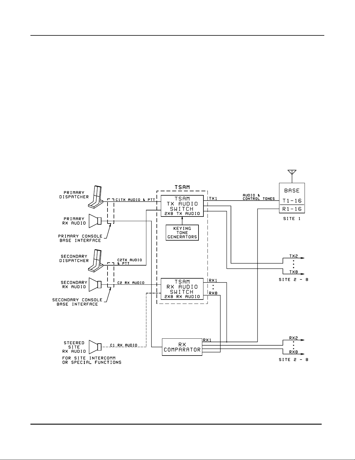
1.5 TSAM Audio Switching
Transmit Audio from the radio control console microphone enters the TSAM through the Console 1
(Main--Steered Channel) and Console 2 (Secondary Channel) audio line inputs. A PTT signal for both
Console 1 and 2 is also connected to the TSAM.
When an operator keys the Main channel, transmit audio from the console is routed through the TSAM to
the steered transmitter line output. The proper keying tones are sent to the steered transmitter, thereby
keying the transmitter and passing console audio. The TSAM routes the console transmit audio to any one
of 8 audio line outputs. Audio is also routed out the expansion bus to other TSAMs, for systems with more
than 8 transmitters.
For Main channel operation, the comparator selects the best receive audio source and routes this audio to
the console Main channel RX audio port.
For TSAM units with Secondary Mode operation, receive audio also connects to the TSAM. The TSAM
routes secondary audio from the selected secondary site to the console secondary channel RX audio port.
Figure 2 TSAM Audio Path Diagram
4
Page 13

TSAM Installation and Maintenance Rev. 2.10 Chapter 2
CTI Products, Inc. Main Channel Operation
2. Main Channel Operation
The Main radio channel is the steered radio channel. The TSAM has inputs to monitor the receiver Vote
or Select lines from the radio system comparator. The Vote indications are processed to determine the start
and end of transmissions from field radios. The TSAM then determines the best site for the next
dispatcher or repeater transmission, based on the criteria outlined in subsequent sections. Upon site
selection, audio from the C1 (Console 1) input line is switched to the steered site line driver.
2.1 Steering Algorithms
Steering algorithms determine how transmitter selection or "steering" occurs. An algorithm processes the
receiver vote information to determine the best transmitter site available. Once determined, the TSAM
activates the steered site. When a site is activated is different from how the site is selected. The Steering
Algorithm determines which site to select, and the Update Mode determines when that site becomes active.
2.1.1 First Receiver Voted Selection Algorithm
One mode for making the steering decision is to select a site based upon the first voted site during a
particular mobile/portable transmission. This mode has the advantage of being able to make a steering
decision before the mobile/portable transmission is complete. However, since the mobile or portable can
change between receive sites during a transmission, the First Received algorithm does not necessarily
reflect the best site to answer the unit at the end its transmission.
2.1.2 Smart-Steer
The Smart-Steer Algorithm watches the voting activity and choses the site that was voted the longest at the
end of the mobile or portable transmission. This gives the benefit of selecting the site closest to the field
unit towards the end of its transmission.
It is not sufficient to make the decision based on the last site voted. On receivers with dual level squelch
circuits, this causes problems. Dual squelch receivers lengthen the squelch tail on weak signals. A
receiver with a slow closing squelch circuit could be voted momentarily at the end of a reception. Picking
the last site voted actually picks a site with poorer reception.
The Smart-Steer selection mode eliminates these problems by picking the site voted for the longest total
time over a programmable period. The TSAM unit offers the benefits of a last-voted steering mode
without the problems caused by slow squelching and dual-level squelch receivers.
Intelligent Selection Algorithm
2.2 Basic Transmit Site Update Modes & Controls
Update Modes
algorithm. Two basic Update Modes are available:
1.
Instant Update Mode
complete.
2.
End of Receive Update Mode
transmission.
determine when the TSAM selects the transmitter based upon the results of the steering
allows the new transmit site to be activated as soon as the steering algorithm is
delays the update till the completion of a portable or mobile
The operation of these update modes can be changed by advanced options such as Home Site Revert and
Dynamic Update Mode.
5
Page 14
TSAM Installation and Maintenance Rev. 2.10 Chapter 2
CTI Products, Inc. Main Channel Operation
2.2.1 Instant Update Mode
Instant Update Mode updates the steered transmitter as soon as the Free-vote timer has expired at the
beginning of a portable/mobile transmission. It is used only with the First Receiver Vote option enabled.
This mode mode is cannot be used with the Smart-Steer™ voting algorithm.
If you have a repeater system and the units will be talking between sites, the Instant update mode has
limitations. In this case, the unit will transmit from the transmitter closest to himself, not necessarily from
the transmitter closest to the person to whom he is talking.
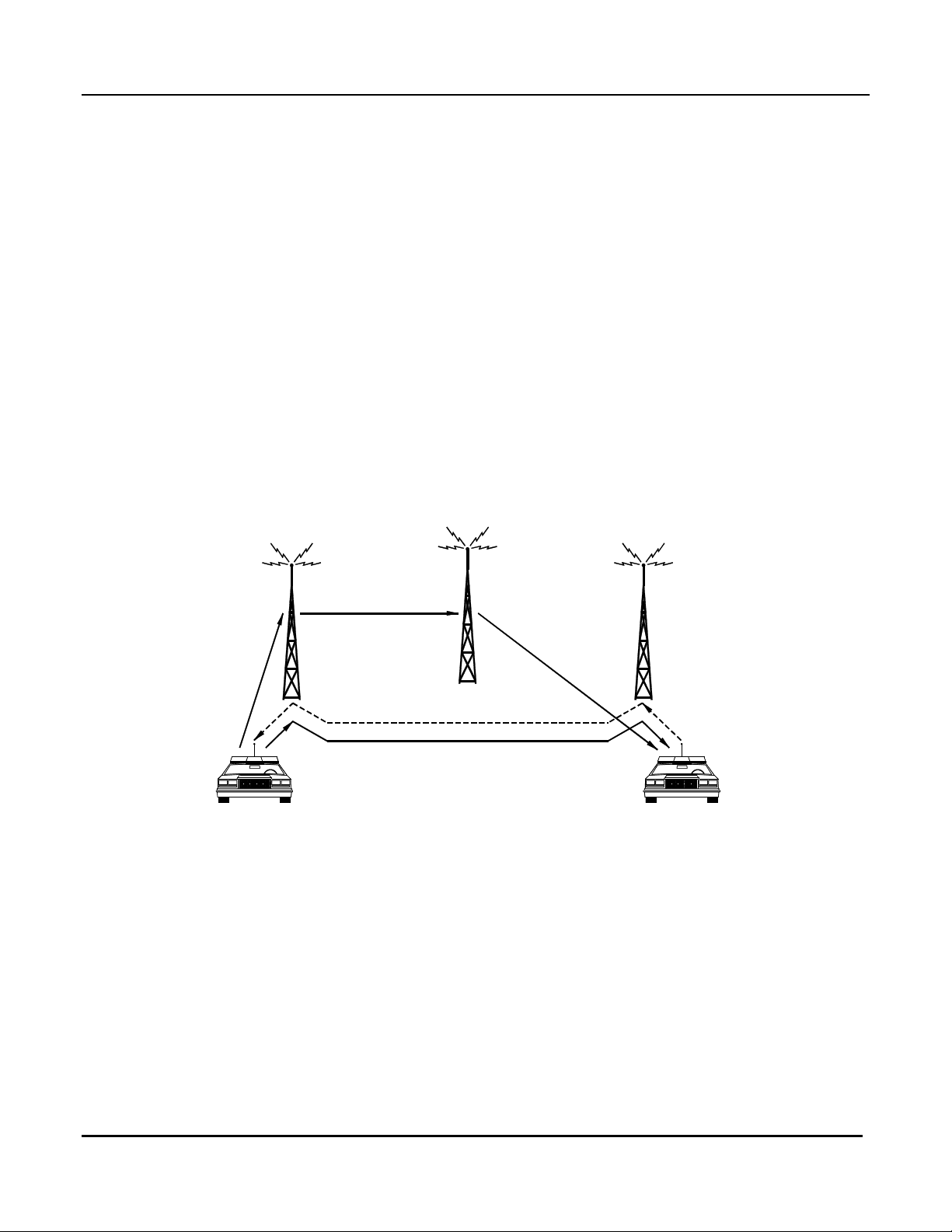
2.2.2 End of Receive (EOR) Update Mode / Ping-Pong Repeater
Operation
As described above, instant update of the steered site may be undesirable for repeater systems. When a
portable/mobile is repeated, it would ideally be transmitted on the site closest to the person to whom he is
talking. The End of Receive Update Mode allows this. In this mode, the TSAM switches to a unit's
closest transmitter at the end of his transmission. Thus, the response to him will come over his transmitter.
This will allow a "ping-pong" selection of transmitters with two mobiles in different areas as shown in
Figure 3.
Home Site
Site A Site B
Car A Car B
Figure 3 Repeater Ping-Pong Operation with End of Receive Mode
In this example, the following happens:
1. Car A transmits and is received on Receiver A.
Car A is repeated over the Home Site (which has the best coverage).
(Home site Revert will be discussed in section 2.3, Initial Transmitter Selection Options.)
When Car A finishes his transmission, the TSAM unit steers to Transmitter A.
Transmission 1
Transmission 2
Transmission 3
CA-80437-100
2. Car B answers through Receiver B and is repeated over Transmitter A.
When Car B finishes his transmission, the TSAM unit steers to Transmitter B.
3. Car A answers. It is received through Receiver A and repeated through Transmitter B.
6
Page 15

TSAM Installation and Maintenance Rev. 2.10 Chapter 2
CTI Products, Inc. Main Channel Operation
Since the Smart-Steer algorithm does not complete vote processing until the end of current receiver
activity, it must use the End of Receive Update Mode.
2.2.3 Instant Update Input
This input can be used to switch between End of Receive Update Mode and Instant Update Mode from the
console. To do this, program the TSAM for End of Receive Update Mode. When the Instant Update
Input is active (low), the TSAM unit will use the First Receiver instant update steering mode on the next
reception. If the TSAM is already programmed for First Receive instant update steering, the input has no
effect.
2.2.4 Fast Steer On Console 1 PTT
TSAM firmware versions 1.60 and later provide a feature that allows the TSAM to steer when Console 1
PTT becomes active, even if receivers are active. This feature is functional only when the steering method
is programmed for Integrated Vote and the Fast Steer option is enabled. This feature allows faster console
transmit operation. The default setting for the Fast Steer option is enabled. It can be programmed in the
TX Steering Menu Integrated Vote section. It is recommended that this option be used whenever the
Smart-Steer™ Integrated Vote algorithm is used.
7
Page 16

TSAM Installation and Maintenance Rev. 2.10 Chapter 2
CTI Products, Inc. Main Channel Operation
2.3 Initial Transmitter Selection Options
If you have made it this far in the manual, you're probably saying, "Okay, I understand how the Instant
Update and End of Receive Update Modes work, but what happens after the system has been quiet for a
while? Which transmitter is used?" (At least I thought I heard you say that.)
The Initial Transmitter Selection Update Options determine which transmitter is selected on an initial
transmission:
1. Home Transmitter
This is usually selected as the central transmitter or the transmitter with the best coverage.
2.
Dynamic Update Mode
Receive/Smart-Steer™ mode. It works well for repeater systems in which the mobiles units will be
talking primarily with units in the same area.
3.
Dynamic Multicast Mode
mode. This is only available with TSAM units that have Secondary capability. It can be used in very
wide-area systems, especially in repeater systems in which the mobiles will be talking with widely
dispersed mobiles. The first transmission (from the console or a mobile) is transmitted over many (or
all) transmitters. Normal steering will be done on subsequent transmissions.
4.
Force Selection:
manually force select a transmitter from the console. See section 4.6, TX Select Console Wiring -Diode Matrix Plug / Schematic for console connections.
selects a customer-programmed Home transmitter after a period of inactivity.
is a combination of Instant Update/First Receive Mode and End of
is a combination of Multicast Mode and End of Receive/Smart-Steer™
Although this is not a programmed mode in the TSAM, the dispatcher can always
2.3.1 Home Transmitter / Transmit Revert Timer
(TSAM Version 1.20 and up)
Using this mode, the first transmission (from a mobile or console) will be made over a customerprogrammed default "Home" transmitter. Subsequent transmissions are steered normally.
After a customer-programmed period of inactivity has passed, the system will again revert to the Home
transmitter. A period of inactivity is any period when there are no Voted signals, Forced Site Selections,
or Console/Repeater PTTs.
The Revert Timer starts to run at the end of the last detected activity. If any new activity occurs, the timer
is reset and held until the activity ceases. When the timer expires, the TSAM then steers the to the HOME
A transmitter. If secondary operation is used and the HOME A transmitter is being used in the secondary
mode, the TSAM reverts to the HOME B transmitter. After the end of activity, the revert timer starts
running again. On the next expiration of the revert timer, the TSAM checks for the availability of the
HOME A transmitter. If HOME A is available, the TSAM the reverts from HOME B to HOME A. If
HOME A is unavailable, the TSAM remains on HOME B. This cycle continues until HOME A becomes
available.
Transmit Revert Timer Programming
The revert timer is accessed through the TSAMs steering options menu. See section 4, Setting
Programmable Options of the TSAM Maintenance and Installation Manual, for information on accessing
the programming menus.
The Revert Timer can be programmed from 5 seconds to 32,767 seconds (9 hours 6 minutes and 7
seconds). Additionally, the timer can be programmed to revert off. With revert off, the TSAM remains on
the last steered site indefinitely. The TSAM is shipped with the revert timer set to 15 seconds. To
program the timer to off, enter any number between 32768 and 65535 into the timer. Any number in this
8
Page 17

TSAM Installation and Maintenance Rev. 2.10 Chapter 2
CTI Products, Inc. Main Channel Operation
range is interpreted as off and will display as revert off on the screen. Numbers outside the range of 5 to
65535 will produce an out of range error, and you will be prompted again to enter a value in the correct
range.
2.3.2 Dynamic Update Mode
(TSAM Version 1.20 and up)
Dynamic update mode is used in conjunction with the EOR (End of Receive Update Mode) and Integrated
Vote mode. Using this mode, the first transmission from a mobile will be made over his transmitter (First
Receive/Instant Update Mode). Subsequent transmissions are steered normally. The first transmission
from a console will be made from either the last transmitter selected or from the Home Transmitter (if it is
programmed and the Revert Timer has timed out).
After a period of inactivity, the dynamic mode timer times out and switches the Update mode to First
receive for the next voted signal. After this, the update mode returns to the Smart-Steer™ Integrated Vote
/ EOR update mode.
Dynamic update allows an EOR update mode system to use a more appropriate steered site when a new
conversation starts. If EOR mode is used alone, a new conversation started on an idle channel would be
transmitted over the last used site. The dynamic update mode selects the site with the best coverage for the
new user. This assumes the new user desires best transmitter coverage in the area near him (as opposed to
across town). After the initial transmit site selection, subsequent sites are steered at the end of
portable/mobile transmissions (EOR update mode).
The Dynamic Mode Timer is programmable from 5 to 32,767 seconds. When programmed for 32,768 to
65,535 seconds the timer is turned off
2.3.3 Dynamic Multicast Mode
Dynamic Multicast Mode is available only on units with the Secondary Mode Option. It is similar to the
Dynamic Mode, but it uses Multicast Mode for the first mobile transmission after the Dynamic Mode
Timer has expired. On subsequent transmissions, the TSAM will use Smart-Steer™ Integrated Vote /
EOR update mode. This allows the first transmission (from the console or a mobile) to be transmitted over
many (or all) transmitters. Normal steering will be done on subsequent transmissions.
2.3.4 Transmitter Revert and Dynamic Mode Timer Resets
The Transmit Revert and Dynamic Mode timers run during periods of inactivity. When a timer is reset, it
is held in the reset state and not allowed to run until the activity has ended. The following types of activity
will reset the timer:
• Vote activity (or internally generated Repeater PTT)
• Console 1 PTT
• Force Select
9
Page 18

TSAM Installation and Maintenance Rev. 2.10 Chapter 2
CTI Products, Inc. Main Channel Operation
2.4 Simplex Operation
In simplex systems, the voting receivers will hear the base station transmitters. If the comparator is active
during this time, the TSAM must be instructed to ignore any voting activity. This is done by programming
the
‘ Sense RX activity during Console 1 PTT’
Steering menu.
The receivers (and comparator Voted output) will still be active for a short time after the console PTT is
released. TSAM units with version 1.62 firmware and later include a
This tells the TSAM unit to ignore any Voted activity for a period after C1PTT is released.
option is set to
‘N’
Simplex PTT Release Mask Timer.
This is found under the TX
The
Simplex PTT Release Mask Timer
option is set to
PTT’
that it a repeater or split-frequency system.
The
‘ Sense RX activity during Console 1 PTT’
are programmed under the TX Steering menu.
. If this option is set to ‘Y’, this timer has no effect, since the TSAM assumes
‘N’
2.5 Repeater Operation
TSAM firmware versions 1.50 and later provide repeater operation for the TSAM unit. In a simplex
system, the TSAM only keys the steered transmitter when a console PTT is activated. In a repeater
system, the TSAM must also key the steered transmitter whenever a received signal is present and repeat
operation is enabled. The TSAM unit will generate its own internal Repeater PTT based upon activity on
the Voted inputs. Repeater transmitters normally remain keyed for a fixed amount of time after the
received signal drops. This time is the Repeater Hang Time.
Hang Time has several purposes, the main purpose is to minimize system access time. When using tone
keying and CTCSS or DCS, various system delays add up. This forces a repeater user to key for a
significant period of time before audio is repeated to receiving stations. By keeping the repeater
transmitter keyed after an initial transmission several of these access delays are eliminated. Hang time also
provides other benefits, such as eliminating some of the squelch bursts on carrier squelch systems and
providing an audible indication that a user accessed the system and keyed the repeater transmitter.
In a repeater system with transmitter steering, access time and hang time are far more complex than in a
single site repeater system. There are some access time tradeoffs to be considered in a steered system.
These are issues that must be addressed in the system design. The TSAM employs several steering
algorithms and is fully programmable which provides maximum flexibility when designing the steering
system.
is only enabled when the
option and the
‘ Sense RX activity during Console 1
Simplex PTT Release Mask Timer
10
Page 19

TSAM Installation and Maintenance Rev. 2.10 Chapter 2
CTI Products, Inc. Main Channel Operation
2.5.1 Repeater Operation with various Steering Algorithms
The steering update mode used determines how repeater keying takes place in the TSAM. The TSAM
uses Instant and End of Receive Update modes. The Smart-Steer algorithm always uses the EOR update
mode. First RX steering uses either Instant update or EOR update modes. Repeater keying in each of
these modes is described in the following sections.
2.5.1.1 Repeater Keying with Instant Update Mode
For repeater mode operation, the TSAM will key the steered transmitter when the Free Vote time period
expires. The Free Vote time starts running the instant vote activity is detected on the TSAM inputs.
If the TSAM is in instant update mode, the proper site is steered just before the keying starts. Console 1
TX audio is then routed to the steered site. Repeat audio from the comparator must be routed to the C1
TX audio port. This is accomplished by taking the repeat audio output of a comparator with console
priority capability, or by means of an external relay which will switch between repeat and console audio.
One disadvantage of instant update keying is that the repeater transmitter is not keyed until after the Free
Vote timer expires. If Free Vote is set to a high value, to give the comparator time to make a better voting
decision, the initial part of a transmission will not be repeated. Care must be taken when setting Free Vote
to balance steering performance with system access time. Only repeat audio is effected by Free Vote.
Console audio is not cut off by Free Vote.
2.5.1.2 Repeater Keying with EOR Update Mode
In this mode, new vote activity is repeated over the last used transmitter site (a new site is not immediately
steered). Repeater keying is initiated at the time Free Vote expires. With EOR Update mode, Free Vote
can be set very short or to 0 msec with no degradation of steering performance. This is because the
steering decision is made at the end of vote activity (not at the beginning). After EOR, a steering decision
is made and the new TX site is steered. The next voted signal is then repeated on this site.
2.5.2 Repeater Hang Time
Repeater Hang Time is used on conventional repeater systems to improve system access time. During
hang time, the repeater transmitter remains keyed. Subsequent transmissions due not incur the delays
encountered when re-keying the repeater transmitter. These delays consist of 160ms typical tone keying
delay, and 200ms typical PL decode delay for the receiving field radio.
In a transmitter steering system, the repeater transmitter may change sites on each retransmission, requiring
that a new transmitter be keyed each time. This makes it more difficult to provide the same quick access
of a single transmitter repeater system.
To minimize system access the TSAM uses the following system hang time algorithm.
2.5.2.1 Repeater Hang Time with Instant Update Mode
In Instant Update Mode, when repeat traffic ends, the TSAM keeps the current system transmitter keyed.
When the next transmission begins, the TSAM steers to the site for that transmission. If no site change
occurred, the transmission can proceed over the current transmitter that is still keyed due to system hang
time. In this case, system access time is reduced. If a site change is required to repeat the next
transmission, then the TSAM unkeys the current site and keys the new site. In this case, additional system
access time is added for a new site key-up and PL decoding in the field radio.
11
Page 20

TSAM Installation and Maintenance Rev. 2.10 Chapter 2
CTI Products, Inc. Main Channel Operation
2.5.2.2 Repeater Hang Time with EOR Update Mode
For EOR updated modes, the TSAM steers to the proper site for the next transmission when the current
transmission ends. If no site change occurs, the current site remains keyed for the duration of hang time.
If a site change does occur, the current site is unkeyed and the new site is keyed. It remains keyed for the
duration of hang time. When subsequent vote activity starts a repeater transmission, the proper site will
be already keyed. This improves system access time.
2.5.3 RPT Disable Input
When activated, the RPT DISABLE input knocks down any ongoing repeater transmission (including hang
time) and prevents any further repeater transmissions from taking place. When inactive, any vote activity
generates a repeater transmission and keys the steered site. If RPT DISABLE goes inactive after vote
activity ends but during the normal hang time period, hang time is not generated. If RPT DISABLE is
activated during hang time and deactivated before hang time expires, no further hang time is generated.
2.5.4 RPT KEY Output
The TSAM generates a RPT KEY signal for use in systems where transmitter keying is done with external
hardware. In these systems, the RPT KEY signal can be used as the PTT signal for the external transmitter
keying hardware. The TSAM generates this signal so that it has control of the hang time keying
generation.
2.5.5 Repeater Keying Programming Options
Enable Repeater Operation
When this option is enabled, the TSAM generates keying tones whenever vote activity is detected. The
TSAM also generates repeater hang time. If keying tones are disabled, then only the RPT KEY output
becomes active when repeater operation is enabled. Secondary channel operation is not supported with
Repeater Operation enabled.
Enable TSAM Internal Tone Keying
When internal keying tones are disabled, tones are not generated for any Main channel function.
Secondary channel functions still generate all required secondary channel control tones.
Repeater Hang Time
Repeater hang time can be programmed for 0 to 32767 milliseconds, and is normally set so the repeater
transmitter is not dropped during a conversation. For more detail on the operation of Repeater Hang Time,
see section 2.5.2 on page 11.
Resteer Key-up Delay Time
Resteer Key-up Delay forces a delay time between unkeying a base station and then resteering and keying
a new base station. It is programmable from 0-2000 milliseconds. The key-up delay is set long enough so
that the first base completes its unkey sequence. Typically, this delay is as long as 200 milliseconds. This
allows for LLGT detect time and the time for PL reverse burst to be transmitted from the base being
unkeyed. This time can be set to zero if key-up of the second transmitter takes around 200 milliseconds or
if the interference from having two transmitters keyed simultaneously is not objectionable.
12
Page 21
TSAM Installation and Maintenance Rev. 2.10 Chapter 2
CTI Products, Inc. Main Channel Operation
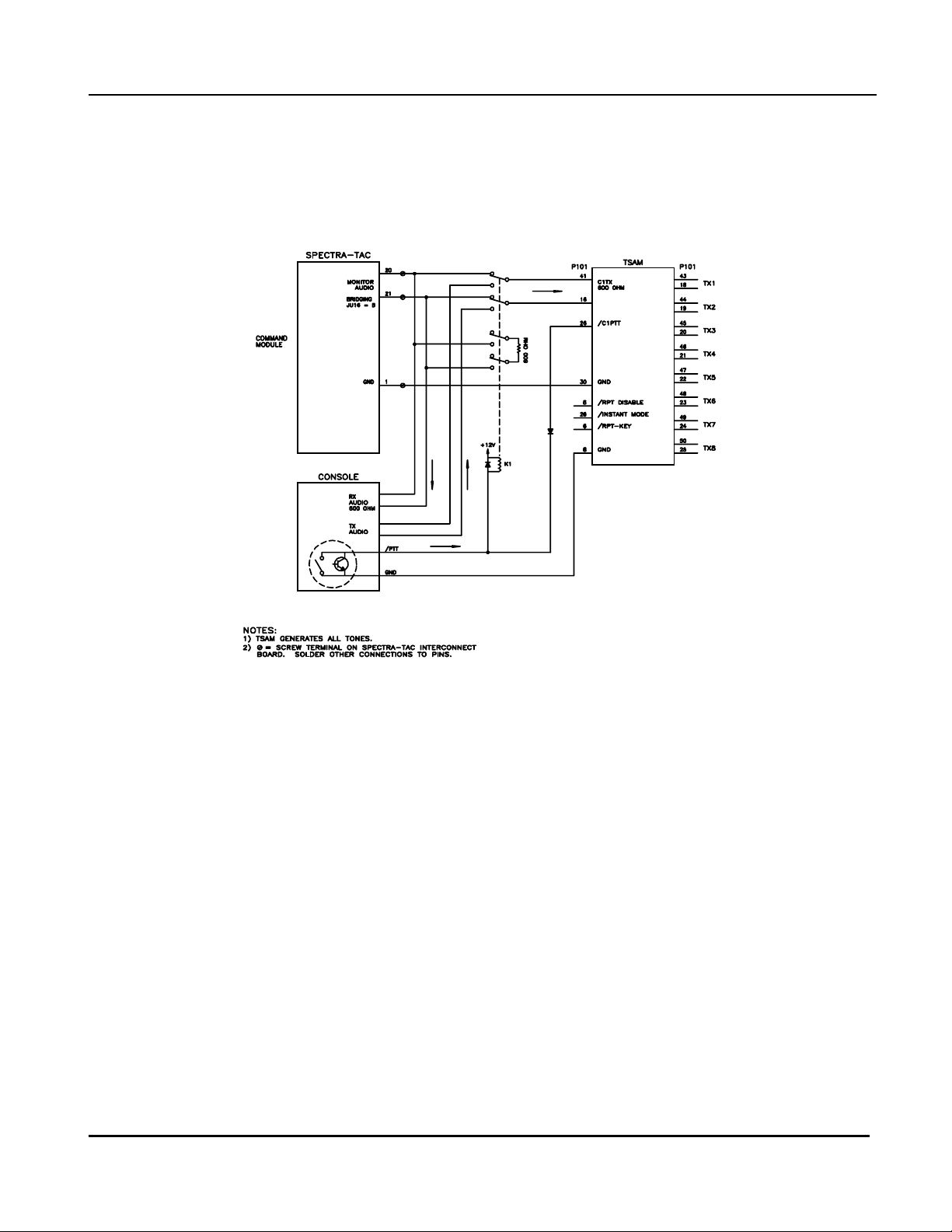
2.5.6 Console Priority with Repeater Systems
In a typical transmitter steering repeater system, a transmitter is keyed from two different sources.
Detection of a received signal will key a transmitter so it can be "repeated", and the systems dispatcher will
key the transmitter from the dispatch console. In many systems, it is required for the dispatcher to have
priority access to the steered transmitter.
Figure 4 TSAM Console Priority Connections
To provide console priority, an external audio switching relay is added as shown in Figure 4. The console
PTT line is connected to the C1PTT input of the TSAM. Note there is no PTT connection from the
receiver comparator. This is because the TSAM monitors the comparators vote indicate lines and
generates an internal repeater PTT when vote activity is detected.
Since priority is given to console PTT, the TSAMs keying is different when a console keys than when a
repeater PTT keys. These differences are as follows:
• There is no hang time generated when the console unkeys.
• Force Site selects cannot be made while the console is keyed.
• Resteering during console PTT in normally disabled.
If a Force Site Select is activated during a repeater PTT, the current transmitter is immediately unkeyed
and the forced transmitter is keyed. Depending on the timing requirements of the system base stations, a
small portion of a transmission is lost while a station is unkeyed and a new station keyed. If a Force Site
Select is activated during console PTT, it is ignored.
Since resteering during console PTT is normally disabled, any receive activity that occurs while the
console is transmitting will not effect transmitter steering. With resteering enabled during console PTT,
receive activity that steers to a new site is remembered and the new site is updated when console PTT is
released.
Application Notes are available to describe Console Priority with a number of other comparators.
13
Page 22

TSAM Installation and Maintenance Rev. 2.10 Chapter 2
CTI Products, Inc. Main Channel Operation
2.6 Multicast Options
Unit Versions 1.70 and up / Units with Secondary System Capability Only
The Multicast feature allows the dispatcher to key a number of transmitters simultaneously on the main
channel for system-wide announcements. When the latched Multicast input is active and the console is
keyed, the Transmitter Steering System keys all transmitters that are programmed for Multicast operation.
If a transmitter (if any) is in Secondary mode, it will not be used in Multicast mode..
When the Multicast input goes inactive, the TSAM will return to the normal steered operation on the main
channel.
Caution:
The Multicast option is not intended to serve as a Simulcast controller.
There is no simulcast gain, phase, or delay optimization in the TSAM unit.
If the installed system does not have simulcast transmitters and appropriate
simulcast optimized control lines with controlled amplitude, delay and
phase, the system will experience (possibly severe) distortion in RF
coverage overlap areas.
The customer shall accept any and all responsibility and risks associated
with the operation of the system in multicast mode.
Depending upon your system coverage, you may want all or just some of the transmitters to be enabled for
Multicast Mode.
Example 1:
probably want to enable all transmitters for Multicast.
Example 2:
cover well enough for an initial call-up without causing too much distortion in the overlap area.
The transmitters are enabled through the Multicast menu.
If you have a very large system area with minimal overlap between transmitters, you would
If you have 8 relatively closely spaced transmitters, you may find that 3 or 4 of these will
2.6.1 Multicast Operation and Secondary Transmitters
If a transmitter is selected for Secondary operation and the Multicast input becomes active, that transmitter
will not be eligible for Multicast operation while it is selected as a Secondary Transmitter. When that
transmitter becomes de-selected, it will when then be used in Multicast operation on the next transmission
if it was enabled in the Multicast Menu.
If Multicast Mode is turned on and the operator tries to select one of the Multicast transmitters for
Secondary operation, he will hear a warning tone on the Secondary channel.
2.6.2 Dynamic Mode with Multicast Operation
Multicast Mode can be used on the first transmission in a conversation under Dynamic Mode. This
replaces the "First Receive" Dynamic Mode option. See the programming under Transmitter Steering /
Dynamic Mode section.
14
Page 23
TSAM Installation and Maintenance Rev. 2.10 Chapter 3
CTI Products, Inc. Secondary Channel Operation
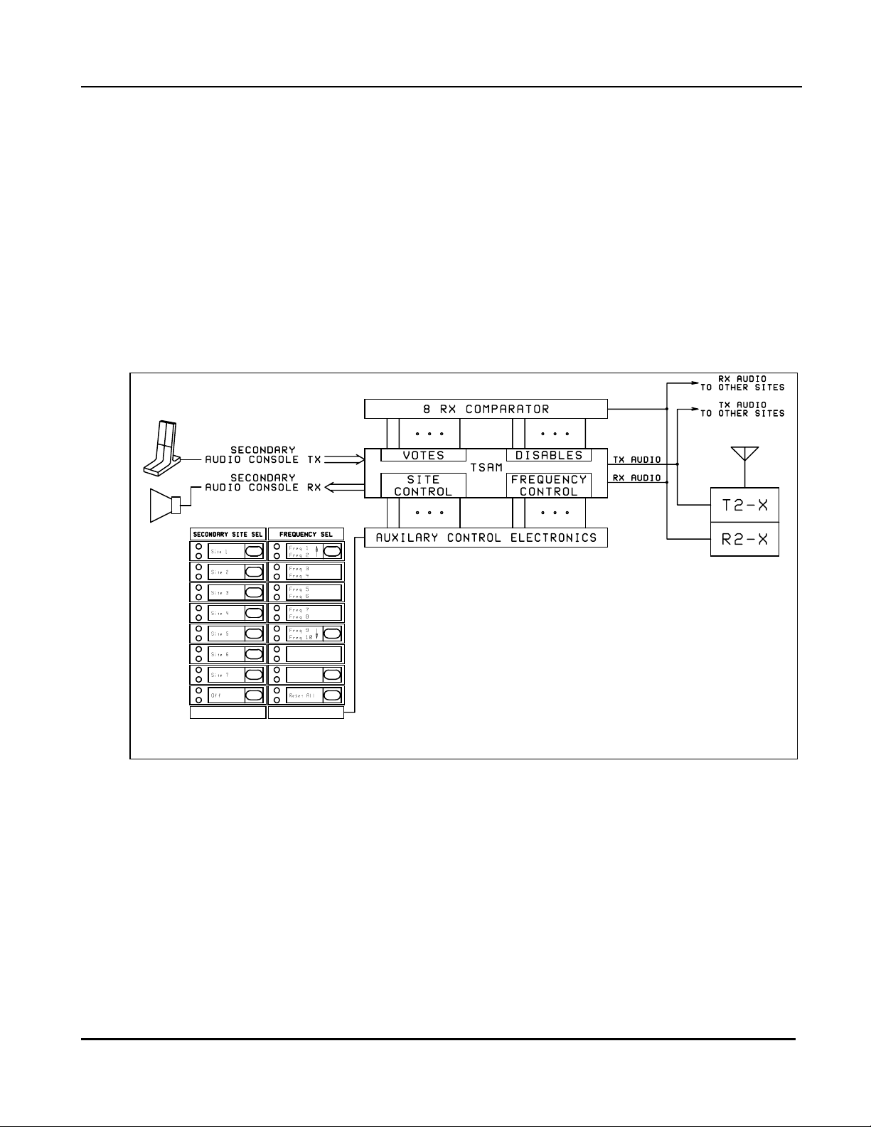
3. Secondary Channel Operation
Only available on TSAM units with Secondary Option
One unique feature of the TSAM is that it allows a properly equipped steered base station
(receiver/transmitter pair) to be removed from the transmitter steering system and operate as an
independent base/repeater on a second channel. The secondary TSAM channel looks like and additional
channel to the system console. The TSAM supports the selection of up to 15 frequencies for the secondary
base.
Secondary Mode is useful for allowing a wide area coverage system to be used to handle a local incident
without tying up the main channel over the whole coverage area.
Figure 5 Typical secondary channel control
15
Page 24

TSAM Installation and Maintenance Rev. 2.10 Chapter 3
CTI Products, Inc. Secondary Channel Operation
3.1 Secondary Site Selection
The TSAM automatically completes the following steps when a dispatcher selects a secondary site.
Secondary Operation is initiated when the TSAM detects a non-zero secondary site on the binary active
low Site Select inputs. If the site is currently voted, the receiver is immediately disabled, forcing the
receive comparator to re-vote. If the site is currently keyed or steered, the transmitter is disabled and the
TSAM steers to the HOME A or the HOME B site. (If the HOME A site was selected for secondary
operation the TSAM steers to HOME B). Any interlocking required to prevent the TSAM from disabling
active sites is done externally.
The Secondary Site Select Sequence
1. TSAM C2 RX audio is normally muted and remains so. This prevents the secondary dispatcher from
hearing F1 comparator status tone.
2. The TSAM disables the secondary base RX at the receive comparator by forcing its Disable line low
and marking the transmitter as being unavailable for transmitter steering in internal memory.
3. The TSAM sends the currently selected secondary frequency select tones. The secondary frequency is
determined by 4 binary Secondary Frequency Inputs (SF1-SF8). These control lines are set by
dispatcher using the console Frequency Select control. The TSAM uses a programmable debounce
time to allow the inputs to settle before reading the final frequency value. The debounce time allows
the operator to scroll the frequency list without sending frequency select control tones for every
frequency. This time is programmable in 1 ms increments from 0 to 65.535 seconds (due to the 20 ms
scanning latency, the exact debounce is ± 20 ms).
4. If C2 PTT is detected before the debounce time expires, the transmitter is keyed immediately using the
most current frequency select input values. To allow for adequate debounce of the secondary site
select inputs, the inputs are scanned 20ms after the detection of C2 PTT.
5. Secondary Base RX audio outputs and TX audio inputs are routed to the secondary channel control
card in the dispatch console, and the audio paths are unmuted.
6. TSAM monitors Secondary PTT to initiate a secondary transmission.
7. Operator is free to use the Secondary channel or to change the frequency if required.
8. If interlocking of secondary site or frequency control is required, it must be done in the console.
16
Page 25

TSAM Installation and Maintenance Rev. 2.10 Chapter 3
CTI Products, Inc. Secondary Channel Operation
3.2 Secondary Site Select "Off"
1. This function terminates secondary operation and returns the secondary base to the Main steered
channel.
2. Secondary Operation is terminated when all secondary select inputs return high (active low
inputs).
3. The TSAM mutes C2 RX Audio.
4. The TSAM sends the F1 frequency change tone sequence to the secondary base.
5. The TSAM re-enables the receiver by releasing the Disable line to the receive comparator. The
TSAM marks the reverted transmitter as being available for transmitter steering in internal
memory.
3.3 Alert Tone Generation
If an attempt is made to transmit on the secondary channel when no secondary site is selected, a warning
tone is sent to the console. The warning tone is generated by the secondary keying tone generator and
routed through the cross-point audio switch to the secondary console RX audio line driver circuit.
3.4 Secondary Channel PL Monitor Control
Unit Versions 1.70 and up / Secondary System Only
The TSAM can control PL Monitor on the Secondary system. One of two modes may be selected,
Momentary Mode or Sustained Mode.
Momentary PL Monitor is used to check for activity on a Secondary channel before transmitting. It
functions much like a PL monitor on a typical remote control unit. The operator presses a momentary PL
Monitor button, and the base station remains in monitor mode until the next transmission.
Sustained PL Monitor is used to operate a Secondary station in a pseudo carrier squelch mode. This
allows the operator to hear traffic from mobile units that do not transmit the proper PL tones. It requires a
latched console output. The TSAM will generate a PL Monitor tone sequence after each transmission as
long as the PL Monitor input is active.
The PL Monitor function is sent out as two tones:
HLGT + PL Monitor Tone.
Some stations will not decode a new tone command immediately after a transmission or another tone
command. The PL Monitor Delay time is a dead time that allows the station tone decoder to reset before
the PL Monitor tone is sent.
When an operator de-selects a secondary station, the TSAM sends the F1 keying tone or F1 Revert tone to
the station. The station should go back into normal (guarded) PL mode when it changes back to F1.
Program the PL Monitor Control parameters from the Secondary menu:
PL Monitor Tone Timing is shown in sections 7.2 and 7.3.
17
Page 26

TSAM Installation and Maintenance Rev. 2.10 Chapter 3
CTI Products, Inc. Secondary Channel Operation
3.4.1 Momentary PL Monitor Control
When the Monitor input is momentarily activated, the TSAM sends a PL Monitor tone out the selected
Secondary site. The station re-enables the PL decoder on the next transmission.
3.4.2 Sustained PL Monitor Control
When the Monitor input is activated, the TSAM sends a PL Monitor tone out the selected Secondary site.
Since the station re-enables the PL decoder after a transmission, the TSAM will re-send the PL Monitor
tone after each transmission, as long as the PL Monitor input is active.
When the PL Monitor input goes inactive and a Secondary Site is still selected, the TSAM will generate
the appropriate Secondary Frequency tone sequence to that site.
If the PL Monitor input is active when a Secondary Site is first selected, the TSAM unit will do the
following:
1. Send the Secondary Frequency tone sequence
2. Wait for the PL Monitor Delay time
3. Send the PL Monitor tone sequence.
After the dispatcher releases the PTT, there will be a slight delay in receiving a mobile without the proper
PL, due to the time required to send and decode the PL Monitor tone sequence.
18
Page 27

TSAM Installation and Maintenance Rev. 2.10 Chapter 4 CTI Products, Inc. Installation
4. Installation
Installation of the TSAM consists of:
• Pre-setting jumper options
• Mounting the unit in a cabinet
• Routing the 25 pair control and audio cable(s) to the cross-connect panel
• Routing the power cable
• Programming the options
• Setting the system transmit and receive audio levels.
4.1 Power Supply Requirements
The TSAM requires either 24V DC or 20V AC at 1 amp maximum for proper operation. A 2-conductor
power connector and cord are supplied. Although the TSAM is polarity insensitive, observe proper color
coding conventions when connecting the TSAM to a DC supply.
4.2 Expansion TSAMs for more than 8 Transmitters
Multiple TSAMs can be linked together to control more than 8 transmitters or receivers on one channel.
As many as 8 TSAMs can be tied together. This allows control of up to 64 transmitters. If you have
expansion units, you will have to change some jumpers in the units before you mount them (unless the
units are marked as expansion units from the factory).
4.2.1 Expansion Cables
When multiple TSAMs are used together, they are linked through the expansion bus. The expansion bus is
made up of the necessary audio and control busses to allow TSAMs to share transmitter control hardware.
The master and slave units are connected via a daisy-chain ribbon cable that connects to P103 on all
TSAMs on the channel. Cables are available for systems with 2-8 TSAM units. See Table 1 TSAM
Accessories for part numbers.
When installing the expansion cables, install the supplied cable grounding clamps.
19
Page 28

TSAM Installation and Maintenance Rev. 2.10 Chapter 4
CTI Products, Inc. Installation
4.2.2 Expansion TSAM Addressing & Jumpers
Address switch SW102 on the front of the TSAM is used to set TSAM SPI bus addresses.
A Master TSAM always has address 0. Additionally, the Master TSAM drives the Main and Secondary
channel expansion transmit audio busses and receives audio on the Main and Secondary channel receive
audio expansion busses.
Slave TSAM units have addresses 1-7. The addresses must be sequential and no addresses may be
skipped.
The SW102 master/slave switch must be in the S position on all Slave TSAMs.
The Master TSAM controls the transmitter steering system. The MCU and control logic on the slave
TSAM operates only in a standby diagnostic mode. All of the Slaves I/O logic and audio switching are
controlled by the master TSAM MCU.
TSAM
Address
0 0,0,0 M
1 0,0,1 S
2 0,1,0 S
3 0,1,1 S
4 1,0,0 S
5 1,0,1 S
6 1,1,0 S
7 1,1,1 S
SW102
4,2,1
SW102
M/S
(Master
)
(Slave)
(Slave)
(Slave)
(Slave)
(Slave)
(Slave)
(Slave)
TX
Sites
1-8 E109-E112,E125 = In
9-16 E109-E112,E125 = See Note
17-24 E109-E112,E125 = See Note
25-32 E109-E112,E125 = See Note
33-40 E109-E112,E125 = See Note
41-48 E109-E112,E125 = See Note
49-56 E109-E112,E125 = See Note
57-64 E109-E112,E125 = In
Jumpers
E123,E127,E124,E128 = A
E217,E218,E219,E220 = Top
E123,E127,E124,E128 = B
E217,E218,E219,E220 = Bottom
E123,E127,E124,E128 = B
E217,E218,E219,E220 = Bottom
E123,E127,E124,E128 = B
E217,E218,E219,E220 = Bottom
E123,E127,E124,E128 = B
E217,E218,E219,E220 = Bottom
E123,E127,E124,E128 = B
E217,E218,E219,E220 = Bottom
E123,E127,E124,E128 = B
E217,E218,E219,E220 = Bottom
E123,E127,E124,E128 = B
E217,E218,E219,E220 = Bottom
Table 2 Expansion TSAM Switch and Jumper Settings
0 = down, 1= up
Note: RS-485 Terminators
Jumpers E109-E112, and E125 install RS-485 terminator resistors on the expansion bus. The terminators
are always required on the first and last TSAMs in a system. This means the Master TSAM and the last
Slave TSAM always have these jumpers installed. All other Slave TSAMs have these jumpers removed.
20
Page 29
TSAM Installation and Maintenance Rev. 2.10 Chapter 4
CTI Products, Inc. Installation
4.2.3 Expansion Unit Programming
When a system is programmed for a slave (expansion) TSAM and the slave unit is disconnected, the
system must be reprogrammed to insure proper operation. If you must run a system with an expansion unit
disconnected, re-program the master TSAM for one less expansion unit. Be sure that the expansion units
are addressed sequentially.
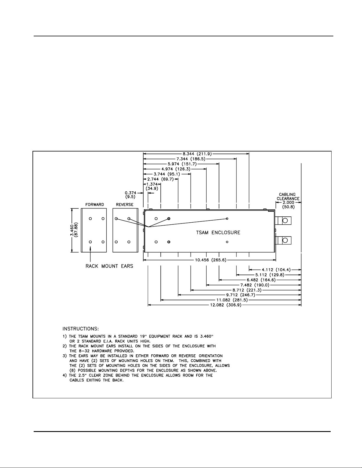
4.3 Physical installation of TSAM
A set of rack mount ears are furnished with the TSAM. There are two mounting locations on the TSAM
enclosure for the mounting ears. There are two sets of mounting holes in the ears. The ears may be
mounted with the mounting flange forward or reversed. These options allow the TSAM to be mounted in
any of 8 positions. This allows mounting in a variety of racks or cabinets.
Figure 6 TSAM Mounting Positions
21
Page 30

TSAM Installation and Maintenance Rev. 2.10 Chapter 4
CTI Products, Inc. Installation
4.4 P101 (TX) Cable Signals
This male connector is present on all units. The TX cable contains all of the transmit audio line outputs
and control signals.
Pins In/Out Name Notes
26 In Console 1 M Keying (/PTT) LOW=PTT
1 In Console 1 Coded/Clear LOW=Coded
27 In Console 2 M Keying (/PTT) LOW=PTT
2 In Console 2 Coded/Clear LOW=Coded
28 In FORCESEL LOW=Force Select Site
3In
29 In
4Out
30 Ground
5 Out Console 1 PTT Out COM Relay Closure=PTT
31 Out Console 1 PTT Out N.O. Relay Closure=PTT
6 Ground
32 In RX Voted 1 LOW=Voted
7 In RX Voted 2 LOW=Voted
33 In RX Voted 3 LOW=Voted
8 In RX Voted 4 LOW=Voted
34 In RX Voted 5 LOW=Voted
9 In RX Voted 6 LOW=Voted
35 In RX Voted 7 LOW=Voted
10 In RX Voted 8 LOW=Voted
36 Ground
11 In/Out TX Sel 1 /TXS1
37 In/Out TX Sel 2 /TXS2 LOW=Steered or Forced
12 In/Out TX Sel 3 /TXS3 LOW=Steered or Forced
38 In/Out TX Sel 4 /TXS4 LOW=Steered or Forced
13 In/Out TX Sel 5 /TXS5 LOW=Steered or Forced
39 In/Out TX Sel 6 /TXS6 LOW=Steered or Forced
14 In/Out TX Sel 7 /TXS7 LOW=Steered or Forced
40 In/Out TX Sel 8 /TXS8 LOW=Steered or Forced
15 Ground
41 In Console 1 TX Audio Tip
16 In Console 1 TX Audio Ring "
42 In Console 2 TX Audio Tip
17 In Console 2 TX Audio Ring "
43 Out TX 1 Audio Tip 600 Balanced Output
18 Out TX 1 Audio Ring "
44 Out TX 2 Audio Tip 600 Balanced Output
19 Out TX 2 Audio Ring "
45 Out TX 3 Audio Tip 600 Balanced Output
20 Out TX 3 Audio Ring "
46 Out TX 4 Audio Tip 600 Balanced Output
21 Out TX 4 Audio Ring "
47 Out TX 5 Audio Tip 600 Balanced Output
22 Out TX 5 Audio Ring "
48 Out TX 6 Audio Tip 600 Balanced Output
23 Out TX 6 Audio Ring "
49 Out TX 7 Audio Tip 600 Balanced Output
24 Out TX 7 Audio Ring "
50 Out TX 8 Audio Tip 600 Balanced Output
25 Out TX 8 Audio Ring "
RPT DISABLE LOW=Repeater TX Disabled
Instant Mode LOW=force Instant Update
Steering
RPT KEY LOW=Repeater PTT for
external transmitter
hardware
LOW=Steered or Forced
Force In/Selected Out
600 or 10KΩ balanced Input
600 or 10KΩ balanced Input
Table 3 P101-TX Cable Connector Pinout and I/O Functions
22
Page 31

TSAM Installation and Maintenance Rev. 2.10 Chapter 4
CTI Products, Inc. Installation
4.4.1 P101 Main Channel Signal Definitions
Console 1 M Keying (/PTT) (C1PTT) Logic signal from Console
Low = PTT on Main Channel
Console 1 Coded/Clear Logic signal from Console
Low = Coded TX Main Channel
High = Clear TX Main Channel
Console 1 TX Audio Tip & Ring 600 Ohm (Or Bridging) TX Audio from Console (Main
Channel)
RX Voted 1-8 Logic signals from comparator
Low = Voted
Instant Mode Logic signal from Console
Low = Instant TX Update Mode
RPT DISABLE Logic signal from Console
Low = Disable Repeater Operation
High = Enable Repeater Operation
(if programmed)
RPT KEY Logic Output from TSAM (Not normally used)
Low = PTT during Repeat operation
Console 1 PTT Out COM & N.O Relay contacts active when C1PTT is active.
FORCESEL Logic signal from Console (used with /TXS1-8)
Low to Force Select.
This tells the TSAM to use the /TXS1-8 lines as inputs.
Holding this line low also disables automatic steering.
TX Sel 1-8 /TXS1-8 Bi-directional logic signals
To/from Console (Main Channel)
Outputs from TSAM (when FORCESEL is High):
Low = Selected TX
Inputs to TSAM (Read on low-going FORCESEL):
Low = TX to force select
TX 1 - 8 Audio Tip & Ring 600 Ohm TX Audio Outputs to Transmitters
(Main Channel)
Gnd Negative Ground (common for all logic signals)
4.4.2 P101 Secondary Channel Signal Definitions
Console 2 M Keying (/PTT) (C2PTT) Logic signal from Console
Low = PTT on Secondary channel
Console 2 Coded/Clear Logic signal from Console
Low = Coded TX Secondary Channel
High = Clear TX Secondary Channel
Console 2 TX Audio Tip & Ring 600 Ohm (Or Bridging) TX Audio from Console (Secondary
Channel)
Gnd Negative Ground (common for all logic signals)
23
Page 32

TSAM Installation and Maintenance Rev. 2.10 Chapter 4
CTI Products, Inc. Installation
4.5 P201 (RX) Cable signals
This male connector is present only on units with Secondary Mode. It contains all receive audio line
inputs, control inputs for secondary operation, and a few other functions.
Pins In/Out Function Notes
26 Out Disable RX 1 LOW=Disable Site Receiver
1 Out Disable RX 2 LOW=Disable Site Receiver
27 Out Disable RX 3 LOW=Disable Site Receiver
2 Out Disable RX 4 LOW=Disable Site Receiver
28 Out Disable RX 5 LOW=Disable Site Receiver
3 Out Disable RX 6 LOW=Disable Site Receiver
29 Out Disable RX 7 LOW=Disable Site Receiver
4 Out Disable RX 8 LOW=Disable Site Receiver
30 Ground
5 Out Console 2 PTT Out COM Relay Closure=PTT
31 Out Console 2 PTT Out N.O. Relay Closure=PTT
6 Ground
32 In Sec Site Sel 1 /SS1 Active Low Binary Site Data
7 In Sec Site Sel 2 /SS2 "
33 In Sec Site Sel 4 /SS4 "
8 In Sec Site Sel 8 /SS8 "
34 In Sec Site Sel 16 /SS16 "
9 In Sec Site Sel 32 /SS32 "
35 In Multicast Enable (Main Channel) LOW = Enable Multicast (if pgm)
10 In PL Monitor Secondary Channel LOW = PL Monitor
36 Ground
11 In Sec Freq Sel 1 /SF1 Active Low Binary Freq Data
37 In Sec Freq Sel 2 /SF2 "
12 In Sec Freq Sel 4 /SF4 "
38 In Sec Freq Sel 8 /SF8 "
13 In Reset All Low=Reset Main Bases to F1
39 In Spare R3
14 In Spare R4
40 In Spare R5
15 Ground
41 Out Console 1 RX Audio Tip 600 Balanced Output
16 Out Console 1 RX Audio Ring "
42 Out Console 2 RX Audio Tip 600 Balanced Output
17 Out Console 2 RX Audio Ring "
43 In RX 1 Audio Tip
18 In RX 1 Audio Ring "
44 In RX 2 Audio Tip
19 In RX 2 Audio Ring "
45 In RX 3 Audio Tip
20 In RX 3 Audio Ring "
46 In RX 4 Audio Tip
21 In RX 4 Audio Ring "
47 In RX 5 Audio Tip
22 In RX 5 Audio Ring "
48 In RX 6 Audio Tip
23 In RX 6 Audio Ring "
49 In RX 7 Audio Tip
24 In RX 7 Audio Ring "
50 In RX 8 Audio Tip
25 In RX 8 Audio Ring "
600 or 10KΩ balanced Input
600 or 10KΩ balanced Input
600 or 10KΩ balanced Input
600 or 10KΩ balanced Input
600 or 10KΩ balanced Input
600 or 10KΩ balanced Input
600 or 10KΩ balanced Input
600 or 10KΩ balanced Input
Table 4 P201-RX Cable Connector Pinout and I/O Functions
24
Page 33

TSAM Installation and Maintenance Rev. 2.10 Chapter 4
CTI Products, Inc. Installation
4.5.1 P201 Secondary Channel Signal Definitions
Console 2 M Keying (/PTT) (C2PTT) Logic signal from Console
Low = PTT on Secondary channel
Disable RX 1 - 8 Logic Output to Comparator
Low to disable receiver slot
during Secondary operation
Console 2 PTT Out COM & N.O Relay contacts active when C2PTT is active.
Sec Site Sel 1 - 32 (/SS1 - /SS32) Logic signals from Console
Active Low Binary Secondary Site Select Lines
All High = No Secondary Site Selected
/SS1 Low = Secondary Site 1
/SS2 Low = Secondary Site 2
/SS1 and /SS2 Low = Secondary Site 3
etc.
Sec Freq Sel 1 -8 ( /SF1- /SF8) Logic signals from Console
Active Low Binary Secondary Frequency Select
All High = Secondary F1 (Base station F2)
/SF1 Low = Secondary F2 (Base Station F3)
etc. See Secondary Site Select Table for more details.
Reset All Logic signal from Console
Low sends out a "Revert to F1" tone sequence
to all TX sites
Spare R3 - R5 Unused
Console 2 RX Audio Tip & Ring 600 Ohm Audio Output to Console
RX Audio for selected Secondary Channel
RX 1 - 8 Audio Tip & Ring 600 Ohm (Or Bridging) Audio from Receivers
This is typically in bridging mode and is connected
in parallel with the Comparator RX wireline inputs.
PL Monitor Logic signal from Console
Low = PL Monitor. See section 3.4, Secondary Channel PL
Monitor Control for operation
Gnd Negative Ground (common for all logic signals)
4.5.2 P201 Main Channel Signal Definitions
Console 1 RX Audio Tip & Ring 600 Ohm Audio Output
Selected RX Audio for Main Channel
This is not used in actual operation, since the comparator
selects the best signal, but the TSAM routes the RX audio
from the selected base station to this pair.
Multicast Logic signal from Console
Low enables Multicast Mode (if programmed)
Gnd Negative Ground (common for all logic signals)
25
Page 34

TSAM Installation and Maintenance Rev. 2.10 Chapter 4
CTI Products, Inc. Installation
4.6 TX Select Console Wiring -- Diode Matrix Plug / Schematic
The Diode Matrix Plug is available as an accessory to the TSAM. It can be used to interface consoles with
simple Inputs & Outputs with the bi-directionsl TSAM TX Select lines.
TX
SELECT
INDICATORS
1
2
3
4
5
6
7
8
TX
SELECT
SWITCHES
1
2
3
CROSS
CONNECT
WIRING
DIODE
PUNCH
BLOCK
26 1
34 9
27
35 10
28
36
11
CONNECT
2
3
CROSS
WIRING
TSAM
PUNCH
BLOCK
11
TXS1
37
TXS2
12
TXS3
38
TXS4
13
TXS5
39
TXS6
14
TXS7
40
TXS8
28 FORCE SEL
15 GROUND
4
5
6
7
8
29
37
30
38
31
39
32
40
33
41
4
12
5
13
6
14
7
15
8
16
CROSS
CONNECT
WIRING
CA-80401-100
Figure 7 TX Select Console Wiring -- Diode Matrix Plug Schematic
The TXS1-8 lines are bi-directional. Normally they provide an output to indicate the selected transmitter.
When the Force Sel line is brought low, the TSAM reads the TXS lines as inputs and force-steers to the
site selected by the console.
26
Page 35

TSAM Installation and Maintenance Rev. 2.10 Chapter 4
CTI Products, Inc. Installation
4.7 TX Select Console Wiring with Diode Matrix Plug / Physical
FROM SWITCHES
SW1
SW2
SW3
SW4
SW5
SW6
SW7
SW8
26
1
27
2
28
3
29
4
30
5
31
6
32
7
33
8
34
9
35
10
36
11
37
12
38
13
39
14
40
15
41
16
TO TSAM
PUNCH BLOCK
TO LEDs
TXS1
TO LED1
TXS2
TO LED2
TXS3
TO LED3
TXS4
TO LED4
TXS5
TO LED5
TXS6
TO LED6
TXS7
TO LED7
TXS8
TO LED8
FORCE SEL
CA-80402-100
Figure 8 TX Select Console Wiring with Diode Matrix Plug / Physical
The Diode Matrix Plug can be used to implement the TX Select function.
The plug has 25 diodes.
27
Page 36

TSAM Installation and Maintenance Rev. 2.10 Chapter 4
CTI Products, Inc. Installation
4.8 Receiver to Transmitter Mapping with Diode Matrix
Some systems have more receiver sites than transmitter sites. In these systems you must map each receiver
to one transmitter. A diode matrix is used to allow multiple Voted comparator outputs to drive a single
RX Voted line on the TSAM unit. An example of system with 8 receivers and 4 transmitters:
COMPARATOR
PUNCH
BLOCK
VOTED 1
VOTED 2
VOTED 3
VOTED 4
VOTED 5
VOTED 6
VOTED 7
VOTED 8
FROM COMPARATOR
PUNCH BLOCK
VOTED 1
VOTED 2
VOTED 3
VOTED 4
VOTED 5
VOTED 6
VOTED 7
VOTED 8
DIODE
CROSS
CONNECT
WIRING
PUNCH
BLOCK
26
27
28
29
30
31
32
33
1
2
3
4
5
6
7
8
CROSS
CONNECT
WIRING
Figure 9 Rx to TX Mapping Schematic
26
1
27
2
28
3
29
4
30
5
31
6
32
7
33
8
TO TSAM
PUNCH BLOCK
RX VOTED 1
RX VOTED 2
RX VOTED 3
RX VOTED 4
CA-80400-100
TSAM
PUNCH
BLOCK
RX VOTED 1
32
RX VOTED 2
7
RX VOTED 3
33
RX VOTED 4
8
RX VOTED 5
34
RX VOTED 6
9
RX VOTED 7
35
RX VOTED 8
10
36 GROUNDGROUND
CA-80399-100
Figure 10 Rx to TX Mapping Diode Matrix Punch Block
28
Page 37

TSAM Installation and Maintenance Rev. 2.10 Chapter 4
CTI Products, Inc. Installation
4.9 Secondary Site & Frequency Control Wiring
The Secondary Site Select and Frequency Select inputs are binary coded. If your console will not generate
binary coded outputs, you will have to generate the binary signals from a "1 of N" output from the console.
An 8-site 5-frequency system in the following figure.
From Aux I/O board
Site 1
Site 2
Latched
Interlocking
Secondary
Site
Select
Secondary Off
Latched
Interlocking
Secondary
Frequency
Select
Site 3
Site 4
Site 5
Site 6
Site 7
Site 8
F1
F2
F3
F4
F5
Diode Matrix
TSAM Punch Block
32 Sec Site Sel 1 /SS1
7 Sec Site Sel 2 /SS2
33 Sec Site Sel 4 /SS4
8 Sec Site Sel 8 /SS8
34 Sec Site Sel 16 /SS16
9 Sec Site Sel 32 /SS32
6 Ground
11 Sec Freq Sel 1 /SF1
37 Sec Freq Sel 2 /SF2
12 Sec Freq Sel 4 /SF4
38 Sec Freq Sel 8 /SF8
36 Ground
Typical Secondary Control
Figure 11 Secondary Site & Frequency Control Wiring
• Console connections are shown on the left as "From Aux I/O Board"
• The Secondary Site Select is straight binary (active low).
• Be sure to have a "Secondary Off" output which resets all the other outputs.
• Secondary Frequency Select is also binary, but offset by 1.
Secondary F1 is coded as binary 0, F2 is coded as binary 1, etc.
See section 4.10 Secondary Site Select Table for more details
29
CA-80573-100
Page 38

TSAM Installation and Maintenance Rev. 2.10 Chapter 4
CTI Products, Inc. Installation
4.10 Secondary Site Select Table
The Secondary Site Select inputs are binary coded, active low. The following table shows the Secondary
Site Select inputs.
TSAM P201 Pin 9 34 8 33 7 32
Secondary Site /SS32 /SS16 /SS8 /SS4 /SS2 /SS1
None HHHHHH
1 HHHHH L
2HHHHLH
3HHHHLL
4HHHLHH
5HHHLHL
6HHHLLH
7HHHLLL
8HHLHHH
9HHLHHL
10 HHLHLH
… ………………
15 HHLLLL
16 H LHHHH
17 HLHHHL
… ………………
31 HLLLLL
32 LHHHHH
33 L H H H H L
… ………………
62 LLLLLH
63 LLLLLL
Table 5 Secondary Site Select Inputs
Note 1: The omitted entries continue in a binary progression (active low).
Note 2: Only Sites 1-63 may be selected for Secondary operation.
Note 3: Inputs are active low. L < 2.0 V, H > 10 V.
30
Page 39

TSAM Installation and Maintenance Rev. 2.10 Chapter 4
CTI Products, Inc. Installation
4.11 Secondary Frequency Tone Table
The following table shows the relationship between the secondary frequency inputs, the secondary channel
frequencies, and the base station frequencies.
TSAM P201 Pin 38 12 37 11
Secondary Freq /SF8 /SF4 /SF2 /SF1 Freq Tone (Hz)
Note 1 X X X X F1 1950
1 H H H H F2 1850
2 H H H L F3 1350
3 H H L H F4 1250
4 H H L L F5 1750
5 H L H H F6 1650
6 H L H L F7 1550
7 H L L H F8 1450
8 H L L L F9 950
9 L H H H F10 850
10 L H H L F11 650
11 L H L H F12 spare
12 L H L L F13 spare
13 L L H H F14 spare
14 L L H L F15 spare
15 L L L H F16 spare
Not Used L L L L None None
Table 6 Frequency Select Tone Table
Note 1: The Main channel uses F1 in the base station. Secondary Frequency Select signals start at F2 and
have no effect on the Main Channel keying tones.
Base Function
Note 2: The frequencies shown above are the default function tone frequencies. They will vary if the
frequencies are changed from the programming port.
Note 3: Default programming supports SF inputs for Secondary Frequencies 1-10.
Note 4: Inputs are active low. L < 2.0 V, H > 10 V.
31
Page 40

TSAM Installation and Maintenance Rev. 2.10 Chapter 4
CTI Products, Inc. Installation
4.12 Initial System Checkout
A system block diagram for a system with secondary operation is shown in Figure 12. As can be seen
from studying the diagram, the TSAM connects to the following system equipment: The steered base
stations and receivers, the system comparator, the Centracom Series II console, and Smartswitch II
controller. Your system connection will vary, depending upon system equipment.
Figure 12 System Block Diagram
Interconnection is accomplished with a TELCO style patch panel consisting of 66 type punch blocks or a
prewired patch panel. Use of a prewired patch panel requires metering access to the TSAM transmitter
audio outputs and receiver inputs. These points may be accessible from the TELCO line interface
equipment, or by connecting a type 66 punch block in series with the 25 pair TX or RX cable.
Many TSAM features may be unused and unconnected on your system. Skip any test procedures for
functions that do not apply to your system.
Tip: The factory set levels are adequate for performing initial system check out. Final level setting is
performed after successful completion of the system checkout.
32
Page 41

TSAM Installation and Maintenance Rev. 2.10 Chapter 4
CTI Products, Inc. Installation
4.13 Front Panel Indicators
The TSAM has several front panel LED indictors used to display operational status and diagnostic
information.
Reset
This indicator lights when the reset line is held low. This LED should be lit when the front panel reset
button is pressed or the TSAM is initially powered.
Vote
The vote led indicates the start of the steering process. This LED is lit when a voted site is detected and the
Free Vote Time has expired. the vote has ended The LED remains lit until the Fade Hold time expires.
Active
This indicator is lit when the TSAM successfully powers up and initializes itself. The indicator should
always be lit. A problem exists if the indicator is not lit.
Master
This LED indicates when a TSAM is configured as a master unit (SW102-4 is up). Only one TSAM on a
steered channel can be a master, all other TSAMs must be slave units.
33
Page 42

TSAM Installation and Maintenance Rev. 2.10 Chapter 4
CTI Products, Inc. Installation
4.14 Main Channel Checks
Proper connection of the TSAM Main channel controls is verified by performing the system checks that
follow.
Note: The following test is intended as a quick verification of basic system functions. A comprehensive
system test must be performed after final installation and level setting is complete.
The following procedure tests these connections:
• TX Audio line outputs to base station wirelines
• Console 1 PTT
• Console 1 TX audio input
• TX Select I/O connections to console
• RX Voted inputs from system comparator
TX 1-8 Audio Line Outputs
Connect a line monitor amplifier on the TX 1 transmitter audio line, apply power to the TSAM. Verify
that the MSTR LED lights on the master TSAM. You should hear the RESET ALL tone sequence on the
monitor amplifier. This sequence is sent on all TX line outputs to return all base stations to F1.
Console 1 PTT
Check for proper PTT operation by keying the main channel PTT switch from the console. A keying tone
sequence will be generated on the TX audio line output to the currently steered transmitter. When the
TSAM is reset, the currently steered transmitter is set to the HOME A transmitter. HOME A is set to TX 1
at the factory.
Once PTT operation is verified, check for console transmit audio on the steered TX audio line.
TX Select I/O Wiring
Manually select another TX site by pressing the site FORCE VOTE / TX SELECT button on the console.
After the site is selected, the TX LED for the site will light. If this does not function, trace the FORCE
VOTE / TX SELECT line from its source on the console, through the diode matrix to the TSAM. . Repeat
this process for each site, and correct any wiring problems as they are discovered
While any site select button is pressed, the FORCESEL line and the associated TX SEL line should be
low. Be sure the FORCESEL line is not stuck low when no Site Select button is pressed. The TSAM
starts a force select action when the FORCESEL line goes from High to Low.
RX Voted Input Wiring
Eight RX Vote indicate lines from the comparator connect to the TSAM TX connector P101. These lines
indicate to the TSAM when a signal is received and which site is receiving the best signal. Based on this
information, the TSAM determines the steered transmitter.
To test this wiring, force vote a receiver on the system comparator. LED1 will light indicating that vote
activity has been detected. On consoles equipped with comparator display, a vote indication for the forced
receiver will activate.
34
Page 43

TSAM Installation and Maintenance Rev. 2.10 Chapter 4
CTI Products, Inc. Installation
4.15 Secondary Channel Checks
To verify proper secondary channel operation, complete the following test on the secondary control
wiring:
TX cable connections
• Console 2 PTT
• Console 2 TX audio input
RX cable connections
• 1 of N Secondary Site Outputs from the console and
6 Binary Secondary Site Select inputs from the diode matrix (SS1-SS32)
• 8 Disable outputs to system comparator
• X Secondary Frequency Select outputs from the console and
4 Binary Secondary Frequency Select lines from the diode matrix into the TSAM
• 1 Reset All input from console
• 1 Console 2 RX Audio output pair to console
• 8 RX audio input pair connections to TELCO lines and bridged across system comparator.
This series of tests verifies wiring and operation of secondary dispatch functions. Systems that do not use
secondary dispatch can skip these tests.
Secondary Site Select and Site Disable Wiring
Activate a secondary site from the console. Upon activation the following sequence of steps is set into
motion.
The receiver for the selected site is disabled. The RX disable LED for that site should be visible on the
system comparator and at the console.
A tone control sequence is sent to the base at the selected site. This is monitored by connecting a line
monitor amp on the TX wireline of the selected site.
If you need to check a Function Tone frequency, you can lengthen the Function Tone Time to about 5
seconds. You can then use a use a frequency counter to measure the tone. Alternately, you can use a
stable audio generator and an oscilloscope in X-Y mode to give a stable 1:1 Lissajous pattern to check the
tones in real-time.
Repeating this step for all sites in the system will complete the secondary site select wiring tests.
Secondary Frequency Select
After completing the previous test, leave the line monitor amp connected to the last site selected. While
the secondary site is still selected, switch the site to another frequency using the console frequency select
control. A frequency change tone control sequence should be heard on the line monitor amplifier. Select
another frequency until all have been tested. Each frequency should have its own unique tone sequence.
Reset All
To test this input, turn off secondary operation. Next, connect the line monitor amp to any base station
wireline. Activate the reset all function at the console. The F1 frequency change tone control sequence
should be heard. This is the same tone control sequence sent to all system base stations, when the TSAM
is reset.
35
Page 44

TSAM Installation and Maintenance Rev. 2.10 Chapter 4
CTI Products, Inc. Installation
RX Audio Input Wiring
Audio from the remote receiver sites connects to the TSAM RX line inputs. A high impedance audio input
allows audio to be bridged directly across the RX audio inputs of the comparator. The audio inputs are
used for secondary channel mode. In this mode, the comparator receiver input is disabled. The receiver
site is switched to a secondary channel and the audio from this receiver is routed to the console secondary
channel.
To verify proper RX Audio wiring, check for the receiver idle status tone from each receiver. This tone is
present at the RX1-RX8 input adjustment test points. Use a line amp or some other audio signal tracer to
verify the presence of the receiver idle status tone.
Console 2 RX Audio Output
Select a secondary site and generate a signal into the selected base. Audio from the base should be audible
at the console. As an alternative, connect an audio generator to the selected site RX audio pair. Set the
generator to match the expected RX level from the remote base.
If no audio is heard at the console, verify that the selected site receiver is active by monitoring the RX
wireline from the selected site. If audio is detected here, check for audio on the Console 2 RX audio
output pair (pair 42,17 in TSAM RX cable).
36
Page 45

TSAM Installation and Maintenance Rev. 2.10 Chapter 5
CTI Products, Inc. Setting Programmable Options
5. Setting Programmable Options
Many TSAM operational parameters are set in software. To edit these programmable options, connect a
dumb terminal (or a PC with a terminal emulator) to the TSAM programming port.
5.1 Terminal Connections & Settings
TSAM Programming Port DE-9S DCE
9-Pin Female to match PC-AT port
Cable Requirements: Straight-through 9-Pin RS-232
9-Pin Male to Female for PC-AT Port
25 to 9 Pin adapter required for 25-pin port
Data Format: 9600 baud, no parity, and 1 stop bit (9600,N,8,1)
Terminal Emulation: None
5.2 Main Menu
After connecting to the TSAM programming port, reset the TSAM. The following reset message will
appear:
Transmitter Steering Audio Matrix TSX V1.70
Copyright 1993-2001, Combined Technologies Inc., Cincinnati, Ohio
All Rights Reserved
Press <Esc> 3 times to activate programming menu
***** Warning! *****
Transmitter Steering is disabled while programming menu is active!
Figure 13 Programming Screen
After the reset sequence is complete (typically 1 second), press the Escape key 3 times to activate the
programming menu. While in the programming menu, the TSAM stops transmitter steering and terminates
any transmissions in progress on the Main or secondary channels.
When you enter the programming menu, the TSAM displays a list of parameter menus available for
viewing and editing.
37
Page 46

TSAM Installation and Maintenance Rev. 2.10 Chapter 5
CTI Products, Inc. Setting Programmable Options
Main Menu
Main Menu Commands:
A Edit High Level Guard Tone Parameters
F Fetch Defaults
M Edit Multicast Parameters
N Edit Function Tone Parameters
R Edit Repeater Parameters
S Edit Secondary Operation Options
T Edit Transmitter Steering Options
X Edit Expansion & Home Transmitter Parameters
H or ? Help
Q Quit
:
Enter the menu command to gain access to the desired option menu.
5.3 Saving Changes
When you make changes in the settings, they are not stored in EEPROM until you exit that menu item.
You will then be asked whether you want to
be saved if you choose Write.
the changes to EEPROM or
Write
. The settings will
Abort
5.4 High Level Guard Tone (HLGT) Options
:A
HIGH LEVEL GUARD TONE:
To accept (DEFAULT) value: type <d> or <D>.
To accept CURRENT value: type <return>.
To change type desired value then <return>.
Guard Tone Frequency (2175) 2175 : 2175
Level 0 or -10 db0 = (0) 0 : 0
Duration (msec) = (60) 60 : 60
Finished.
Guard Tone Frequency
The TSAM supports a wide range of tone frequencies. Valid frequencies range from 0 Hz to 5000 Hz. 0
Hz results in no Guard Tone being sent. Normal tones range from 300 Hz to 2500 Hz. The default Guard
Tone is 2175 Hz.
Guard Tone Level
HLGT is normally set to 0 dB referenced to maximum line level. A tone setting of -10 db0 is also
selectable. This setting is useful for solving phone line cross talk or compatibility issues.
Guard Tone Duration
The duration of the High Level Guard Tone (HLGT) is typically between 60 and 120 msec. The range of
allowable values is 0 to 32,767 msec. By selecting a longer time, immunity to false detection is increased
at the expense of increased system access time. A value of 0 results in no HLGT being sent, but Low
Level Guard Tone (LLGT) is still sent. See your base station specifications for minimum HLGT length.
38
Page 47

TSAM Installation and Maintenance Rev. 2.10 Chapter 5
CTI Products, Inc. Setting Programmable Options
5.5 Function Tone Options
This menu section lets you set the following:
• Function Tone Level & Timing
• Encrypted Transmit Mode Tones
• F1-F16 tone frequencies
• PL enable/disable method and frequencies
The first example shows programming without Encrypted TX mode or PL Enable/Disable:
: N
FUNCTION TONE PARAMTERS:
To accept (DEFAULT) value: type <d> or <D>
To accept CURRENT value: type <return>
To change, type desired value then <return>
Level 0 or -10 db0 = (-10) -10 : -10
Duration (msec) = (40) 40 : 40
Select Coded (Encrypted) TX operation:
P Positive Mode Control (PMC - Dual function tone)
Supports Main & Secondary
S Single Function Tone Coded Control
Supports Main Only
F1=Clear Keying; FCoded=Coded Keying
N No Coded Support
(P/S/N)? --> (N) N : N
Edit Key-up function tones (Y/N)? --> : Y
F1 Key (Hz) = (1950) 1950 : 1950
F2 Key (Hz) = (1850) 1850 : 1850
F3 Key (Hz) = (1350) 1350 : 1350
F4 Key (Hz) = (1250) 1250 : 1250
F5 Key (Hz) = (1750) 1750 : 1750
F6 Key (Hz) = (1650) 1650 : 1650
F7 Key (Hz) = (1550) 1550 : 1550
F8 Key (Hz) = (1450) 1450 : 1450
F9 Key (Hz) = (950) 950 : 950
F10 Key (Hz) = (850) 850 : 850
F11 Key (Hz) = (650) 650 : 650
F12 Key (Hz) = (0) 0 : 0
F13 Key (Hz) = (0) 0 : 0
F14 Key (Hz) = (0) 0 : 0
F15 Key (Hz) = (0) 0 : 0
F16 Key (Hz) = (0) 0 : 0
Enable PL Monitor Function (Y/N)? --> : N
Finished.
Write changes to nonvolatile or Abort (W/A)? (W) W : W
5.5.1 Function Tone Level
Function Tone (FT) is normally set to -10 dB referenced to the maximum line level. A tone setting of 0
dB0 is also selectable. This setting is useful for solving phone line cross talk or compatibility issues.
Function Tone Duration
The duration of the Function Tone is typically 40 msec. The range of allowable values is 0 to 32,767
msec. By selecting a longer time, immunity to false detection is increased at the expense of increased
system access time. A value of 0 results in no FT being sent. This time must match the FT timing
specification for the base station.
39
Page 48

TSAM Installation and Maintenance Rev. 2.10 Chapter 5
CTI Products, Inc. Setting Programmable Options
5.5.2 Coded (Encrypted) TX operation
The TSAM unit supports Coded (encrypted) operation under the following conditions:
• The encryption and decryption must be done at the base stations.
• The base station automatically passes clear or decrypted audio as appropriate.
• The base station audio control lines must always pass clear audio.
• The base station TX mode is selected by either a specific control tone or is controlled by
Motorola's Positive Mode Control (PMC) dual function-tone method.
• The comparator that the customer purchases must vote properly on encrypted and decrypted
audio.
• The console provides a Coded/Clear output to the TSAM for desired TX mode.
The TSAM only controls the control tones for the TX mode (coded/clear). It does not provide any
digitizing, encryption, or decryption of the transmit or receive signals.
Encrypted Systems Warning:
The reconstructed audio of a digital system may have different audio noise
characteristics than a standard analog receiver system. This may cause an analog
voter to mis-vote, or at least vote the reconstructed digital signals differently than it
does normal analog signals.
The customer must be sure that the comparator system will vote the proper site
when it is receiving a coded (and decrypted) signal.
There are 3 choices for Coded TX operation:
• Positive Mode Control
• Single Function Tone Coded Control
• No Coded Support
Most users will choose
Select Coded (Encrypted) TX operation:
P Positive Mode Control (PMC - Dual function tone)
Supports Main & Secondary
S Single Function Tone Coded Control
Supports Main Only
F1=Clear Keying; FCoded=Coded Keying
N No Coded Support
(P/S/N)? --> (N) N :
No Coded Support
N
40
Page 49

TSAM Installation and Maintenance Rev. 2.10 Chapter 5
CTI Products, Inc. Setting Programmable Options
5.5.2.1 Coded / Clear using Positive Mode Control Keying
This option works with Main (Steered) system and the Secondary system (if used).
The TSAM can be programmed to generate two function tones in a tone control sequence. This is called
positive mode control (PMC). PMC is used in some Motorola radio systems for controlling encrypted and
clear mode keying. The additional function tone is typically set for:
• Clear TX 1050 Hz
• Coded TX 1150 Hz
Special PMC Frequency Change Tone:
The PMC tone is also used in specially configured base stations for secondary channel frequency change
operation. This control tone is the Frequency Change Tone, (2050 Hz). Using the Frequency Change
Tone, the TSAM switches remote base stations from frequency to frequency without keying the base
station. This prevents a base station being switched back to the Main channel from momentarily keying
during an ongoing transmission, which can happen with conventional tone control schemes. This is a
very special function found only on specially modified radios used in Denmark.
The PMC tone sequence sent to the base station is:
• HLGT
• PMC Tone
• Standard Function Tone
• LLGT + Voice Audio
Select Coded (Encrypted) TX operation:
P Positive Mode Control (PMC - Dual function tone)
Supports Main & Secondary
S Single Function Tone Coded Control
Supports Main Only
F1=Clear Keying; FCoded=Coded Keying
N No Coded Support
(P/S/N)? --> (N) N :
Clear Key FT (Hz) = (1050) 1050 :
Coded Key FT (Hz) = (1150) 1150 :
Frequency Change FT (Hz) = (2050) 2050 :
To edit the PMC options, press P at the menu prompt and enter the desired control tones.
If you do not have specially modified base stations that use the Frequency Change tone, program it
the same as the HLGT (typically 2175 Hz).
The PMC tone is controlled by the Console 1 & 2 Coded/Clear signals.
P
1050
1150
2050
41
Page 50

TSAM Installation and Maintenance Rev. 2.10 Chapter 5
CTI Products, Inc. Setting Programmable Options
5.5.2.2 Coded / Clear using Single Function Tone Keying
Works with Main (Steered) system only.
The TSAM can be programmed to control the Coded or Clear TX in a base station on the Main (steered)
system with a single function tone (versus the dual function tone PMC).
This control tone is controlled by the Console 1 Coded/Clear signal as shown below:
Console 1
TX State
Clear High F1 as programmed in Function Tones
Coded Low Coded Key FT as programmed below
To program the Single Tone Coded Keying tone, answer S and enter the tone desired for Coded mode as
shown:
Select Coded (Encrypted) TX operation:
P Positive Mode Control (PMC - Dual function tone)
Supports Main & Secondary
S Single Function Tone Coded Control
Supports Main Only
F1=Clear Keying; FCoded=Coded Keying
N No Coded Support
(P/S/N)? --> (N) N :
Clear Keying is Standard F1
Coded Key FT (Hz) = (1150) 1150 :
Coded/Clear Function Tone Sent
S
1150
5.5.3 Keyup Function Tones
The TSAM supports up to 16 channel base stations. F1 is always the Main steered channel. Whenever the
Main channel is keyed, the F1 Function tone is used to key the base on F1 (unless Coded Single Tone
Keying is used). In secondary operation, Function tones 2-16 are used. This allows 15 different secondary
channels to be supported by the TSAM. The function values are programmable from 0 Hz to 5000 Hz,
with 0 Hz being a muted tone.
See Section 4.11, Secondary Frequency Tone Table, for more details on how F1-F16 are controlled.
5.6 Repeater Options
Repeater options are programmed from the Repeater menu.
:R
Repeater Keying Options:
To accept (DEFAULT) value: type <d> or <D>.
To accept CURRENT value: type <return>.
To change: type desired value then <return>.
Enable repeater operation (Y/N) = (N) Y : Y
Enable TSAM internal tone keying (Y/N) = (Y) Y : Y
Repeater Hang Time (msec) = (3000) 3000 : 3000
Resteer Key-up Delay Time (msec) = (0) 0 : 0
Finished.
42
Page 51

TSAM Installation and Maintenance Rev. 2.10 Chapter 5
CTI Products, Inc. Setting Programmable Options
5.6.1 Multicast Menu
The Multicast menu is entered with the M command from the main menu:
Main Menu Commands:
A Edit High Level Guard Tone Parameters
F Fetch Defaults
M Edit Multicast Parameters
N Edit Function Tone Parameters
R Edit Repeater Keying Options
S Edit Secondary Operation
T Edit Transmitter Steering Options
X Edit Expansion and Home Transmitter Parameters
H or ? Help
Q Quit
M
:
Edit Multicast Transmitter Selection
EA Enable All Transmitters
EI Enable Individual Transmitters by TX number
DA Disable All Transmitters
DI Disable Individual Transmitters by TX number
L List Enabled Transmitters
Q Quit Multicast Selection
(EA/EI/DA/DI/L/Q)? -->
The individual commands shown in the Multicast Menu will be covered below.
Changes made while in this menu or its sub-menus will not be saved in EEPROM until you Quit this menu
and perform a Write command.
43
Page 52

TSAM Installation and Maintenance Rev. 2.10 Chapter 5
CTI Products, Inc. Setting Programmable Options
5.6.2 L: Listing Enabled Multicast Transmitters
You can list the enabled multicast transmitters with the L command as shown below. There is a matrix of
8 transmitters and 8 TSAM units.
(EA/EI/DA/DI/L/Q)? -->
EA
:
Edit Multicast Transmitter Selection
EA Enable All Transmitters
EI Enable Individual Transmitters by TX number
DA Disable All Transmitters
DI Disable Individual Transmitters by TX number
L List Enabled Transmitters
Q Quit Multicast Selection
(EA/EI/DA/DI/L/Q)? -->
L
:
TSAM(1) Y TX: 1 2 3 4 5 6 7 8
TSAM(2) N TX: __ __ __ __ __ __ __ __
TSAM(3) N TX: __ __ __ __ __ __ __ __
TSAM(4) N TX: __ __ __ __ __ __ __ __
TSAM(5) N TX: __ __ __ __ __ __ __ __
TSAM(6) N TX: __ __ __ __ __ __ __ __
TSAM(7) N TX: __ __ __ __ __ __ __ __
TSAM(8) N TX: __ __ __ __ __ __ __ __
Enabled transmitters are shown with their number. (Transmitters 1-8 here)
Disabled transmitters are shown with a blank (__). (Transmitters 9-64 here)
Active TSAM units have a "Y" following their number.
Inactive TSAM units have an "N" following their number.
Only transmitters with active TSAM units will transmit on Multicast. To activate additional TSAM units,
use the "X" command from the main menu.
Use the L (List) command to verify your selection before quitting the Multicast menu.
44
Page 53

TSAM Installation and Maintenance Rev. 2.10 Chapter 5
CTI Products, Inc. Setting Programmable Options
5.6.3 EA Enabling All transmitters for multicast
If you want to enable all transmitters for multicast, use the EA (Enable All) command as shown.
(EA/EI/DA/DI/L/Q)? -->
EA
:
Edit Multicast Transmitter Selection
EA Enable All Transmitters
EI Enable Individual Transmitters by TX number
DA Disable All Transmitters
DI Disable Individual Transmitters by TX number
L List Enabled Transmitters
Q Quit Multicast Selection
(EA/EI/DA/DI/L/Q)? -->
L
:
TSAM(1) Y TX: 1 2 3 4 5 6 7 8
TSAM(2) N TX: 9 10 11 12 13 14 15 16
TSAM(3) N TX: 17 18 19 20 21 22 23 24
TSAM(4) N TX: 25 26 27 28 29 30 31 32
TSAM(5) N TX: 33 34 35 36 37 38 39 40
TSAM(6) N TX: 41 42 43 44 45 46 47 48
TSAM(7) N TX: 49 50 51 52 53 54 55 56
TSAM(8) N TX: 57 58 59 60 61 62 63 64
As you see in the listing, all transmitters are enabled. Since there is only 1 TSAM unit active, only
transmitters 1-8 will be actually used.
45
Page 54

TSAM Installation and Maintenance Rev. 2.10 Chapter 5
CTI Products, Inc. Setting Programmable Options
5.6.4 EI: Enabling Individual transmitters for multicast
Use the EI command to enable individual transmitters for multicast. The EI command lets you enter a
number of transmitters if you wish. End each entry with a <CR> (<Enter>). When you are finished
adding transmitters, enter a 0 <CR> for the transmitter number. You can see the results with the L (List)
command.
Edit Multicast Transmitter Selection
EA Enable All Transmitters
EI Enable Individual Transmitters by TX number
DA Disable All Transmitters
DI Disable Individual Transmitters by TX number
L List Enabled Transmitters
Q Quit Multicast Selection
(EA/EI/DA/DI/L/Q)? -->
EI
:
Enter Transmitter Number (1-64) to Enable
(1-64, or 0 to Quit)? --> :
(1-64, or 0 to Quit)? --> :
(1-64, or 0 to Quit)? --> :
(1-64, or 0 to Quit)? --> :
(1-64, or 0 to Quit)? --> :
(1-64, or 0 to Quit)? --> :
(1-64, or 0 to Quit)? --> :
Edit Multicast Transmitter Selection
EA Enable All Transmitters
EI Enable Individual Transmitters by TX number
DA Disable All Transmitters
DI Disable Individual Transmitters by TX number
L List Enabled Transmitters
Q Quit Multicast Selection
(EA/EI/DA/DI/L/Q)? -->
L
:
TSAM(1) Y TX: 1 2 3 __ __ 6 7 8
TSAM(2) N TX: __ __ __ __ __ __ __ __
TSAM(3) N TX: __ __ __ __ __ __ __ __
TSAM(4) N TX: __ __ __ __ __ __ __ __
TSAM(5) N TX: __ __ __ __ __ __ __ __
TSAM(6) N TX: __ __ __ __ __ __ __ __
TSAM(7) N TX: __ __ __ __ __ __ __ __
TSAM(8) N TX: __ __ __ __ __ __ __ __
1
2
3
6
7
8
0
Note that the EI command works with the currently enabled transmitters. In this case we happened to start
with no transmitters enabled.
46
Page 55

TSAM Installation and Maintenance Rev. 2.10 Chapter 5
CTI Products, Inc. Setting Programmable Options
5.6.5 DA: Disabling All transmitters for multicast
Use the DA (Disable All command to disable all Multicast transmitters.
Edit Multicast Transmitter Selection
EA Enable All Transmitters
EI Enable Individual Transmitters by TX number
DA Disable All Transmitters
DI Disable Individual Transmitters by TX number
L List Enabled Transmitters
Q Quit Multicast Selection
(EA/EI/DA/DI/L/Q)? -->
DA
:
Edit Multicast Transmitter Selection
EA Enable All Transmitters
EI Enable Individual Transmitters by TX number
DA Disable All Transmitters
DI Disable Individual Transmitters by TX number
L List Enabled Transmitters
Q Quit Multicast Selection
(EA/EI/DA/DI/L/Q)? -->
L
:
TSAM(1) Y TX: __ __ __ __ __ __ __ __
TSAM(2) N TX: __ __ __ __ __ __ __ __
TSAM(3) N TX: __ __ __ __ __ __ __ __
TSAM(4) N TX: __ __ __ __ __ __ __ __
TSAM(5) N TX: __ __ __ __ __ __ __ __
TSAM(6) N TX: __ __ __ __ __ __ __ __
TSAM(7) N TX: __ __ __ __ __ __ __ __
TSAM(8) N TX: __ __ __ __ __ __ __ __
47
Page 56

TSAM Installation and Maintenance Rev. 2.10 Chapter 5
CTI Products, Inc. Setting Programmable Options
5.6.6 DI: Disabling individual transmitters for multicast
Use the DI command to disable individual transmitters for multicast. The DI command lets you enter a
number of transmitters if you wish. End each entry with a <CR> (<Enter>). When you are finished
deleting transmitters, enter a 0 <CR> for the transmitter number. You can see the results with the L (List)
command.
Edit Multicast Transmitter Selection
EA Enable All Transmitters
EI Enable Individual Transmitters by TX number
DA Disable All Transmitters
DI Disable Individual Transmitters by TX number
L List Enabled Transmitters
Q Quit Multicast Selection
(EA/EI/DA/DI/L/Q)? -->
EA
:
Edit Multicast Transmitter Selection
EA Enable All Transmitters
EI Enable Individual Transmitters by TX number
DA Disable All Transmitters
DI Disable Individual Transmitters by TX number
L List Enabled Transmitters
Q Quit Multicast Selection
(EA/EI/DA/DI/L/Q)? -->
DI
:
Enter Transmitter Number (1-64) to Disable
(1-64, or 0 to Quit)? --> :
(1-64, or 0 to Quit)? --> :
(1-64, or 0 to Quit)? --> :
(1-64, or 0 to Quit)? --> :
(1-64, or 0 to Quit)? --> :
(1-64, or 0 to Quit)? --> :
(1-64, or 0 to Quit)? --> :
Edit Multicast Transmitter Selection
EA Enable All Transmitters
EI Enable Individual Transmitters by TX number
DA Disable All Transmitters
DI Disable Individual Transmitters by TX number
L List Enabled Transmitters
Q Quit Multicast Selection
(EA/EI/DA/DI/L/Q)? -->
L
:
TSAM(1) Y TX: __ 2 __ 4 __ 6 __ 8
TSAM(2) Y TX: __ 10 __ 12 13 14 15 16
TSAM(3) N TX: 17 18 19 20 21 22 23 24
TSAM(4) N TX: 25 26 27 28 29 30 31 32
TSAM(5) N TX: 33 34 35 36 37 38 39 40
TSAM(6) N TX: 41 42 43 44 45 46 47 48
TSAM(7) N TX: 49 50 51 52 53 54 55 56
TSAM(8) N TX: 57 58 59 60 61 62 63 64
1
3
5
7
9
11
0
Note that the DI command works with the currently enabled transmitters. In this case we first used the EA
command to enable all transmitters and then used the DI command to disable the transmitters we didn't
want.
48
Page 57

TSAM Installation and Maintenance Rev. 2.10 Chapter 5
CTI Products, Inc. Setting Programmable Options
5.6.7 Q: Quitting the Multicast Menu
Use the Q (Quit) command to exit from the Multicast programming menu. You will be asked if you want
to write the changes to EEPROM or if you want to Abort.
Edit Multicast Transmitter Selection
EA Enable All Transmitters
EI Enable Individual Transmitters by TX number
DA Disable All Transmitters
DI Disable Individual Transmitters by TX number
L List Enabled Transmitters
Q Quit Multicast Selection
(EA/EI/DA/DI/L/Q)? -->
: Q
Finished.
Write changes to nonvolatile or Abort (W/A)? (W) W : W
49
Page 58

TSAM Installation and Maintenance Rev. 2.10 Chapter 5
CTI Products, Inc. Setting Programmable Options
5.7 Secondary Channel Options
Enter the Secondary Options menu with an “S” from the main menu.
5.7.1 Debounce Time
Selecting the secondary site and frequency may cause the TSAM control inputs to change several times
before the desired site and frequency are set, especially if the console uses a scrolling control. To avoid
extra tone control sequences being sent for each affected site and frequency, the TSAM waits for the
debounce time after seeing a site or frequency change. This give the operator and console equipment time
to settle on the final secondary site and frequency value selected.
The length of the debounce time is programmable from 0 to 32,767 msec. Times shorter than the control
tone sequence will not result in any faster operation, so setting the debounce time to less than the typical
tone sequence is of no value. The default value is 250 msec and is suitable for most applications. If the
frequency change function of the PMC tone sequence is not supported by the systems base stations, then
setting a longer debounce time is recommended. This reduces the chance of an unwanted base keyup as
the secondary site and frequency are selected.
:S
Secondary Options:
To accept (DEFAULT) value: type <d> or <D>.
To accept CURRENT value: type <return>.
To change: type desired value then <return>.
Site/Freq change debounce time (msec) = (250) 250 :
250
For consoles with non-scrolled controls, this parameter can be set down to 100 or possibly 50
milliseconds.
5.7.2 PL Monitor Menu
Unit Versions 1.70 and up / Secondary System Only
Enable PL Monitor Function (Y/N)? --> :
Select PL Monitor Mode
M - Momentary (Monitor until next transmission)
S - Sustained (Remonitor after each transmission)
(M/S)? -->(M) M :
PL Monitor Tone (Hz) = (2050) 2050 :
PL Monitor delay (msec) = (100) 100 :
Select Momentary or Sustained PL Monitor Mode from the menu. See section 3.4, Secondary Channel
PL Monitor Control for more details on this option.
Program the PL Monitor Tone.
Program the PL Monitor Delay Time.
Y
M
2050
100
50
Page 59

TSAM Installation and Maintenance Rev. 2.10 Chapter 5
CTI Products, Inc. Setting Programmable Options
5.8 Transmitter Steering Options
The Transmitter Steering menu is shown below.
: T
Steering Options:
To accept (DEFAULT) value: type <d> or <D>
To accept CURRENT value: type <return>
To change, type desired value then <return>
Free Vote Time (msec) = (50) 50 :
Fade Hold Time (msec) = (50) 50 :
Forced Site Select Hold Time (msec) = (2000) 2000 :
Sense RX activity during Console 1 PTT (Y/N) = (N) N :
First RX / Integrated Vote steering rules (F/I) = (I) I :
Integration Time (1/10 second increments) = (50) 50 :
Fast Steer option (steer on Console 1 PTT during RX activity) (Y/N) =
(Y) Y :
Transmitter Revert Time (sec) = (15) 15 :
Dynamic Update Mode (Y/N) = (N) Y :
Update Time (sec) = 10 :
First RX / Multicast mode (F/M) = M :
Simplex PTT Release Mask Time (msec) = (0) 0 :
Y
10
50
50
2000
N
I
50
15
Y
F
0
Finished.
Write changes to nonvolatile or Abort (W/A)? W : A
The Transmitter Steering Parameters are discussed below.
5.8.1 Free Vote & Fade Hold Times
Free Vote is a vote settling period. During this time, voting activity has no effect on the transmitter
steering decision.
The Free Vote time is the interval between the detection of initial receiver activity and the triggering of a
TSAM action. This time determines how long the TSAM will wait after detecting receiver activity before
it recognizes this activity as an input requiring action.
Free Vote allows the comparator to settle before the TSAM makes any transmitter steering decisions.
Once the Free Vote time has expired, the TSAM will start the steering process using one of the steering
criteria outlined in section 2.1.
Free Vote time is programmable from 0 to 32.767 seconds in 1 ms increments. It can normally be set at
the default of 50 ms. Some systems, particularly those using hybrid analog/digital voting may require a
larger time, up to approximately 250 ms.
Fade Hold
The Fade Hold time is the interval between the end of receiver activity and the triggering of an End of
Reception event. Fade Hold prevents the TSAM from executing End of Reception events on short signal
dropouts. If receiver activity resumes before the Fade Hold time expires, no End of Reception event
occurs. This keeps the TSAM from resteering on short signal dropouts.
51
Page 60

TSAM Installation and Maintenance Rev. 2.10 Chapter 5
CTI Products, Inc. Setting Programmable Options
Forced Site Select Hold Time
When a transmitter is manually forced, the TSAM keeps that site as the steered site for the Forced Site
Select Hold Time, regardless of system receiver activity.
Hold Time values can be programmed from 0 to 32,767 msec and to Next Vote. When set to Next Vote,
the current site is held until current vote activity ceases and new activity is detected. To program the time
to Next Vote, enter any value between 32,768 and 65,535.
5.8.2 Simplex and Duplex System Issues
The proper setting of the Free Vote and Fade Hold times will depend on many system issues. One key
determining factor is whether a system is a simplex system or a repeater system.
The TSAM does not resteer on a signal fade or two transmissions from field radios spaced shorter than the
Fade Hold time. If the Fade Hold time is set too long, it will interfere with resteering when two sequential
transmissions are received from the field and the inter-transmission time is less than the Fade Hold Time.
Simplex systems will perform best with short Fade Hold times since, at worst, a short fade would cause the
TSAM to resteer to the transmitter near the currently transmitting portable. This is of no consequence
since the transmitter will be inactive until the dispatcher replies. When the dispatcher replies, the TSAM
will have steered to the proper transmitter.
Fade Hold can be set as short as required to eliminate unintentional steering caused by quick keys or noise
bursts.
On repeater systems, a longer Fade Hold time will provide better performance for the following reasons:
1. On a repeater, a fade of longer duration than the Fade Hold time causes the TSAM to resteer to
the transmitter near the currently transmitting portable. This is undesirable, since the steered
transmitter should be near the portable unit that last transmitted, not the one currently
transmitting.
2. On a repeater system, a portable is less likely to key at the same time or within the Fade Hold
time of another portable, since many of the portable units can hear the calling unit.
5.8.3 Resteering During Console 1 PTT
If the steered site should change while a console transmission is in progress, the TSAM offers two modes
of operation. If resteering is allowed during Console 1 PTT, the steered transmitter is updated after the
current console transmission is complete. The TSAM never resteers in the middle of a transmission
regardless of the resteering setting.
With resteering disabled during Console 1 PTT, the transmission is ignored and the steered transmitter
remains on the current site.
Resteering during Console 1 PTT allows the console operator to respond to a unit that calls in during
console transmissions. This can disrupt ongoing communications, and would require the console operator
to manually select the site to continue prior communications.
With resteering disabled, the console operator can carry on existing communications without having to
manually select the best transmitter site. However, if the console operator wishes to respond to the newest
call, the operator must manually select the best site.
Support for both modes of operation provides maximum flexibility for system operators.
52
Page 61

TSAM Installation and Maintenance Rev. 2.10 Chapter 5
CTI Products, Inc. Setting Programmable Options
5.8.4 Instant Update / End of Receive Update
If the Smart-Steer Integrated vote mode is selected, the TSAM automatically forces the End of Receive
(EOR) Update mode.
If the First Receive steering is selected, you have the option of using Instant Update or End of Receive
Update modes:
First RX / Integrated Vote steering rules (F/I) = (I) I : F
Instant Update or End of RX Update (I/E) = (I) I : I
5.8.5 Fast Steer on C1PTT
This option is described in section 2.2.4. It is recommended that this is option is always turned ON.
5.8.6 Smart-Steer
The First RX steering method works well in many applications, but is limited by the fact that it uses the
site which a portable/mobile first votes. If the portable/mobile later votes a better site, the First RX
steering method will not take this into account.
To address this limitation, some steering systems make a steering decision based strictly upon the last receiver voted. This method does not always choose the best receiver, since the last receiver voted could just have the longest squelch tail or slowest PL decoder. This may not be the best receiver. In the case of dual-level squelch systems, a receiver with a poor signal will have a longer squelch tail than a receiver with a strong signal. In this case, the last receiver to quiet could be the one with the worst signal. The TSAM overcomes this problem by using the Smart-Steer method. This picks the receiver voted longest within the past x seconds, where x is a programmable time period called the integration time.
The TSAM determines the last voted receiver as follows: The TSAM continuously integrates the vote
signals over the programmable integration time. At the end of a portable/mobile transmission, the TSAM
steers to the site that was voted the most for the last x seconds.
Steering Mode
5.8.6.1 Integration Time
Integration time is the amount of time (in tenth second increments) over which the RX VOTED Inputs are
integrated. The last Integration Period seconds of the RX VOTED inputs are integrated. The integration
period ranges from 0 to 255 tenth second increments (0 to 25.5 seconds).
5.8.7 Simplex PTT Release Mask Timer Programming
The Simplex PTT Release Mask Timer can be programmed from 0 to 2500 milliseconds, in 1 millisecond
increments. Numbers outside the range of 0 to 2500 will produce an out of range error, and you will be
prompted again to enter a value in the correct range.
To determine the proper settings for your system, measure the time from release of C1PTT until all
receiver voted inputs go inactive. Set the timer for 50 to 100 milliseconds greater than this value.
53
Page 62

TSAM Installation and Maintenance Rev. 2.10 Chapter 5
CTI Products, Inc. Setting Programmable Options
5.9 Expansion and Home Transmitter Parameters
:X
Expansion & Home Transmitter Parameters:
To accept (DEFAULT) value: type <d> or <D>.
To accept CURRENT value: type <return>.
To change: type desired value then <return>.
Number of Expansion TSAM boards present (max = 7) = (0) 0 : 1
HOME A Transmitter = (1) 1 : 1
HOME B Transmitter = (2) 2 : 2
Finished.
5.9.1 Expansion Units
Enter the number of expansion units connected to the Master TSAM. A maximum of 7 expansion units
can be connected, for a total of 64 transmitters.
5.9.2 Home Transmitter Selection
The TSAM allows the designation of two home transmitter sites. The home transmitter site are used when
the current steered site is disabled by selecting it for secondary operation. When this occurs, the TSAM
steers to site A if it is available. If site A was the site selected for secondary operation, the TSAM then
steers to home site B.
54
Page 63

TSAM Installation and Maintenance Rev. 2.10 Chapter 7
CTI Products, Inc. Tone Timing Diagrams
6. Level Setting
After the physical TSAM installation and initial cabling checkout have been completed, all system levels
should be measured and adjusted as necessary.
When setting up the TSAM, make all level measurement either directly on the audio input or output lines,
or from the metering test points that are accessible from the front panel of the TSAM. The metering test
points are designed to accept standard multimeter test probes. Refer to Figure 14 for the location of
required test points.
Figure 14 Level Adjustment and Test Point Locations
6.1 Tone Keying Generator Level setting
The tone keying generator is adjusted at the factory and does not normally need to be reset in the field.
To Adjust the Keying Tone Generator Level
1. Remove front panel of the TSAM.
2. Attach an AC voltmeter to the TONE 1 (TP104) test point and ground.
3. Key the Main channel base and hold.
4. While PTT is depressed set the TONE 1 output to 0 dBm (775mV RMS).
5. Verify the 0dBm level at TONE 2 test point (TP105) while keying the secondary channel.
6.2 Console 1 & 2 TX Audio Input Adjustment
Console transmit audio is routed from the console to the TSAM TX audio inputs. The TSAM has two TX
inputs. Input C1 is the Main channel audio and input C2 is the secondary audio. To set the audio inputs,
follow the procedure below for your console.
55
Page 64

TSAM Installation and Maintenance Rev. 2.10 Chapter 7
CTI Products, Inc. Tone Timing Diagrams
6.2.1 Motorola Centracom Series II Consoles
Set the average transmit audio level of the Centracom console to -10 dBm as outlined below. This level
provides proper operation with the TSAM when the TSAM is adjusted according to the procedure below.
No additional adjustment to the Centracom console are necessary.
Select the high TX audio input range (-8 to +6 dBm) for both Console 1 & 2 TX audio inputs (see jumper
Table 7 on page 70).
The Motorola Centracom Series II BIM (Base Interface Module) will generate the series of test tones when
the card is manually reset. A 1000Hz tone is generated for 5 seconds followed by 3 seconds of 300Hz and
3000Hz respectively. These tones are generated at 6 dB below HLGT (High Level Guard Tone). Set the
1000Hz test tone level to -10 dBm as measured at the output of the BIM. This level approximates the
average voice level.
Connect an AC voltmeter to the TSAM C1 test point. Reset the Main Channel BIM, while the 5 second
1000Hz test tone is being set adjust the C1 TX control for a reading of -6 dBm on the voltmeter. This sets
the average voice level for 6 dB below HLGT.
Repeat this procedure for the console 2 audio input using the C2 test point, and secondary channel BIM.
6.2.2 Level setting for other consoles
The TSAM will accept audio levels from -32 to +6dbm referenced to the nominal high level keying tone.
Three jumper selectable ranges are available to allow adjustments over this range.
When setting the TSAM TX inputs, use either the high level keying tone or a 1000 Hz test tone from the
console mic input set to the maximum voice level. While generating the proper reference tone, meter the
C1 and C2 test point and adjust the C1 and C2 level pots until 0 dBm is obtained.
If 0 dBm cannot be obtained, measure the TX audio output from the console and reset the TX input level
jumper for the proper range.
6.2.3 Bridging Inputs
To select bridged input mode, jumper the C1 and C2 TX audio inputs according to Table 7 on page 70. In
this mode, the audio input impedance is raised to 10K allowing the TSAM to be added to a line with other
equipment.
6.3 Transmitter 1-8 Line Output Adjustments
Transmit audio from the console is routed to one of the system base stations. The procedure below
outlines how to set the Transmitter Line Out Level for each Transmitter output.
6.3.1 TX Output Level Settings
Output level adjustment is based on your Telephone Company’s maximum line level specifications.
6.3.2 Metering of TX outputs
Connect an AC voltmeter across the TX 1 output line. This will be located either on the TX connector
punch block or at TELCO line connection.
56
Page 65

TSAM Installation and Maintenance Rev. 2.10 Chapter 7
CTI Products, Inc. Tone Timing Diagrams
Manually force select TX 1 from the console by pressing the force site select button, or manually select
TX 1 by force voting the system comparator long enough for the TSAM to steer to that site. The time will
vary depending on system settings; 2 seconds is normally sufficient.
6.3.3 Centracom Series II
Generate a console test tone by resetting the Main channel BIM. During the 5 second 1000 Hz tone, set
the TX 1 output to 6dB below the TELCO maximum allowable line level. HLGT will be generated at 6dB
above the console test tone and will be at the maximum allowable line level.
When adjusting base station deviation, the console test tone is set for approximately 3 KHz of deviation.
6.3.4 Other Consoles
Key the Main channel from the console and hold the PTT switch. A tone keying sequence is sent to the
TX 1 line and Low Level Guard Tone (LLGT) remains while PTT is held. While generating LLGT, set
the TX 1 output to 30 dB below the TELCO maximum allowable line level. With Low Level Guard Tone
set to 30 dB below maximum line level, the average voice level is 6 dB below maximum line level. High
Level Guard Tone is at maximum line level (or -10 dB if that option is programmed).
6.4 Receive 1-8 Line Input Adjustment
6.4.1 Generating a RX Peak Reference Tone
Attach an AC voltmeter to the base station line output terminals.
Inject a 1000 uV carrier frequency signal at the antenna input to the receiver, modulated with a 1000 Hz
tone at ±5 KHz deviation.
Set the line level adjustment on the base for the maximum allowed on the telephone line
6.4.2 Input range jumper selection
The TSAM inputs have two jumper selectable impedance values and three level ranges. To make these
selections, refer to Table 7 and Table 8 on page 70.
Factory settings are -8 to +6 dBm input range adjusted for -4 dBm peak input (-10 dBm average voice),
and 10K input impedance. The high impedance input range allows the TSAM RX inputs to be bridged
across the line with other equipment. Typically the TSAM RX inputs are connected across the system
comparator inputs which should have a 600Ω terminating impedance.
At the TSAM location make the following adjustments:
Set the RX input range jumper for the RX level expected on the telephone line. If this is not known, -16
dBm peak is a good starting point. The TSAM inputs are jumpered for the -8 to +6 dBm range and set for
a maximum -4 dBm peak input level at the factory.
Connect an AC voltmeter to the RX 1 Test point
While the 1000 Hz RX Peak Reference Tone generated in the previous adjustment (see section 6.4.1) is
still present on the phone line, set the RX 1 input pot for an indication of 0 dBm.
Repeat this adjustment for any receivers connected to RX2 - RX8
57
Page 66

TSAM Installation and Maintenance Rev. 2.10 Chapter 7
CTI Products, Inc. Tone Timing Diagrams
6.5 Console 1 RX Audio Output Adjustment
The Console 1 RX Audio line has receive audio for the currently steered site. The currently steered site is
not always the same as the currently voted site. Main channel RX audio is the audio from the system
comparator, which is the audio from the currently voted site. In most systems there is no need for Console
1 RX Audio from the TSAM, and it is left unconnected. Some systems may use the Console 1 RX Audio
line for special monitoring functions or for a site intercom. In this case set the Console 1 RX audio outputs
to the level required by the application. The outputs are factory adjusted to -4dBm peak (-10 dBm
average) voice levels.
To Set Console 1 RX Audio Line Output
1. Force select a site on the Main channel.
2. Generate the 1000 Hz reference tone from the base station as in section 6.4.1.
3. Connect an AC voltmeter to the Console 1 RX Audio line output.
4. Set the line level to the maximum level required by the console.
5. Make any necessary level adjustments on the console (Centracom Series II has no input level
adjustment).
6.6 Console 2 RX Audio Output Adjustment
The console 2 RX Audio line has the receive audio from the currently selected secondary site. This audio
connects to the console's RX audio line for the secondary channel. If your system does not provide
secondary operation, this line is not connected.
To Set Console 2 RX Audio Line Output
1. Enable the secondary channel by selecting a secondary site and frequency.
2. Generate the 1000 Hz reference tone from the base station as in section 6.4.1. Make sure your signal
generator is set to the selected secondary frequency.
3. Connect an AC voltmeter to the Console 2 RX Audio line output.
4. Set the line level to the maximum level required by the console.
5. Make any necessary level adjustments on the console (Centracom Series II has no input level
adjustment).
58
Page 67

TSAM Installation and Maintenance Rev. 2.10 Chapter 7
CTI Products, Inc. Tone Timing Diagrams
7. Tone Timing Diagrams
7.1 Transmit Tone Control Sequence
Standard Transmit
TRC Sequence
Positive Mode Control
(PMC) Transmit
TRC Sequence
HLGT & LLGT are typically 2175 Hz
CC is Coded/Clear: Coded = 1150 Hz; Clear = 1050 Hz
FT is Function Tone (F1, F2, etc.)
Timing and frequencies are programmable.
HLGT
0 dBm
120 ms 40 (Duration of Transmission)
HLGT
0 dBm
120 ms 40 (Duration of Transmission)
Figure 15 Transmit tone Control Sequence
FT
-10
CC
-10
40
LLGT -30 dBm + Audio
FT
-10
LLGT -30 dBm + Audio
59
Page 68

TSAM Installation and Maintenance Rev. 2.10 Chapter 7
CTI Products, Inc. Tone Timing Diagrams
7.2 PL Monitor / Enable Tones (No TX)
The following figure shows the PL Monitor tone sequence in
PL Monitor
Input (Active Low)
Sustained Mode
.
Mon
PL Monitor
TRC Sequence
HLGT & LLGT are typically 2175 Hz
Mon is PL Monitor Function Tone
FT is the Function Tone for Current Frequency
Timing and frequencies are programmable.
Base station resets to Guarded RX mode after detecting keying tone (w/o LLGT).
HLGT
HLGT
0 dBm
0 dBm
120 ms 40
120 ms 40
Mon
-10
-10
Base in PL Monitor ModeGuarded RX
Figure 16 PL Monitor Tone Sequence -- Sustained Mode -- No TX
In
Momentary Mode
the second set of tones would not be generated.
The receiver would go into guarded mode on the next transmission.
7.3 PL Monitor / Enable Tones (With TX)
The following figure shows the PL Monitor tone sequence in
PL
Monitor
Input
HLGT
0 dBm
120 ms 40
Sustained Mode
Programmable
Dead Time
FT
-10
.
Audio to TX
Base
Status
Mon
HLGT
HLGT
-10
-10
0 dBm
0 dBm
120 ms 40
120 ms 40
Monitor
PL Monitor
Mon is PL Monitor Function Tone
FT is the Function Tone for Current Frequency
Dead time may be required depending upon base station decoding characteristics.
HLGT
0 dBm
120 ms 40
FT
-10
TX
TXGuarded Rx Guarded
TX resets base
to Guarded
mode.
Mon
Mon
HLGT
HLGT
-10
-10
0 dBm
0 dBm
120 ms 40
120 ms 40
Monitor
PL Mon
TSAM
Forces
PL Monitor again
Mon
Figure 17 PL Monitor Tone Sequence -- Sustained Mode -- With TX
After transmission, the TSAM waits a programmable dead time and then re-generates the PL Monitor tone
sequence.
In
Momentary Mode
the tones after the transmission would not be generated.
The receiver would remain in guarded mode.
60
Page 69

TSAM Installation and Maintenance Rev. 2.10 Chapter 8 CTI Products, Inc. Maintenance Theory
8. Maintenance Theory
The TSAM is just one component in a sophisticated radio control system. The maintenance information is
intended to allow field service personnel to quickly isolate faults to the TSAM subsystem. Further
information is provided to allow a problem to be isolated to a particular TSAM board. The board may
then be changed in the field. After any board change, verification of the system levels should be
performed.
A troubleshooting flow chart is located at the end of this section. This flow chart allows quick isolation to
a particular TSAM board or subsystem. Boards are serviced at the factory on a module exchange basis.
For factory service write or call the number below:
CTI Products, Inc.
ATTN: Engineering Department
1211 West Sharon Road
Cincinnati, Ohio 45240
USA
+1 513 595-5900
8:30AM - 5:00PM Eastern time
In addition to board level maintenance information, more detailed technical information is covered. Using
this information with diagnostic and trouble shooting techniques presented here, technical personnel can
quickly isolate the trouble to a particular TSAM subsystem.
Detailed theory of operation and schematic diagrams provide the additional information required to service
individual TSAM subsections to the component level. Some circuit subsystems may be more cost
effectively serviced at the factory service center.
All TSAM circuitry is contained on two printed circuit boards (PCBs). The TSAM-T1 board (transmitter
audio board), and the TSAM-R1 board (receiver audio) board. The receiver audio board is used for
secondary operation only.
8.1 Re-Initializing the TSAM-T1 Transmitter Board
If troubleshooting procedures indicates a MCU subsystem failure, then re-initialization of the MCU should
be attempted before replacing the board. If system critical MCU parameters have been corrupted, the
MCU subsystem can fail. The MCU initialization restores all EEPROM parameters to the default values.
To re-initialize the MCU subsystem, connect a terminal to the programming port. Install jumper E113 on
the TSAM-T1 board. Reset the MCU. If the MCU is functional, a message indicating MCU status will
appear on the terminal. Follow the on screen instructions to complete initialization and return the MCU to
normal operation.
61
Page 70

TSAM Installation and Maintenance Rev. 2.10 Chapter 8
CTI Products, Inc. Maintenance Theory
8.2 Transmitter Board Electronics
The TSAM-T1 board contains the following subsystems:
TSAM-T1 Transmitter Board
• Power Supply
• Microcontroller Unit
• Programming Port Interface
• Serial I/O Bus (SPI)
• Logic I/O circuitry
• Console TX audio line receivers
• TX audio switching
• TX line drivers
8.2.1 Power Supply
The TSAM requires a nominal 20-24V AC or 24V DC power source. Power is fed from J101. Fuse F101
and varistor VR101 provide input over-voltage protection. Diode bridge D111 provides polarity
protection when the TSAM is operated from DC. The diode bridge, C235 and L101 provide AC
rectification and filtering for AC operation.
All other system voltages are derived from the filtered DC power source. Two switching converters
generate 5V DC and 12.7V DC. In addition to these voltages, several low current and reference voltage
regulators are used to supply board power. These include:
• -5V volt DC-DC converter
• 5V regulated reference
• 6.3V buffered audio ground references
- 5 V References and 6 V Analog Ground
The -5V supply and 5V reference supply, feed tone generators IC106 and IC107 and mutiplexers IC108
and IC109. The 6.3V audio ground references are supplied by virtual ground buffers IC137 on the
TSAM-T1 board and IC210 on the TSAM-R1 board.
+ 5 V and +12 DC-DC Converters
The 5V and 12.7V regulators are simple "Buck" type regulators. They both operate in a similar manner.
Only the 5V regulator is discussed in detail.
Filtered DC is fed to the 5V regulator (IC138). The IC and catch diode D112 convert the DC into a pulse
width modulated square wave. The square wave is then filtered by L102 and C238. The output is a lower
DC voltage that is proportional to the duty cycle of PWM square wave. This DC voltage is then fed back
to the regulator FB pin (IC138-4). If the feedback signal is lower than 5 volts, the regulator increases the
PWM square wave duty cycle till the voltage reaches 5 volts. If the voltage is above 5 Volts, the regulator
decreases the PWM square wave duty cycle till the output drops to 5 Volts. This change in duty cycle in
proportion to the feed back voltage provides the power supplies regulating action.
Operation of the 12.7V supply is similar. The 12.7 volt supply has additional filtering components L105
and C264. This further reduces switching noise in the output, as required by the TSAM analog audio
circuitry. It also has feedback resistors R162 and R163 that set the output voltage.
62
Page 71

TSAM Installation and Maintenance Rev. 2.10 Chapter 8
CTI Products, Inc. Maintenance Theory
8.2.2 Audio circuitry power supply
All audio circuitry uses a mid supply audio reference. This audio reference supply is 6.3 Volts with
respect to chassis ground. This reference is the audio ground. Care should be taken not to tie audio
ground and chassis ground together. This will short the audio 6.3V supply and severely distort all audio
signals. Do not clip the ground lead of a scope or other grounded test equipment to the audio ground.
Audio ground is denoted on the schematic by the triangular ground signal.
12.7 volts DC from the system supply feeds the IC137 rail splitter IC (IC210 on receive board). The
output of IC137 is a buffered low impedance 6.3V reference supply. This is the audio circuitry ground
reference. Op amp IC114 (IC209 on receiver board) provides an alternate 6.3V reference with degraded
performance. This circuit is not normally used.
8.2.3 Microcontroller Unit (MCU)
All operations of the TSAM are performed under control of the MCU (IC126). The TSAM uses a
Motorola 68HC11 MCU with external RAM (IC129) and ROM (IC128) for data and program storage.
The MCU has internal EEPROM memory for the storage of all programmable parameters. This reliable
form of non-volatile memory safely stores the configurable parameters when power is removed, without
requiring any backup power.
The address and data bus control logic consist of latch IC127 that is used to separate the multiplexed
address and data information from the MCU. Address decoding is accomplished by IC125 and IC124.
ROM is mapped from Hex address $8000 to $FFFF. RAM is mapped from $0000 to $7FFF.
The MCU integrates the following control functions:
• Serial Peripheral Interface (SPI) for control I/O
• RS-232 SCI interface for communications with programming terminal
• A/D converter used for factory test and diagnostics.
Serial Peripheral Interface BUS (SPI)
Most control inputs and outputs used by the MCU to control board level functions are accessed through
the SPI interface. This interface is roughly equivalent to a serial to parallel converter. Parallel I/O data is
converted to serial data then shifted into or out of the MCU. The MCU converts that data back to a
parallel form were it can be read or written to by the MCU's control program. In addition to parallel I/O,
other data is sent on the SPI bus. The MCU sends the frequency control data, for the keying tone
generators, over the SPI bus.
The following control logic and peripherals are connected to the SPI bus:
• Command shift register IC130, and SPI command decoder IC131
• Output register IC132, TX crosspoint, and RX crosspoint
• Tone generators 1&2, IC108 and IC109
• Input shift registers IC115-117, IC206-207 (provides 40 logic inputs)
The SPI system allows access to a large number of peripheral components without adding all the hardware
required to access peripherals through the traditional memory mapped processor bus.
The SPI command decode logic consists of a command shift register and a 22V10 PAL type device. This
device is programmed to perform SPI address and function decoding. The use of this device as an address
decoder allows the Master TSAM to control all of the TSAM peripherals on any TSAM attached to the
SPI bus. Expansion TSAMs do not require an MCU. The MCU only performs a low level diagnostics
when it is addressed as an expansion TSAM.
63
Page 72

TSAM Installation and Maintenance Rev. 2.10 Chapter 8
CTI Products, Inc. Maintenance Theory
Each SPI transfer or command ends with the SPI command data. The last 8 bits of data shifted out on
MOSI MCU line are loaded in the command shift register. These 8 bits contain the TSAM board address
and command data.
Bit Number Signal Name Function
8 BC Reserved
7 A2 Board Addr MSB
6 A1 Board Addr Bit1
5 A0 Board Addr LSB
4 C3 Command word MSB
3 C2 Command word Bit2
2 C1 Command word Bit1
1 C0 Command word LSB
When the proper command value and address value are shifted out the SPI bus, the command decoder on
each TSAM determines if the address bits match the board address switch. When a match is detected, the
control function is enabled thereby setting or clearing the control line outputs of the command decoder.
The Output Shift Register (IC132) has 32 to outputs that can be set or cleared by the MCU. Many of these
outputs are used to control the TX and RX crosspoint switches. Even though the crosspoint switch arrays
(IC111 and IC205) are not directly connected to the SPI bus, the MCU programs them through the SPI via
the Output Shift Register.
RS-232 Serial Interface
The TSAM is a flexible unit that can be tailored to the needs of a particular installation. Parameters such
as the steering algorithm, and timing parameters are easily altered through the programming port. The
programming port uses an industry standard RS-232 interface.
The MCU's internal SCI communications port uses standard TTL voltage levels. IC123 converts these to
RS-232 levels. IC123 has two on chip charge pump voltage generators. They generate approximately ±
10V unloaded. This voltage drops to ±3V at full load. The charge pump voltages can be measured at
IC123 pins 2 and 6. Pin 7 of IC123 provides a DCD indication to satisfy handshaking requirements for
the programming terminal. This line should measure +3 to +10 Volts after the MCU is reset, it is always
asserted while the MCU is running.
The programming port connector J102 is wired as a 9 Pin PC AT DCE connector. This allows use of a
standard straight-through 9 Pin male to female cable. This is the most common portable/ laptop PC
connector.
A/D Converter
The MCU integrates an internal A/D converter. The converter is used for factory analog loop back tests.
Under MCU control the analog signal to be measured is routed through the crosspoint switch (IC111,
IC205). The signal appears on IC111 port X8. The signal is conditioned by IC114 and IC135. Three
conditioned signal are then connected to the MCU on the PE0, PE1, and PA0 lines. A peak detector
circuit conditions the signal on PE1. This provides a means for measuring the peak signal level of an
audio signal. A buffer conditions the PE0 signal that allows more complex measurements to be made of
the analog signal. A hard limiter (zero crossing detector) squares the analog signal applied to PA0.
64
Page 73

TSAM Installation and Maintenance Rev. 2.10 Chapter 8
CTI Products, Inc. Maintenance Theory
8.2.4 Transmitter Audio Circuitry
Transmit audio from the console's Main and secondary channels connects to the Master TSAM. The TX
audio line receivers match the line impedance, and adjust the input audio to the proper level. The line
receiver circuit is adjusted so peak input audio is at 0 dBm before the keying tones are inserted. This level
is necessary so that keying tones inserted into the transmit audio path have the proper levels.
Line receiver circuits consist of a jumper selectable input attenuator and an adjustable gain input amplifier.
The input amplifier has a selectable 600 Ohm or 10K Ohm input impedances.
The keying tone circuit consists of tone generator IC106, 10 dB and 30 dB resistive pads, and an analog
multiplexer IC108. When sending HLGT or Function Tones, the mux passes audio direct from the tone
generator or through the 10 dB pad, but console transmit audio is muted. When sending LLGT, the mux
passes audio from the 30 dB pad as well as console transmit audio, allowing LLGT mixed with console
audio to reach the transmitter.
Figure 18 TX Board Audio Block Diagram
Crosspoint Audio Switch
Audio and keying tones from analog mux IC108 are routed to the transmit line drivers through the
crosspoint switch IC111. Peak voice and HLGT levels are adjusted to 0 dBm at the switch. This level
optimizes signal to noise and minimizes crosstalk.
Transmit Audio Line Drivers
Referring to the transmit board schematic and examining the TX 1 output in detail, we see IC101A and
IC101B make up a differential driver. This differential drive is applied to the line transformer T101
through a pair of impedance matching resistors. Op amp IC101 is optimized for driving the low
impedance wireline loads. R117 controls the gain of the first inverting amplifier in the differential driver.
The second amplifier inverts the output of the first amp and has a gain of 1. Zener diodes DZ101-102 and
gas tube GT101 provide transient over-voltage protection for the drive circuit.
65
Page 74

TSAM Installation and Maintenance Rev. 2.10 Chapter 8
CTI Products, Inc. Maintenance Theory
8.2.5 TSAM Expansion Bus
The TSAM expansion bus allows up to 8 TSAMs to be connected together to control up to 64 transmitter
sites. Expansion connector P103 on the transmitter board allows multiple TSAM to connect together.
There are five separate busses on the 26 pin expansion connector. These are the SPI expansion bus,
console 1 TX audio, console 1 RX audio, console 2 TX audio, and console 2 TX audio buses.
Transmit Audio Expansion Bus
Transmit audio from the console connects to the Master TSAM (ADDRESS = 0). The master TSAM
inserts control and keying tones and then this audio is the distributed to all connected TSAMs. On the
Master TSAM, jumpers E123, 124, 127, and E128 are in the A position. This routes audio from Master
TSAM TX Audio and Keying Circuit out to the expansion audio bus. All Slave (Expansion) TSAMs have
jumper E123, 124, 127, and E128 in the B position. This picks transmit audio and keying tones off the
expansion bus and routes them through the TX board analog mux to the crosspoint switch. TX expansion
audio is always applied to the crosspoint switch of each slave board. This allows the master to route TX
audio to any transmitter in the system by programming the crosspoint switch on each expansion board.
The slave boards crosspoint switches are programmed through the SPI expansion bus.
The master TSAM is jumpered to send audio out the console 1 and 2 TX audio buses, and receive audio
on the console 1 and 2 RX audio buses. The expansion TSAMs are jumpered in the opposite fashion.
8.3 Receiver Board Electronics
Two circuit boards make up the TSAM, the TSAM-R1 (receiver audio board) board contains all of the RX
audio switching circuitry, RX line receivers, Console receive audio line drivers, and all logic I/O required
for secondary operation. When secondary operation is not used the receiver audio board is not required.
The receiver audio board connects to the transmitter control board via a 50 pin header located on the
TSAM transmitter board. Power, Serial I/O, Audio, and Logic I/O, feed through this connector.
Receiver board circuitry is divided into the following functional blocks:
TSAM-R1 Board
• Receive Audio Line Inputs
• Receive Crosspoint Switch
• Console Audio Line Outputs
• Secondary Mode Logic Inputs
8.3.1 Receive Audio Line Inputs
The receive audio line inputs provide a balanced 600 Ω termination for remote base receive audio lines.
Each circuit contains input transient protection, impedance matching, and audio level setting circuitry.
The wireline receivers have a jumper selectable 10K high impedance input mode. This allows the TSAM
to be connected in parallel with other equipment. Normally the TSAM receive inputs are paralleled with
the system comparator.
Refer to the TSAM-R1 (receiver board) schematic diagram. The first of 8 identical receiver input circuits
is described. The gas discharge tube GT201 provides input transient protection for large transients. R201
provides a 600 ohm termination for impedance matching. R209, R217 R225, R223 make up a jumper
selectable attenuator network. The resistor can be jumpered to provide 3 separate level ranges.
Audio from the attenuator network is coupled via DC blocking cap C209. This cap blocks small dc offsets
present on the input of the line receive amplifier.
66
Page 75

TSAM Installation and Maintenance Rev. 2.10 Chapter 8
CTI Products, Inc. Maintenance Theory
The line receiver amplifier, consisting of IC201D and associated components, amplifies the input signal to
the optimum level for the crosspoint switch. Audio into the crosspoint switch is adjusted to a peak level of
0 dBm. This level optimizes signal to noise levels and minimizes cross-talk levels from adjacent wireline
inputs.
Figure 19 RX Board Audio and I/O Block Diagram
8.3.2 Receive Crosspoint Switch
The crosspoint switch device allows any receiver input to be connected to any receive audio output.
The receive crosspoint switch has two receive audio outputs and 10 receive audio inputs (8 receiver + 2
expansion). In normal operation, the TSAM routes audio from the steered site receive input to the Console
1 RX Audio output (C1 RX). Console 1 RX audio is not typically used. This audio path acts as an
intercom from the remote site. The Main channel receive audio comes directly from the system
comparator, and is not routed through the TSAM.
When a site is selected for secondary operation, the audio path from the selected site receive input is
routed to the secondary channel audio output. This output drives the secondary channel receive audio line
to the console.
The crosspoint switch also has inputs from the expansion audio bus and a test tone audio input. On the
master TSAM, receive audio from other TSAMs is picked off the expansion audio bus and routed to the
C1 or C2 RX output. The test tone input is used for factory testing and to generate the warning tone heard
when an attempt is made to key the secondary channel without a secondary site selected.
When the warning tone is generated, the MCU programs the C2 tone generator to alternately generate 480
Hz / 620Hz warning tone. This audio is routed from the receive crosspoint test tone input to the top of
R302 the Alert Tone Level adjustment pot. The wiper of R302 is brought back to the crosspoint switch,
67
Page 76

TSAM Installation and Maintenance Rev. 2.10 Chapter 8
CTI Products, Inc. Maintenance Theory
routed to R300, and finally routed to the C2 RX audio output. This audio is then heard on the console
secondary channel speaker.
Console Audio Line Outputs
Audio that is routed from a receive audio input to the console is amplified by one of the console RX audio
line output amplifiers. These amplifiers are functionally equivalent to the TX audio line drivers discussed
previously.
8.3.3 Receive Audio Expansion Bus
Master and Slave TSAM board are jumpered to either route audio to or from the receive audio expansion
busses. Receive audio from an expansion site is routed to the expansion audio bus. Audio on the
expansion bus is selected by the master TSAM, and routed to the console's receive audio port. Expansion
busses are used, for both the Main and secondary channels.
Each expansion (slave) TSAM is jumpered to route receive audio from a selected site to the receive audio
expansion bus. The master TSAM receive crosspoint switch has 8 site receive inputs and two additional
inputs for the receive audio expansion bus. On the master TSAM, the expansion buses are jumpered to
crosspoint switch inputs. When the active receive site is on board, the master TSAM routes audio from
that site through the crosspoint switch to the console. If the site in an expansion site, then the master
TSAM programs the crosspoint switch on the expansion TSAM to route selected site audio onto one of the
expansion busses. The master TSAM then programs its crosspoint to route audio off the expansion bus to
the console.
68
Page 77

TSAM Installation and Maintenance Rev. 2.10 Chapter 8
CTI Products, Inc. Maintenance Theory
8.4 Option Jumpers
In most instances the TSAM is shipped from the factory with all of the necessary jumper options preset.
You should refer to the factory jumper table and verify that the proper options for you system have been
selected. Most jumpers can either be accessed by removing the front panels or rear cover plate. This
allows changes to be made without removing the TSAM from its rack mounted position. Some jumpers
can only be accessed with the TSAM top cover removed. In particular, the 10K or 600Ω impedance
jumper on each audio input require removal of the top cover. Set these jumpers before mounting the
TSAM.
69
Page 78

TSAM Installation and Maintenance Rev. 2.10 Chapter 8
CTI Products, Inc. Maintenance Theory
The table below explains factory jumper settings:
Jumper Setting Function Access
E101 IN*
OUT
E102 IN*
OUT
E103 OUT
A
B*
E104 OUT
A
B*
E105 A (FOIL) TX AUDIO ONLY Factory use
E106 A (FOIL) TX AUDIO ONLY Factory use
E107 A (FOIL) IC TYPE = MT8815AE Factory use
E108 IN (FOIL) IC TYPE = MT8815AE Factory use
E109E112,
E125
E113 OUT* HC11 MODB Front
E114 OUT* HC11 MODA Front
E115 A (FOIL) EPROM = 27256 Factory use
E116 A*
E117 Factory Test Points Factory use
E119 A
E120 A
E122 IN*
E123,
E127
E124,
E128
E126 A*
IN*
OUT
B
B*
B*
(FOIL)
A*
B
A*
B
B
600Ω C1 TX INP
10K C1 TX INP
600Ω C2 TX INP
10K C2 TX INP
-32 to -18 dBm C1 TX INP
-20 to -6 dBm C1 TX INP
-8 to +6 dBm C1 TX INP
-32 to -18 dBm C2 TX INP
-20 to -6 dBm C2 TX INP
-8 to +6 dBm C2 TX INP
RS-422 TERMINATED
RS-422 OPEN
RAM = 6264
RAM = 62256
Tone Generator High Gain
Tone Generator Low Gain
Tone Generator High Gain
Tone Generator Low Gain
Static to Ckt GND Factory use
C1 TX Audio EXP+ Output
C1 TX Audio EXP+ Input
C2 TX Audio EXP- Output
C2 TX Audio EXP- Input
Transient GND = Ckt GND
Transient GND = Static GND
Inside
Inside
Front
Front
only
only
only
only
Back
only
Factory use
only
only
Factory use
only
Factory use
only
only
Front
Front
Factory use
only
Table 7 Main Board (TSAM-T1) Jumpers
* Indicates factory default
70
Page 79

TSAM Installation and Maintenance Rev. 2.10 Chapter 8
CTI Products, Inc. Maintenance Theory
Jumper Setting Function Front or Back
Panel Access
E201E208
E209E216
E217 TOP*
E218 TOP*
E219 TOP*
E220 TOP*
E221 B* (FOIL) IC TYPE = MT8815AE Factory use
E222 IN*
OUT*
IN
OUT
A
B*
BOTTOM
BOTTOM
BOTTOM
BOTTOM
(FOIL)
10K Input RX1-8
600Ω Input RX1-8
-32 to -18 dBm RX1-8 INP
-20 to -6 dBm RX1-8 INP
-8 to +6 dBm RX1-8 INP
MASTER TSAM
SLAVE TSAM
MASTER TSAM
SLAVE TSAM
MASTER TSAM
SLAVE TSAM
MASTER TSAM
SLAVE TSAM
IC TYPE = MT8815AE Factory use
Inside
Front
Front
Front
Front
Front
only
only
Table 8 Secondary Board (TSAM-R1) Jumpers
* Indicates factory default
71
Page 80

TSAM Installation and Maintenance Rev. 2.10 Chapter 9 CTI Products, Inc. Hardware Specification
9. Hardware Specification
9.1 Audio Input/Output Electrical Specifications
9.1.1 Power Requirements
Parameter Min Max Units
Input Voltage 20
Input Current 1.2 Amp
Input Power 24 Watts
9.1.2 Audio Inputs
Input level (600Ω ref.)
(Balanced)
(jumper selectable)
Impedance
All input levels are individually adjustable with pots.
18
-32 to -18 dBm (low range)
-20 to -6 dBm (middle range)
-8 to +6 dBm (high range)
600Ω nominal (terminated)
10KΩ nominal (bridging)
30
24
Volts DC Volts
AC
9.1.3 Audio Outputs
Output level (600Ω ref.)
(Balanced)
Impedance
All output levels are individually adjustable with pots.
-20 to +3 dBm, adjustable
600Ω nominal
9.1.4 Audio Quality
Frequency Response 300 - 3200 Hz +/- 2 dB
Hum and Noise 50 dB below rated output
Distortion less than 2 percent
Crosstalk 55 dB below rated output
9.2 Control Signal Input/Output Electrical Specifications
9.2.1 All Control Signals EXCEPT "Console 1,2 PTT Out"
Parameter Min Max Units
Input Hi level voltage 9 30 Volts
Input Low level voltage 0 2.5 Volts
Input High level current 0.50 mA
Input Low level current 2.0 mA
Output High level voltage
(open collector)
Output Low level voltage 0.55 Volts
Output Low level current 100 mA
30 volts
72
Page 81

TSAM Installation and Maintenance Rev. 2.10 Chapter 9
CTI Products, Inc. Hardware Specification
9.2.2 Console 1,2 PTT Out Control Signals
Parameter Min Max Units
Open circuit voltage 50
40
Switched current 100 mA
Volts DC
Volts AC
9.3 Physical and Environmental
Physical Dimensions 19" Rack mount
3.5" high x 15.25" deep
Ambient Temperature
0 to +60 °C
73
Page 82

TSAM Installation and Maintenance Rev. 2.10 Chapter 10
CTI Products, Inc. Parts List Main Board
(TSAM-T1)
10. Parts List Main Board
Reference Symbol Part Number Description
Capacitors:
C203, 204 140CD50S2-020J 20 pf 50v ceramic disc (20)
C117-124, 133-140, 155, 156, 163,
164, 167, 168, 270, 271, 272, 273,
274, 275
C157, 158 140CD50S2-047J 47 pf 50v ceramic disc (47)
C165, 166, 211 C315C221K2G5CA 220 pf 200v mono (221)
C191, 192, 193, 194 140CD50P2-331K 330 pf 50v mono (331)
C109-116, 151, 152 1C10C0G102J050B .001 uf 50v mono cap (102)
C125-132 ** 19-10029 390 pF 50v mono (391)
C199, 200 C315C103M1U5CA .01uf 100v mono (103)
C170, 173, 174, 178, 179, 181-187,
189, 190, 201, 205, 206, 207, 210,
212, 214, 215, 217, 218-225, 229,
230, 240-263, 265-269, 303
C231-234 C322C104M1U5CA .1uf 100v mono
C159, 160, 161, 162, 169, 209 1C20Z5U334M050B .33uf 50 v mono
C202, 208 140-XRL50V1.0 1 uf 50v electrolytic
C153, 154 140-BPR50V3.3 3.3uf 50v non polarized
C101-108, 149, 150 23-82028P07 4.7 uf 200V
C171, 172, 180, 188, 228 140-XRL35V10 10 uf 35v electrolytic
C195, 196, 197, 198, 226, 227 140-XRL35V33 33 uf 35v electrolytic
C213 140-XRL25V47 47 uf 25v electrolytic
C175, 176, 177, 264 ECE-A1EFS101 100uf 25v
C236, 237 ECE-A1JFS101 100uf 63v
C238, 239 ECE-A1EFS471 470uf 25v
C235 ECES1JU222G 2200uf 63v
CP101, 102, 103 CS09Z5U103Z050 .01uf 50v 9-pin 8-pack
140CD50S2-030J 30 pf 50v ceramic disc (30)
1C10Z5U104M050B .1 uf 50v mono (104)
(TSAM-T1)
Diodes:
D101, 107, 108, 109, 110, 114-137 1N914B Switching diode
D102, 103, 104, 105 1N4001 General purpose diode
D111 RS404L Bridge rectifier
D112, 113 MBR360 Schotky diode
DP101-106 DS05CA-SA30 5 pin SIP diode pack
DP110-111 SAC7.0 5 Pin SIP diode pack
DZ121 SA7.5 Transorb diode
DZ101-120, 125-130 SA12 Transorb diode
DZ122 ICTE-36 Transorb diode
DZ123 5KP5.0A Transorb diode
DZ124 5KP14 Transorb diode
SAC101-106 SA12C Transorb diode
LED101, 102, 104 HLMP4700-010 Rt. angle red LED
LED103 HLMP4719-010 Rt. angle yellow LED
CP104 DN5A10CA4148 9 pin SIP diode pack
74
Page 83

TSAM Installation and Maintenance Rev. 2.10 TSAM-T1 Parts List
CTI Products, Inc.
TSAM_PRT.XLS
Reference Symbol Part Number Description
Jumper Blocks:
E101, 102, 113, 114 TSW-1-02-07-S-S 1x2 wrap post
E103, 104, 119, 120, 123, 124, TSW-1-03-07-S-S 1x3 wrap post
127, 128
E115, 116 TSW-1-04-07-S-S 1x4 wrap post
E117 TSW-1-08-07-T-S 1x8 wrap post
E109-112, 125 TSW-1-05-08-S-D-RA 2x5 Right angle wrap post
TP106 TSW-1-01-07-S-S 1pin wrap post
Integrated Circuits:
IC101-104 TLE2064IN Op Amp
IC105, 110, 114, 144 TL084IN Op Amp
IC106, 107 ML2036IJ Tone Generator
IC108, 109 MC14052BCP MC14052BCP
IC111 MT8815-AE Crosspoint Switch
IC112 MC78L05ACP 7805 Voltage Reg
IC113 MAX660EPA -5V low power regulator
IC115, 116, 117 TC4021BP TC4021BP
IC118 MC14504BCP Hex level shifter
IC119-122 SN75176AP TTL to RS-485 interface
IC123 MAX-232EPE TTL to RS-232 lnterface
IC124, 133 74HC14AP Hex Inverter, Schmidt trigger
IC125 74HC10AP Triple 3 Input NAND gate
IC126 MC68HC711E9CFN2 68HC11 Microcontroller
IC127 74HC573N Octal tri-state latch
IC128 27C256-15ODI 32K x 8 PROM
IC129 TC5563APL-10 8K STATIC RAM
IC130 MC14094BCP MC14094BCP
IC131 AT22V10L-20DC Low Power PAL
IC132 UCN5832A 32 bit open collector shift reg
IC134 UDN2595A High voltage interface
IC135 LM2903N Dual Comparator
IC136 MC33064P-5 Low voltage indicator
IC137 TLE2426CP Mid Supply Voltage Buffer
IC138 LM2575HVT-5.0 5v Switching Reg
IC139 LM2575HVT-ADJ Adj. Switching Reg
Connectors:
J101 1-350942 2 Pin Mate-N-Lock, Male Pins
J101 Hardware 6x32 Nut With Lockwasher
J101 Hardware 6x32x3/16 Bolt
J102 K22-E9S-N DE9-S Rt Angle PC Mount
P101 552726-3 50 Pin Right Angle Centronics (Male)
P101 Hardware 4x40x3/16 Bolts
P102 609-5024ES 50 Pin Vertical Header
P103 609-2604ES 26 Pin Right Angle Header
75
Page 84

TSAM Installation and Maintenance Rev. 2.10 TSAM-T1 Parts List
CTI Products, Inc.
TSAM_PRT.XLS
Reference Symbol Part Number Description
Inductors:
L106, 107, 108 PE52628 Toroidal Coil 470uh
L105 PE53112 Toroidal Coil 47uh
T101-T110 671-8205 TELCO coupling transformer
Resistors:
R157, 158, 187, 201, 202 29SJ250-0 0 Ohm .25w 5% carbon film
R101-116 29SJ250-330 330 Ohm .25w 5% carbon film
R176 29SJ250-470 470 Ohm .25w 5% carbon film
R133, 134 29SJ250-680 680 Ohm .25w 5% carbon film
R125-132 ** 29SJ250-10K 10K Ohm .25w 5% carbon film
R161, 186, 191 29SJ250-1k 1k Ohm .25w 5% carbon film
R199, 200 29SJ250-1.2k 1.2k Ohm .25w 5% carbon film
R182 29SJ250-3.3k 3.3k Ohm .25w 5% carbon film
R135, 136 29SJ250-4.7k 4.7k Ohm .25w 5% carbon film
R166, 167, 175, 177, 178, 180, 181,
29SJ250-10k 10k Ohm .25w 5% carbon film
188, 189, 194
R164, 165, 184, 192, 193 29SJ250-47k 47k Ohm .25w 5% carbon film
R183 29SJ250-82k 82k Ohm .25w 5% carbon film
R195, 196 29SJ250-470k 470k Ohm .25w 5% carbon film
R185 29SJ250-10M 10M Ohm .25w 5% carbon film
R151, 152, 155, 156 29MF250-1.0k 1.00k Ohm .25w 1% metal film
R163 29MF250-2.00k 2.00k 1% .25w metal film
R153, 154 271-2.15K 2.15k 1% .25w metal film
R162 29MF250-17.4k 17.4k 1% .25w metal film
R149, 150 29MF271-30.9k 30.9k .25w 1% metal film
R141, 142 299-100 100 Ohm .125w 5% carbon film
R197, 198 299-470 470 Ohm .125w 5% carbon film
R137-140 299-2.2K 2.2K .125w 5% carbon film
R145, 146 299-47K 47K .125w 5% carbon film
R143, 144 299-220K 220K .125w 5% carbon film
R117-124 ** 3386X-1-253 25k Pot
R173 3386X-1-103 10k Pot
R147, 148 3386X-1-504 500k Pot
RP115, 129 4608X-102-101 100 8 Pin ISO Rpack
RP126, 128 4606X-102-103 10k 6 Pin ISO Rpack
RP117, 118, 119, 120, 130 4608X-102-103 10k 8 Pin ISO Rpack
RP123, 124 4610X-102-103 10k 10 Pin ISO Rpack
RP125, 127 4606X-102-473 47k 6 Pin ISO Rpack
RP102, 103, 104, 105, 106, 107 4608X-102-473 47k 8 Pin ISO Rpack
RP131 4606X-101-152 1.5k 6 Pin BUSS Rpack
76
Page 85

TSAM Installation and Maintenance Rev. 2.10 TSAM-T1 Parts List
CTI Products, Inc.
TSAM_PRT.XLS
Reference Symbol Part Number Description
RP114 4606X-101-472 4.7k 6 Pin BUSS Rpack
RP113 4610X-101-472 4.7k 10 Pin BUSS Rpack
RP112, 116, 121, 122, 132 4606X-101-103 10k 6 Pin BUSS Rpack
RP111 4608X-101-103 10k 8 Pin BUSS Rpack
RP108, 109, 110 4610X-101-103 10k 10 Pin BUSS Rpack
RP133 4608X-102-472 4.7k 8 Pin ISO Rpack
Miscellaneous:
F101 Fuse Holder HBH-M PCB Mount Fuse Holder
F101 Fuse 217002 2 Amp Fuse (LittleFuse)
GT101-110 3J-1J1 Gas Tube
HS101, 102 6021B Heatsink
HS101, 102 Hardware 6x32 Nut With Lockwasher
HS101, 102 Hardware 6x32x3/16 Bolt
K101, 102 T82N11D114-12 Relay 12v DPDT PC Mount
Q101 VN0104N3 N channel FET
SW101 39-251 Red Push PCB mount switch
SW102 1-435802-6 5 Pos DIP switch
TP101, 102, 104, 105 325-102 Test Point Red
TP103 325-103 Test Point Black
VR101 V36ZA80 Varistor
Y101 332-1080 Crystal 8mhz
** These parts were changed for Multicast in Version 170.
Must be changed as a group
Resistors R125-132 were 820 Ohm New 10K
Pots R117-R124 were 2K New 25K
Caps C125-132 were .0047 uF New 390 pF
77
Page 86

TSAM Installation and Maintenance Rev. 2.10 Chapter 11
CTI Products, Inc. Parts List Secondary Board
(TSAM-R1)
11. Parts List Secondary Board
Reference Symbol Part Number Description
Capacitors:
C217-224, 229, 230, 233, 234, 240,
243, 244, 245
C241, 242, 276-283 140CD50S2-047J 47pf 50V ceramic disc (47)
C235, 236, 268-275, 284, 285 1C10C0G102J050B .001uF 50V monolithic (102)
C231, 232 C315C472K1R5CA .0047uF 100V monolithic (472)
C225, 249-257, 263-267, 286, 288 1C10Z5U104M050B .1uF 50V monolithic (104)
C246, 247, 289, 290 1C20Z5U334M050B .33uF 50V monolithic (334)
C209-216 140-BPR50V3.3 3.3uF 50V non-polarized
C201-208, 237, 238 23-82028P07 4.7uF 200V electrolytic
C226, 258, 259, 262, 287 140-XRL35V10 10uF 35V electrolytic
CP201, 202, 203 CS09Z5U103Z050 .01uF 50V 9-pin 8-pack
Diodes:
D101-116 1N914B GP switching diode
DP201-206 DS05CA-SA30 5 Pin SIP 30V Transorb
DP209, 210 DS05CA-SA12 5 Pin SIP 12V Transorb
DZ208, 209 SA5.0 5V Transorb
DZ207 SA7.5 7.5V Transorb
DZ201-206 SA12 12V Transorb
SAC201-208 SA12C 12V bi-directional Transorb
140CD50S2-030J 30pF 50V ceramic disc (30)
(TSAM-R1)
Jumper Blocks:
E201-208 TSW-1-02-07-S-S 1x2 wrap post
E217-220 TSW-1-04-08-S-T-RA 3x4 right angle wrap post
E209, 210, 211, 212, 213, 214, 215,
216
Integrated Circuits:
IC203 TLE2064IN Op Amp
IC201, 202, 204 TL084IN Op Amp
IC205 MT8815-AE crosspoint switch
IC206, 207 TC4021BP Input shift register
IC208 MC14504BCP Hex level shifter
IC210 TLE2426CP Mid supply voltage buffer
Connectors:
J201 C3DPT-5006G-ND 50 pin ribbon cable
P201 552726-3 50 pin right angle Centronics (Male)
P201 Hardware 4x40x3/16 Bolts
Resistors:
R306-315 29SJ250-0 0 Ohm .25w 5% carbon film
R286, 288, 289, 304 29SJ250-100 100 Ohm .25w 5% carbon film
R271, 272, 277, 278 29SJ250-330 330 Ohm .25w 5% carbon film
R201-208 29SJ250-680 680 Ohm .25w 5% carbon film
TSW-1-01-08-S-T-RA 3x1 right angle wrap post
78
Page 87

TSAM Installation and Maintenance Rev. 2.10 Chapter 11
CTI Products, Inc. Parts List Secondary Board
Reference Symbol Part Number Description
R265, 266 29SJ250-820 820 Ohm .25w 5% carbon film
R287, 273, 274, 295, 305 29SJ250-1k 1k .25w 5% carbon film
R217-224 29SJ250-2.2k 2.2k .25w 5% carbon film
R209-216 29SJ250-4.7k 4.7k .25w 5% carbon film
R269, 270, 275, 276, 290, 291, 293,
294
R292, 300, 301 29SJ250-47k 47k .25w 5% carbon film
R283, 284, 285, 303 29MF250-10k 10k .25w 1% metal film
R280, 281, 282, 296 29MF250-200k 200k .25w 1% metal film
R225-232 299-100 100 Ohm 1/8W 5% carbon film
R233-240 299-470 470 Ohm 1/8W 5% carbon film
R241-248 299-2.2K 2.2K 1/8W 5% carbon film
R249-256 299-47K 47K 1/8W 5% carbon film
R302 3386X-1-102 1k pot
R267, 268 3386X-1-202 2k pot
R257-264 3386X-1-504 500k pot
RP201-206 4608X-102-103 10k 8 Pin isolated Rpack
RP208, 209 4610X-101-472 4.7k 10 Pin buss Rpack
RP207 4610X-101-473 47k 10 Pin buss Rpack
29SJ250-10k 10k .25w 5% carbon film
(TSAM-R1)
Miscellaneous:
GT201-210 3J-1J1 Gas Tube
T201-T210 671-8205 Midcom transformer
TP201-208, 210, 211 325-102 325-102 test point (red)
TP209 325-103 325-103 test point (black)
79
Page 88

TSAM Installation and Maintenance Rev. 2.10 Revision 1.02
CTI Products, Inc.
12. Schematics and Board Layout Diagrams
80
Page 89

Smartswitch II Controller Service Manual TSAM-R1 Parts List
CTI Products, Inc.
12.1 TSAM-T1 Transmitter Board Schematic Diagram
TSAM-T1 Schematic page 1
81
Page 90

Smartswitch II Controller Service Manual TSAM-R1 Parts List
CTI Products, Inc.
TSAM-T1 Schematic page 2
82
Page 91

Smartswitch II Controller Service Manual TSAM-R1 Parts List
CTI Products, Inc.
12.2 TSAM-T1 Board Layout Diagram
TSAM-T1 PCB Layout Diagram page 1
83
Page 92

Smartswitch II Controller Service Manual TSAM-R1 Parts List
CTI Products, Inc.
12.3 TSAM-R1 Receiver Board Schematic Diagram
TSAM-R1 Schematic page 1
84
Page 93

Smartswitch II Controller Service Manual TSAM-R1 Parts List
CTI Products, Inc.
12.4 TSAM-R1 Board Layout Diagram
TSAM=R1 PCB Layout diagram page 1
85
Page 94

Smartswitch II Controller Service Manual TSAM-R1 Parts List
CTI Products, Inc.
13. TSAM Troubleshooting Charts
TSAM Trouble shooting Chart Page 1 Here
86
Page 95

Smartswitch II Controller Service Manual TSAM-R1 Parts List
CTI Products, Inc.
TSAM Trouble Shooting Chart Page 2 Here
87
Page 96

Smartswitch II Controller Service Manual TSAM-R1 Parts List
CTI Products, Inc.
TSAM Trouble Shooting Chart Page 3 Here
88
Page 97

Smartswitch II Controller Service Manual TSAM-R1 Parts List
CTI Products, Inc.
TSAM Trouble Shooting Chart Page 4 Here
89
 Loading...