

Page 1

MCN Monitoring and Control Network
Comparator Display System
Remote Comparator Display Software
Installation and Operator Manual
S2-60428-210
68-10856-210
Page 2

CTI Products, Inc.
1211 W. Sharon Rd.
Cincinnati, OH 45240
If you have questions about the Remote Comparator Display system, call us at:
(513) 595-5900. (8:30 to 5:00 Eastern)
Information contained in this document is subject to change without notice and does not represent a commitment on
the part of CTI Products, Inc.
No part of this manual may be reproduced or transmitted in any form or by any means, electronic or mechanical,
including photocopying and recording, for any purpose without the written permission of CTI Products, Inc.
Copyright 1995, 1996, 1997 CTI Products, Inc. All rights reserved.
MCN is a trademark of CTI Products, Inc. Other trademarks referenced are properties of their
respective owners.
68-10856-210
Page 3

CTI Products Inc. License Agreement
Monitoring and Control Network
Remote Comparator Display Software
Single-User Products
This is a legal agreement between you, the end user, and CTI Products Inc. By opening this sealed disk package, you are
agreeing to be bound by the terms of this agreement.
CTI Products Inc. Software License
1. GRANT OF LICENSE.
the right to use one copy of t he enclosed software program (th e " SOFTWARE"). You may use t he SOFTWARE on any
computer for which it is designed so long as no more than one copy of the software is in operation at any one time. You
must pay for additional copies of the software if more than one copy of the software will be in use at any one time.
2. COPYRIGHT.
international treaty provisions. Therefore, you must treat the SOFTWARE like any other copyrighted material (e.g. a book
or musical recording) except that you may make up to (3) copies of the SOFTWARE for archival or operational purposes.
You may in no event make more than (3) copies on any media, including floppy disks, hard disks, tape, EPROM, or
EEPROM. All copies of the SOFTWARE, including the original must be kept in your possession or control. You may
not copy the written materials accompanying the software.
3. OTHER RESTRICTIONS.
accompanying written materials on a permanent basis provided you retain no copies and the recipient agrees to the terms
of this Agreemen t. You may not r ever se engineer, decompile, or disassemble the SOFTWARE. If SOFTWARE is an
update, any transfer must include the update and all prior versions.
4. DUAL MEDIA SOFTWARE.
only the disks appropriate for your single-user computer. You may not use the other disks on another computer or loan,
rent, lease, or transfer them to another user except as part of the permanent transfer (as provided above) of all SOFTWARE
and written materials.
5. SOFTWARE UPDATES.
this Agreement unless a new Agreement is included with the updated SOFTWARE.
LIMITED WARRANTY
with the accompanying written materials for a period of one year from the date of receipt. Any implied warranties on the
SOFTWARE are limited to one year.
CUSTOMER REMEDIES
option, either (a) return of the price paid or (b) repair or replacement of the SOFTWARE that does not meet CTI Products
Inc.'s Limited Warranty and which is returned to CTI Products Inc. with a copy of your receipt. This Limited Warranty is
void if failure of the SOFTWARE has resulted from accident, abuse, or misapplication. Any replacement SOFTWARE
will be warranted for the remainder of the original warran ty period or one year, whichever is longer. THESE REMEDIES
ARE NOT AVAILABLE OUTSIDE OF THE UN ITED STATES OF AMERICA.
NO OTHER WARRANTIES
not limited to implied warranties of merchantability and fitness for a particular purpose, with respect to the SOFTWARE,
and the accompanying written materials. This limited warranty gives you specific legal rights. You may have others,
which vary from state to state.
NO LIABILITY FOR CONSEQUENTIAL DAMAGES.
for any damages whatsoever (including, without limitation, damages for loss of business profits, business interruption, loss
of business information, or other pecuniary loss) arising out of the use of or inability to use this CTI Products Inc. product,
even if CTI Products Inc. has been advised of the possibility of such damages. Because some states do not allow the
exclusion or limitation of liability for consequential or incidental damages, the above limitation may not apply to you.
The SOFTWARE and documentation are provided with RESTRICTED RIGHTS. Use duplication, or disclosure by the
Government is subject to restrictions as set forth in subparagraph (c)(1)(ii) of The Rights in Technical Data and Computer
Software clause at 52.227-7013. Contractor/manufacturer is CTI Products Inc, 1211 West Sharon Road, Cincinnati, Ohio
45240.
This Agreement is governed by the laws of the State of Ohio.
Should you have any questions concerning this Agreement, or if you wish to contact CTI Products Inc. for any reason,
please write: CTI Products Inc., 1211 West Sharon Road, Cincinnati, Ohio 45240. (513) 595-5900
The SOFTWARE is owned by CTI Products Inc. and is protected by United States copyright laws and
Once you have paid the required Single-User License Fee, CTI Products Inc. grants to you
You may not rent or lease the SOFTWARE, but you may transfer the SOFTWARE and
If the SOFTWARE package contains both 3 1/2" and 5 1/4" disks, then you may use
Any updates to this SOFTWARE which may be furnished to the end user are subject to
STANDARD SOFTW ARE LIM ITED WARRANTY
. CTI Products Inc. warrants that (a) the SOFTWARE will perform substantially in accordance
. CTI Products Inc.'s entire liability and your exclusive remedy shall be, at CTI Products Inc.'s
. CTI Products Inc. disclaims all other warranties, either express or implied, including but
In no event shall CTI Products Inc. or its suppliers be liable
U.S. GOVERNMENT RESTRICTED RIGHTS
68-10856-210
Page 4

MCN Remote Comparator Display
CTI Products, Inc.
1. INTRODUCTION, AND OVERVIEW.......................................................................................................... 1
1.1 NETWORK INTERFACE SUPPORT........................................................................................................2
YSTEM HARDWARE REQUIREMENTS
1.2 S
EFERENCE DOCUMENTS
1.3 R
................................................................................................................................. 4
............................................................................................................... 3
2. THEORY OF OPERATION........................................................................................................................... 5
OMPARATOR STATUS
2.1 C
ONTROLLING THE COMPARATOR
2.2 C
RANSMITTER STATUS MONITORING AND CONTROL
2.3 T
...................................................................................................................................... 5
.................................................................................................................... 5
........................................................................................ 5
3. QUICK START................................................................................................................................................ 6
4. MCNRCD & MCNCFG BASICS................................................................................................................... 7
SING MENU COMMANDS
4.1 U
ONFIGURATION FILES
4.2 C
4.2.1 MCN G
4.2.2 MCN S
4.2.3 M
4.2.4 M
4.2.5 R
ODULE CONFIGURATION FILES <FILENAME
ODEM CONFIGURATION FILE
EMOTE COMPARATOR DISPLAY CONFIGURATION FILE
4.2.6 MCN E
4.2.7 MCN S
4.2.8 MCN T
4.2.9 HIB C
ROUP CONFIGURATION FILES <FILENAME
CREEN FILES <FILENAME
RROR LOG FILE
TATISTICS LOG FILE
EXT CONFIGURATION FILE
ONFIGURATION PROGRAM
................................................................................................................................7
..................................................................................................................................... 7
>.GCF.......................................................................... 7
>.MSF...................................................................................................8
>.MCF................................................................................8
(MODEM.INI) ........................................................................................ 8
(MCNRCD.INI)................................................ 8
(MCNERR.LOG) ............................................................................................... 8
(MCNSTAT.LOG)....................................................................................... 9
(MCNRCD.CFG)............................................................................... 9
(HIBCNFG.EXE)................................................................................. 9
5. INSTALLATION........................................................................................................................................... 10
NSTALLING THE REMOTE COMPARATOR DISPLAY SOFTWARE
5.1 I
OADING THE DEVICE DRIVER
5.2 L
DDITIONAL
5.3 A
ODIFYING THE
5.4 M
ETWORK INTERFACE INSTALLATION
5.5 N
ODEM SETUP
5.6 M
5.6.1 I
CONFIG.SYS F
AUTOEXEC.BAT F
............................................................................................................................................... 11
NTERNAL MODEM SUPPORT
....................................................................................................................... 10
ILE CHANGES
................................................................................................... 10
ILE
....................................................................................................... 11
ABLING
& C
......................................................................................... 11
.................................................................................................................. 11
....................................................................... 10
6. CONFIGURING A SYSTEM -- USING MCNCFG................................................................................... 12
ONFIGURATION STEPS
6.1 C
TARTING THE
6.2 S
SING THE
6.3 U
REATING A NEW
6.4 C
ROUP CONFIGURATION SCREEN DESCRIPTION
6.4.1 G
EFINING A GROUP NUMBER
6.4.2 D
NTERING RECEIVER NAMES
6.4.3 E
NTERING CHANNEL NAME/NOTE FIELD
6.4.4 E
NTERING MODULE CONFIGURATION INFORMATION
6.4.5 E
ROUP CONFIGURATION FILE EDITING KEYS
6.4.6 G
NSERTING AND DELETING RECEIVERS
6.4.7 I
AVING THE GROUP CONFIGURATION FILE
6.4.8 S
XAMPLE
6.4.9 E
UILDING A DISPLAY SCREEN FOR YOUR SYSTEM
6.5 B
PENING A NEW
6.5.1 O
PECIFY GROUP CONFIGURATIONS DIALOG BOX
6.5.2 S
ELECTING ONE GROUP TO WORK WITH
6.5.3 S
MCNCFG
MCNCFG M
................................................................................................................................................ 23
................................................................................................................................... 12
CONFIGURATION PROGRAM
ENU COMMANDS
MCN G
ROUP CONFIGURATION FILE
...................................................................................................... 13
.................................................................................... 13
.................................................................................. 14
...................................................................................... 15
.................................................................................................................. 16
.................................................................................................................. 17
................................................................................................ 18
.............................................................................. 18
.......................................................................................... 20
................................................................................................... 22
............................................................................................. 22
........................................................................................... 25
MCN S
CREEN FILE
....................................................................................................... 26
.................................................................................... 27
ET ACTIVE GROUP DIALOG BOX
-- S
....................................... 28
68-10856-210
i
Page 5

MCN Remote Comparator Display
CTI Products, Inc.
SSIGNING A UNIT ADDRESS TO TH E
6.5.4 A
DDING CHANNEL TITLES TO THE DISPLAY SCREEN
6.5.5 A
LACING RECEIVERS ON THE SCREEN
6.5.6 P
ELETING A RECEIVER OR CHANNEL TITLE FROM THE SCREEN
6.5.7 D
DIT SCREEN NAME
6.5.8 E
NTERING THE
6.5.9 E
6.5.10 S
6.5.11 E
6.5.12 E
6.6 A
6.6.1 O
6.6.2 O
6.6.3 R
AVING THE
XAMPLE
XITING THE CONFIGURATION PROGRAM
DDITIONAL
PENING AN EXISTING GROUP FILE
PENING AN EXISTING
ENAMING A FILE
6.6.4 MCNCFG “F
6.6.5 MCNCFG “S
................................................................................................................................32
ELEPHONE NUMBER
HIB T
MCN S
CREEN FILE
........................................................................................................... 35
.............................................................................................................................................. 35
MCNCFG M
ENU COMMANDS AND DIALOG BOXES
MCN S
CREEN FILE
................................................................................................................................... 37
ILE ALREADY EXISTS
AVE CHANGES
” W
ARNING
OR
HIB
PCLTA............................................................................ 28
.............................................................................. 29
..................................................................................................... 31
............................................................. 32
ODEM DIALING STRING
/ M
................................................... 33
............................................................................................. 37
.................................................................. 37
........................................................................................................ 37
............................................................................................. 37
ARNING
” W
...................................................................................... 38
................................................................................................ 38
7. RUNNING THE MCN COMPARATOR DISPLAY (MCNRCD) PROGRAM......................................39
TARTING THE
7.1 S
OADING A SCREEN (FILE
7.2 L
7.2.1 M
7.2.2 S
ODEM DIALING
YSTEM INITIALIZATION
7.3 MCNRCD I
OMPARATOR DISPLAY SCREEN LAYOUT
7.4 C
ONTROLLING RECEIVERS
7.5 C
ONTROLLING RECEIVERS WITH THE MOUSE
7.5.1 C
ONTROLLING RECEIVERS WITH THE KEYBOARD
7.5.2 C
OGGING OPTIONS
7.6 L
RROR LOGGING
7.6.1 E
TATISTICS LOGGING
7.6.2 S
7.6.3 MCN S
XITING THE
7.7 E
7.8 MCNRCD P
OMMAND LINE EXAMPLES
7.8.1 C
UNNING
7.9 R
MCNRCD P
NFORMATION SCREEN
.......................................................................................................................................... 48
YSTEM MESSAGES
MCNRCD P
ROGRAM COMMAND LINE OPTIONS
MCNRCD P
ROGRAM
OAD COMMAND
/ L
UICK START
-- Q
................................................................................... 39
)............................................................................................... 39
.................................................................................................................................... 41
.......................................................................................................................... 42
................................................................................................................. 45
....................................................................................................... 46
.............................................................................................................................. 47
........................................................................................ 47
.................................................................................. 48
..................................................................................................................................... 50
.............................................................................................................................. 53
...................................................................................................................... 56
ROGRAM
................................................................................................................ 57
............................................................................................ 57
.................................................................................................................... 60
ROGRAM AUTOMATICALLY FROM BATCH FILES
......................................................... 60
8. TROUBLESHOOTING................................................................................................................................62
9. APPENDIX A - CHANGING STATUS MESSAGE TEXT.......................................................................65
TATUS TEXT CONFIGURATION FILE
9.1 S
EXT DEFINITION LINE FORMAT
9.2 T
TATE NUMBER FIELD
9.3 S
NPUT VALUE FORMAT
9.4 I
NPUT VALUE FOR COMPARATOR
9.4.1 I
TATUS TEXT COLORS
9.5 S
ISPLAY POSITION FIELD
9.6 D
ISPLAY PROCESS
9.7 D
XAMPLES
9.8 E
TATUS TEXT CATEGORIES
9.9 S
TATUS TEXT CATEGORY EXAMPLE
9.9.1 S
UB-CATEGORIES
9.9.2 S
.......................................................................................................................................... 74
...................................................................................................................................................... 81
.................................................................................................................................... 70
................................................................................................................................... 71
.................................................................................................................................... 73
................................................................................................................................74
............................................................................................................................. 82
.................................................................................................................................... 90
............................................................................................................... 65
..................................................................................................................... 67
YSTEMS
I/O S
..................................................................................... 72
....................................................................................................... 84
10. APPENDIX B: MODEM SUPPORT........................................................................................................97
ODEM INITIALIZATION
10.1 M
10.1.1 M
ODEM INITIALIZATION REQUIREMENTS
............................................................................................................................... 97
.............................................................................................. 98
68-10856-210
ii
Page 6

MCN Remote Comparator Display
CTI Products, Inc.
10.1.2 T
10.1.3 L
10.1.4 T
10.2 M
10.2.1 P
10.3 M
10.4 M
HE
MODEM.INI
EASED LINE MODEMS
ESTING LOCAL BACK TO BACK MODEMS
ODEM PROGRAMMING
ROGRAMMING THE
ULTIPL E SPEED OPERATION
ODEM SYSTEM EXAMPLE
FILE
......................................................................................................................... 98
....................................................................................................................... 101
......................................................................................... 102
............................................................................................................................. 102
HIB’S M
ODEM INITIALIZATION STRING USING
HIBCNFG.EXE ........................ 103
..................................................................................................................... 105
........................................................................................................................ 106
11. APPENDIX C - MODEM CONFIGURATIONS.................................................................................... 107
12. APPENDIX D - MODEM CONFIGURATIONS.................................................................................... 108
13. APPENDIX E - SYSTEM PERFORMANCE.........................................................................................112
14. APPENDIX F - CUSTOMER SUPPORT................................................................................................ 113
iii
68-10856-210
Page 7
MCN Remote Comparator Display Introduction & Overview
CTI Products, Inc.
1. Introduction, and Overview
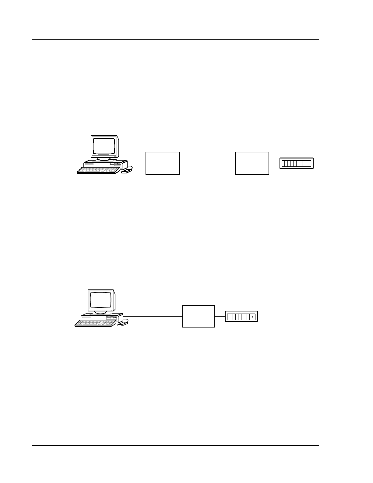
A basic MCN Remote Comparator Display system is shown in Figure 1. The
MCN Remote Comparator Display system consists of the Host Computer
Interface (HIB) Module and any MCN Comparator I/O Module (such as an AIB or
CIB). The PC runs the MCN Remote Comparator Display software (MCN RCD)
described in this manual. This manual covers the installation and operation of the
software. Details of the HIB (hardware installation and setup) are found in the
HIB reference manual (see reference 2). Also, the MCN system manual
(reference 1) contains more details about the MCN comparator display system.
REMOTE PC
COM 2
COM 1
HIB
MCN NETWORK
COMPARATOR
I/O
MODULE
COMPARATOR
CA-80048-100
Figure 1 - MCN Remote Comparator Display System
Higher Performance System
Some systems may require higher performance for their monitoring and control
system. The HIB module can be replaced by a PC ISA bus card that plugs into the
backplane of the PC. This plug in card is called a PCLTA card and it connects
directly to the MCN network, as shown in Figure 2. Details of the PCLTA
(hardware installation and setup) are found in its technical reference manual (see
reference 4). The PCLTA card can only be used in local monitoring applications.
COMPARATOR
CA-80237-100
COM 1
MCN NETWORK
COMPARATOR
I/O
MODULE
Figure 2 - MCN System with PCLTA Card
68-10856-210
1
Page 8

MCN Remote Comparator Display Introduction & Overview
CTI Products, Inc.
General Purpose I/O Devices require General Purpose Monitoring
and Control Function
The MCNRCD software can also monitor general purpose I/O devices connected
to CIB or IOB modules. Typical devices are:
• Door alarm inputs
• Generator run inputs
• Equipment failure inputs
• Relay control outputs
• Transmitter main/standby controls
General Purpose I/O Devices require different status indications than comparators
( “On/Off/Fail” versus Vote, Receive, Disable, Fail). Section 9 of this manual
describes how to provide custom status indications for general purpose I/O
functions using the status text categories and sub-categories.
Software Provided
Two programs make up the MCN RCD software package. They are:
• MCNCFG.EXE - the configuration program
• MCNRCD.EXE - the runtime Remote Comparator Display program
The MCNCFG.EXE program is run by an engineer or technician to build the
configuration files when the system is installed or changed. The MCNRCD
program is run by a dispatcher or technician to display the status of the voting
system.
The MCNRCD.EXE software allows the operator to see which receivers are
receiving, voted, disabled, failed or in an error condition on the PC. It also allows
the operator to monitor and disable receivers with the Force Vote and Disable
functions.
The MCNRCD.CFG file is an ASCII text file that the engineer or technician can
edit to change the configuration of several option parameters used by MCNRCD
software. This file may be edited by any text based editor program.
1.1 Network Interface Support
The MCN RCD software package can use any version of HIB modules or the
PCLTA card for the interface between the PC and the MCN network. The
PCLTA card and early versions of the HIB module do not provide modem
support. You can determine if you have an early HIB module by looking at the
model number found on the rear of the HIB module. All HIB modules have a unit
number of S2-60081-xxx. If the ‘xxx’ number is less than 200 you have an early
version HIB module.
68-10856-210
2
Page 9

MCN Remote Comparator Display Introduction & Overview
CTI Products, Inc.
Early HIB modules (‘xxx’ is less than 200):
• Support only local operation with MCNRCD. Skip all modem
references in this manual.
• External module that connects to one of the PC’s COM ports.
• Requires device driver LDVSLTA.SYS to be loaded by your PC’s
CONFIG.SYS file (see section 5).
All other HIB modules (‘xxx’ is 200 or greater):
• Support both local and remote operation with MCNRCD.
• External module that connects to one of the PC’s COM ports.
• Requires device driver CTIHIB.SYS to be loaded by your PC’s
CONFIG.SYS file (see Section 5).
PCLTA Interface:
• Support only local operation with MCNRCD. Skip all modem
references in this manual.
• Internal interface card that plugs into an ISA bus slot in the PC.
• Requires device driver LDVPCLTA.SYS to be loaded by your PC’s
CONFIG.SYS file (see Section 5).
1.2 System Hardware Requirements
Two components are required for the MCN RCD system.
1. Host Computer Interface Module (HIB) or PCLTA interface card
2. A PC to run the MCNRCD software with the following minimum
system configuration:
• 25 MHz 386 DX PC for 1 to 9 Comparator I/O Modules
50 MHz 486 DX PC for 10 to 20 Comparator I/O Modules
• EGA or VGA adapter and monitor
• 2 MB RAM (if running from DOS)
• 2 MB free disk space for program and support files
• 5 to 100 MB additional free disk space if logging Status data
• 5 to 10 MB addtional free disk space if logging Errors
• Microsoft or Logitech mouse (optional)
• One open serial port (for HIB use)
• One open full-size ISA slot (for PCLTA use)
• MS-DOS 5.0 or higher
UART Requirements
For applications using the HIB module with a PC serial port, CTI Products
recommends that you have a 16550 type UART. This UART has a 16 byte FIFO
(First In First Out) buffer for the receiver that is used to prevent UART overrun
errors. If your COM port uses a 16450 or 8250 type UART, then you may not be
or
68-10856-210
3
Page 10

MCN Remote Comparator Display Introduction & Overview
CTI Products, Inc.
able to operate the MCNRCD software at the highest baud rate (38400 bps). You
may have to run at either 14400 bps or 9600 bps.
If your COM port uses a 16450 or 8250 type UART, and you are running at 38400
bps, and you get the HIB communication error screen (see section 7.2.2.1), try
running the MCNRCD software at 1400 bps or 9600 bps (remember to change the
HIB’s baud rate selection switches to match the new data rate and then reset the
HIB module).
Modem Requirements
Modems may be used to create a remote comparator display system. CTI
Products, Inc. recommends the following:
• V.34 (28.8 K) modems with V.42bis or MNP 5 data compression for
best system performance in systems with 10 or more Comparator I/O
Modules.
• V.32bis (14.4 K) modems with V.42bis or MNP 5 data compression
for better system response in systems with 1 to 9 Comparator I/O
Modules.
• V.32 (9600) modems with data compression for normal system
response in systems with 1 to 9 Comparator I/O Modules.
See section 10 for additional modem information, including specific modems that
have been tested and verified to operate with MCNRCD.
1.3 Reference Documents
1. Monitoring and Control Network System Manual
Part Number S2-60425
2. Host Computer Interface Module Hardware Reference Manual (HIB)
Part Number S2-60427
3. TSAM Interface Module Hardware Reference Manual (TIB)
Part Number S2-60469
4. PCLTA Interface Card Hardware Reference Manual
Part Number S2-60648
5. I/O Control Module Hardware Reference Manual (IOB)
Part Number S2-60630
68-10856-210
4
Page 11

MCN Remote Comparator Display Theory of Operation
CTI Products, Inc.
2. Theory of Operation
This section describes the operation of the MCN Remote Comparator Display
software in an MCN comparator display system.
2.1 Comparator Status
The Comparator I/O Module (such as an AIB or CIB) accepts the VOTE,
RECEIVE, DISABLE, and FAIL receiver status indicators from the comparator.
It sends status messages to the HIB or PCLTA. The HIB or PCLTA passes the
messages over the PCs serial port to the MCNRCD software. The MCNRCD
software controls the VOTE, RECEIVE, DISABLE, and FAIL status display for
each receiver on the screen.
2.2 Controlling the Comparator
The MCNRCD software monitors the mouse and/or keyboard for VOTE and
DISABLE commands. When a VOTE or DISABLE command is activated, the
MCNRCD software sends a FORCE VOTE or DISABLE command to the
Comparator I/O Module. The Comparator I/O Module will then generate the
proper FORCE VOTE or DISABLE/ENABLE signal to control the comparator.
2.3 Transmitter Status Monitoring and Control
To provide transmitter status monitoring and control, your MCN system must also
include CTI Product’s Transmitter Steering Audio Matrix (TSAM) device along
with the MCN TIB Module (TSAM Interface Module) (see reference 3).
The MCNRCD software can display transmitter status information along with the
corresponding receiver’s status information. You can simultaneously view the
receiver’s current status along with the current state of the corresponding
transmitter (whether it is selected or not).
The MCNRCD software can also force a particular transmitter to be the active
transmitter by FORCE VOTING the receiver associated with that transmitter.
MCNRCD will display a status of
currently being FORCE VOTED and that the transmitter is active.
Tx/Vote
for that receiver to indicate that it is
68-10856-210
5
Page 12

MCN Remote Comparator Display Quick Start
CTI Products, Inc.
3. Quick Start
We recommend that you first set up the entire system, including PC, modems,
HIB or PCLTA, Comparator I/O Device, and any other equipment in the same
room to verify system cabling and operation. After the system is up and running,
install the individual items at their proper locations.
To install the system, do the following steps in order:
1
. Read section 4 of this manual.
2
. Install the MCN Remote Comparator Display software on the computer,
modify your CONFIG.SYS file to load the proper device driver, and re-boot
the computer. See section 5.1 of this manual.
3
. Modify your AUTOEXEC.BAT file if required. See section 5 of this manual.
4
. Install the HIB or PCLTA. Connect the PC to the HIB. Refer to the hardware
reference manuals of the HIB (reference 2) or PCLTA (reference 4) and the
MCN system manual (reference 1) for details about module installation.
5.
Connect the HIB or PCLTA to the Comparator I/O Module using the MCN
network cable. Refer to the hardware reference manuals of the Comparator
I/O Module, as well as the MCN system manual (reference 1) for details about
module installation.
6
. Run the MCN Remote Comparator Display (RCD) program using the pre-
built screen and module set files to verify the proper software and hardware
installation. The command line to execute is:
MCNRCD DEFAULT
7
. If you have dial-up modems, install them now and test them with your files.
a)
Make sure your modems are configured properly. See section 10 for
more details.
b)
Connect the HIB modem to the HIB. See sections 10.2.1 and 10.4 for
connection information.
c)
Connect the PC modem to the PC.
d)
Connect the modems to the phone lines. See the Testing Local Back to
Back Modems part of section 10 for more details.
8
. Run the MCNCFG program to configure the MCN Group Configuration Files
and MCN Screen Files for your system and test the system with your custom
files. Refer to section 6.2 for more details.
9.
After testing your system locally, finish the permanent installation of your
system.
If you move a PC with a dial-up modem to a phone line with a different access
code (like Dial 9 for an outside line), you will have to change the dialing string in
the MCN Screen File.
68-10856-210
6
Page 13

MCN Remote Comparator Display MCNRCD & MCNCFG Basics
CTI Products, Inc.
4. MCNRCD & MCNCFG Basics
4.1 Using Menu Commands
To access the menu commands, click the menu item with the left mouse button.
To use the keyboard to access menu commands, press the A key and the
highlighted letter for the menu command.
For example, to access the File menu, click the mouse cursor on the File option on
Af
the menu bar or press
Some menu commands may not be valid at certain times. When a command is
inactive, its text appears as dark gray text on the light gray menu background.
key combination on the keyboard.
When choosing a file from a file list box, highlight the file and then press
double-click on the filename with the mouse.
4.2 Configuration Files
A number of configuration files are used by the MCN Remote Comparator
Display runtime program (MCNRCD) and configuration program (MCNCFG).
Before you begin, read the following sections which describe the purpose of these
files.
4.2.1 M CN Group Configuration Files <filename>. GCF
An MCN Group contains up to 16 different MCN modules (Module numbers 0
through F), as defined in the
1. The MCN Group Configuration File (.GCF extension) defines all receivers
contained in a single MCN Group.
MCNRCD only supports the first 8 receivers (bank 0) of any Comparator I/O
Module, so a single GCF file supports a total of 128 receivers (8 receivers x 16
modules) in a single Group.
When a GCF file is created, a Group number must be assigned to the file (the
default is Group 0). The Group number must correspond to the MCN Group
number assigned to the Comparator I/O Modules that will be monitored and
controlled by MCNRCD.
MCN Comparator Display System Manual
E
or
, reference
Each receiver in the GCF file is defined by a receiver name and a channel name.
The MCNCFG program allows you to create as many Group Configuration Files
as are needed.
68-10856-210
7
Page 14

MCN Remote Comparator Display MCNRCD & MCNCFG Basics
CTI Products, Inc.
4.2.2 MCN Screen Files <filename>.M SF
Each screen that you want to display requires a MCN Screen File (.MSF). The
MCN Screen Files include the following:
• Module address of the HIB
• Which MCN Groups to display (up to 4)
• Screen Name
• Channel Title information
• Receiver Placement on the screen
You can make multiple MCN Screen Files that all use the same GCF
configuration files if all your receivers won’t fit on one screen. You can use
multiple screens to break down the receivers into a logical grouping of channels
(Police, Fire, Maintenance, etc.).
The program will handle up to 50 MCN Screen Files.
4.2.3 M odule Configuration Files <filename>. MCF
Each module in a GCF file has variable information associated with it. This
module information is entered using the Module Config command under the
menu. The Module Configuration File includes the following:
• Module descriptions
Edit
• Status text categories assigned to each module
The MCF file is automatically created when a GCF file is saved. The filename
used for the MCF file is the same as the GCF filename.
4.2.4 M odem Configuration File (MODEM .INI)
The Modem Configuration File includes commands specific to the particular
modem being used. This file and its entries are described in section 10.
4.2.5 Remote Comparator Di splay Configuration File (MCNRCD.INI)
This file holds the Error Logging settings that are selected in the MCNRCD
program. The MCNRCD program reads this file on start-up and uses those error
logging options. MCNRCD automatically updates this file whenever you change
Logging options (Status/Error).
4.2.6 M CN Error Log File (MCNERR.LOG)
This file holds Error log entries in ASCII text form. Selectable file size range of 1
to 10 MB via the command line option switch: /En ( n = 1 to 10). Default size is
1 MB. Each error log entry uses 107 bytes. A warning indication is given on each
log when the MCNERR.LOG file reaches 90% full. At 100% capacity, the error
log file will automatically be rebuilt down to 50% of the command line option
switch (/En) file size The most recent error logs will make up this reduced file.
See section 7.6.1 for more details.
68-10856-210
8
Page 15

MCN Remote Comparator Display MCNRCD & MCNCFG Basics
CTI Products, Inc.
4.2.7 M CN Stati s ti cs Log File (MCNSTAT.LOG)
This file contains the statistics log entries in an ASCII text form. See section
7.6.2 for more information about statistics logging.
4.2.8 M CN Text Configuration File (MCNRCD. CFG)
This file holds the receiver status text messages that are displayed for the VOTE,
RECEIVE, DISABLE and FAIL states. This file can be changed so that you can
customize the displayed status messages. See section 9 for more information.
4.2.9 HIB Confi gur ation Program (HIBCNFG.EXE)
This file allows you to program a modem initialization string into the HIB.
Whenever the HIB is reset, and configured for remote operation, it sends this
string to the modem. See section 10.2.1 for more information.
68-10856-210
9
Page 16

MCN Remote Comparator Display Installation
CTI Products, Inc.
5. Installation
5.1 Installing the Remote Comparator Display Software
To Install the Remote Comparator Display Software
1. C:> MD CTI
2. C:> CD CTI
3. Insert
4. C:\CTI> COPY A:*.*
5. Modify your CONFIG.SYS file as shown in section 5.2 of this manual.
6. Modify your AUTOEXEC.BAT file as shown in section 5.4 of this manual.
7. If you are using transmitter steering (your system includes TIB modules),
8. Re-boot to have the changes take effect.
CTI MCN Remote Comparator Display
copy the file TXSTEER.CFG to MCNRCD.CFG so that you have the
transmitter steering status messages. The standard configuration file,
NORMAL.CFG does not include the transmitter steering information.
5.2 Loading the Device Driver
A device driver file must be loaded by your CONFIG.SYS file before the runtime
comparator display software MCNRCD.EXE can be run. The command line for
the device driver should have been edited into your CONFIG.SYS file when the
MCN network interface module (either the HIB or the PCLTA card) was installed
in the system. If you have not loaded the device driver, modify your
CONFIG.SYS file to add the appropriate command line and then re-boot your PC.
E
E
disk in A:
E
Refer to the HIB or PCLTA hardware reference manual of the MCN network
interface device you are using for instructions on loading the device driver. Each
type of network interface device uses a different device driver file. You may be
able to load the device driver in high memory to conserve conventional memory.
If you attempt to run MCNRCD.EXE without loading this device driver,
MCNRCD will show an error when a screen file is loaded and then will exit back
to DOS.
5.3 Additional CONFIG.SYS File Changes
In addition to the device driver additions, be sure your C:\CONFIG.SYS file
includes the following minimum Files and Buffers:
FILES=20
BUFFERS=20
If you use a MOUSE.SYS mouse driver, make sure its entry is in CONFIG.SYS.
If you use a serial mouse, be sure its COM port does not conflict with the serial
port for the HIB. Be sure to re-boot the computer after any changes.
10
68-10856-210
Page 17

MCN Remote Comparator Display Installation
CTI Products, Inc.
5.4 Modifying the AUTOEXEC.BAT File
If you use a MOUSE.COM mouse driver, make sure its entry is in
AUTOEXEC.BAT. If you use a serial mouse, be sure its COM port does not
conflict with the serial port for the HIB. Be sure to re-boot the computer after any
changes.
5.5 Netw ork Interface Installation & Cabling
The physical installation of the HIB module is covered in the HIB’s hardware
reference manual, reference 2. If you are using a PCLTA card instead of the HIB
module refer to the PCLTA manual (reference 4) for installation and cabling
instructions.
5.6 Modem Setup
We recommend using a Practical Peripherals PM144MT II modem for dial up
applications or a UDS V.3229 modem for leased line applications. Modem
configuration sheets are provided in section 10 for various modems that have been
tested.
See the modem manual for instructions on how to configure the modem.
See the
description of level setting and how to connect the modems in a back to back
configuration for testing.
When connecting the modem to your PC, make sure the modem is connected to
the PC’s COM port that is specified on the CTIHIB.SYS driver command line in
CONFIG.SYS.
Testing Local Back to Back Modems
5.6.1 Internal Modem Support
If you are using an internal modem in the PC, configure the modem so that it uses
the same COM port specified on the CTIHIB.SYS driver command line.
section of section 10 for a
11
68-10856-210
Page 18

MCN Remote Comparator Display Configuring a System
CTI Products, Inc. Using MCNCFG
6. Configuring a System -- Using MCNCFG
A basic remote comparator display system consists of a PC connected to a HIB or
PCLTA and one or more Comparator I/O Modules (see Figure 1).
An MCN Group Configuration file (.GCF extension) contains all of the receiver
information for MCN Comparator I/O Modules addressed into a single MCN
Group.
MCN Screen Files (.MSF extension) contain a list of receivers to be displayed on
the current CRT screen and where they will appear on the screen. Up to four
different MCN Groups can be monitored and controlled from the same MCN
screen file.
Up to 88 receivers can appear on the PC display. For many systems this will
allow an operator to view all of the receivers in a voting receiver system. On
larger systems as many as 50 screens can be created to display a system’s
receivers.
You will use the MCN Remote Comparator Display Configuration Program
(MCNCFG) to create and edit these files when you install or change your system.
6.1 Configuration Steps
To custom configure the MCN Remote Comparator Display software for your
radio system do the following:
1. Build an MCN Group Configuration File (GCF) for your
Comparator I/O Module(s):
a) Use Files New Group Configuration menu command to open a new
MCN Group Configuration File.
b) Enter Receiver Names and Corresponding Channel Name/Notes for
each receiver.
c) Use Edit Group Number to assign the two digit number (00-FE) of
the MCN Group that these receivers are located in (the default Group
number is 00). This number comes from the Group number of the unit
address assigned to the Comparator I/O modules. Refer to the MCN
system manual (reference 1) for information about module address
assignment.
d) Use Edit Module Config to enter the descriptions for each module
and change, if needed, the MCNRCD.CFG status text category that
will be used by the modules for their status message display.
e) Use the Files Save menu command to save the GCF file.
f) If you have more than one MCN Group in your system, repeat the
above procedure for each MCN Group.
12
68-10856-210
Page 19

MCN Remote Comparator Display Configuring a System
CTI Products, Inc. Using MCNCFG
2. Build a MCN Screen File (SCF):
a) Use the Files New Screen menu command to open a new MCN
Screen File.
b) The Active Group Files dialog box will appear. Press E to pop up a
list of GCF files. Select the GCF file(s) that you want to display on the
E
screen. Tab to <OK> and press
c) The Select Active Group File dialog box will be displayed. Select
the Group Configuration File you wish to work with first.
d) Enter Channel Titles using the Insert key.
e) Place receivers on the screen using the
receiver list.
f) If your MCN HIB module has a model number S2-60081-xxx where
‘xxx’ is the number 200 or greater (this number is found on the rear of
the module), set the GROUP and MODULE rotary switches to the unit
address you defined for the HIB (these switches are found on the rear
of the module. Skip to step h.
g) If your MCN HIB module has a unit number where ‘xxx’ is less than
200 or if you are using a PCLTA card, you must execute the Edit HIB
Address command to specify the MCN address of the HIB module or
PCLTA card that will be connected to this PC.
Program the Group and Module numbers that you defined for the HIB.
h) Use the Edit Screen Name menu command to add a screen name.
i) If you use a dial-up modem, use the Edit Dialing String menu
command to enter a dialing string (the phone number of the remote
HIB).
j) Use the Files Save menu command to save the MSF file.
The remainder of this section will walk you through the above steps. There are
some additional menu commands that will be covered later.
.
E
key and selecting from the
6.2 Starting the MCNCFG configuration program
1. Exit any application software you are running.
2. Change the current directory to C:\CTI
3. Type: MCNCFG
This will Start the MCNCFG configuration program and display a screen similar
to the one in Figure 3, but with just the menu bar.
E
6.3 Using the M CNCFG Menu Commands
The MCNCFG program commands are accessed through the programs pull-down
menus. These function similarly to the pull-down menus in many popular DOS
and Windows programs.
The Menu Bar is the top line of the screen. The Menu Bar is always visible. Each
item on the bar is the name of a pull-down menu. Press the H key to activate the
Menu Bar. The File Menu Name is now selected.
13
68-10856-210
Page 20
MCN Remote Comparator Display Configuring a System
CTI Products, Inc. Using MCNCFG
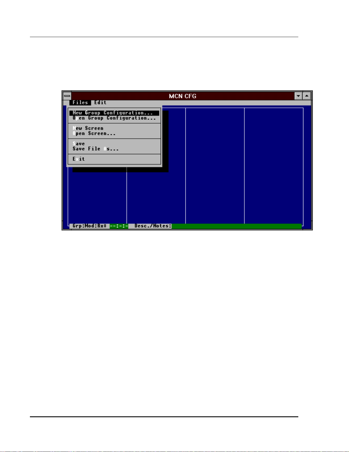
To get a complete list of the File Menu commands, press the f key. This displays
the pull-down File Menu as in Figure 3. Each of the pull-down menus has a short
cut activation key. This key is the intensified character in the menu name.
Pressing the H key + the intensified letter of the menu will activate menu.
Figure 3 - MCNCFG File Menu
With the mouse, each menu can be activated by clicking on the menu name. Once
the menu is activated, individual commands can be activated by clicking on them
with the mouse or by pressing the appropriate intensified shortcut key for that
command.
When choosing a file from a file list box, highlight the file and then press
double-click on the filename with the mouse.
6.4 Creating a New MCN Group Configur ation File
This is the first step in creating the configuration files for a new system. Select
the Files New Group Configuration menu command with the keyboard or
mouse. The MCNCFG program will bring up a blank module set configuration
screen with just the receiver numbers in the left hand column, as shown in Figure
4. A single MCN Group contains 16 unique Module numbers (0 through 9 and A
through F). The maximum number of receivers for a given module is 8.
Currently MCNRCD can only monitor and control receivers 1 through 8 (bank 0)
of any Comparator I/O Module. Section 6.4.2 gives more details about assigning
the group number.
E
or
14
68-10856-210
Page 21
MCN Remote Comparator Display Configuring a System
CTI Products, Inc. Using MCNCFG
If you were working on a module set or screen file and had not yet saved it when
you selected the Files New Group Configuration menu command, the program
will give you a chance to save it.
Figure 4 - New Group Configuration Screen
6.4.1 Group Configuration Screen Description
The Group Configuration screen has entries for a total of 128 receiver (8 receivers
x 16 different modules). It includes a Receiver Name field and a Channel Name /
Note field.
The configuration screen has entries for the modules within that MCN Group.
The receiver number shown in the left column of the Group Configuration Screen
is made up of three parts (Grp:Mod:Rx).
Grp
1.
2.
3.
is the MCN Group number (00-FE) assigned to the Comparator
I/O Module(s) that you will be monitoring. This number can be
changed by using the Edit Group Number command.
Mod
is the MCN Module number (0-F) assigned to the Comparator
I/O Module(s) that you will be monitoring. All 16 modules of a single
MCN Group are supported by a single Group Configuration File.
Rx
is the number of the receiver (1-8) for that Comparator I/O Module.
The MCN Remote Comparator Display software supports 8 receivers
(bank 0) per MCN Comparator I/O Module.
NOTE: The Group and Module numbers must match the address of the
Comparator I/O Module being configured.
15
68-10856-210
Page 22
MCN Remote Comparator Display Configuring a System
CTI Products, Inc. Using MCNCFG
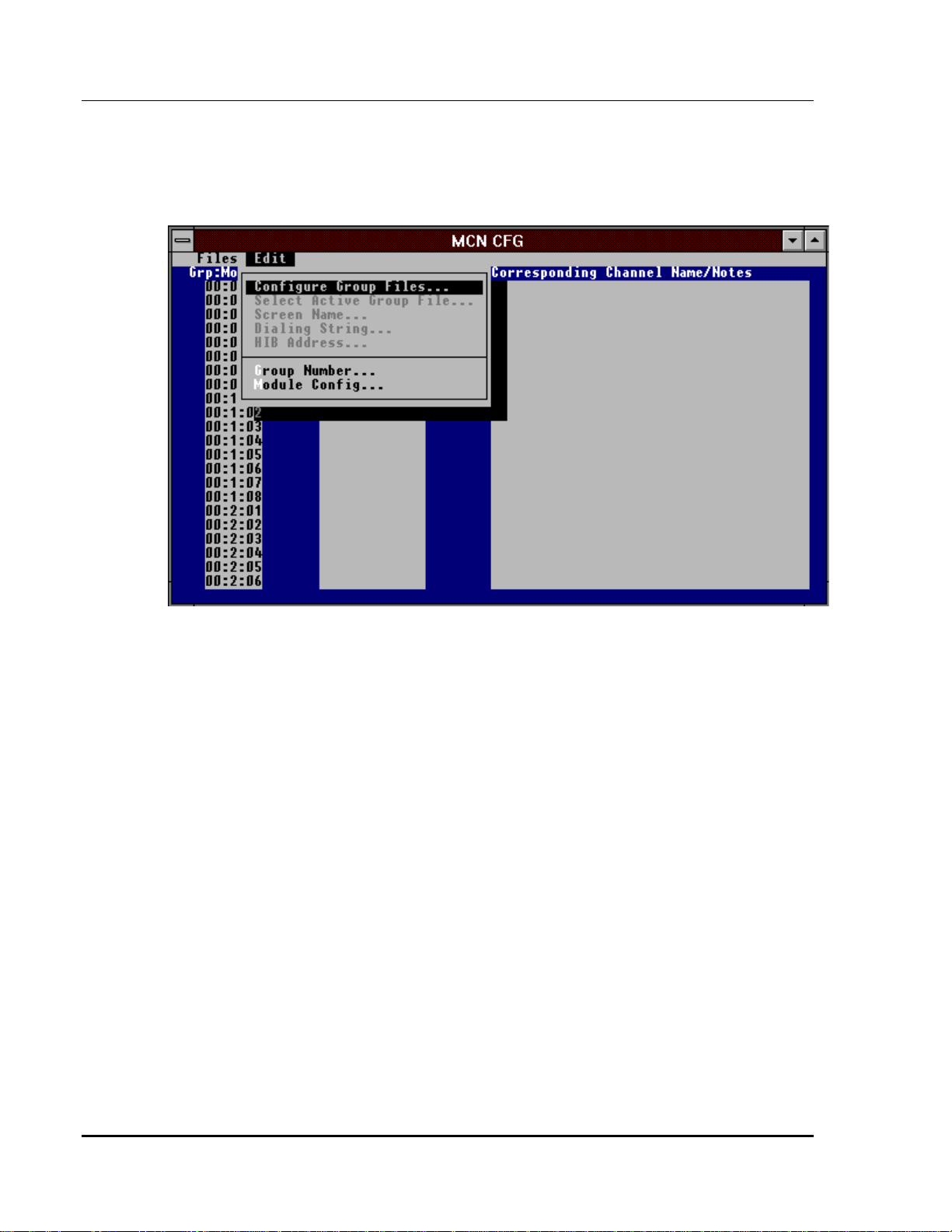
6.4.2 Defining a Group Number
Using the Edit Group Number menu command, you can define the MCN Group
for the Comparator I/O Modules being monitored. Figure 5 shows the pull-down
Edit Menu during Group Configuration.
Figure 5 - Group Configuration Edit List
Figure 6 shows the dialog box that appears when the Group Number menu
command is executed. Enter a new Group number in the range shown on the
screen. Again, this Group number is the Group number assigned to the
Comparator I/O Modules that will be defined in this Group Configuration File.
16
68-10856-210
Page 23
MCN Remote Comparator Display Configuring a System
CTI Products, Inc. Using MCNCFG
Figure 6 - Group Number Editing
6.4.3 Entering Receiver Names
Enter a descriptive name for each receiver controlled by the Comparator I/O
Modules. This will usually be a site name. The receiver name will be displayed
on the PC screen to identify the receiver. It is a 13-character alphanumeric field.
Typical entries may be "Comm Center", "North Union", "East Bend" and the like.
The Channel Name/Description is used to enter additional information about each
receiver. Entering text in this field is optional.
The Receiver Name will be used along with the Channel Name/Note and
Comparator I/O Module’s unit address in error logging printouts to identify a
particular receiver.
Note: When you are finished entering the Receiver Names or the Channel
Name/Note fields, be sure to hit E or move your cursor to another field. This will
enter the last entry into the database. If you save the file without doing this, you
may lose your last entry.
17
68-10856-210
Page 24

MCN Remote Comparator Display Configuring a System
CTI Products, Inc. Using MCNCFG
6.4.4 Entering Channel Name/Note Field
The Channel Name/Note field is a 39 character alphanumeric field used to
identify the channel for each receiver. When you build your Group Configuration
Files, enter a channel name or number for each receiver so you can identify the
channel for each receiver at a common site.
The Channel Name/Note field is also used for error logging printouts to identify
which channel on a Comparator I/O Module has a disabled or failed receiver.
You may find it helpful to include telephone circuit numbers or microwave
channel numbers in this field.
A typical radio system may have multiple RF channels that have receivers at
common sites, see the system configuration in Figure 12. This system has a
Comm Center
confusing if you haven’t uniquely identified the receiver with a Channel
Description in the Group Configuration File.
NOTE: If transmitter steering information is being monitored, your receiver
names could be over written by the status display messages whenever a receiver is
not in the idle state. When the receiver returns to the idle state, the entire receiver
name will be redisplayed.
receiver on both the East and West Police channels. This can be
6.4.5 Enteri ng Module Configuration Informati on
The status text category determines how the I/O lines on the I/O modules (CIBs
and IOBs) will be displayed on the PC. You will use the DEFAULT category
(Vote, Rx, Dis, and Fail) for most comparator applications. Other general purpose
I/O applications will need custom status text categories to display status messages
such as On/Off, Up/Down, etc.
Each CIB or IOB module can have its own status text category. These categories
are assigned to the module using the Edit Module Config menu command.
Using the Edit Module Config menu command, you can edit the configuration
information for each of the I/O Modules being monitored. Figure 5 shows the
pull-down
shows the edit screen that appears for the
Edit
Menu that gives the
Module Config
Module Config
menu option. Figure 7
option.
18
68-10856-210
Page 25
MCN Remote Comparator Display Configuring a System
CTI Products, Inc. Using MCNCFG
Figure 7 - Module Configuration Editing
When moving around this screen without a mouse, you must use the T key to
moved between selections. To exit the screen, press the T key until the cursor is
on the OK or CANCEL button and then press E.
6.4.5.1.1 Defining the Module’s Status Text Category
From this screen you can program in the status text category that you want used
for the Comparator I/O Module. This entry can be up to 10 characters long. The
category name entered must be a category name that you created in the
MCNRCD.CFG file. Section 9 provides details about the MCNRCD.CFG file
and status text categories. The category names entered are stored in the MCF file
that is created when you save the Group configuration.
If you are only going to use the default status text category for comparators (you
will not be creating any additional categories in the MCNRCD.CFG file), then
you will not have to edit this field for any module. When MCNCFG.EXE creates
the MCF file, it assigns the category name DEFAULT to all modules.
6.4.5.1.2 Entering a Module Description
From the
Module Config
screen you can also enter a description for each
module. This description can be up to 20 characters long. For example, you
might enter the building or rack location of each module. This information can
then be used as a troubleshooting aid to help locate modules quickly. The
descriptions entered are stored in the MCF file that is created when you save the
Group configuration.
19
68-10856-210
Page 26

MCN Remote Comparator Display Configuring a System
CTI Products, Inc. Using MCNCFG
6.4.6 Group Confi gur ation File Editing Keys
The table below lists the editing key commands available to edit the Group
Configuration File.
••••
RIGHT ARROW
RIGHT ARROW
The
character position to the right in the field.
R
R key moves the cursor non-destructively one
When the cursor reaches the end of the field, the
RIGHT ARROW
the cursor to the beginning of the next field.
••••
LEFT ARROW
LEFT ARROW
The
Q
Q key moves the cursor non-destructively one
character position to the left in the field.
When the cursor reaches the beginning of the field, the
LEFT ARROW
key moves the cursor to the beginning of the previous field
••••
UP ARROW
UP ARROW
The
Z
Z key moves the cursor to the same column of the
previous line (field).
••••
DOWN ARROW
DOWN ARROW
The
Y
Y key functions identically to
UP ARROW
, except it
moves the cursor to the next line.
••••
RIGHT TAB
RIGHT TAB
The
T
(Forward) T key selects the next field. If you are
positioned at the bottom of the screen, It will scroll the screen up one
line and move to the first column of the next line.
••••
LEFT TAB
The
BT
LEFT TAB
)
BT
(
key functions identically to the Forward Tab,
except it selects the previous field.
R key moves
Q
••••
PGUP
O
P
PGU
O will display the previous screen of receivers.
••••
PGDN
N
PGDN
N will display the next screen of receivers.
••••
HOME
Pressing the
HOME
Key will move the text cursor to the beginning of
the current field.
••••
END
This Key moves the text cursor to the end of the current field.
20
68-10856-210
Page 27

MCN Remote Comparator Display Configuring a System
CTI Products, Inc. Using MCNCFG
••••
CTRL+ HOME
IF you press
CTRL+HOME
at the same time the cursor is moved to the
beginning (receiver #1) of the receiver list.
••••
CTRL
CTRL
+
+
END
END
moves the text cursor to the last receiver (receiver #152) of
the receiver list.
CTRL
•
CTRL+D
+D (D
copies the text (either a receiver name or a channel
ITTO
)
description) from the line above to the current line. This editing key is
useful when your receivers or channel descriptions have common text.
Instead of having to re-type the common text for each line, you simply
enter it once and the use the
CTRL+D
key to copy the text from the
line above to the current line. Then, you simply edit the variable text
on the new line. If the cursor is on the top line of the screen, the
CTRL+D
••••
INSERT
The
When the
INSERT
key does nothing.
Key
key is used to toggle between Insert and Overtype mode.
NSERT
I
key is pressed, the cursor toggles between a blinking
underscore (overtype mode) and a blinking block (insert mode).
••••
DELETE
DELETE
= Key
erases one character at the current cursor position. This differs
from the Backspace key which deletes a character to the left of the
current cursor position.
••••
SHIFT+INSERT
Key
This Inserts a blank entry at the current receiver number location and
moves all of the following receivers down one row. All receiver
numbers following the new entry are incremented by one and pushed
down the list.
••••
SHIFT+DELETE
Key
The current receiver entry is deleted and all the receivers numbers
following the deleted entry are decremented by one, thereby moving
them up the list.
••••
ESC X
The
Key
ESC
X key (Escape) allows the operator to exit out of the current
function and return to the preceding command menu.
21
68-10856-210
Page 28
MCN Remote Comparator Display Configuring a System
CTI Products, Inc. Using MCNCFG
6.4.7 Inserting and Deleting Receivers
If you make a mistake by skipping or duplicating a receiver when entering your
receivers, you can insert or delete a receiver at the current position of the database.
Use the following editing keys to Insert or Delete receivers:
SHIFT+INS
This inserts a blank entry at the current receiver number location and moves all of
the following receivers down one row.
SHIFT+DEL
The current receiver entry is deleted and all the receivers following the deleted
entry are moved up the list.
6.4.8 Saving the Group Confi gur ation File
When you are finished building your Group Configuration File, use the File Save
menu command.
If this is a new Group Configuration File, the File Save As dialog box will come
up and you will be prompted for a file name. Enter a standard DOS file name
without the extension. The program will save the file with an .GCF extension.
You will get an error message if you enter the wrong extension.
Figure 8 - Saving a New Group Configuration File
When the GCF file is saved, MCNRCD automatically saves the MCF file to store
your module configuration information.
68-10856-210
22
Page 29
MCN Remote Comparator Display Configuring a System
CTI Products, Inc. Using MCNCFG
6.4.9 Example
LOCAL PC
P/S
IN
T
OUT
CIB
IN
OUT
CIB
IN
COM 2
COM 1
HIB
P/S
IN
OUT
T
OUT
CIB
Figure 9 - MCN RCD Group Configuration Example
In this system, assume that the four MCN modules have the following unit
addresses assigned to them:
• CIB #1 (connected to comparator 1) is Group 00, Module 0
• CIB #2 (connected to comparator 2) is Group 00, Module 1
• CIB #3 (connected to comparator 3) is Group 00, Module 2
• HIB is Group 80, Module 0
COMPARATORS
1
2
3
CA-80041-100
These addresses were assigned during system installation so that all of the CIBs of
the system were addressed to the same MCN Group. Therefore, only one Group
Configuration File needs to be created for the system. If the CIBs were addressed
into three different MCN Groups, then three Group Configuration Files would
have to be created, one for each CIB.
To create a Group Configuration File for this system, do the following:
1. Execute the Files New Group Configuration command
2. Execute the Edit Group Number command
3. Enter 00 as the new Group number
4. Select the OK box or press
E
5. Enter receiver names and channel names/notes for the following
receivers (see Figure 10 and Figure 11):
• 00:0:1 through 00:0:8 (receivers for CIB #1)
• 00:1:1 through 00:1:8 (receivers for CIB #2)
• 00:2:1 through 00:2:8 (receivers for CIB #3)
6. Execute the File Save command
7. Enter the file name SYSTEM1
23
68-10856-210
Page 30

MCN Remote Comparator Display Configuring a System
CTI Products, Inc. Using MCNCFG
Figure 10 - Example Group Configuration
Figure 11 - Example Group Configuration (continued)
Figure 10 and Figure 11 show an example of the receiver names entered for this
system. Notice that the
Grp
field, entered in step 3 above, of the receiver names
is 00.
68-10856-210
24
Page 31

MCN Remote Comparator Display Configuring a System
CTI Products, Inc. Using MCNCFG
Now you have a file named SYSTEM1.GCF that defines all of the receivers for
this system. Section 6.5.1 describes how this file will be used to create a MCN
Screen File.
6.5 Building a Display Screen for your system
Now that you have your Group Configuration File built, it’s time to start building
a display screen. A typical screen is shown below. A description of the different
fields will follow.
Figure 12 - Typical Fully-Configured Display Screen
File Name Display
MCNCFG displays the name of the currently loaded file on the right of the menu
bar. When a new file is being edited, the display remains blank until it is saved
with a valid file name.
Receiver Screen Locations
The screen has 88 display positions. Each display position can be used to display
a channel title or a receiver name.
Receiver Module Set Numbers
Group configuration file numbers (G1-G4) corresponds to the Group
Configuration File the receiver is defined in.
Receiver Status Line
When editing a screen file, MCNCFG displays a receiver status line on the bottom
of the screen. Moving the keyboard cursor to a receiver on the display screen
shows additional information about that receiver. The status line displays the full
68-10856-210
25
Page 32

MCN Remote Comparator Display Configuring a System
CTI Products, Inc. Using MCNCFG
receiver number, including the MCN Group and Module number of the
Comparator I/O Module for the receiver and receiver Desc./Notes.
Tip: It is a good idea to move the cursor over each receiver on the screen and
use the Channel Description field at the bottom of the screen to verify the proper
channel assignments after you are finished building your screen.
6.5.1 Opening a new MCN Screen File
To create a new MCN Screen File, select the Files New Screen menu command.
This command will clear the screen and display the Active Group Files Dialog
Box as shown in Figure 13.
Figure 13- Configure Active Group Files Dialog Box
If you try to open a new screen and have not yet saved your work, a Save
Changes warning dialog box will be displayed.
26
68-10856-210
Page 33

MCN Remote Comparator Display Configuring a System
CTI Products, Inc. Using MCNCFG
6.5.2
Specify Group Configurations
When you build a screen, you must select the Group Configuration File(s) that
contain the receivers you want to monitor and control. Up to four different MCN
Groups can be monitored and controlled in a single MCN Screen File.
To Select Group Configuration Files:
1. The cursor will start in Group File 1.
2. Press the E key or left-click the mouse in the Group File 1 box. A list of
Group Configuration Files will appear.
3. Select the Group Configuration File for the Group that this screen will
monitor. Double click on your choice or press E.
Note: Repeat this procedure if you want to monitor and control receivers from
more than one MCN Group.
4. Press the T key until the <OK> button is highlighted and press E. (You can
also use the mouse to click the < OK > button.)
Dialog Box
Figure 14 - Selecting a Group Configuration File
Normally the Active Group Files dialog box is used only when you start to build
a new MCN Screen File. You can also bring up the Active Group Files dialog
box using the Edit Group Configurations menu command to change the GCF
files that a screen refers to. If you change a Group File name using the Edit
Group Configurations menu command, any receivers names from the original
Group Configuration File that were placed on the screen will be changed to the
receiver names from the new Group Configuration File. When you press the
<OK> button, the MCNCFG program will bring up the Set Active Group File
Dialog box.
68-10856-210
27
Page 34

MCN Remote Comparator Display Configuring a System
CTI Products, Inc. Using MCNCFG
6.5.3 Selecting One Group to Work With --
When you place receivers on a display screen, you can work with receivers from
only one Group file at a time.
To select Group file 1, press E to select that .GCF file. Select one of the other
Group files to work with by using the Z or Y keys. Press the T key to get to the
OK button and then press E. You can also select a Group file with the mouse.
If you need to place receivers from more than one Group on the same screen,
place the receivers from one Group first and then use the Edit Select Active
Group File menu command to select a different Group to work with.
Set Active Group
Dialog Box
Figure 15 - Set Active Group File Dialog Box
6.5.4 Assigning a Unit Address to the HIB or PCLTA
As stated in the MCN System Manual, reference 1, section
Address
If your HIB module has a model number S2-60081-xxx where ‘xxx’ is 200 or
greater, the HIB’s unit address is set by the rotary switches located on the rear of
the module. See reference 1 for details about these switches. You can then skip
using the Edit HIB Address command.
If your HIB’s model number has an ‘xxx’ number less than 200 or if you are using
a PCLTA card, then you must use the Edit HIB Address command to enter the
unit address of the HIB because the HIB module does not have the rotary switches
to do this. The unit address of the HIB is programmed into the MCN Screen File
, all MCN modules must have a unique address assigned to them.
28
Setting the Unit
68-10856-210
Page 35

MCN Remote Comparator Display Configuring a System
CTI Products, Inc. Using MCNCFG
using the Edit HIB Address command. Figure 16 shows the dialog box that
appears.
Figure 16 - HIB Address Entry Dialog Box
To enter a new address for the HIB or PCLTA, do the following:
1. For the Group number, enter a number between 00 and FE (hex). The
default Group number is 80 (hex).
T
2.
over to the Module number field and enter a number between 0 and
F (hex).
T
3.
over to the <OK> button and press E to save the new address.
Every screen file must have the correct HIB or PCLTA address programmed.
All MCN modules in a system must have its own unique address. Each
MCNRCD screen files on a single PC should have the same unit address assigned
to them and all PCs should be assigned to a unique unit address. When assigning
addresses to the modules, you may want to reserve a single MCN Group (or
cluster of Groups if you have more than 16 HIBs and PCLTAs in the system) for
all of the HIBs and PCLTAs. Typically, Group numbers 80 and up are used for
HIBs and PCLTAs.
6.5.5 Adding Channel Titles to the Display Screen
If you display multiple channels on a screen, you will probably want to add
channel titles to help the user identify the receivers. Channel Titles can be 18characters long.
29
68-10856-210
Page 36

MCN Remote Comparator Display Configuring a System
CTI Products, Inc. Using MCNCFG
Tip:
As you build your display, you can add Channel Titles and place Receivers
in whatever order you want. (You don’t have to add all the Channel Titles first.)
It is usually easier to enter a Channel Title and place the receivers for that channel.
You can then determine where to place the Channel Title and Receivers for the
next channel.
To Add a Channel Title To the Screen
1 Select the position where you wish to place a
Channel Title
by moving the
keyboard cursor to that screen location or by clicking on the location with the
right mouse button. Press
INSERT
. The keyboard cursor will change color to
the Channel Title color.
2 Type in the Channel Title that you want to appear at that screen position. You
can use spaces to center up the title. After typing the title press E. The title
then changes color to the keyboard cursor color. Move the keyboard cursor to
see how the Channel Title will normally be displayed.
30
68-10856-210
Page 37

MCN Remote Comparator Display Configuring a System
CTI Products, Inc. Using MCNCFG
6.5.6 Placing Receivers on the Screen
Once you have either created a new Screen File or opened an existing one, you are
ready to determine where the receivers will appear on the screen. The MCNCFG
Program is now in the
Place Receivers
mode.
Figure 17 - Placing Receivers on a Display Screen
To Place a Receiver on the Screen
With the Keyboard...
1. Select the position where you wish to place a receiver by moving the
keyboard cursor to that screen location.
2. Press E. This brings up the receiver list box as shown in Figure 17.
3. Select a receiver to be displayed in that position. Use the keyboard cursor
movement keys to highlight the desired receiver and then press E to select
the desired receiver.
TIP: After you place a receiver, the keyboard cursor automatically moves to the
next screen position. Pressing E brings up the receiver list box and automatically
highlights the next receiver in the list. Pressing
screen. By repeatedly pressing
in this way you can quickly place receivers on
E
E
again places the receiver on the
the screen in the order they appear in the list box.
31
68-10856-210
Page 38

MCN Remote Comparator Display Configuring a System
CTI Products, Inc. Using MCNCFG
With the Mouse...
1. Select the position where you wish to place a receiver by clicking the left
mouse button on that area of the screen. The Keyboard cursor is moved to the
area you selected and the receiver list box appears.
2. Select a receiver to be displayed in that position. To select a receiver use the
mouse to double click on the desired receiver name.
TIP: You can use any combination of keyboard and mouse controls to place
receivers. As an example you can pick screen positions with the keyboard cursor
by pressing E. Then pick the receiver from the list box by using the scroll bars
and double clicking with the mouse.
6.5.7 Deleting a Receiver or Channel Title From the Screen
With the Keyboard...
1 Select the receiver name or channel title you wish to delete by moving the
keyboard cursor to that screen location. Press the = key.
With the Mouse...
1 Move the mouse cursor to the name or channel title you wish to delete.
2 If you have a two or three button mouse, press the right and left mouse buttons
together, and then release them.
If you have a three button mouse, press the middle button then release.
6.5.8 Edit Screen Name
You can enter a screen name for each screen that you build. The screen name will
be displayed on the top line of the screen in the Remote Comparator Display
(MCNRCD) program. This command can only be executed when a valid screen
file (*.MSF) is loaded.
Note: If you plan to display only one radio channel on a screen, you can enter the
channel name in place of the screen name. You can then use all 88 receiver
positions for actual receivers.
To enter a screen name:
1. Use the Edit Screen Name menu command. The Screen Name dialog box
will appear.
2. Enter the screen name in the edit box. You can use spaces to center the screen
name.
3. Use the T key to highlight the <OK> button and press E to confirm your
selection. You can also use the mouse to select <OK>.
4. The new screen name will appear on the menu line of your screen.
32
68-10856-210
Page 39

MCN Remote Comparator Display Configuring a System
CTI Products, Inc. Using MCNCFG
Figure 18 - Entering a Screen Name
6.5.9 Enteri ng the HI B Telephone Number / Modem Dialing String
If you are using the MCNRCD and HIB with dial-up modems, you must enter a
modem dialing string (the phone number for the HIB location) into the screen file.
To program the dialing string for this screen:
1 While the screen file is loaded press H, e, d or pick the Edit Dialing String
menu command with the mouse. If a screen file is not loaded this command
is inactive.
2 Type the "AT" dialing command for your modem, including PBX access
codes, phone number.
33
68-10856-210
Page 40

MCN Remote Comparator Display Configuring a System
CTI Products, Inc. Using MCNCFG
Figure 19 - Entering the HIB Dialing String
The dialing string consists of:
Description Typical Entry
1. Modem Attention Code ATDT
2. PBX Access Codes & Wait (if needed) 9W
3. HIB Modem Telephone Number 555-1234
The above example would be entered as: "ATDT9W555-1234" (Don’t enter the
quotes.)
For more information on your modems dialing commands consult your modems
documentation and section 10 for more details.
Tip:
An easy way to test your modem dialing commands is to use a terminal
program such as Procomm. You can try different dialing strings to make sure they
work. Note that if you try calling the HIB with a terminal program such as
Procomm, you will see strange control characters coming back to you when the
modems connect.
34
68-10856-210
Page 41

MCN Remote Comparator Display Configuring a System
CTI Products, Inc. Using MCNCFG
6.5.10 Saving the MCN Screen File
When you are finished building your screen, you must save the MCN Screen File.
Tip:
receiver on the screen and use the Channel Description field at the bottom of the
screen to verify the proper channel assignments.
Use the Files Save menu command to save your MCN Screen File.
If this is a new MCN Screen File, the File Save As dialog box will come up and
you will be prompted for a file name. Enter a standard DOS file name without the
extension. The program will save the file with an .MSF extension. You will get
an error message if you enter the wrong extension.
After you save a screen file, the file name will appear on the right side of the
menu bar.
6.5.11 Example
Using the system example shown in Figure 9 and the Group Configuration File
SYSTEM1.GCF that was created in section 6.4.9, we will now create a screen file
that can be used to monitoring and control of the system. To create this file, do
the following:
Before you save the file, it is a good idea to move the cursor over each
1. Execute the Files New Screen command, the cursor will start in
Group File 1
2. Press the E key to get the list of Group Configuration Files.
3. Using the arrow keys, position the highlighted bar on the file
SYSTEM1.GCF and press the E key to select the file.
4. Press the T key until the <OK> button is highlighted and press
5. The Select Active Group File dialog box will appear with the file
name SYSTEM1.GCF in the top position.
6. Press the E key to select this as the active file.
7. Enter any Channel Titles that you want to help describe your system.
8. Place the receivers on the screen.
9. If your MCN HIB module has a model number S2-60081-xxx where
‘xxx’ is the number 200 or greater (this number is found on the rear of
the module), set the GROUP number rotary switches to 80 and the
MODULE number rotary switch to 0 (these switches are found on the
rear of the module. Skip to step 11.
E
35
68-10856-210
Page 42

MCN Remote Comparator Display Configuring a System
CTI Products, Inc. Using MCNCFG
10. If your MCN HIB module has a unit number where ‘xxx’ is less than
200 or if you are using a PCLTA card, you must execute the Edit HIB
Address command to specify the MCN address of the HIB module
that will be connected to this PC.
For the Group number box, enter 80.
Press the T key to move the cursor to the Module entry box.
For the Module number box, enter 0.
Press the T key until the <OK> button is highlighted and press
E
11. Execute the Edit Screen Name command to specify a name for this
screen file.
12. In the edit box, enter the string SYSTEM EXAMPLE.
13. Use the T key to highlight the <OK> button and press E to confirm
your selection.
14. Execute the File Save command to save the screen file.
15. Enter the file name EXMPLSYS and press E.
Now, the file name EXMPLSYS.MSF is the MCN Screen File for the example
system.
Figure 20 - System Example
36
68-10856-210
Page 43

MCN Remote Comparator Display Configuring a System
CTI Products, Inc. Using MCNCFG
6.5.12 Exiti ng the Configuration Program
When you are finished building the Group and MCN Screen Files, use the Files
Exit menu command to quit the program.
If you try to exit and have not yet saved your work, a Save Changes warning
dialog box will be displayed.
6.6 Additional MCNCFG Menu Commands and Dialog Boxes
The above tutorial took you through the creation of new Group and MCN Screen
Files. In the process we skipped some menu commands and dialog boxes in the
program. These have to deal mostly with working with existing files. This
section covers the remaining menu commands and dialog boxes.
6.6.1 Opening an Exi sti ng Group File
You can open an existing Group Configuration for further editing by using the
Files Open Group Configuration... menu command.
This menu or list box contains a list of all Group Configuration Files (*.GCF)
stored on the current directory of the display PC's hard drive. Choose the file by
double-clicking on it with the mouse or highlighting it and pressing
E
.
If you try to open a Group Configuration File and have not yet saved your work, a
Save Changes warning dialog box will be displayed.
6.6.2 Opening an Existing MCN Screen File
You open existing Screen Files by using the Files Open Screen... menu
command.
When you open an existing screen file, the program will not automatically display
the Active Group Files dialog box, since the Group(s) have already been
configured. If you need to change the Group configuration, or select a different
active Group file to work with, these commands are available under the Edit
Menu.
If you try to open a Screen File and have not yet saved your work, a Save
Changes warning dialog box will be displayed.
6.6.3 Renaming a File
You can save a Group Configuration File or a MCN Screen File with a different
name. To do this, do the following:
1. Select the Files Save As menu command. The File Save As dialog box will
be displayed.
2. Enter a standard DOS file name without the extension. (You will get an error
message if you enter the wrong extension.)
3. Press E or select the <OK> button with the mouse.
37
68-10856-210
Page 44

MCN Remote Comparator Display Configuring a System
CTI Products, Inc. Using MCNCFG
4. The program will save the file with the proper extension (GCF for Group
Configuration Files and MSF for MCN Screen Files).
5.
Note: The original file will not be deleted or modified.
6.6.4 M CNCFG “ Fi l e Already Exists” Warning
If you do a File Save As menu command and you specify a file name that is
already used, the MCNCFG program will display a File Already Exists warning
dialog box. It asks you whether you want to overwrite the old file. Your choices
are:
<Yes> Overwrites old file.
<No> Does not overwrite the old file. This option lets you enter a
new file name.
<Cancel> Does not overwrite the old file. Cancels the Save As command
and returns to the Group or Screen configuration screen.
6.6.5 M CNCFG “Save Changes” Warning
If you make any changes to your currently loaded Group or Screen file, and then
try to load another file or exit the program, the MCNCFG configuration program
will display a Save Changes dialog box. This asks you if you want to save
changes. Your choices are:
<Yes> Saves changes and continues with the Load or Exit operation.
<No> Discards changes and continues the Load or Exit operation
<Cancel> Keeps changes in memory (but doesn’t save the changes to
disk) and cancels the Load or Exit operation.
38
68-10856-210
Page 45

MCN Remote Comparator Display Running the MCN Comparator Display
CTI Products, Inc. (MCNRCD) Program
7. Running the MCN Comparator Display (MCNRCD)
Program
This section shows you how to operate the MCN Remote Comparator Display
(MCNRCD.exe) program.
• Starting the MCNRCD Program -- Quick Start
• Loading a Screen File (*.MSF)
• Modem Dialing / System Initialization
• MCNRCD Information Screen
• Comparator Display Screen Layout
• Controlling Receivers with the Mouse and Keyboard
• Logging Options (Status / Error)
• Exiting the MCNRCD Program
• MCNRCD Program Command Line Options
• Running the MCNRCD Program Automatically From Batch Files
7.1 Starting the MCNRCD Program -- Quick Start
To start the MCN Remote Comparator Display program, type the following at the
DOS command line:
C:> CD CTI
C:> MCNRCD
This assumes you have already installed the correct device driver in your
CONFIG.SYS file.
See Section 7.7 for descriptions of the command line options available.
E
E
7.2 Loading a Screen (Fi l e / Load Command)
The Screen function allows the user to select a screen to be displayed. One screen
may be selected from a list of up to 50.
Place the mouse cursor over the Load Screen.... option in the Files menu and
click the left mouse button or hit the keyboard A l E. This will bring up a vertical
menu bar with the screen files as shown in Figure 21.
Use the mouse cursor or the keyboard up and down arrows to highlight a screen
file to load. Double click the left mouse button or hit E to load the file.
39
68-10856-210
Page 46

MCN Remote Comparator Display Running the MCN Comparator Display
CTI Products, Inc. (MCNRCD) Program
Figure 21 - MCNRCD File Load Screen
Quick Start Hint: To initially test your system, load the DEFAULT.MSF screen
file before you build your custom Group Configuration Files and MCN Screen
Files. This is a pre-built MCN Screen File that is shipped with the MCNRCD
software. It is pre-configured for Comparator I/O Modules addressed to both
Group 00 and Group 01.
When a new screen is selected, its MCN Screen File (MSF) and the associated
Group Configuration Files (GCF) will be loaded. The screen will be displayed
with the appropriate receiver names.
40
68-10856-210
Page 47

MCN Remote Comparator Display Running the MCN Comparator Display
CTI Products, Inc. (MCNRCD) Program
7.2.1 Modem Dialing
If you are using a MCN RCD system with dial-up modems, the MCNRCD
program will go through a dialing sequence to connect to the remote HIB. The
program reads the dialing string from the MCN Screen File (*.MSF), or the
MCNRCD command line, and proceeds to make the connection.
Figure 22 - Call Progress Status
The above example shows the progress of a call before the remote HIB modem
answers. The MCN Initialization Box has a Cancel button which allows you to
terminate the call before the remote HIB modem answers.
When you are running the MCN Remote Comparator Display program in dial-up
mode and you exit, the MCNRCD program will disconnect the current modem
connection. It will display a Modem Disconnect Sequence dialog box to
inform you of the status of the disconnect sequence.
41
68-10856-210
Page 48

MCN Remote Comparator Display Running the MCN Comparator Display
CTI Products, Inc. (MCNRCD) Program
7.2.2 System Initialization
When the screen file is loaded, an MCN Initialization message box will appear on
the screen. This message box will show the progress of the HIB initialization, as
shown in Figure 23. When this message box appears, MCNRCD attempts to
communicate with and initialize the HIB or PCLTA.
Figure 23 - HIB Initialization Message Box
For the first screen load of your MCNRCD session, the message “Checking for
router” will appear. The MCNRCD software is attempting to initialize a router
that may be installed in the system (this router is used only in large, custom
systems). This router initialization or attempt to find the router takes a few
seconds. If your system does not have a router installed, this message will not
appear on any other screen loads (unless you exit to DOS and restart the
MCNRCD software). If your system does have a router installed, this router
initialization will occur on every screen load.
After the HIB or PCLTA is initialized, MCNRCD removes the message box from
the screen and logs a status message indicating that the HIB or PCLTA has been
successfully initialized.
MCNRCD then begins to communicate with all of the Comparator I/O Modules
that are defined in your Group Configuration Files for the loaded screen file.
Figure 24 shows the screen display during this part of the system initialization.
Notice the message “Initializing Network...” that appears in the upper right corner
of the screen. This message indicates that MCNRCD is trying to initialize all of
the configured Comparator I/O Modules. MCNRCD will attempt to establish
68-10856-210
42
Page 49

MCN Remote Comparator Display Running the MCN Comparator Display
CTI Products, Inc. (MCNRCD) Program
communications with each module individually to find out which modules are
actually connected to the MCN network and operating.
If all of the configured Comparator I/O Modules are connected to the MCN
network and are powered, this module configuration will take only a second or
two. However, if the screen file has a module configured that is not connected to
the MCN network or is not powered, then the module configuration will take
longer (MCNRCD will delay approximately two seconds for each module that is
configured but not connected to the MCN network or not operating).
Figure 24 - Initializing the MCN Modules
When MCNRCD is finished initializing the Comparator I/O Modules, the
“Initializing Network...” message is removed. MCNRCD is now ready for normal
system operation.
68-10856-210
43
Page 50

MCN Remote Comparator Display Running the MCN Comparator Display
CTI Products, Inc. (MCNRCD) Program
7.2.2.1 HIB Initialization Failures
During the HIB initialization sequence, see Figure 23, if MCNRCD is not able to
establish communications with the HIB, MCNRCD will time out and display the
error message shown in Figure 25. This error message will also be displayed if,
during system operation, MCNRCD is no longer able to communicate with the
HIB. If this error occurs, follow the diagnostic tips displayed to correct the
problem, and then press E key or place the mouse cursor on the Continue button
and click the left mouse button. MCNRCD will then attempt to re-initialize the
HIB.
NOTE: If no action is taken to continue, MCNRCD will automatically continue
after one minute.
Figure 25 - HIB Initialization Failure
Note: If a HIB initialization error does occur after the system has been running
for only a short time, then check the type of UART your COM port uses. If it is a
16450 or 8250 type UART, then try running the MCNRCD software at a slower
data rate, either 14400 bps or 9600 bps (remember to change the HIB’s baud rate
selection switches to match the new data rate and then reset the HIB module).
68-10856-210
44
Page 51

MCN Remote Comparator Display Running the MCN Comparator Display
CTI Products, Inc. (MCNRCD) Program
7.3 MCNRCD I nfor m ati on Screen
Information
An
information about the MCNRCD system. Figure 26 shows the information
available when a screen file is loaded.
option is available in the File menu that gives various
Figure 26 - MCNRCD Information Box
The software version number is the version number for MCNRCD.
The HIB address is the MCN module address for the HIB.
Module type is the HIB’s model number. If you are using a PCLTA card instead
of the HIB, the module type will be “PCLTA”.
Firmware rev is the HIB’s firmware revision number. This line is omitted if you
are using a PCLTA.
45
68-10856-210
Page 52

MCN Remote Comparator Display Running the MCN Comparator Display
CTI Products, Inc. (MCNRCD) Program
7.4 Comparator Display Screen Layout
A typical receiver screen is shown below:
Figure 27 - Receiver Activity on an MCNRCD Screen
The Receiver Display Screen has the following items:
• Menu Bar Located at the top left of the screen
• Screen Name Located at the top center of the screen
• Channel Titles Highlighted areas that extend across the receiver
Name column and the Receiver Indicator Column
• Receiver Names Located on the left side of the four columns in the
body of the screen
• Receiver Indicators Located to the right of the Receiver Names
• Error Status Line Present on the bottom line of the screen when an
error has occurred and the “Show Errors On
Screen” option is enabled.
46
68-10856-210
Page 53

MCN Remote Comparator Display Running the MCN Comparator Display
CTI Products, Inc. (MCNRCD) Program
The Receiver Indicators display the status of the receivers. The following status
indications can be displayed:
Status Indicator Background
color
No Activity Blue
Vote Vote Green White
Receiving Rx Lt Gray Dark Gray
Disabled Dis Yellow Black
Failed Fail Red White
Error Err Brown Yellow
Transmitter Selected Tx Magenta White
Vote + Tx Selected T x/Vote Green White
Receiving + Tx Selected Tx/Rx Lt Gray Dark Gray
Disabled + Tx Selected Tx/Dis Yellow Black
Failed + Tx Selected Tx/Fail Red White
Table 1 - Receiver States
The last 5 items listed in Table 1 are used to show a transmitter’s status along
with the corresponding receiver’s status. This transmitter status will only be
displayed if the Comparator I/O Module monitoring the receivers is also operating
with a TSAM Interface Module (TIB) to provide monitoring and control of
transmitter sites (see section 2.3).
Text Color
7.5 Controlling Receivers
You can use the MCNRCD program to control the receiver operation at your
remote comparator. You can manually FORCE VOTE a receiver from the PC and
listen to its audio quality over your system. You can also DISABLE a receiver
that is defective or has a bad phone line. When the receiver or phone line is
repaired, you can re-enable the receiver from the PC.
7.5.1 Controlling Receivers With The Mouse
The mouse is used to force vote sites and to disable sites from the main receiver
screen.
To Force vote (monitor) a receiver:
To force vote a site, place the mouse cursor over a receiver and click the left
mouse button. The receiver will remain voted as long as you hold the left mouse
button.
To Disable a receiver:
To disable a site, place the mouse cursor over a receiver and click the right mouse
button. The receiver will remain disabled.
47
68-10856-210
Page 54

MCN Remote Comparator Display Running the MCN Comparator Display
CTI Products, Inc. (MCNRCD) Program
To Re-Enable a receiver:
To re-enable a site, place the mouse cursor over the previously disabled receiver
and click the right mouse button.
Quick Start Tech Note: Test the FORCE VOTE and DISABLE functions for
each receiver on the screen and verify the operation at the comparator. Some
configurations of Comparator I/O Modules do not have the FORCE VOTE
(MON) output and the VOTE input jumpered together on the board. These
modules will not give a vote indication back to the PC until the lines are
connected together at the comparator. The same holds true for the Disable circuits
on some boards.
7.5.2 Controlling Receivers With The Keyboard
MCNRCD lets you execute all program functions from the keyboard as well as
from the mouse. To allow keyboard operation, a keyboard cursor is used. Control
of the cursor is provided by the cursor arrow keys. Keyboard commands are then
used to control the receiver selected by the cursor.
The MCNRCD program checks for the presence of a mouse at startup. If one is
detected, the Keyboard Cursor is turned off. If no mouse is detected, the
Keyboard Cursor will be turned on. You can also manually turn the keyboard
cursor on and off.
To Turn the Keyboard Cursor On or Off:
1 From the File menu, choose Keyboard Cursor On (Off)
keyboard cursor will turn off if it was previously on or turn on if it was
previously off.
To Force Vote a receiver:
1 Verify that the Keyboard Cursor is on.
2 Position the Keyboard Cursor over the receiver you wish to control.
v
3 Momentarily press
To Disable a receiver:
1 Verify that the Keyboard Cursor is on.
2 Position the Keyboard Cursor over the receiver you wish to control.
3 Momentarily press d. This disables the receiver, it remains disabled until d is
pressed a second time
. The receiver will be voted while v is pressed.
Af k E
. The
7.6 Logging Options (Error or Statistics)
MCNRCD supports two types of information logging.
48
68-10856-210
Page 55

MCN Remote Comparator Display Running the MCN Comparator Display
CTI Products, Inc. (MCNRCD) Program
The first is
Error
logging, which is used to log only failure information. This
information can be logged to the screen, the disk or both. The Show Errors On
Screen [ ] box enables the program’s status line to display the error message
received.
The second type of logging is
Statistics
logging, which is used to log all changes
from all Comparator I/O modules. This information can only be logged to the
disk. When statistics logging is enabled, any modules errors that occur (modules
falling off-line, etc.) are displayed on the screen as well as being logged to the file.
Only one of the two types of logging (Statistical or Error) may be enabled at a
time
. The type of logging desired is selected from the
Logging Options
menu of
MCNRCD, as shown in Figure 28.
Logging Options selections are saved in the MCNRCD.INI file
, so they take
effect each time you restart the MCNRCD program.
Figure 28 - Logging Options Dialog Box
49
68-10856-210
Page 56

MCN Remote Comparator Display Running the MCN Comparator Display
CTI Products, Inc. (MCNRCD) Program
7.6.1 Error Logging
MCNRCD provides the capability to continuously monitor your
comparator/voting receiver system. MCNRCD optionally reports detected errors
to the display screen and/or a log file. Maintenance and supervisory personnel use
these reports to track down intermittent system problems.
Errors are detected for all of the receivers in each MCN Group being monitored
by the loaded screen file, not just the receivers shown on the currently loaded
screen. Error conditions detected by MCNRCD include any receiver
Disables
, or
Errors
. An error indicates some invalid comparator action.
An example would be if the comparator control lines showed a receiver as being
Voted and Disabled at the same time.
Each Group Configuration File can monitor up to 128 receivers when fully
loaded. When an error is detected, MCNRCD takes one of the following user
configured actions:
• The receiver information and error condition is shown on the screen.
• The error is written to the log file on disk.
Fails,
• The error is ignored.
• The error is shown both on screen and logged to disk.
Selecting Error Logging Options
1. From the Logging menu select Options... to display the Log Options Dialog
Box.
2. To show errors on the display screen as they occur, select the Show Errors on
Screen check box with a mouse, or press the H s keys.
3. To log errors to disk select the Log Errors to Disk check box with a mouse, or
press the H l keys.
Errors are logged to disk and stored in a file named MCNERR.LOG.
The file size (in MB) for logging errors is set by the Command Line Option
switch ‘/En’, where n = 1 to 10. The default file size is 1 MB if no option is
given. See Section 7.8.1 for more details on the Command Line Options. Error
log entries are stored as ASCII text consisting of 107 bytes per log.
An Error log file size selection of 1 MB (default) can hold 9570 entries.
When the MCNERR.LOG
file is 90% full
, a warning beep and a percent full
message is on the top right of the menu bar are given on each subsequent log.
Pressing
F1
brings up the
On line help text
, giving you detailed instruction on
how to backup the log file. The On line help is available only when the
MCNERR.LOG file is over 90% full. If a copy of the MCNERR.LOG error log
file is desired, exit MCNRCD, copy the MCNERR.LOG to a new file name, and
then delete the MCNERR.LOG file.
50
68-10856-210
Page 57

MCN Remote Comparator Display Running the MCN Comparator Display
CTI Products, Inc. (MCNRCD) Program
Whenever the MCNERR.LOG
reduced to 50%
of its selected size to make room available for new error log
file is 100% full
, it will
automatically
be
entries. The oldest Error logs are deleted and the most recent error log entries are
saved in the reduced MCNERR.LOG file.
Warning
While the MCNRCD program is deleting the oldest Error log
data to make room for additional entries, comparator activity
is not being monitored.
Notice:
This deletion process is not reversible and may take between several seconds
to a few minutes depending upon the log file size and the computer’s speed
performance.
When the MCNRCD program is started and Error logging is enabled, the Error
Log Full message box will appear if the MCNERR.LOG file is larger than the size
selected from the command line (or the default size). The Error Log Full message
box gives the option to either continue running MCNRCD with Error logging
disabled, or to first have the Error log file reduced down to 50% of its size by
deleting the oldest entries and then continue logging. See Figure 29.
Figure 29- Error Log Full Message Box
51
68-10856-210
Page 58

MCN Remote Comparator Display Running the MCN Comparator Display
CTI Products, Inc. (MCNRCD) Program
The most recent 300 entries in the Error Log file (MCNERR.LOG) may be
viewed at any time without exiting the MCNRCD program.
To View The 300 Most Recent Error Log Entries
1. Select View from the Logging menu or press the following:
This opens the viewing window.
2. Use the vertical and horizontal scroll bars or the cursor movement keys to
move through the error log listing. The cursor will initially be located on the
line below the most recent error entry. You must be on an actual error log
entry to scroll left and right across the full window.
3. When you are finished, click on the cancel button to close the window.
Warning
While the View Last Entries window is open, the comparator
activity is no longer being monitored. Comparator errors are
not logged while this window is open.
H l v
keys.
Figure 30 - Viewing Error Log Entries
To Clear the On Screen Error Status Line
1. Select Clear Status Line from the Logging menu.or press the
52
H l.c
keys.
68-10856-210
Page 59

MCN Remote Comparator Display Running the MCN Comparator Display
CTI Products, Inc. (MCNRCD) Program
7.6.2 Statistics Logging
In some applications, you may want to check overall system performance or
system utilization. With the MCNRCD program you can log system activity to
disk by selecting the
Log Statistics To Disk
option in the
menu.
Selecting Statistical Logging
1. From the Logging menu select Options... to display the Log Options Dialog
Box or press the H l.o keys.
2. Select the Log Statistics to Disk check box with a mouse, or move the cursor
with the arrow keys.
The activity statistics are stored in a file called MCNSTAT.LOG. This statistical
log is a condensed version of the error log information. In order for a state to be
logged, the state’s text definition line in the MCNRCD.CFG file must have the
“log” field set to 1. Therefore, if you want to log all receiver activity, edit the
MCNRCD.CFG file and set the “log” fields for the states you want to gather
statistics on to a 1.
Logging Options
TIP: Log filed in MCNRCD.CFG are used for both statatistical and error
logging. If error logging is enabled with all “log” fields set to 1, the program will
run slow since it must log every state change to disk. You may want to have an
MCNRCD.CFG file for Error Logging and also a different configuration file for
Statistical logging.
When using statistics logging, make sure you have a disk cache program, such as
SMARTDRV.EXE, loaded in your AUTOEXEC.BAT file. This will greatly
increase your logging performance since a lot of data will be written to the disk
during statistics gathering.
Statistical log entries are stored as numerical data in ASCII text format.
The following data is logged when a receiver changes state (in the order given):
• MCN Group number ( 2 hex digits)
• Module number (1 hex digit)
• Receiver number (2 hex digits)
• Old state (2 hex digits)
• New state (2 hex digits)
• Time of the state change (Hr:min:sec)
• Date of the state change (month - day)
53
68-10856-210
Page 60

MCN Remote Comparator Display Running the MCN Comparator Display
CTI Products, Inc. (MCNRCD) Program
An example of an Statistical log entry is the following:
“00,2,05,01,04,10:03:09,08-23”
As you can see, all the fields are comma separated. Each line has double quotes
as the first and last character. The example has the following format:
00 is the Group number of the MCN module
2 is the Module number of the MCN module
05 is the receiver number
01 is the old state of the receiver (Vote)
04 is the new state of the receiver (Receive)
10:03:09 is the time of the state change
08-23 is the day-month of the state change
The 2 digit numbers for the old and new states correspond with the state numbers
defined by the text definition line of the status text category assigned to the
module. For system errors, the new state number may be F1 hex through F9 hex.
Section 7.6.3 shows the MCN system messages that can occur, along with the
error code number that will be contained in the MCNSTAT.LOG file. The old
state number will always be F2 hex, indicating that the new state number is a
system error code.
Statistical log entries are stored on disk in a file named MCNSTAT.LOG.
The file size (in MB) for logging errors is set by the Command Line Option
switch ‘/Sn where n = 1 to 100. The default file size is 1 MB if no option is given
See Section 7.8.1 for more details on the Command Line Options Statistical log
entries are stored as ASCII text consisting of 30 bytes per log. A Statistical log
file size selection of 1 MB (default) holds about 34,000 entries.
“Open and Close” markers are written to the MCNSTAT.LOG file depending on
the state of the Statistical Log file.
The Open marker consisting of the following:
“X1
, Screen File name , Time, Date”
The Close marker consisting of the following:
“X9
, Screen File name , Time, Date”
These markers are used to separate the log data for different Screen file’s
Statistical log data. If different Screens are loaded while the program is running,
each Screen’s Statistical log data will be marked by the X1 (Open) and X9 (Close)
stamps so that the data can be grouped according to each Screen loaded.
54
68-10856-210
Page 61

MCN Remote Comparator Display Running the MCN Comparator Display
CTI Products, Inc. (MCNRCD) Program
An example of a Statistical Log file using the default screen is shown here:
"X1,DEFAULT.MSF ,13:19:23,06-05"
"00,1,01,F2,F4,13:19:23,06-05"
"X9,DEFAULT.MSF ,13:19:26,06-05"
Data accumulated in the MCNSTAT.LOG can be used by a custom written
analytical program to see how your system is performing or how it is being
utilized. CTI does not furnish this type of software.
When the Statistical log file
MCNSTAT.LOG is 100% full
, a message box will
appear. The operator can continue to run the MCNRCD program with Statistical
logging disabled or back up the MCNSTAT Log file and rename or delete the
older file. See Figure 31 below.
Figure 31 - Statistical Log File Full
55
68-10856-210
Page 62

MCN Remote Comparator Display Running the MCN Comparator Display
CTI Products, Inc. (MCNRCD) Program
7.6.3 MCN System Messages
During system initialization and operation, MCNRCD may detect various system
errors. These system errors will always be logged to the screen, regardless of the
Show Errors on Screen
enabled, then these system errors will also be logged to the MCNERR.LOG file.
The following system errors are detected and logged by MCNRCD:
Invalid configuration data received. Error code F0
•
The specified Comparator I/O Module is not compatible with this version of
MCNRCD.
Comparator communication failure detected. Error Code F1
•
A communication link failure has occurred between the specified Comparator
I/O Module and the comparator it is attached to. Comparator link failures will
only be reported if the Comparator I/O Module implements Link Failure
Reporting. Refer to the hardware reference manual of the Comparator I/O
Module being used to see if it supports this feature (for example, Link Failure
Reporting is supported in the AIB module, but not in the CIB module).
option setting. If the Log Errors to Disk option is
Module error has been corrected. Error code F3
•
The previously reported Comparator I/O Module error has been fixed and the
module is now ready for normal operation. This will happen, for example, if
an AIB module that has reported a comparator communication link failure
resume communications with the comparator (i.e. the cable between the AIB
and the comparator was disconnected, causing the comparator link failure
message, and was then reconnected).
No configuration data received from module. Error code F4
•
MCNRCD could not establish communications with the specified Comparator
I/O Module. The module is configured in the Group Configuration File of the
loaded screen file, but the module is not connected to the MCN network or is
not powered.
MCNRCD will periodically attempt to initialize previously unrecognized
modules so that status monitoring and control can begin with that module.
Generally, a module connected to the network or powered up after the screen
file has been loaded should be brought on-line within a couple of minutes.
Module is back on-line. Error code F5
•
MCNRCD has resumed communications with a Comparator I/O Module that
previously had a network communication link failure. When the module is
back on-line, MCNRCD is able to resume normal status monitoring and
control of the Comparator I/O Module.
56
68-10856-210
Page 63

MCN Remote Comparator Display Running the MCN Comparator Display
CTI Products, Inc. (MCNRCD) Program
Network communication link failure detected. Error code F6
•
MCNRCD can no longer communicate with the specified Comparator I/O
Module (the module is off-line). The module may have been disconnected
from the MCN network or power may be been removed from the module.
MCNRCD can no longer provide status monitoring and control for this
module.
When a module is off-line, MCNRCD will periodically attempt to initialize
the module so that status monitoring and control can begin with that module.
Generally, a module connected to the network or powered up after the screen
file has been loaded should be brought on-line within a couple of minutes.
HIB communication failure detected. Error code F7
•
MCNRCD can no longer communicate with the HIB module. All status
monitoring and control is halted. This error can occur during both HIB
initialization (when a screen file is loaded) or during normal system operation.
See section 7.2.2.1 for more information about HIB communication failures
No carrier from modem. Error code F8
•
This error will only occur when the HIB and the PC are connected through
modems. This error indicates that the modem carrier has been lost, either by a
phone line disconnect or by one of the modems being turned off.
If this error occurs, MCNRCD will automatically restart the HIB initialization
and modem dialing (if this is a dial-up application) after 1 minute if no action
is taken to continue.
HIB has been initialized. Error code F9
•
This system message indicates that the HIB module has been successfully
initialized by MCNRCD.
Error Code xx reported by this module.
•
The unit referenced by the displayed Group/Module number detected an error.
The value defined by “xx” is an error code specified to that unit. To find the
meaning of the error code, refer to the unit’s hardware reference manual
Module Error Codes
section.
7.7 Exiting the MCNRCD Program
To exit the program, position the mouse cursor over the Exit block under the Files
menu and double click the left mouse button.
To exit the program using the keyboard, press
program and return control to DOS.
57
Af x E
. This will terminate the
68-10856-210
Page 64

MCN Remote Comparator Display Running the MCN Comparator Display
CTI Products, Inc. (MCNRCD) Program
7.8 MCNRCD Pr ogram Command Line Options
When you start the MCNRCD software, you specify various options on the DOS
command line. This allows you to tailor the program operation from the
command line or from a batch file. This section of the manual describes all the
command options available.
The MCNRCD command line and options are entered at the DOS prompt in the
following format:
MCNRCD
ScreenName
The
ScreenName
{options}
and {options} entry are optional
Screen Name
This can be any valid screen file name. When specified, this screen is
automatically loaded at startup. The default extension *.MSF is assumed.
If
specified, the ScreenName must be the first option specified after the
MCNRCD command.
Other command line options are order independent.
The MCNRCD program then checks to see if the file exists in the current DOS
directory. If the file exists, it is loaded automatically and receiver activity is
displayed. If the file does not exist, the program displays “Invalid Screen File
Name”. Press OK to exit to DOS.
/? or /HELP
Displays a list of all MCNRCD command line options.
/B
Specifies monochrome mode. Use on monochrome monitors and LCD displays
with limited gray scale support.
The keyboard cursor is marked with > RX Name < symbols when in the
monochrome mode. This allows you to easily locate the cursor when receiver
activity is displayed on the screen.
/En (n = 1 to 10)
Specifies the file size limit of MCNERR.LOG for logging Errors to disk.
The value of n is from 1 to 10 MB, with a default value of n= 1. Each Error log
entry requires 107 bytes. With the default size of 1 MB, the error log file can log
up to 9570 entries.
/Sn (n = 1 to 100)
Specifies the file size limit of MCNSTAT.LOG for logging Statistics to disk.
The value of n is from 1 to 100 MB (millions of bytes), with a default value of
n=1. Each Stat log entry requires 30 bytes. With the default size of 1 MB, the
Statistical log file can log up to 34,000 entries.
68-10856-210
58
Page 65

MCN Remote Comparator Display Running the MCN Comparator Display
CTI Products, Inc. (MCNRCD) Program
/D:Dialing_string
(Normally not used) This command line option substitutes the
Dialing_string
on
the command line for the dialing string programmed into the MCN Screen File
(specified with the
ScreenName
option).
If this option is used, a valid
ScreenName
must also be specified on the command
line.
Every time a screen file is loaded, its dialing phone number is compared with the
dialing phone number of the
number match, then the
ScreenName
Dialing_string
MCN Screen File. If the dialing phone
number is dialed instead. If the number
does not match, then the phone number of the new screen file is dialed.
For example, assume there is a screen file called FILE1 which has the following
phone number programmed:
ATDT5551111
If the following command line is executed:
MCNRCD file1 /D:ATDT5551234
MCNRCD will dial the number 555-1234 instead of 555-1111. Now, suppose
FILE2 is a screen file with the dial string ATDT5551111 programmed into it and
FILE3 is a screen file with the dial string ATDT5551212 programmed. If FILE2
is loaded (using the SCREEN LOAD command of MCNRCD), then no new
dialing will occur because both screen files call out the same dialing phone
number. If FILE3 is loaded, then the number 555-1212 will be dialed. If FILE2 is
then loaded again, the number 555-1234 will be dialed because FILE1 and FILE2
contain the same phone number, therefore the /D: override dial string is used
instead.
For a detailed explanation of the modem dialing string format, please refer to
section 10.
/NODIAL (optional)
For the entire MCNRCD session, whenever a screen is loaded, any programmed
dialing string in the MCN Screen File is ignored.
This option allows you to use a MCN Screen File that is configured for a dial up
line in a leased line configuration without having to go into MCNCFG and
reprogram the MCN Screen File.
/LL
This is the Leased Line option. Only use this option if the HIB and PC are
connected through leased line modems. In a leased line configuration, the HIB’s
OPTION A switch 5 must be in the UP position.
68-10856-210
59
Page 66

MCN Remote Comparator Display Running the MCN Comparator Display
CTI Products, Inc. (MCNRCD) Program
baudrate
/
Valid options are /9600, /14400, /19200, /38400. This command sets the baud
rate of the PC’s COM port. This command is optional, and if not specified,
MCNRCD uses a default baud rate of 38400.
If the HIB is connected directly to the PC COM port, the
must match the baud rate setting on the HIB’s OPTION A switches 1, 2, and 3.
NOTE: When selecting a baud rate, use the highest baud rate supported by the
COM port, preferably 38400. However, if your COM port uses a 16450 or 8250
type UART (instead of the 16550), then you may have problems running at 38400.
If so, use either 14400 or 9600 for the data rate.
7.8.1 Command Line Examples
To start the MCN Remote Comparator Display software, you must be
in the proper directory:
CD CTI
C:>
7.8.1.1 Overriding the dialing string
Command line: MCNRCD /NODIAL
All programmed dialing strings are ignored during this MCNRCD session.
7.8.1.2 Specifying a different baud rate
Command line: MCNRCD /19200
MCNRCD will initialize the PC’s COM port to 19200 baud instead of the default
baud rate of 38400.
E
/baudrate
specified
7.8.1.3 Setting up for Leased Line operation
Command line: MCNRCD /9600 /LL
The HIB and the PC are connected through leased line modems that are
communicating at 9600 baud. The HIB’s OPTION A, switch 5 must be in the UP
position for leased line operation.
7.8.1.4 Selecting an Error Log file size of 5 MB
Command line:....MCNRCD /E5
MCNRCD will allow up to a 5 MB file size for logging Errors to MCNERR.LOG.
The program will also check to see that there is enough free disk space available
to hold a file of this size. If there is not enough disk room, a message box will
appear giving the status of how MCNRCD will continue.
7.9 Running M CNRCD Program Automatically From Batch Files
Once you have determined the proper command line options to use, you can put
them in a batch file to make start-up easier. You may also put them in your
AUTOEXEC.BAT file so that the MCN Remote Comparator Display program
60
68-10856-210
Page 67

MCN Remote Comparator Display Running the MCN Comparator Display
CTI Products, Inc. (MCNRCD) Program
automatically start up when your computer re-boots. To do this, make a batch file
with the following lines or add them to your AUTOEXEC.BAT file:
C:
CD \CTI
MCNRCD
command line options
The
command line options
are the command line options determined above.
61
68-10856-210
Page 68

MCN Remote Comparator Display Troubleshooting
CTI Products, Inc.
8. Troubleshooting
Problem:
The mouse works in the configuration program, but it freezes when I
load run the MCNRCD Remote Comparator Display program.
Using the wrong COM port
This problem will happen if you specify a COM port that conflicts with your
mouse in your command line switch.
To recover from this, exit from MCNRCD and edit your CONFIG.SYS file.
Specify the proper COM port on the device driver command line. Refer to section
5.2 and use the
Conflict with the COM port I RQ
This problem will happen if the interrupt request number (IRQ) being used by
device driver is also being used by another device in the system.
To recover from this, exit from MCNRCD and edit your CONFIG.SYS file.
Specify, on the device driver command line, an IRQ number for the COM port
that does not conflict with any other device in your PC. Refer to section 5.2 and
use the
/Un
/Pn
option.
option.
Problem:
The system doesn’t respond.
• Check the network and power connections. Also refer to the troubleshooting
sections of the MCN System Manual and the Hardware Reference manual for
the HIB and the Comparator I/O Modules (CIBs and AIBs).
Problem:
When MCNRCD is initializing the HIB, I get the HIB communications
failure error message.
• Verify that the HIB is connected to the proper COM port on the PC.
• Verify that the baud rate specified on the MCNRCD command line matches
the settings of the HIB’s OPTION A switches 1, 2 and 3. If not, change the
command line baud rate setting or change the HIB’s baud rate switches and
reset the HIB.
• Verify that the HIB’s OPTION A switch 5 is in the DOWN position if the HIB
is connected directly to the PC or UP is the HIB using modems. If not in the
correct position, change the switch and reset the HIB.
62
68-10856-210
Page 69

MCN Remote Comparator Display Troubleshooting
CTI Products, Inc.
• If you are using an HIB as the network interface device, try using the /W
option on the device driver command line (refer to the HIB’s hardware
reference manual for details about the device driver command line). Try using
a delay of about twice the character delay, as shown in the table below.
Baud Rate Delay (in microseconds)
9600 1700
14400 1200
19200 900
38400 300
• Try running the HIB and MCNRCD software at a lower data rate, either 14400
or 9600 bps. Remember to change the HIB’s baud rate selection switches for
this new data rate and then reset the HIB module.
Problem:
Modem will not dial. I get the “Unable to connect” error when
MCNRCD tries to dial.
• Verify that your MODEM.INI file contains a valid initialization string for your
modem.
• Verify that the modem’s line port is properly connected to the phone jack.
• Verify that the HIB is properly connected to the remote modem.
• Verify that the HIB’s OPTION A switch 5 is in the UP position. If not, put
the switch in the UP position and reset the HIB.
• Try turning off the modem and HIB and then turning on the modem followed
by turning on the HIB.
• Run the HIBCNFG.EXE program to configure the HIB’s modem initialization
string. See section 10 for details about HIBCNFG.EXE.
Problem:
The remote modem does not answer or answers but hangs up before
the connection is established.
• Verify that the HIB is properly connected to the remote modem.
• Verify that the HIB’s OPTION A switch 5 is in the UP position. If not, put
the switch in the UP position and reset the HIB.
• Try turning off the modem and HIB and then turning on the modem followed
by turning on the HIB.
• Run the HIBCNFG.EXE program to configure the HIB’s modem initialization
string. See section 10 for details about HIBCNFG.EXE.
68-10856-210
63
Page 70

MCN Remote Comparator Display Troubleshooting
CTI Products, Inc.
Problem:
I cannot get the HIB and PC to communicate through my leased line
connection.
• Verify that the baud rate specified on the MCNRCD command line matches
the settings of the HIB’s OPTION A switches 1, 2 and 3. Either change the
command line baud rate setting or change the HIB’s baud rate switches and
reset the HIB.
• Verify that the HIB’s OPTION A switch 5 is in the UP position. If not in the
UP position, change the switch and reset the HIB.
• Verify that you specified the
/LL
command line option for MCNRCD.
64
68-10856-210
Page 71

MCN Remote Comparator Display Appendix A
CTI Products, Inc. Changing Status Message Text
9. Appendix A - Changing Status Message Text
The MCNRCD software as furnished will display standard comparator status
messages of Vote, Rx, Dis, and Fail. You can change the text, color, and logging
flags for these status indications in the MCNRCD.CFG file. You may want to do
this for the following reasons:
• You want to change the standard comparator display text or colors.
• You want to display general purpose Inputs & Outputs.
• You want to define a status condition which should (or should not) be logged
to the disk under normal operation.
• You want to control other I/O points, depending on the state of a particular
module.
• You want to sound a tone or alarm on the PC’s speaker when a particular
status condition is detected.
MCNRCD can support both comparator and non-comparator (general purpose)
displays at the same time using Status Text Categories. (ex: a Default category
for comparators and an Alarm category for alarms). Each I/O module (such as a
CIB or IOB) is then assigned a Status Text Category for use to display its inputs.
9.1 Status Text Configuration File
The MCNRCD.CFG file contains the formatting and control information for the
status messages displayed by the MCNRCD software. This file is an ASCII file
that can be modified with any ASCII text editor, such as the MS-DOS Editor.
When modifying and saving this file, make sure the file is saved as a normal
ASCII file. Do not allow the editor to embed special control characters into the
file or else MCNRCD will not be able to run since it will not be able to interpret
the file.
Two configuration files are provided with MCNRCD (NORMAL.CFG and
TXSTEER.CFG) for comparator display status messages. The file
NORMAL.CFG does not include any transmitter steering information and
therefore, the status messages displayed are shorter. The receiver name is not
overwritten by the status message when the file NORMAL.CFG is copied to
MCNRCD.CFG.
If you need to display transmitter steering information, copy the file
TXSTEER.CFG to MCNRCD.CFG. This file, as shown in the example file that
follows, includes status messages for transmitter steering. These status messages
are longer than those in NORMAL.CFG and therefore, part of the receiver name
will be over written when the status messages are displayed for a receiver. The
full receiver name is redisplayed when the receiver returns to the idle state.
65
68-10856-210
Page 72

MCN Remote Comparator Display Appendix A
CTI Products, Inc. Changing Status Message Text
Below is an example MCNRCD.CFG file for a comparator display system:
0102
; Display text for MCNRCD
;
; Format:
; state #, hex input, color video, b/w video, log,
display position, sound time, sound freq.,
; audio, output, "text"
;
[DEFAULT]
VOTE=M
DISABLE=L
00 00 1F 0F 0 04 0000 00000 0 00 " "
01 01 2F 70 0 04 0000 00000 1 00 "Vote"
01 05 2F 70 0 04 0000 00000 0 00 "Vote"
02 04 70 70 0 04 0000 00000 2 00 "Rx"
03 10 E0 70 1 04 0000 00000 3 00 "Dis"
03 14 E0 70 1 04 0000 00000 0 00 "Dis"
03 50 E0 70 1 04 0000 00000 0 00 "Dis"
03 54 E0 70 1 04 0000 00000 0 00 "Dis"
04 40 4F F0 1 04 0000 00000 0 00 "Fail"
04 44 4F F0 1 04 0000 00000 0 00 "Fail"
05 00 6E 70 1 04 0000 00000 0 00 "Err"
<OUTPUT>
378 00 00
378 FE 01
378 FD 02
378 FB 04
378 F7 08
378 EF 10
378 DF 20
378 BF 40
378 7F 80
378 FE 00
378 FD 00
378 FB 00
378 F7 00
378 EF 00
378 DF 00
378 BF 00
378 7F 00
<PORT INIT>
<AUDIO>
N72 P8 N72 P8 N72
N58 P8 N40
N61 P8 N61 P8 N61
Figure 32 - Example MCNRCD.CFG File
Any line that begins with a semicolon (;) is a comment line. The first line of the
file should not be modified, this is a file version number that is maintained by
MCNRCD.
68-10856-210
66
Page 73

MCN Remote Comparator Display Appendix A
CTI Products, Inc. Changing Status Message Text
The lines
[DEFAULT]
VOTE=M
DISABLE=L
are special lines that define a status text category. Section 9.12 describes these
category definition lines in detail.
9.2 Text Definition Line Format
There are 11 separate fields contained in a single text definition line of the
MCNRCD.CFG file.
Data for fields 1 through 10 must be located in specific columns. If the data is not
located in the proper columns, MCNRCD will not be able to interpret the
MCNRCD.CFG file and will then display an error message during startup and exit
back to DOS.
67
68-10856-210
Page 74

MCN Remote Comparator Display Appendix A
CTI Products, Inc. Changing Status Message Text
Field Description
state # 2 digit hex number that gives a numeric representation of the
defined state. Valid ranges for the state # are 00 through 7F hex.
States 80 through FF hex are reserved.
The same
have the same
state #
text
should be used for any text definition lines that
field. See the state # fields in the example
MCNRCD.CFG file (section 9) for the “Dis” text. Even though
there are 4 different input values that display “Dis”, they all have
the same state # (03).
This field must begin in column 1.
input value 2 digit hex number that defines the input data value received from
the Comparator I/O Module which indicates a receiver’s current
status. The format of this data is given in section 9.3.
This field must begin in column 4.
color video 2 digit hex number that defines the color video attributes for the
displayed text. This video attribute is used if the MCNRCD /B
command line option is not used. Valid video attributes are given
in section 9.5.
This field must begin in column 7.
b/w video 2 digit hex number that defines the black & white video attributes
for the displayed text. This video attribute is used if the MCNRCD
/B command line option is used. Valid video attributes are given in
section 9.5.
This field must begin in column 10.
log 1 digit number that defines the logging option for the state. Set
this field to 0 if no error logging should occur for this state or set
this field to 1 if you want error logging to occur for this state (error
logging will only occur if it is enabled in the Log Options menu).
This field must begin in column 13.
display
position
2 digit decimal number that specifies the number of character
places, from the right side of the display position, to reserve for
displaying the status message text. This field can be in the range of
01 through 18. Additional information about this field is given in
section 9.6.
This field must begin in column 15.
68
68-10856-210
Page 75

MCN Remote Comparator Display Appendix A
CTI Products, Inc. Changing Status Message Text
tone time 4 digit decimal number that specifies the duration of the
frequency
(in seconds) tone. The range for this field is 0000
tone
through 0100. Additional information about this field is given in
section 9.7.
This field must begin in column 18.
tone
frequency
5 digit decimal number that specifies the frequency of the tone to
sound when the input condition occurs. The range for this field is
00000 or 00037 through 32767. A value of 00000 means that no
tone is to be sounded when the input condition occurs. Additional
information about this field is given in section 9.7.
This field must begin in column 23.
audio string 1 digit decimal number that specifies the audio string to be played
when the input condition occurs. The range for this field is 0
through 9. A value of 0 means that the audio string playing is
disabled for this input condition. Additional information about this
field is given in section 9.8.
This field must begin in column 29.
output port
control
2 digit decimal number that specifies the output port control
sequence to be executed when the input condition occurs. The
range for this field is 00 through 99. A value of 00 means that the
output port control is disabled for this input condition. Additional
information about this field is given in section 9.9.
This field must begin in column 31.
text User configurable text string to define the state. The maximum
length of the text string is 18 characters. The text must have a
double quote character (“) before the first text character and after
the last text character. The two double quotes are not displayed
and are not counted in the text string length.
If any
text
field of the MCNRCD.CFG file is longer than 5
characters, then the receiver names will be partially over written
when a status message is displayed. The full receiver name will be
redisplayed when the receiver returns to the idle state.
69
68-10856-210
Page 76

MCN Remote Comparator Display Appendix A
CTI Products, Inc. Changing Status Message Text
9.3 State Number Field
This field gives a numeric value for the text definition line. The valid range for
this field is 00 through 7F hex (states 80 through FF hex are reserved).
Important
: When assigning a
state number
to a text definition line, any text
definition lines that have the same text (even though the input value field may be
different) should have the same state number.
state number
The
field is used in two ways by the MCNRCD software.
Logging
When logging is enabled (either error logging or statistics logging), the MCNRCD
software uses the state number to determine if the new log entry needs to be
created for the receiver state change. The MCNRCD software keeps track of the
current state of each receiver by saving the state number. When a receiver’s input
value changes, the MCNRCD software compares the current state number for that
receiver with the state number assigned to the new input value. If the state
numbers match, no log entry is stored. If the state number are different, a new log
entry is made showing the transition from the previous state to the new state. If
statistics logging is enabled (see section 7.6.2), the state numbers are stored in a
new log entry.
Keyboard Cursor Display
When the keyboard cursor is enabled, and the keyboard cursor is moved onto or
off of a display location, the MCNRCD software has to redisplay the status text
message for that display position so that the background can change colors.
During this status message redisplay, the MCNRCD software first gets the state
number that it has stored for the current receiver and then finds the first text
definition line in MCNRCD.CFG with that same state number to get the status
message text to display. If the status text message is different from the currently
displayed status text message, then the receiver’s status message will change.
Therefore, to avoid this problem, never assign the same state number to text
definition lines that have different status text messages.
70
68-10856-210
Page 77

MCN Remote Comparator Display Appendix A
CTI Products, Inc. Changing Status Message Text
9.4 Input Value Format
The status messages displayed for each display position are represented by four
bits in a status byte, with each bit being an input status signal. From these four
bits, up to 16 different status messages can be shown for any display position.
Input Status
Signal
Status Byte
Binary Weight
VOTE 01 hex
RECEIVE 04 hex
DISABLE 10 hex
FAIL 40 hex
Table 2 - Status Byte Binary Weights
Table 2 shows the binary weight of each MCNRCD input line, along with the
name of the input status signal. The binary weights of the four input status signals
are summed to create the
input value
field of the MCNRCD.CFG text definition
line. For your application, all valid combinations of these binary weights must be
defined by separate text definition lines. Table 3 shows the possible combinations
of the binary weights (in the Input Value Field column) and the status name
combination for the value. A column has also been provided for you to enter the
text corresponding to the input value.
Input Value
Field (hex) Status Signal Combinations
Custom
Text
00 01 VOTE
04 RECEIVE
05 RECEIVE + VOTE
10 DISABLE
11 DISABLE + VOTE
14 DISABLE + RECEIVE
15 DISABLE + RECEIVE + VOTE
40 FAIL
41 FAIL + VOTE
44 FAIL + RECEIVE
45 FAIL + RECEIVE + VOTE
50 FAIL + DISABLE
51 FAIL + DISABLE + VOTE
54 FAIL + DISABLE + RECEIVE
55 FAIL + DISABLE + RECEIVE + VOTE
Table 3 - Input Value Definitions
71
68-10856-210
Page 78

MCN Remote Comparator Display Appendix A
CTI Products, Inc. Changing Status Message Text
9.4.1 Input Value For Compar ator I/O Systems
Each receiver’s status is described by a single byte of status information received
from the Comparator I/O Modules. The status information byte format is defined
in Table 4. Any value not shown in the table results in an ERROR status display
(“Err”). The “x” bits in the table indicate input value bits that can be either a 0 or
a 1, therefore both conditions of this bit must be accounted in separate text
definition lines of the MCNRCD.CFG file.
Bits
State
76 54 32 10
00 00 00 00 IDLE
00 00 0x 01 VOTE
00 00 01 00 RX
0x 01 0x 00 DISABLE
01 00 0x 00 FAIL
00 00 00 10 TX
00 00 0x 11 TX/VOTE
00 00 01 10 TX/RX
0x 01 0x 10 TX/DISABLE
01 00 0x 10 TX/FAIL
Table 4 - Input Value Format
Note: In Table 4, any bit position shown as a 1 is an active input signal and any
bit shown as a 0 is an inactive input signal. For the MCN system, all I/O signals
are active low, so any active input signal is low at the CIB or IOB I/O connector
and any inactive input signal is high at the CIB or IOB I/O connector.
From Table 4 you can see that one condition defines an IDLE state:
1. 00 00 00 00 : IDLE
For this IDLE state, the displayed text defined in MCNRCD.CFG must be a single
space. The color video attribute for this state must be 1F hex and the black and
white video attribute for this state must be 0F hex.
Two conditions define a VOTE state:
1. 00 00 00 01 : VOTE
2. 00 00 01 01 : VOTE + RX
Only one condition defines a RX state:
1. 00 00 01 00 : RX
68-10856-210
72
Page 79

MCN Remote Comparator Display Appendix A
CTI Products, Inc. Changing Status Message Text
Four conditions define a DISABLE state:
1. 00 01 00 00 : DISABLE
2. 00 01 01 00 : DISABLE + RX
3. 01 01 00 00 : DISABLE + FAIL
4. 01 01 01 00 : DISABLE + FAIL + RX
Two conditions define a FAIL state:
1. 01 00 00 00 : FAIL
2. 01 00 01 00 : FAIL + RX
The last five states of the table (the TX states) are only displayed when a TSAM
Interface Module (TIB) is configured into the system. These states are present in
the TXSTEER.CFG file but not in the NORMAL.CFG file. If you need to display
the TX states (you are displaying transmitter steering information), then copy the
file TXSTEER.CFG to MCNRCD.CFG.
9.5 Status Text Colors
The following defines the color and b/w video attribute bytes (Table 5 shows the
layout of the bits for the attribute byte):
bit 7 = 0 for normal background intensity, 1 for high
background intensity
bits 4 - 6 = background color
bits 0 - 3 = foreground color
7 6 5 4 3 2 1 0
background intensity background color foreground color
Table 5 - Video Attribute Byte Definition
Color definitions are:
0 = black 8 = dark gray
1 = blue 9 = lt blue
2 = green A = lt green
3 = cyan B = lt cyan
4 = red C = lt red
5 = magenta D = lt magenta
6 = brown E = yellow
7 = lt gray F = white
Note: Only colors 0 through 7 are available for background colors because the
background color is defined by only 3 bits.
For example, for black letters on a red background, use 40.
68-10856-210
73
Page 80

MCN Remote Comparator Display Appendix A
CTI Products, Inc. Changing Status Message Text
9.6 Display Position Field
This field allows you to specify the number of character positions to reserve for
the status text message. This field is a two digit decimal value in the range 00
through 18.
Below is a diagram for the layout of each receiver display position, showing all 18
character places. The receiver name is displayed beginning at character position
1. The character positions reserved for the status text messages begin at character
position 18 and go to the left.
12345678910 11 12 13 14 15 16 17 18
For example, if we have the following text definition line:
01 01 2F 70 0 05 “Vote”
the display position field is set to 5. Therefore, the last 5 character positions are
reserved for this status text message. When this status message is displayed, the
status message
Vote
will be displayed beginning at character position 14.
To create an attractive status display, we recommend that you set the display
position fields of all text definition lines of a category to the length of the longest
status text message in that category. If you happen to be using sub-categories,
then you can set the display position fields of all text definitions lines of a subcategory to the length of the longest status text message in that sub-category.
9.7 Audible Tone Output
To alert operators when a particular status message text is displayed, an audible
tone can be sounded on the PC’s speaker using the
fields of the status message text definition line. The tone time field (having a
range of 0000 to 0100) specifies the number of seconds the tone should be
sounded and the tone frequency field (having a range of 00000 or 00037 to 32767)
specifies the frequency of the tone. The audible tone output of a text definition
line is disabled by setting the tone frequency field to a value of 00000.
The tone output can be controlled in one of the following ways:
1. By setting the tone frequency field to a valid number and setting the
tone time to 0000, you can create a tone cancel command. This could
be used to immediately stop any tone that is playing when the receiver
changes to that state.
2. By setting the tone frequency field to 00000, you can have the current
tone continue playing for the entire duration specified in the tone time
field when the receiver changes to that state.
tone time
tone frequency
and
74
68-10856-210
Page 81

MCN Remote Comparator Display Appendix A
CTI Products, Inc. Changing Status Message Text
If the PC is sounding a tone for an input condition, and another input condition
occurs that causes a new tone to be output, then the current tone being played is
canceled and the new tone is output for its specified duration.
NOTE: If the PC is sounding a tone, pressing the E key will also cancel the tone.
9.8 Audio Output
audio output
The
when the status message text is displayed. Unlike the tone control mentioned
previously, the audio output allows multiple tones to be output. As with the tone
output, an audio output that is currently playing on the PC’s speaker can be
canceled by pressing the E key.
The audio output field is used to specify the number of the audio string to be
played. Up to nine audio strings can be defined. The audio strings are found
under the
<AUDIO
line under the <AUDIO> header is audio string number 1. Any blank lines or
comment lines are not counted as audio strings. If the audio output field is set to
0, no audio string is played when the status text message is displayed.
field allows you to specify an audio sequence to be played
>
header in the MCNRCD.CFG file (see Figure 32). The first
If both the audio output field and the tone frequency field are programmed on the
same text definition line, the MCNRCD software will perform the tone frequency
output and ignore the audio output field.
75
68-10856-210
Page 82

MCN Remote Comparator Display Appendix A
CTI Products, Inc. Changing Status Message Text
9.8.1 Audio String Format
The audio strings found under the <AUDIO> header must conform to a specific
syntax. If the audio string syntax is invalid, an error message will be displayed
when the MCNRCD software attempts to play the audio string.
The audio strings use the following syntax:
Set Octaves and Play Tones
On Sets current octave (n = 0-6)
< or > Up or down one octave
Nn Plays note n (n = 0-84, 0 is a rest)
A-G Plays A, B, ..., G in current octave (# or + = sharp, - = flat)
Set Tone Duration and Tempo
Ln Sets length of a note (L1 is whole note, L4 is quarter note, etc.)
n=1-64
MS Each note plays 3/4 of length
MN Each note plays 7/8 of length
ML Each note plays full length
Tn Sets number of quarter notes per minute (n = 32-255, 120 default.
Pn Pause for the duration of n quarternotes (n = 1-64)
Table 6 shows the notes that can be played in an audio string, along with the
frequency of the notes.
The default MCNRCD.CFG file shown in Figure 32 defines three audio output
strings. The strings play the following tones:
Audio String # Output Tones
1 3 beeps, each at 3951 Hz
2 a 1760 Hz beep followed by a 622 Hz beep
3 3 beeps, each at 2093 Hz
76
68-10856-210
Page 83

MCN Remote Comparator Display Appendix A
CTI Products, Inc. Changing Status Message Text
Note
(Nx)
#
Octave
(Ox)
Note Standard
Musical
Note
Freq
Hz
0PnRest0
10CC2 65
2 0 C+ C# 2 69
30DD2 73
4 0 D+ D# 2 78
50EE2 82
60F F2 87
7 0 F+ F# 2 93
80GG2 98
9 0 G+ G# 2 104
10 0 A A 2 110
11 0 A+ A# 2 117
12 0 B B 2 123
13 1 C C 3 131
14 1 C+ C#3 139
15 1 D D 3 147
16 1 D+ D#3 156
17 1 E E 3 165
18 1 F F 3 175
19 1 F+ F# 3 185
20 1 G G 3 196
21 1 G+ G# 3 208
22 1 A A 3 220
23 1 A+ A# 3 233
24 1 B B 3 247
25 2 C C 4 262
26 2 C+ C#4 277
27 2 D D 4 294
28 2 D+ D#4 311
29 2 E E 4 330
30 2 F F 4 349
31 2 F+ F# 4 370
32 2 G G 4 392
33 2 G+ G# 4 415
34 2 A A 4 440
35 2 A+ A# 4 466
36 2 B B 4 494
37 3 C C 5 523
77
68-10856-210
Page 84

MCN Remote Comparator Display Appendix A
CTI Products, Inc. Changing Status Message Text
Note
(Nx)
#
Octave
(Ox)
Note Standard
Musical
Note
Freq
38 3 C+ C#5 554
39 3 D D 5 587
40 3 D+ D#5 622
41 3 E E 5 659
42 3 F F 5 699
43 3 F+ F# 5 740
44 3 G G 5 784
45 3 G+ G# 5 831
46 3 A A 5 880
47 3 A+ A# 5 932
48 3 B B 5 988
49 4 C C 6 1047
50 4 C+ C#6 1109
51 4 D D 6 1175
52 4 D+ D#6 1245
53 4 E E 6 1319
54 4 F F 6 1397
55 4 F+ F# 6 1480
56 4 G G 6 1568
57 4 G+ G# 6 1661
58 4 A A 6 1760
59 4 A+ A# 6 1865
60 4 B B 6 1976
61 5 C C 7 2093
62 5 C+ C#7 2218
63 5 D D 7 2350
64 5 D+ D#7 2489
65 5 E E 7 2637
66 5 F F 7 2794
67 5 F+ F# 7 2960
68 5 G G 7 3136
69 5 G+ G# 7 3323
70 5 A A 7 3520
71 5 A+ A# 7 3730
72 5 B B 7 3951
73 6 C C 8 4186
74 6 C+ C#8 4435
75 6 D D 8 4699
Hz
78
68-10856-210
Page 85

MCN Remote Comparator Display Appendix A
CTI Products, Inc. Changing Status Message Text
Note
#
(Nx)
76 6 D+ D#8 4978
77 6 E E 8 5274
78 6 F F 8 5588
79 6 F+ F# 8 5920
80 6 G G 8 6272
81 6 G+ G# 8 6645
82 6 A A 8 7040
83 6 A+ A# 8 7459
84 6 B B 8 7902
9.9 Output Port Control
output port control
The
sequence to execute when the status message text is displayed. The output control
sequences are specified under the heading
file. The format of these sequences is the following:
Octave
(Ox)
Note Standard
Musical
Note
Table 6 - Audio String Notes
field allows you to specify a output port control
<OUTPUT>
Freq
Hz
in the MCNRCD.CFG
port # mask control
NOTE: The MCNRCD software requires that any output port being used with
this output port control must be a read/write port. The MCNRCD software reads
the current value of the port by doing an input of the port address.
The three fields of each line under this heading are the following:
1. The port # field is a 3 digit HEX value that specifies the address of the output
port that will be modified.
2. The mask field is a 2 digit HEX value that clears bits in the current output port
value (this value is logically AND’ed with the current output port value).
3. The control field is a 2 digit HEX value that sets bits in the current output port
value (this value is logically OR’ed with the current output port value).
The control sequence is
new value = (current value AND mask) OR control
The example MCNRCD.CFG file shown in Figure 32 defines 17 different output
control sequences that can be executed. To execute an output control sequence,
simply set the output port control field of the status message text definition line to
the output port sequence number. The first sequence under the <OUTPUT>
79
68-10856-210
Page 86

MCN Remote Comparator Display Appendix A
CTI Products, Inc. Changing Status Message Text
header is sequence line number 1. Any blank lines or comment lines are not
counted in the output port sequence number.
For example, using the MCNRCD.CFG file in Figure 32, output port sequence
number 08 causes bit 6 (byte value 40 hex) to be set on port 378 (hex.)
All other bits on the port are unaffected.
9.9.1 Output Port Initialization
When the MCNRCD software is first started, you will want to set any output ports
that have output port control sequences defined for them to a default condition.
The header
initial conditions. The format of a port initialization line is the following:
port # value
<PORT INIT>
in the MCNRCD.CFG file allows you to define these
where
port #
is the address of the output port and
value
is the initialization value
to write to the port at startup. These initialization sequences must be on the lines
just following the <PORT INIT> header. If you do not want any initial value
written to the port at startup, do not enter a port initialization line for that port
address.
The example MCNRCD.CFG file in Figure 32 does not have any port
initialization sequences defined (since there are no sequences under the
<PORT INIT> header). Below is an example of what an initialization sequence
would look like.
<PORT INIT>
378 00
3C0 00
3C8 FF
In this example, when the MCNRCD software starts executing, it will write the
value 00 to output ports 378 and 3C0 (hex) and will write the hex value FF to
output port 3C8 (hex).
Again, this port initialization only occurs when the MCNRCD software is first
started, not on each screen load.
80
68-10856-210
Page 87

MCN Remote Comparator Display Appendix A
CTI Products, Inc. Changing Status Message Text
9.10 Display Process
When MCNRCD receives an update from a Comparator I/O Module, the
following process is used to display the status text:
• MCNRCD compares the input data against the input value fields
defined in the MCNRCD.CFG file.
• If a match is found, the text defined for that input value is displayed
(the double quotes are not displayed) and the state number is stored
internally for MCNRCD use. Depending upon the usage of the /B
option, MCNRCD will either use the color video field attributes or the
b/w video attributes for the text and receiver name display.
9.11 Examples
The following examples are based on the example MCNRCD.CFG file described
in section 9.
• If no match is found, the text for the
category’s list will be displayed (usually this will be an error
condition).
• If the log field for either the previous state or this new state is 1, an
error could be logged to the screen and/or the disk (depending upon the
logging option settings).
When an error is logged, up to the first 8 characters of the state text are
placed into the old and new state fields of the log message. This log
message is displayed at the bottom of the screen or written to the log
file MCNERR.LOG.
• When the text string is displayed, it is left justified to the longest
defined text string within the MCNRCD.CFG file. If needed, the
receiver name will be truncated so that the entire state’s text string will
fit on the screen. The entire receiver name will be redisplayed when
the receiver returns to the IDLE state (which is defined as all spaces).
last
state definition in the
A receiver is in IDLE state and the receiver’s new input value is 04 hex (RX)
• MCNRCD displays the Rx text for the receiver.
• Because logging fields of both the IDLE state and the RX state are 0,
no error logging occurs.
• MCNRCD stores a new state value of 02 hex for the receiver.
68-10856-210
81
Page 88

MCN Remote Comparator Display Appendix A
CTI Products, Inc. Changing Status Message Text
A receiver is in RX state and the receiver’s new input value is 01 hex (VOTE)
• MCNRCD displays the
Vote
text for the receiver.
• Because logging fields of both the RX state and the VOTE state are 0,
no error logging occurs.
• MCNRCD stores a new state value of 01 hex for the receiver.
A receiver is in VOTE state and the receiver’s new input value is 11 hex
(DISABLE + VOTE)
• MCNRCD displays the
Err
text for the receiver because there is no
definition for this input value (no input value match is found). This is
an error since a disabled receiver should not vote.
• Because the logging field of the ERROR state is 1, an error will be
logged to the screen and/or disk, depending upon the logging option
settings.
• MCNRCD stores a new state value of 05 hex for the receiver.
A receiver is in the DISABLE state and the receiver’s new input value is 01
hex (VOTE)
• MCNRCD displays the
Vote
text for the receiver.
• Because the logging field of the DISABLE state is 1, an error will be
logged to the screen and/or disk, depending upon the logging option
settings.
• MCNRCD stores a new state value of 01 hex for the receiver.
9.12 Status Text Categories
There are some comparator display applications that also require monitoring and
control of non-comparator functions, such as alarm systems. The status message
text that is displayed for the alarm system can be different from the Vote, Rx, Dis,
and Fail status messages of the comparator system. MCNRCD can support these
non-comparator functions along with comparator display functions on the same
screen or on separate screens.
This is done by creating additional status text categories in the MCNRCD.CFG
file. Status text categories allow you to display different status message text for
different I/O modules. For example, in the example MCNRCD.CFG file shown
in Figure 34, an input value of 01 will cause the “Vote” status message to be
displayed. If an alarm category were also included in the file, the 01 input could
cause a status message of “ACTIVE” to be displayed. Each status text category
can have a number of text definition lines that define the status message text
displayed for that category, corresponding to the 16 combinations of four input
bits.
A new category is created in the MCNRCD.CFG file by entering the following
lines:
82
68-10856-210
Page 89

MCN Remote Comparator Display Appendix A
CTI Products, Inc. Changing Status Message Text
category name
[
VOTE=
x
DISABLE=
]
x
followed by the text definition lines that define the status message text associated
with the valid input values.
category name
The
is an ASCII string of up to 10 characters. The left and right
brackets must surround the name.
The next two lines (VOTE=x and DISABLE=x) define how mouse and keyboard
buttons will control the MCN module outputs for the category. The x character
of both lines can be one of the following:
• M if the button should act as a momentary switch
• L if the button should act as a latched switch
• O (the letter ‘O’) if the button should be disabled (Off)
For momentary switches, the output is active when the mouse button or keyboard
key are pressed and inactive when released. For latched switches, the output
changes state only when the mouse or keyboard button is pressed. Releasing the
mouse or keyboard button has no affect on the module’s output. For disabled
switches, the mouse and keyboard button have no control over the module’s
output.
The VOTE= line defines the operation of the left mouse button and the ‘V’
keyboard button. The DISABLE= line defines the operation of the right mouse
button and the ‘D’ keyboard button. These lines must not include any spaces
before or after the ‘=‘ character. If either line is incorrect, MCNRCD will display
an error message and stop execution (the error message will tell you which line is
incorrect).
In the example MCNRCD.CFG file shown in section 9, only one category is
defined. The category name is DEFAULT and any Comparator I/O Module that is
assigned to use the DEFAULT category will use the status text messages of the
category DEFAULT when receiver changes occur. For this category, the left
mouse button and ‘V’ keyboard key are programmed for momentary operation
and the right mouse button and ‘D’ keyboard key are programmed for latched
operation. See section 6.4.5.1.1 for details about assigning the category name
with the Comparator I/O Modules.
83
68-10856-210
Page 90

MCN Remote Comparator Display Appendix A
CTI Products, Inc. Changing Status Message Text
9.12.1 Status Text Category Example
Suppose we have a MCN system like the one shown in Figure 33. In this system,
there are three MCN I/O modules being monitored and controlled by the PC,
which is running MCNRCD. Each module is connected to a different type of I/O
device. The Comparator I/O Module is connected to a RF receiver comparator
system, Input/Output Control Module 1 is connected to an alarm system and
Input/Output Control Module 2 is connected to a control system.
T
IN
COM 2
HIB
COM 1
P/S
GROUP 00 MODULE 0
OUT
GROUP 00 MODULE 1
IN
COMPARATOR
OUT
IN
INPUT/OUTPUT
OUT
MODULE 1
I/O
MODULE
CONTROL
COMPARATOR
ALARM
INPUTS
GROUP 00 MODULE 2
IN
OUT
T
INPUT/OUTPUT
CONTROL
MODULE 2
CONTROL
INPUTS &
OUTPUTS
CA-80239-100
Figure 33 - MCN System With Multiple I/O Types
Because there are three types of I/O devices being monitored and controlled, we
need to define three separate categories in the MCNRCD.CFG file so that we can
monitor all three MCN I/O modules on a single MCNRCD screen file. These
three categories will define the text that is displayed for each MCN I/O module.
Figure 34 shows an example MCNRCD.CFG file that contains the three
categories.
Notice that
each category can have a variable number of text definition lines.
Also notice that each category specifies different operation of the keyboard and
mouse buttons.
84
68-10856-210
Page 91

MCN Remote Comparator Display Appendix A
CTI Products, Inc. Changing Status Message Text
0102
; Display text for MCNRCD
;
; Format:
; state #, hex input, color video, b/w video, log, display position, sound time, sound freq.,
; audio, output, "text"
;
; Comparator Display Category
[DEFAULT]
VOTE=M
DISABLE=L
00 00 1F 0F 0 04 00 0000 00000 0 00 " "
01 01 2F 70 0 04 00 0000 00000 0 00 "Vote"
01 05 2F 70 0 04 00 0000 00000 0 00 "Vote"
02 04 70 70 0 04 00 0000 00000 0 00 "Dis"
03 14 E0 70 1 04 00 0000 00000 0 00 "Dis"
03 50 E0 70 1 04 00 0000 00000 0 00 "Dis"
03 54 E0 70 1 04 00 0000 00000 0 00 "Dis"
04 40 4F F0 1 04 00 0000 00000 0 00 "Fail"
04 44 4F F0 1 04 00 0000 00000 0 00 "Fail"
05 00 6E 70 1 04 00 0000 00000 0 00 "Err"
;
; Alarm Category
[ALARMS]
VOTE=O
DISABLE=O
00 00 1F 0F 0 06 00 0000 00000 0 00 " "
01 01 2F 70 0 06 00 0000 00000 0 00 "Active"
02 04 70 70 0 06 00 0000 00000 0 00 "Fail"
03 44 4F F0 1 06 00 0000 00000 0 00 "Access"
04 00 6E 70 1 06 00 0000 00000 0 00 "Err"
;
85
68-10856-210
Page 92

MCN Remote Comparator Display Appendix A
CTI Products, Inc. Changing Status Message Text
; Control Category
[CONTROL]
VOTE=L
DISABLE=L
00 00 1F 0F 0 04 00 0000 00000 0 00 "Idle "
01 01 2F 70 0 04 00 0000 00000 0 00 "On"
02 04 70 70 0 04 00 0000 00000 0 00 "Off"
03 10 E0 70 1 04 00 0000 00000 0 00 "Run"
03 50 E0 70 1 04 00 0000 00000 0 00 "Stop"
04 00 6E 70 1 04 00 0000 00000 0 00 "Err"
<OUTPUT>
378 00 00
378 FE 01
378 FD 02
378 FB 04
378 F7 08
378 EF 10
378 DF 20
378 BF 40
378 7F 80
378 FE 00
378 FD 00
378 FB 00
378 F7 00
378 EF 00
378 DF 00
378 BF 00
378 7F 00
<PORT INIT>
<AUDIO>
N72 P8 N72 P8 N72
N58 P8 N40
N61 P8 N61 P8 N61
Figure 34 - Multiple Category MCNRCD.CFG File
When we create the Group Configuration File for this system, we must change the
category names assigned to the two Input/Output Control Modules. The
Comparator I/O Module’s assigned category name does not need to be changed
since this module will use the category DEFAULT (MCNRCD automatically
assigns the category name DEFAULT to each module when the MCF file is
created). The category names are changed using the
Edit Module Config
command in MCNCFG.EXE (see section 6.4.5). Figure 35 shows what the
MODULE CONFIGURATION screen will look like after you change the category
names. A simple module description was also entered for each module. Notice
that the category names are assigned to the specific Module number of the MCN
I/O modules.
86
68-10856-210
Page 93

MCN Remote Comparator Display Appendix A
CTI Products, Inc. Changing Status Message Text
Figure 35 - Category Name Assignments
After the categories have been assigned to the modules, you will want to enter the
Group Configuration information, specifying which MCN Modules will be
displayed on the screen. Figure 36 shows a configuration for our example system.
Notice that Module 0, Rx 1 through 8 are receivers in a comparator system,
Module 1, Rx 1 through 8 are alarm system monitors and Module 2, Rx 1 through
5 are control system monitors.
Figure 36 - Multiple Category Group Configuration Screen
87
68-10856-210
Page 94

MCN Remote Comparator Display Appendix A
CTI Products, Inc. Changing Status Message Text
After the Group Configuration File is created, the Screen Configuration File can
be created. Figure 37 shows the MCNRCD display for the screen configuration
entered.
Figure 37 - Multiple Category Screen File
Using this screen configuration, along with the MCNRCD.CFG file given in
Figure 34, we can now display status messages customized for each MCN I/O
device in our system. Table 7 shows which status text will be displayed by
MCNRCD for each MCN I/O module when the specific input values are received.
Input
Value
Comparator
I/O Module
Input/Output
Control Module 1
Input/Output
Control Module 2
01 Vote Active On
04 Rx Fail Off
10 Dis Err Run
50 Dis Err Stop
44 Fail Access Err
Table 7 - Multiple Category Text Display
The output controls for each category in Figure 37 are setup to operate as shown
in Table 8.
88
68-10856-210
Page 95

MCN Remote Comparator Display Appendix A
CTI Products, Inc. Changing Status Message Text
Category Left Mouse or V
Keyboard Button
Right Mouse or D
Keyboard Button
DEFAULT Momentary Latched
ALARMS Off or Disabled Off or Disabled
CONTROL Latched Latched
Table 8 - Category Mouse/Keyboard Controls
Assume in our example system that all outputs on the three MCN I/O modules are
inactive. If the left mouse button is pressed when the mouse cursor is on the
Winton Hills
Hills
receiver will change to active. The MCNRCD screen will display
display position, the VOTE output that is connected to the
Winton
Vote
for
the receiver’s state. When the left mouse button is released, the VOTE output
will return to inactive. The receiver’s status display on the MCNRCD screen will
be blank. This is because the left mouse button for the Comparator I/O Module is
programmed for momentary operation in the category DEFAULT.
If the right mouse button is pressed when the mouse cursor is on the
Light 1
display position, the Input/Output Control Module DISABLE line that is
connected to the
on the MCNRCD screen will show
Light 1
output will change to active. The output’s status display
Run
. This I/O line is the line that is
controlled by the DISABLE input status signal for that display position. When the
right mouse button is released, the output remains active. The output will not
return inactive until the right mouse button is pressed again. . The output’s status
display on the MCNRCD screen will then change to blank.
89
68-10856-210
Page 96

MCN Remote Comparator Display Appendix A
CTI Products, Inc. Changing Status Message Text
9.12.2 Sub-categories
It is possible to connect different types of I/O devices to a single MCN I/O module
(such as a CIB or IOB). This is done by creating sub-categories within a single
category in the MCNRCD.CFG file. To create a sub-category you need to
reserve one or more of the input status signals that make up the input value for the
sub-category selector. The binary combinations of the sub-category selector bits
define the sub-category number. If the input status signal is floating, the subcategory selector bit is a logic zero. If the input status signal is tied to ground, the
sub-category selector bit is a logic one.
0102
; Display text for MCNRCD
;
; Format:
; state #, hex input, color video, b/w video, log, display position, sound time, sound freq.,
; audio, output, "text"
;
; Comparator Display Category
[DEFAULT]
VOTE=M
DISABLE=L
00 00 1F 0F 0 04 00 0000 00000 0 00 " "
01 01 2F 70 0 04 00 0000 00000 0 00 "Vote"
01 05 2F 70 0 04 00 0000 00000 0 00 "Vote"
02 04 70 70 0 04 00 0000 00000 0 00 "Dis"
03 14 E0 70 1 04 00 0000 00000 0 00 "Dis"
03 50 E0 70 1 04 00 0000 00000 0 00 "Dis"
03 54 E0 70 1 04 00 0000 00000 0 00 "Dis"
04 40 4F F0 1 04 00 0000 00000 0 00 "Fail"
04 44 4F F0 1 04 00 0000 00000 0 00 "Fail"
05 00 6E 70 1 04 00 0000 00000 0 00 "Err"
;
; Alarm and Control Category
68-10856-210
90
Page 97

MCN Remote Comparator Display Appendix A
CTI Products, Inc. Changing Status Message Text
[ALM-CTRL]
VOTE=L
DISABLE=L
; Sub-Category for alarms
00 00 1F 0F 0 06 00 0000 00000 0 00 " "
01 01 2F 70 0 06 00 0000 00000 0 00 "Active"
02 04 70 70 0 06 00 0000 00000 0 00 "Fail"
03 05 4F F0 1 06 00 0000 00000 0 00 "Access"
; Sub-Category for control
00 40 2F 70 0 04 00 0000 00000 0 00 " "
05 41 70 70 0 04 00 0000 00000 0 00 "On"
06 44 70 70 0 04 00 0000 00000 0 00 "Off"
07 50 E0 70 1 04 00 0000 00000 0 00 "Run"
08 51 E0 70 1 04 00 0000 00000 0 00 "Stop"
09 00 6E 70 1 04 00 0000 00000 0 00 "Err"
<OUTPUT>
378 00 00
378 FE 01
378 FD 02
378 FB 04
378 F7 08
378 EF 10
378 DF 20
378 BF 40
378 7F 80
378 FE 00
378 FD 00
378 FB 00
378 F7 00
378 EF 00
378 DF 00
378 BF 00
378 7F 00
<PORT INIT>
<AUDIO>
N72 P8 N72 P8 N72
N58 P8 N40
N61 P8 N61 P8 N61
Figure 38 - Sub-Category MCNRCD.CFG File
Figure 38 shows an example MCNRCD.CFG file that includes two categories,
one is DEFAULT and the other is ALM-CTRL.
68-10856-210
91
Page 98

MCN Remote Comparator Display Appendix A
CTI Products, Inc. Changing Status Message Text
The ALM-CTRL category contains two sub-categories. One sub-category is made
up of alarm status messages and the other is made up of control status messages.
Notice in the ALM-CTRL category that bit 6 (I/O bit 3, “DIS”) of the input value
field (40 hex binary weight) is 0 for the alarm sub-category and 1 for the control
sub-category.
Again, the sub-categories are created by using one or more of the input status
signals from Table 2 to create a sub-category index. In the example in Figure 38,
only one input status signal is used as the sub-category selector, the FAIL status
signal, which is the 40 hex binary weight input. For each receiver that is assigned
to the alarm sub-category, the FAIL status signal must be left floating, since the
sub-category selector is a logic 0. For each receiver that is assigned to the control
sub-category, the FAIL status signal must be tied to ground, since the subcategory selector is a logic 1.
The following tables show how many sub-categories can be created in a single
category by reserving various input status signals for the selector.
92
68-10856-210
Page 99

MCN Remote Comparator Display Appendix A
CTI Products, Inc. Changing Status Message Text
Creating 2 sub-categories
Table 9 shows how two sub-categories can be created by reserving the FAIL input
status signal (binary weight 40 hex) for the selector. Up to 8 status messages can
be defined for each sub-category, with the VOTE, RECEIVE and DISABLE input
status signals selecting between each status message.
Input
Value
Field
Sub-
category
#
Sub-Category
Selector I/O Bit
FAIL
Active Status Signals
00 0 0 01 0 0 VOTE
04 0 0 RECEIVE
05 0 0 RECEIVE + VOTE
10 0 0 DISABLE
11 0 0 DISABLE + VOTE
14 0 0 DISABLE + RECEIVE
15 0 0 DISABLE + RECEIVE + VOTE
40 1 1 41 1 1 VOTE
44 1 1 RECEIVE
45 1 1 RECEIVE + VOTE
50 1 1 DISABLE
51 1 1 DISABLE + VOTE
54 1 1 DISABLE + RECEIVE
55 1 1 DISABLE + RECEIVE + VOTE
Table 9 - 2 Sub-categories / 8 States Each
Note: In Table 9, any bit or input status signal shown as a 1 is an active input
signal and any bit shown as a 0 is an inactive input signal. For the MCN system,
all I/O signals are active low, so any active input status signal is low at the CIB or
IOB I/O connector and any inactive input status signal is high at the CIB or IOB
I/O connector.
68-10856-210
93
Page 100

MCN Remote Comparator Display Appendix A
CTI Products, Inc. Changing Status Message Text
Creating 4 sub-categories
Table 10 shows how four sub-categories can be created by reserving the FAIL and
the DISABLE input status signals (binary weight 40 hex and 20 hex) for the
selector. Up to 4 status messages can be defined for each sub-category, with the
VOTE and RECEIVE input status signals selecting between the status messages
in each sub-category.
Input
Value
Field
Sub-
category
Sub-Category
Selector I/O Bits
FAIL DISABLE
Active Status Signals
00 0 0 0 01 0 0 0 VOTE
04 0 0 0 RECEIVE
05 0 0 0 RECEIVE + VOTE
10 1 0 1 11 1 0 1 VOTE
14 1 0 1 RECEIVE
15 1 0 1 RECEIVE + VOTE
40 2 1 0 41 2 1 0 VOTE
44 2 1 0 RECEIVE
45 2 1 0 RECEIVE + VOTE
50 3 1 1 51 3 1 1 VOTE
54 3 1 1 RECEIVE
55 3 1 1 RECEIVE + VOTE
Table 10 - 4 Sub-categories / 4 States Each
Note: In Table 10, any bit or input status signal shown as a 1 is an active input
signal and any bit shown as a 0 is an inactive input signal. For the MCN system,
all I/O signals are active low, so any active input status signal is low at the CIB or
IOB I/O connector and any inactive input status signal is high at the CIB or IOB
I/O connector.
68-10856-210
94
 Loading...