

Page 1

MCN Server
Standard & Advanced versions
Remote Comparator Display
Master-Sub and
Multi-Dependency
with
Option
S2-61170-210
68-11824-210
Page 2

CTI Products, Inc.
1211 W. Sharon Rd.
Cincinnati, OH 45240
(513) 595-5900.
Information contained in this document is subject to change without notice and does not represent a
commitment on the part of CTI Products, Inc.
No part of this manual may be reproduced or transmitted in any form or by any means, electronic or
mechanical, including photocopying and recording, for any purpose without the written permission of
CTI Products, Inc.
Copyright 2004-2008 CTI Products, Inc. All rights reserved.
MCN is a trademark of CTI Products, Inc. Other trademarks referenced are properties of their respective
owners.
68-11824-210
Page 3

Licensed Software Notice
The software described in this manual is subject to the:
MCN™ Server & Client Software License Agreement.
A copy of the above referenced License Agreement is included on the distribution media for this
software.
LIMITATION OF LIABILITY
IN NO EVENT WILL CTI OR ITS SUPPLIERS BE LIABLE FOR LOSS OF OR CORRUPTION TO
DATA, LOST PROFITS OR LOSS OF CONTRACTS, COST OF PROCUREMENT OF
SUBSTITUTE PRODUCTS OR OTHER SPECIAL, INCIDENTAL, PUNITIVE, CONSEQUENTIAL
OR INDIRECT DAMAGES ARISING FROM THE SUPPLY OR USE OF THE LICENSED
SOFTWARE, HOWEVER CAUSED AND ON ANY THEORY OF LIABILITY (INCLUDING
NEGLIGENCE). THIS LIMITATION WILL APPLY EVEN IF CTI OR AN AUTHORIZED
DISTRIBUTOR HAS BEEN ADVISED OF THE POSSIBILITY OF SUCH DAMAGES, EXCEPT TO
THE EXTENT THAT LIABILITY MAY NOT BY LAW BE LIMITED OR EXCLUDED, AND
NOTWITHSTANDING THE FAILURE OF ESSENTIAL PURPOSE OF ANY LIMITED REMEDY.
IN NO EVENT SHALL CTI'S LIABILITY EXCEED ONE HUNDRED DOLLARS ($100). YOU
AGREE THAT THE FOREGOING LIMITATIONS REFLECT A REASONABLE ALLOCATION OF
RISK.
CTI HAS NO CONTROL OVER THIRD PARTY CLIENT SOFTWARE AND MAKES NO
WARRANTIES OF ANY KIND FOR SUCH SOFTWARE. THE SUPPLIERS OF SUCH
SOFTWARE SHALL BE RESPONSIBLE FOR ANY SUCH WARRANTIES.
SOME STATES OR OTHER JURISDICTIONS DO NOT ALLOW THE EXCLUSION OR
LIMITATION OF LIABILITY FOR INCIDENTAL OR CONSEQUENTIAL DAMAGES, SO THE
ABOVE LIMITATIONS AND EXCLUSIONS MAY NOT APPLY TO YOU.
U.S. GOVERNMENT RESTRICTED RIGHTS
The Licensed Software and documentation thereto are deemed to be "commercial computer software"
and "commercial computer software documentation", respectively, pursuant to DFAR Section 227.7202
and DFAR Section 212.212, as applicable. Any use, modification, reproduction, release, performing,
displaying, or disclosing of the software or documentation by the U.S. Government shall be governed
solely by the terms of above referenced License Agreement and shall be prohibited except to the extent
expressly permitted by the terms of that Agreement. Any technical data provided that is not covered by
the above provisions is deemed to be "technical data-commercial items" pursuant to DFAR Section
227.7015(a). Any use, modification, reproduction, release, performance, display or disclosure of such
technical data shall be governed by the terms of DFAR Section 227.7015(b).
3 68-11824-210
Page 4

Revision History
S2-61170-100 Production Release
S2-61170-101 Corrected miscellaneous minor errata.
S2-61170-102 Corrected miscellaneous minor errata.
S2-61170-205 Added Sections for Master-Sub and Multi-Dependency.
Re-organized sections to coincide with MCNRCD Standard Manual.
S2-61170-210 Added Sections for Triggered Output option.
4 68-11824-210
Page 5

Table of Contents
L
ICENSED SOFTWARE NOTICE
LIMITATION OF LIABILITY...............................................................................................................3
U.S. GOVERNMENT RESTRICTED RIGHTS.....................................................................................3
.................................................................................................................3
INTRODUCTION ....................................................................................................................................9
M
ONITORING & CONTROL NETWORK
R
EFERENCE DOCUMENTS
N
ETWORK INTERFACES & DRIVERS
Supported Network Interfaces...........................................................................................................12
Unsupported Network Interfaces......................................................................................................12
Drivers for MCN Server ...................................................................................................................12
PC H
ARDWARE REQUIREMENTS
INSTALLATION....................................................................................................................................14
I
NSTALLATION OVERVIEW
PCLTA N
Install PCLTA Device Drivers..........................................................................................................15
Install PCLTA Network Interface Card ............................................................................................16
Configure and Test the PCLTA Network Interface...........................................................................18
Cabling and Termination..................................................................................................................19
I
NSTALLING
Hardware Setup – HWSetup.exe.......................................................................................................24
M
ISCELLANEOUS INSTALLATION CONSIDERATIONS
Changing Settings for your Network Interface .................................................................................31
PC Power Options Setup ..................................................................................................................31
Printer Installation ...........................................................................................................................31
Changing the PCLTA Group/Module Address .................................................................................32
U
NINSTALLING
I
NSTALLING
ETWORK INTERFACE INSTALLATION (IF NEEDED
MCN S
MCN S
MCN C
......................................................................................................................11
....................................................................................................................14
ERVER SOFTWARE
ERVER SOFTWARE
LIENT PROGRAM
(MCN) S
.......................................................................................................11
............................................................................................................13
.................................................................................................20
....................................................................................................33
YSTEM OVERVIEW
)..................................................................15
..............................................................................31
.............................................................................................32
.......................................................10
MCNCONFIG PROGRAM (MCNCONFIG SERVER.EXE)...........................................................37
R
ESOURCE WINDOWS
D
ISPLAY WINDOWS
E
XAMPLE SYSTEM
MCNCONFIG PROGRAM: GETTING AROUND...........................................................................39
C
ONTROLLING THE WINDOWS
S
CREEN ELEMENTS
Menu Bar ..........................................................................................................................................40
Initial File Menu...............................................................................................................................40
Standard File Menu ..........................................................................................................................41
Edit Menu..........................................................................................................................................41
View Menu ........................................................................................................................................42
Window Menu ...................................................................................................................................43
Help Menu ........................................................................................................................................43
T
OOLBARS
File Toolbar......................................................................................................................................44
Add Resource Toolbar ......................................................................................................................45
Edit Toolbar......................................................................................................................................45
Display & Help Toolbar ...................................................................................................................46
MCNCONFIG PROGRAM: CONFIGURING SYSTEM RESOURCES........................................47
5 68-11824-210
.............................................................................................................................................44
............................................................................................................................37
...............................................................................................................................38
.................................................................................................................................38
...............................................................................................................39
................................................................................................................................39
Page 6

Table of Contents
N
ETWORK INTERFACE WINDOW
Adding a Network Interface – HIB-IP only ......................................................................................49
Programming HIB-IP Units..............................................................................................................52
H
ARDWARE RESOURCE WINDOW
Adding a Hardware Module .............................................................................................................55
Group & Module Numbers ...............................................................................................................56
Automatic Linking to Receiver Window............................................................................................56
Hardware Window Toolbar Buttons.................................................................................................56
C
HANNELS RESOURCE WINDOW
Adding a Channel .............................................................................................................................57
Channel Window Context Sensitive (Right Click) Menu...................................................................58
Channel Window Toolbar Buttons....................................................................................................58
E
MAIL GROUPS RESOURCE WINDOW
Adding an Email Group....................................................................................................................59
Adding Email Recipients...................................................................................................................60
Adding Multiple Email Groups.........................................................................................................61
Email Group Context Sensitive (Right Click) Menu .........................................................................61
Email Recipient Context Sensitive (Right Click) Menu.....................................................................61
Email Group Window Toolbar Buttons ............................................................................................61
R
ECEIVERS RESOURCE WINDOW
Receiver Window Context Sensitive (Right Click) Menu ..................................................................64
Receiver Window Toolbar Buttons ...................................................................................................64
D
ISPLAY TABLES WINDOW
Display Table Tab Properties...........................................................................................................65
States Tab .........................................................................................................................................66
Mouse Actions Tab ...........................................................................................................................73
Actions Tab – Advanced Server........................................................................................................74
............................................................................................................48
..........................................................................................................54
...........................................................................................................57
....................................................................................................59
...........................................................................................................62
...................................................................................................................65
MCNCONFIG PROGRAM: DISPLAY WINDOWS.........................................................................75
A
DDING A NEW DISPLAY WINDOW
Adding Labels to the Display Window..............................................................................................76
Adding Receivers & I/O Groups to the Display Window..................................................................77
Adding a block of receivers or I/O points to the Display Window....................................................78
Automatic Linking to Receiver Window............................................................................................79
Verifying Receiver Placement...........................................................................................................79
Adding Display Tabs.........................................................................................................................79
Deleting Display Tabs ......................................................................................................................80
C
HANGING DISPLAY WINDOW PARAMETERS
C
HANGING COLUMN WIDTHS IN LAYOUT MODE
C
HANGING LABEL TEXT & COLORS
M
OVING RECEIVERS & LABELS IN THE DISPLAY WINDOW
C
UTTING & PASTING MULTIPLE COLUMNS
P
ASTING A ROW OF RECEIVERS DIRECTLY FROM THE RECEIVER WINDOW
D
ISPLAY WINDOW TOOLS
Display Window Tab Context Sensitive (Right Click) Menu.............................................................88
Display Window Context Sensitive (Right Click) Menu....................................................................88
Quick Receiver & Label Changes.....................................................................................................88
Display Window Toolbar Buttons.....................................................................................................88
U
SING THE CLIPBOARD FROM OTHER APPLICATIONS
R
ESTRICTIONS ON USING THE CLIPBOARD
Module List Window:........................................................................................................................90
Receiver List Window .......................................................................................................................90
Channel List......................................................................................................................................90
Email Group .....................................................................................................................................90
Display Window (Screen Layout) .....................................................................................................91
.....................................................................................................................88
.......................................................................................................75
........................................................................................81
..................................................................................82
......................................................................................................84
...................................................................85
...........................................................................................86
...........................................87
............................................................................89
............................................................................................90
6 68-11824-210
Page 7

Table of Contents
MCNCONFIG PROGRAM: MASTER-SUB COMPARATOR CONFIGURATION....................92
E
QUIPMENT-CENTRIC VIEW
V
IRTUAL COMPARATOR VIEW
E
NHANCED VIRTUAL COMPARATOR VIEW
I
MPLEMENTING THE VIRTUAL COMPARATORS
1. E
NABLE MASTER-SUB FEATURES
2. S
ETUP NETWORK INTERFACE, CHANNELS, HARDWARE AND RECEIVER WINDOWS
3. A
SSIGN DISPLAY TABLES AND DEFINE THE SUBDEVICES
A. Assign Display Tables .................................................................................................................98
B. Assign Sub Devices for each receiver in the Master Comparator...............................................98
4. D
ESIGN THE DISPLAY WINDOW FOR THE VIRTUAL COMPARATOR
5. C
USTOMIZING DISPLAY TABLES
Sub Comparator Display Table......................................................................................................100
Master Comparator Display Table.................................................................................................101
Creating New Display Tables for Master and Sub Comparators...................................................105
MCNCONFIG PROGRAM: MASTER-SUB COMPARATOR CONFIGURATION WITH
MULTI-DEPENDENCY......................................................................................................................110
Composite Sub Comparator Display Table ....................................................................................112
Multiple Views of the Virtual Comparators....................................................................................113
Master Comparators.......................................................................................................................114
M
ULTIPLE VIEWS: DISPLAY TABLE OVERRIDE
MCNCONFIG PROGRAM: TRIGGERED OUTPUT ACTIONS OPTION................................119
T
RIGGERED OUTPUT TYPES
Building a New Triggered Output Type..........................................................................................120
T
RIGGERS
Setting up Triggers .........................................................................................................................123
L
INKING INPUTS TO OUTPUTS
Setting up the Links.........................................................................................................................125
T
RIGGERED OUTPUT NOTES
............................................................................................................................................123
..................................................................................................................93
...............................................................................................................94
............................................................................................95
......................................................................................96
......................................................................................................96
............................97
..................................................................98
....................................................99
......................................................................................................100
...................................................................................115
.................................................................................................................119
..............................................................................................................125
................................................................................................................127
MCNCONFIG PROGRAM: IMPORTING A SYSTEM FROM MCNRCD FOR DOS..............128
I
MPORTING THE SYSTEM
Saving Imported Systems ................................................................................................................130
Imported Hardware Window ..........................................................................................................131
Imported Receivers Window...........................................................................................................132
Imported Status Tables ...................................................................................................................132
Missing MCF Files .........................................................................................................................133
Empty Status Table Entries.............................................................................................................133
F
INISHING UP THE IMPORT
Display Window differences between the DOS and Windows programs........................................134
MCN SERVER PROGRAM................................................................................................................136
F
IRST TIME SETUP
Software Key...................................................................................................................................136
Selecting an Ethernet NIC to talk to the HIB-IP units ....................................................................137
Selecting an Ethernet NIC to talk to the MCN Client PCs..............................................................137
Windows Firewall...........................................................................................................................138
Resetting IP Parameters .................................................................................................................139
S
CREEN ELEMENTS
C
ONTROLLING THE
M
ENUS
................................................................................................................................................141
File Menu........................................................................................................................................141
Options Menu..................................................................................................................................141
......................................................................................................................128
...................................................................................................................134
...............................................................................................................................136
..............................................................................................................................140
MCN S
ERVER WINDOW
.......................................................................................140
7 68-11824-210
Page 8

Table of Contents
View Menu ......................................................................................................................................147
MCN CLIENT PROGRAM ................................................................................................................151
S
ELECTING IP PARAMETERS
M
AKING CONNECTION WITH THE SERVER
S
ELECTING SCREENS
F
ILE MENU
Open................................................................................................................................................154
O
PTIONS MENU
Font Window...................................................................................................................................155
IP Settings.......................................................................................................................................156
V
IEW MENU
Layout Mode...................................................................................................................................157
D
IFFERENCES BETWEEN THE CLIENT AND SERVER PROGRAMS
APPENDIX: ACCESSORY DOS PROGRAMS...............................................................................159
HIB C
LONS
I
NSTALLING
R
UNNING
APPENDIX: FIXING A BOTCHED PCLTA INSTALLATION ...................................................161
APPENDIX: ERROR LOGGING DEFINITIONS ..........................................................................162
L
OGGING TO EMAIL
L
OGGING TO A FILE
L
OGGING TO A PRINTER
L
OGGING TO THE PC SCREEN
Error Logging Definition File Parameters.....................................................................................163
..........................................................................................................................................154
...................................................................................................................................155
........................................................................................................................................157
ONFIGURE
CRPT
..................................................................................................................................159
...........................................................................................................................................159
DOS D
RIVERS FOR
HIB C
ONFIGURE
.............................................................................................................................162
.............................................................................................................................162
................................................................................................................151
...........................................................................................152
...........................................................................................................................152
...........................................................158
HIB C
ONFIGURE AND LONSCRPT
..................................................................................................................160
.......................................................................................................................163
..............................................................................................................163
......................................................159
GLOSSARY ..........................................................................................................................................166
INDEX ...................................................................................................................................................168
8 68-11824-210
Page 9

Introduction
This manual covers the installation, configuration, and operation of the MCN (Monitoring and Control
Network) Server software. It covers two versions:
• MCN Standard Server
• MCN Advanced Server
The two versions of the software differ in their capabilities.
Function Standard Server Advanced Server
Number of Network Interfaces
supported
Support for Third Party Clients No Yes, with optional TPCI Licenses
The manual will refer generically to "MCN Server" or "MCN Server Software". It will specifically call
out the Standard or Advanced versions when describing features that are different between the versions.
The Standard and Advanced versions have different executable file names as shown below:
Version Executable file name
MCN Standard Server McnRcd Server.exe
MCN Advanced Server McnRcd Advanced Server.exe
RCD stands for "Remote Comparator Display".
The manual will refer to other programs in a shorthand notation:
Program Shorthand Executable file name
Hardware Setup HWSetup Hardware Setup Server.exe
Configuration Program MCNConfig McnConfig Server.exe
Client Program MCN Client ClientRcd.exe
Major sections of the manual include:
Introduction General discussion of the MCN Monitoring & Control Network,
system requirements for the MCN Server software.
Installation Installation of the software (and the PCLTA Driver Software if
used).
1 4, expandable to 64 with additional NI
Packs
MCNConfig Program This is the largest part of the manual, because it describes all the
system configuration options.
MCN Server Program This covers the operation of the MCN Server run-time program.
MCN Client Program This covers the operation of the MCN Client program.
Appendices Troubleshooting, special configuration, etc.
9 68-11824-210
Page 10
Introduction
Monitoring & Control Network (MCN) System Overview
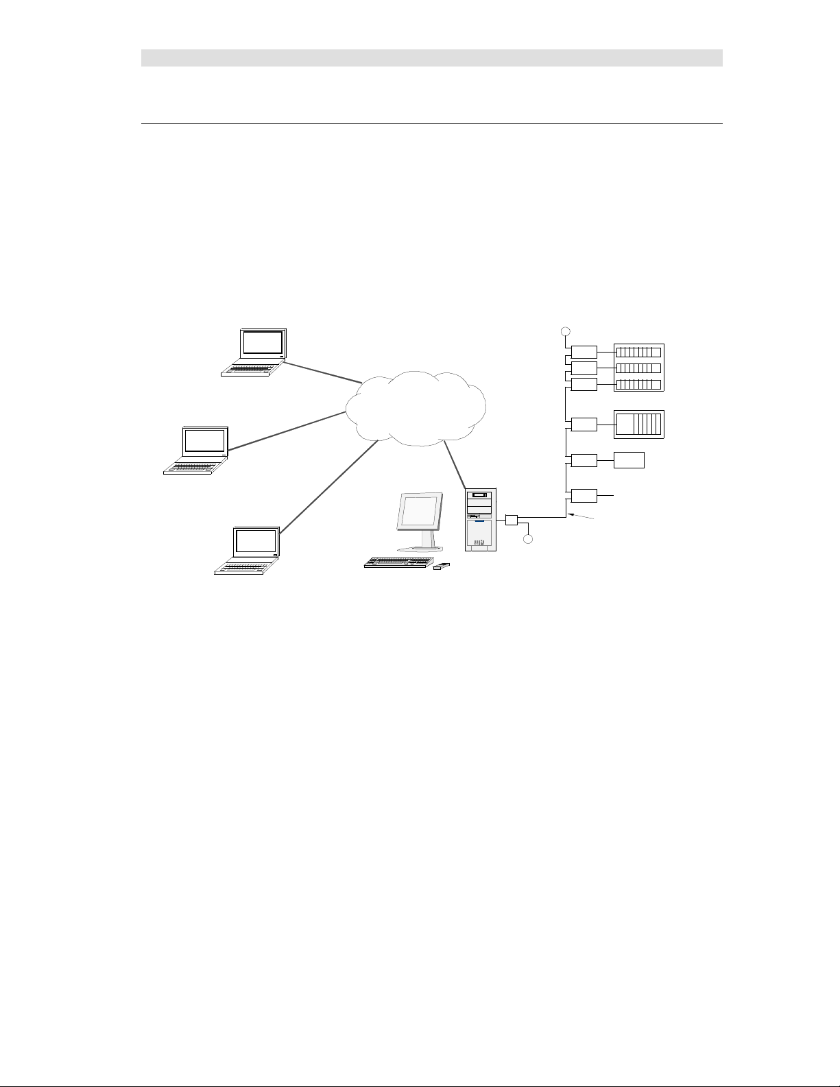
A typical MCN Server is shown in the figure below attached to an MCN network. The MCN ClientServer Remote Comparator Display system consists of:
An MCN Server PC running MCN the Server program
One or more network interfaces for the MCN Server PC (such as a HIB-IP, internal PCLTA or
HIB-232)
One or more Comparator I/O Modules (such as an AIB or CIB)
Optionally, other interface modules (such as IOB) to drive auxiliary outputs and alarms
Client PCs connected to the PC over an IP LAN or WAN.
MCN CLIENT PCs
IP WAN
MCN
SERVER
WITH INTERNAL
PCLTA CARD
T
T
COMPARATORS
CIB
CIB
CIB
AIB
IOB
ALARMS
CIB
Local MCN Network
CA-80705-100
ASTROTAC
RYB-8
RELAY
Figure 1 - Simple MCN Client-Server System
The main programs that make up the MCN Client-Server software package:
MCNConfig Program
(McnConfig Server.EXE)
This is the configuration program run by an engineer or technician to build the configuration files
when the system is installed or changed.
MCN Server Program
(McnRcd Server.EXE or McnRcd Advanced Server.exe)
This is the program that runs on the MCN Server PC. It has a local display that displays the status
of the devices on the MCN system (Comparators, I/O points, alarms, etc.). It allows the operator
to control receivers (with Force-Vote and Disable functions) and other I/O devices (relays, etc.)
from the MCN Server PC.
The MCN Server program also passes the status and control data to MCN Client PCs over an IP
LAN or WAN.
MCN Client Program
(ClientRCD.exe)
HIThis is Client program that runs on remote PCs to display the status of and control the MCN
system. The MCN Client program runs on PCs connected to the MCN Server over an IP network,
and thus do not need their own MCN Network Interface.
1
2
3
GENERAL
PURPOSE
OUTPUTS
10 68-11824-210
Page 11

Introduction
Reference Documents
Details of other hardware components of the system can be found in the following documents:
Monitoring and Control Network, System Manual
Part Number S2-60425
HIB-IP Remote Network Interface Hardware Reference Manual
Part Number S2-61173
HIB-232 Host Computer Interface Module, Hardware Reference Manual
Part Number S2-60427
CIB Comparator I/O Module, Hardware Reference Manual
Part Number S2-60426
AIB Astro-TAC Comparator Interface Module, Hardware Reference Manual
Part Number S2-60399
IOB I/O Control Module, Hardware Reference Manual
Part Number S2-60630
EXB-232 and EXB-IM Network Extender Modules, Hardware Reference Manual
Part Number S2-60596
EXB-IP and EXB-FI Network Extender Modules, Hardware Reference Manual
Part Number S2-61089
Router Modules, Hardware Reference Manual
Part Number S2-60649
Network Interfaces & Drivers
Three general categories of MCN Network Interfaces are used with MCN Server program:
HIB-IP External Modules For connection to MCN networks over IP networks
HIB-232 External Modules For Local RS-232 connection
(Although the HIB-232 manual talks about dial-up operation,
the MCN Server program is intended to be connected full-time
to the MCN network(s) that it serves. It does not support dialup operation of the HIB-232.)
Internal Boards PCLTA-21 For direct connection to the MCN Network
(Also support connection to remote networks using EXB
Network Extender Modules)
11 68-11824-210
Page 12

Introduction
Supported Network Interfaces
The MCN Server program can use the following versions of HIB modules or the PCLTA cards for the
interface between the PC and the MCN network.
HIB-IP Modules Version 110 & up 78K
HIB-232 Modules Version 200 & up 78K (with Rotary address switches on back)
PCLTA-21 Boards Half-Size PCI boards 78K or 1250 versions
Unsupported Network Interfaces
The following older Network Interfaces are not supported with MCN Server
HIB Modules Version 000-199 (without Rotary address switches on back)
PCLTA (original) Full-size ISA bus boards 78K or 1250 versions
Single or dual interfaces
PCLTA-10 Half-size ISA bus boards 78K or 1250 versions
PCLTA-20 Half-size PCI bus boards 78K or 1250 versions
All HIB-232 modules have a unit number of S2-60081-xxx. If the ‘xxx’ number is less than 200 you
have an early version HIB module that is not supported..
Drivers for MCN Server
The PCLTA Interface boards need a software driver to run the MCN Server program.
This will be included with the PCLTA & software package.
The HIB-IP and HIB-232 modules do not need a driver for normal operation of the MCN Server
program.
12 68-11824-210
Page 13

Introduction
PC Hardware Requirements
MCN Server software requires a PC with the following minimum system configuration:
Windows 2000, XP, or Server 2003
Pentium 4, 2GHz or above
512MB Memory
Color Monitor with at least 800 x 600 resolution, higher resolution recommended
Mouse
100Base-T Ethernet port
One open serial port if the local network interface is a HIB-232
One open PCI slot if the network interface is a PCLTA
CD ROM Drive
3.5” Floppy Drive
Open USB Port
For MCN Client PCs, requirements are similar to above:
Win 2000, XP, or Server 2003
Pentium 4, 2GHz or above
512MB Memory
Color Monitor with at least 800 x 600 resolution, higher resolution recommended
Mouse
100Base-T Ethernet port
CD ROM Drive
13 68-11824-210
Page 14

Installation
Installation Overview
The installation of the MCN Server software and network interfaces are done in the following order:
1) If PCLTA network interface will be used, install the PCLTA device drivers and network interface
card, then test the interface. See PCLTA Network Interface Installation (If needed) below.
2) Run setup.exe on the MCN Server PC to install the MCN Server software. See Installing MCN
Server Software on page 20 in this section.
3) Run the MCNConfig program to customize the MCN System Resources and display windows for
your system.. See MCNConfig Program on page 37.
4) If you are using HIB-IP units, program them using MCNConfig program. See Programming HIB-
IP Units on page 52.
5) Install the Security Hardware Key in a USB slot on the MCN Server PC.
6) Run the MCN Server program on the MCN Server PC. See MCN Server Program on page 136.
You will be asked to enter the MCN Software Key and IP parameters on the first use.
7) Run setup.exe on the MCN Client PCs to install the MCN Client program. See Installing MCN
Client on page 33 for details.
8) Run the MCN Client program on the Client PC(s). See MCN Client Program on page 151.
14 68-11824-210
Page 15
Installation
PCLTA Network Interface Installation (If needed)
Install PCLTA Device Drivers
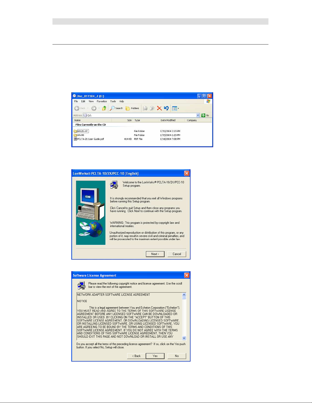
Insert the PCLTA driver CD into the CDROM drive. When the CD contents folder is displayed as
shown below, double-click on the “Win2K-XP” folder. (Windows 98 is not a supported operating
system for MCN Server.) Then double-click on the setup.exe file to start the installation for PCLTA
device drivers.
The PCLTA Install welcome screen will be displayed as shown below. Before continuing, it is
recommended that you exit all Windows programs.
Click on the Next button to display the “Software License Agreement” window as shown below.
15 68-11824-210
Page 16
Installation
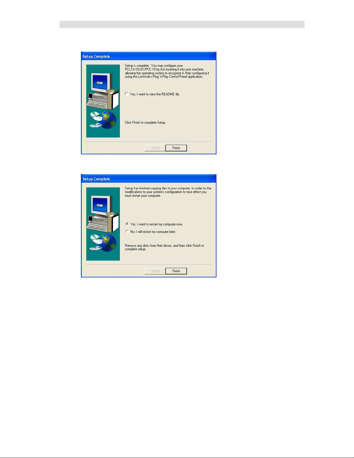
Click on the Yes button to display the “Setup Complete” window as shown below.
Click on the Finish button. The following window will provide a selection for restarting the computer.
Select “NO, I will restart my computer later”, then click the Finish button.
During the PCLTA device driver installation, the following line is added to the config.nt file to provide
a driver for DOS applications:
device=%SystemRoot%\system32\pcltdos.sys /D1
Finally, power down the computer so that the PCLTA network interface card can be installed.
Install PCLTA Network Interface Card
The PCLTA device drivers must be installed prior to installing the card. If the drivers have not been
installed, complete the previous step.
To install a PCLTA card into your PC, follow these steps:
1. Turn off the PC and remove the power cord.
2. Open the PC case and locate an empty slot.
3. Remove the corresponding blank panel from the rear of the PC.
4. Insert the PCLTA card into the slot, ensuring that the edge connectors are fully mated, and the
slot in the rear panel-mounting lug of the PCLTA is aligned with the threaded hole in the PC
chassis.
5. Replace the screw to hold the PCLTA firmly in place.
16 68-11824-210
Page 17
Installation
6. Reinsert the power cord and then restart the PC.
On power-up, Windows will automatically sense the Plug-n-Play adapter, and associate it with the
drivers installed in the previous step.
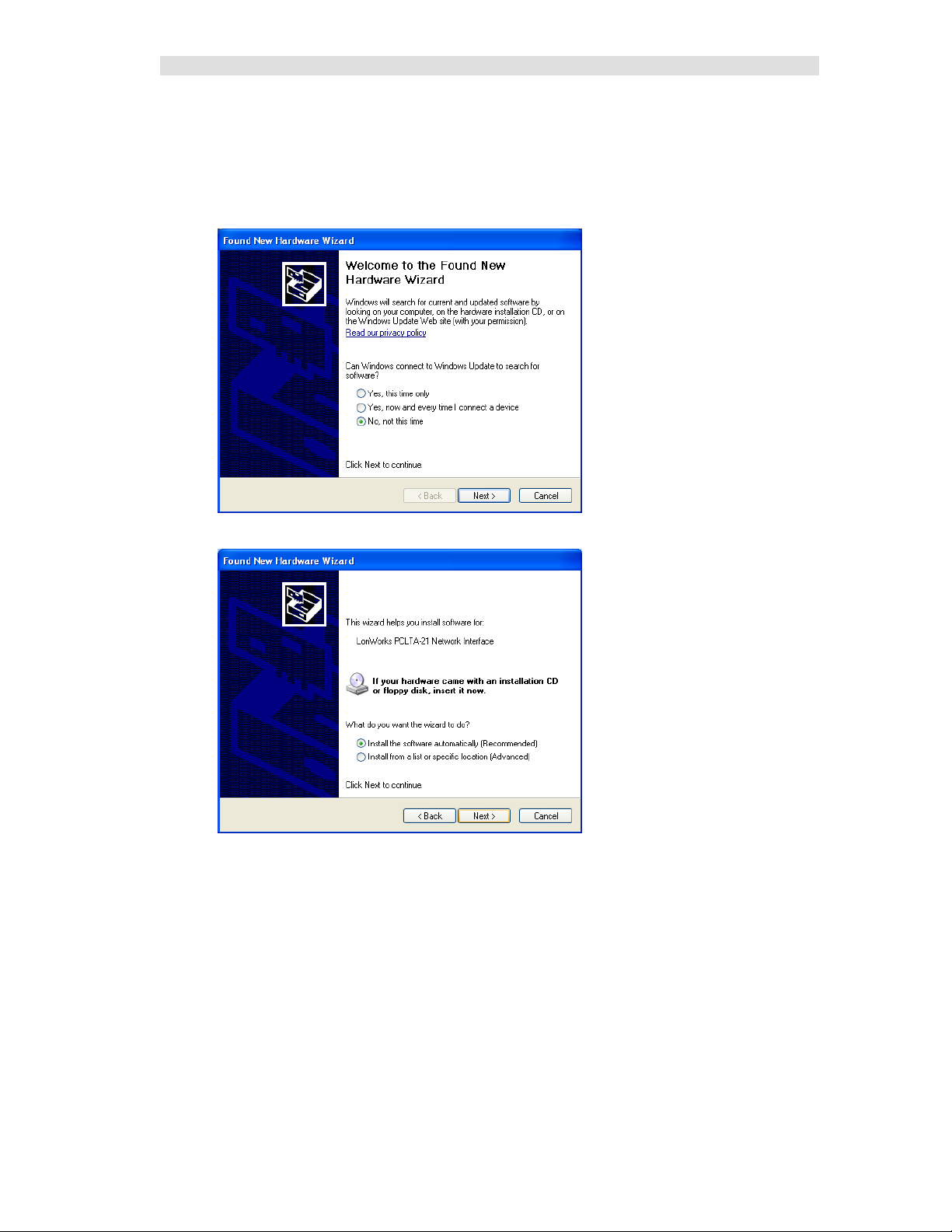
If the Plug ‘n Play features of the card failed, the following “Found New Hardware Wizard” window
may be displayed.
Select “No, not this time”, then click the Next button to display the following window.
On the above window, select “Install the software automatically”, then click the Next button. Click on
the Next or Finish buttons in the remaining windows to complete the installation.
17 68-11824-210
Page 18
Installation
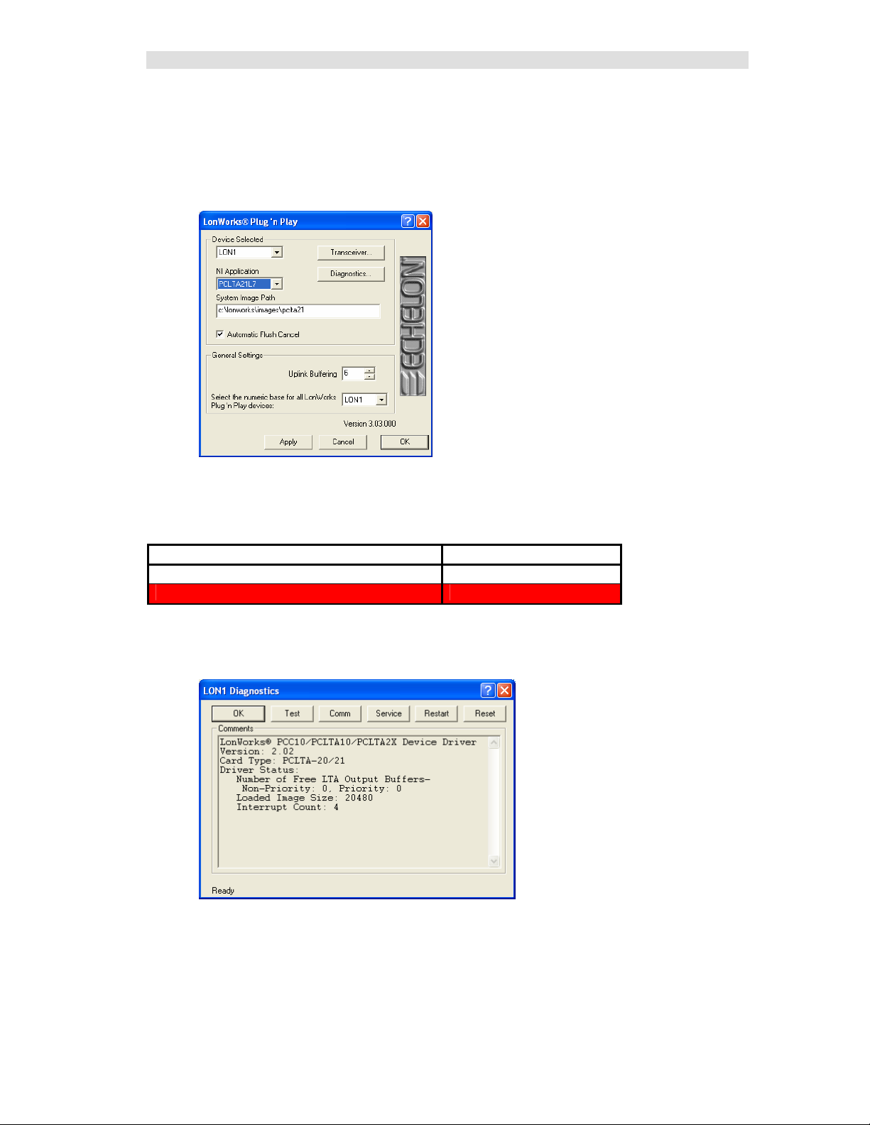
Configure and Test the PCLTA Network Interface
From the Start menu button on the Windows desktop, select Control Panel from the list, then double
click the “LonWorks Plug ‘n Play” icon. (If the “LonWorks Plug ‘n Play” icon is not visible, change the
Control Panel properties to “Classic View”.)
The following “LonWorks Plug ‘n Play” window will be displayed.
In the NI Application drop-down list, choose an image that is compatible with the MCN Server program
from the following table. (For all operating systems, the Image name should end with “L7”.) Then click
the Apply button.
Windows XP, 2000, or 2003
Images Compatible with MCN Server program PCLTA21L7
Images that will not work PCLTA21VNI, PCL10VNI
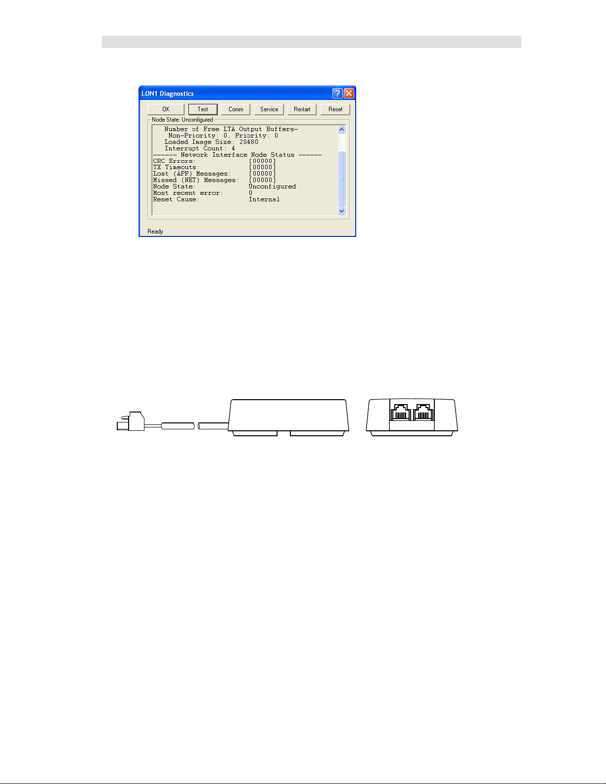
To check if the PCLTA network interface has been installed correctly, click the Diagnostics button to
display the following window.
18 68-11824-210
Page 19
Installation
Finally, click the Test button to display status information similar to the following window.
When finished, click the OK button on this “LON1 Diagnostics” window, then click the OK button on
the “LonWorks Plug ‘n Play” window.
If the PCLTA network interface card was installed prior to device driver installation, the PCLTA may
not function correctly. To correct this situation, see Error! Reference source not found. on Page Error!
Bookmark not defined..
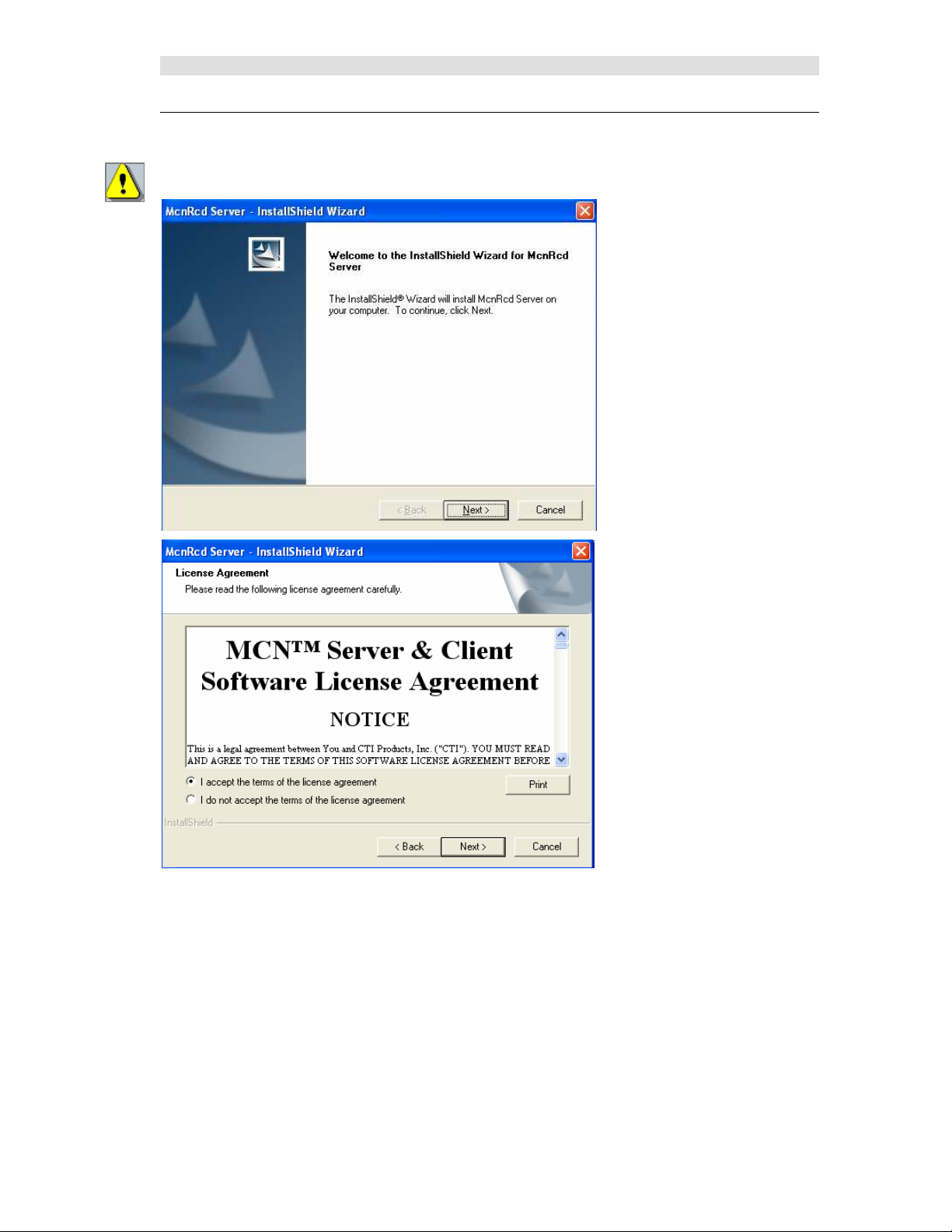
Cabling and Termination
The PCLTA card is different from all other MCN modules in that it does not have an RJ-45 connector
for the network cable to plug into. A ‘T’ Adapter (S2-60617), shown below, must be installed to
connect the PCLTA’s two-pin connector with the MCN network cable. Use one RJ-45 connector on this
adapter for the network cable, and plug a terminator (either TP/XF1250 or TP/FT10) into the other.
CABLE
CA-80273-101
19 68-11824-210
Page 20
Installation
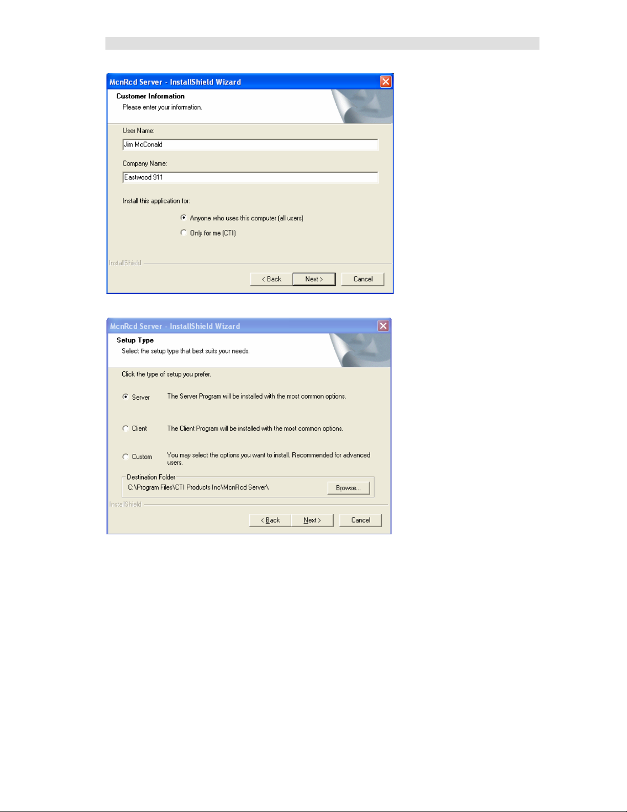
Installing MCN Server Software
Run Setup.exe from the CD.
You must have Administrator rights to install the MCN Server software.
20 68-11824-210
Page 21
Installation
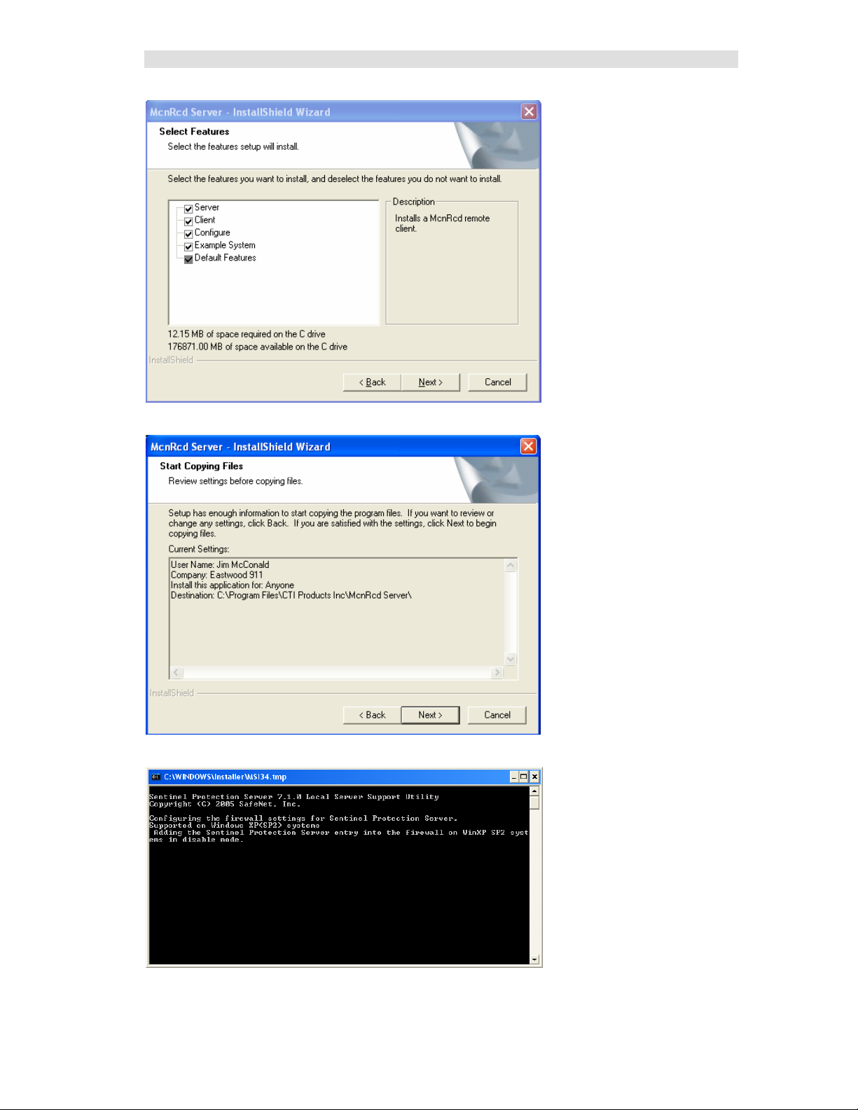
If you choose the custom installation, you can install both the MCN Server and the MCN Client
programs on your PC.
21 68-11824-210
Page 22
Installation
But we won't do that here…
22 68-11824-210
Page 23
Installation
23 68-11824-210
Page 24
Installation
Hardware Setup – HWSetup.exe
The Hardware Setup program is used to select and set up the Network Interface (PCLTA, Non-Dial-up
HIB-232, or HIB-IP) to use in the system.
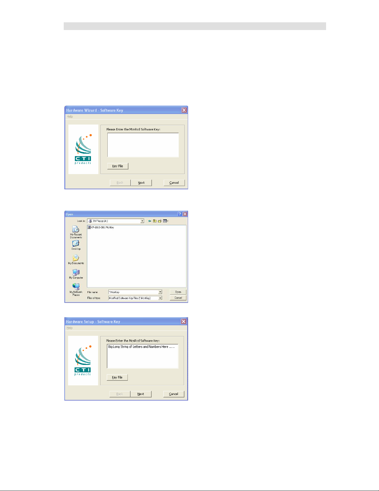
Software Key
You will be asked to enter your software key.
You can type it in if you want to, but it's easier to hit the Key File button and find your key file. Your
software key file will be included on a custom diskette or CD for your system.
Navigate to find the software key file and click Open.
The Software Key will be entered. Click the Next key.
24 68-11824-210
Page 25
Installation
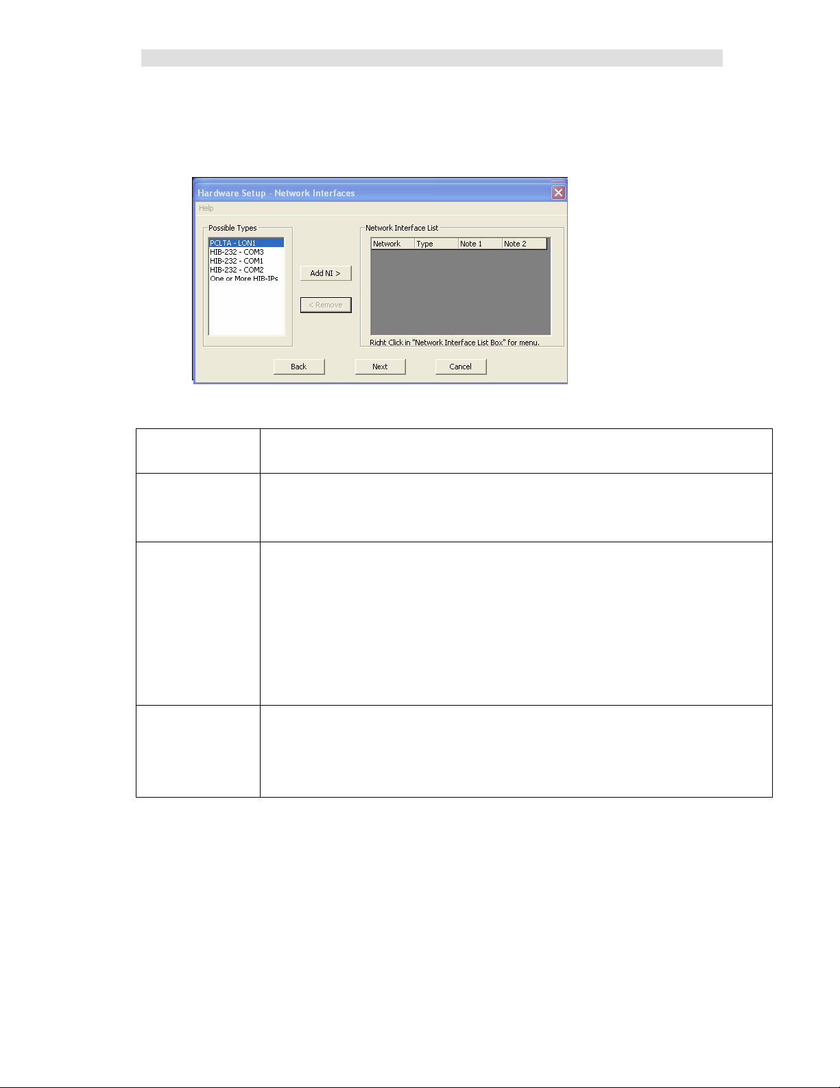
HW Setup - Network Interface Setup
The first time HWSetup is run, it sees that there is no Network Interface defined on the PC. It will ask
you what type of Network Interface (NI) you plan to use.
The Standard version of MCN server allows the selection of just one Network Interface from this
window. The Advanced version allows the selection of multiple Network Interfaces.
Network Interface
Type
PCLTA Internal board in the PC. The MCN network will connect directly to this board.
HIB-232 - COMx Non-Dial-up HIB-232 units
HIB-IP Remote Network Interface that connects to the PC through an IP channel
Description
If there is a PCLTA board that is properly installed, the HW Setup program will list it in
the "Possible Types" list. See: HW Setup - PCLTA Setup
- Non-dial-up HIB-232s connect to a COM port directly
or through external leased-line modems or equivalent.
- The program detects all COM ports reported by Windows.
Not all may be available for use, depending on your PC.
Some COM ports may not be brought out to a connector.
Some COM ports may actually be used for an internal modem.
(In the example above, COM3 is actually an internal modem.)
See HW Setup – HIB-232 (non dial-up)
You will set up parameters for the HIB-IP unit in the system database by using
McnConfig program. (You will also have to download those settings to the HIB-IP from
the McnConfig program.)
25 68-11824-210
Page 26
Installation
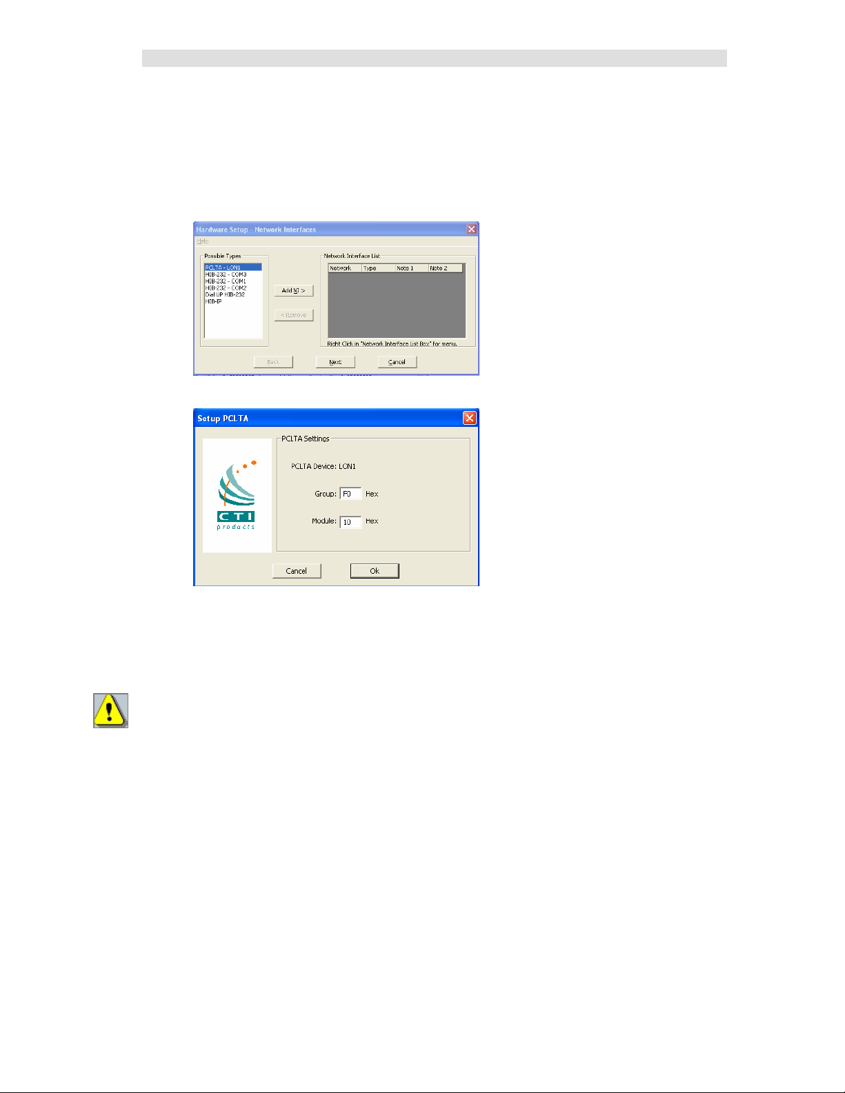
HW Setup - PCLTA Setup
If a PCLTA board (and its driver) is properly installed in your PC, the HW Setup program will detect it
and present it in the Possible Types list box.
In the unlikely event that you have multiple PCLTA boards installed in your PC, you can select one of
them to use. The MCN Standard Server program supports only one Network interface at a time.
• Select the PCLTA and click the Add NI button.
The Group/Module address defaults to “F0/10” during installation.
• Change the Group and Module address as required for your system.
• Click the OK button.
Important: MCN Address Setting
Each PC and each MCN module in the system must have a unique address. If you are setting up
multiple PCs, be sure to set up each PCLTA card with its own address.
If you have a Custom Engineered System (with custom system documentation part number
KA-8xxxx-xxx), be sure to set the PCLTA address to the Group & Module numbers shown in your
documentation. Failure to do so may cause the system not to work
• In the above window, click the OK button.
26 68-11824-210
Page 27
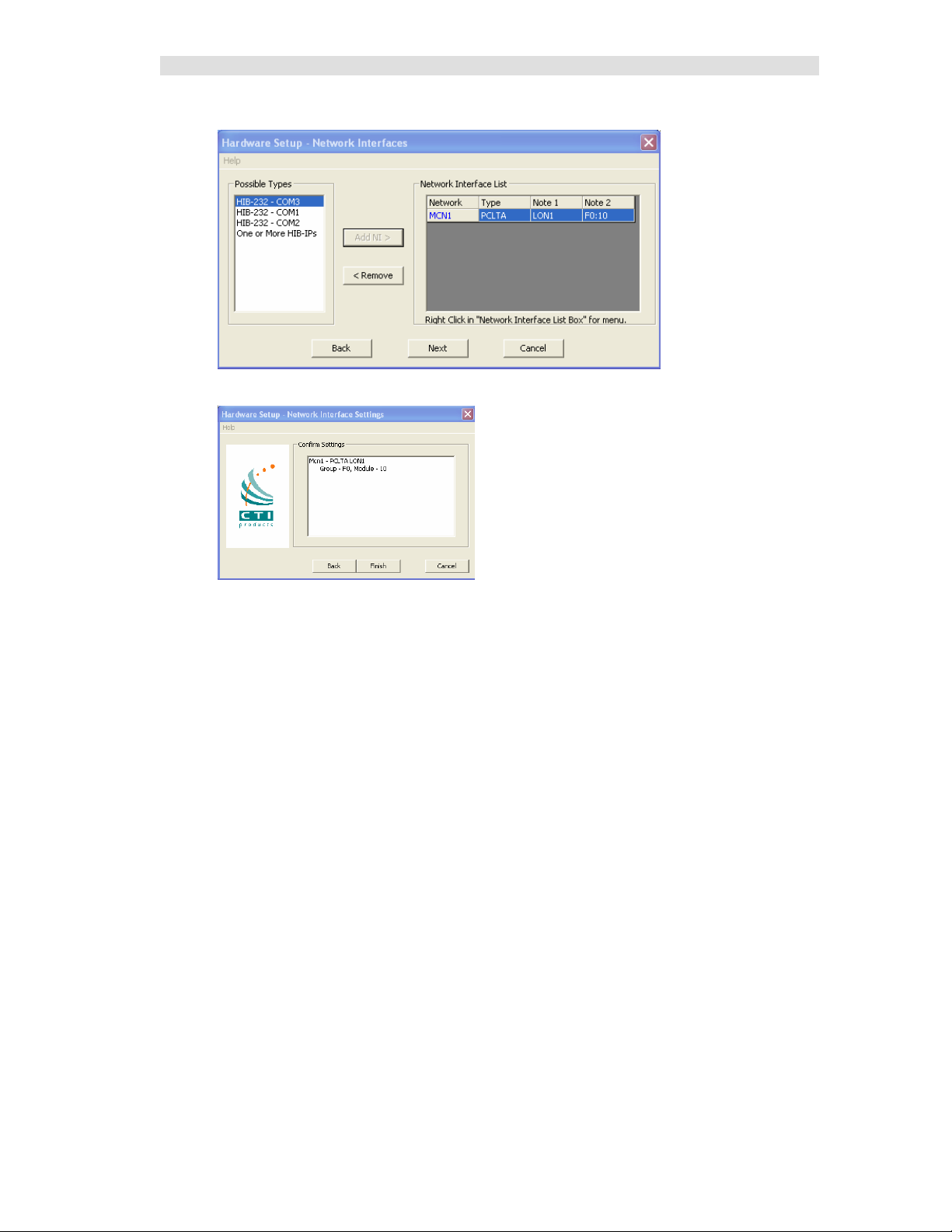
Installation
The Network Interface window will re-appear:
• Click the Next button.
• Press the Finish button in the confirmation window.
The appropriate information for the PCLTA is now stored in the registry and will be available for use by
McnConfig and MCN Server programs.
The MCN Group and Module addresses are set up on hex rotary switches on the back of the HIB-232
unit.
27 68-11824-210
Page 28
Installation
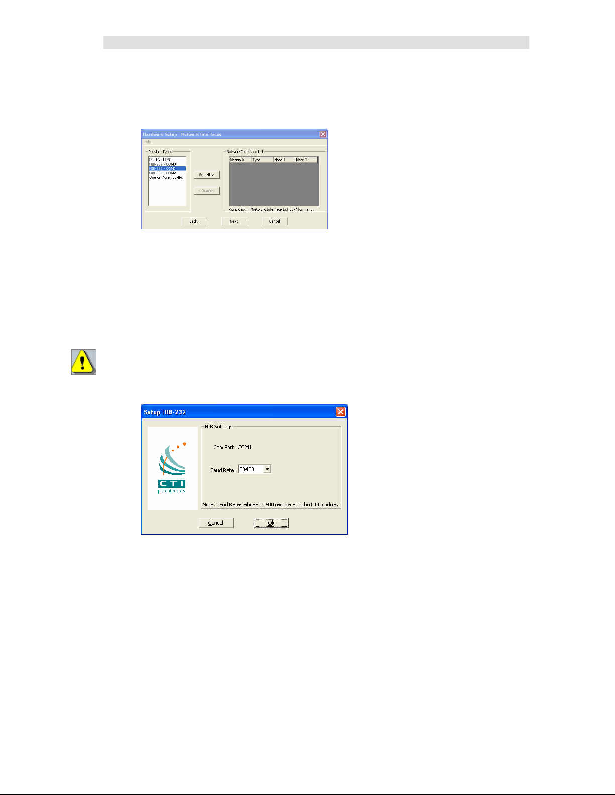
HW Setup – HIB-232 (non dial-up)
If you have a HIB-232 module (and are using it directly connected or through leased line modems) select
the proper COM port from the Possible Types list box:
The program detects all COM ports reported by Windows.
Not all may be available for use, depending on your PC.
Some COM ports may not be brought out to a connector.
Some COM ports may actually be used for an internal modem.
(In the example above, COM3 is actually an internal modem.)
USB to Serial Adapters
The MCN Server program will work with some USB to Serial adapters. We cannot guarantee that it will
work with all such adapters since we cannot test all brands.
Some USB to Serial adapters will change their COM port number when they are plugged into a different
USB connector. If you are using one of these and you change its connection, you will have to re-run the
HW Setup program to select the new COM port.
• Select the proper COM Port and Click the Add NI button
• Select the appropriate baud rate. Be sure that the baud rate matches the Baud rate switches on
the HIB-232 module.
(The Group and Module addresses for the HIB-232 unit are set with rotary switches
on the unit. See Important: MCN Address Setting on Page 26 for more information on MCN
addressing. )
• Click the OK button.
28 68-11824-210
Page 29
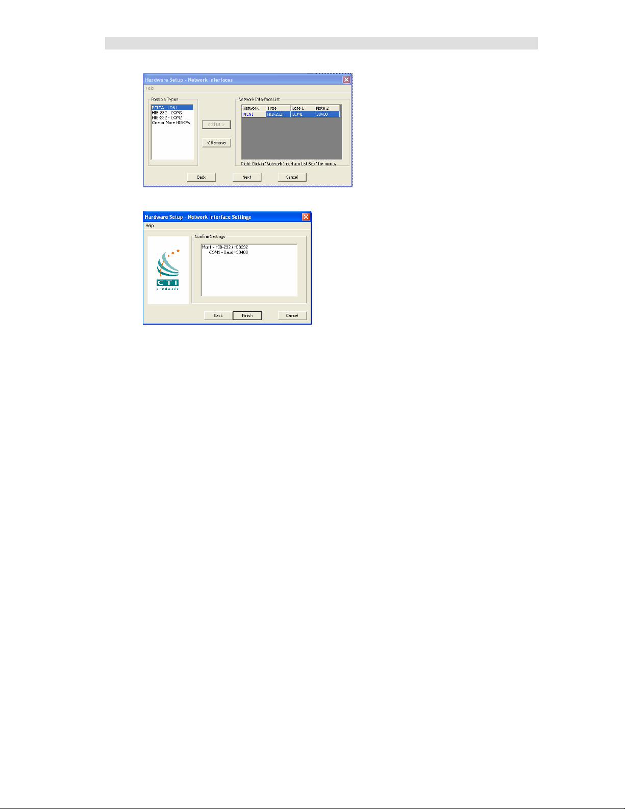
Installation
• Click the Next button
• And hit the Finish button.
The HW Setup program will save the setting in the registry.
This setting will be used by the MCN Server program.
29 68-11824-210
Page 30
Installation
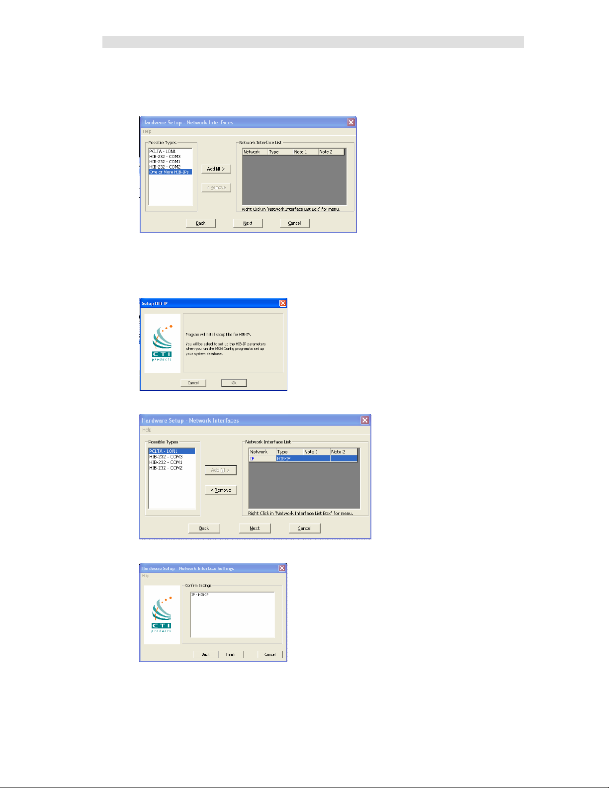
HW Setup – HIB-IP
If you will be using a HIB-IP unit, select it from the Possible Types list.
• Select the HIB-IP option. (Although the line says "One or more HIB-IPs", you will be able to
use only one HIB-IP with the standard MCN Server program. If you need to connect to
multiple HIB-IP units at a time, you'll need the MCN Advanced Server software.
• Click the Add NI button.
• Click the OK button.
• Click the Next button
• Click the Finish button.
30 68-11824-210
Page 31

Installation
HIB-IP Parameters
As shown in the “Setup HIB-IP” window above, you will later enter the HIB-IP parameters in the
system database using the McnConfig program. You will also have to download those parameters to the
HIB-IP using McnConfig.
Miscellaneous Installation Considerations
Changing Settings for your Network Interface
If you need to change the settings for your Network interface, re-run the HWSetup program. This
program can be used to change the:
• Type of Network Interface
• PCLTA Device or Group & Module address
• HIB-232 COM Port or Baud Rate
To change these items you can either:
• Double click on the Network Interface to edit its parameters or
• Click the Remove button to remove the Network Interface and select a different one.
If you have a Custom Engineered System (with custom system documentation part number KA-8xxxxxxx), be sure to set the PCLTA address to the Group & Module numbers shown in your documentation.
Failure to do so may cause the system not to work
In the above window, click the Next button
PC Power Options Setup
The “Power Options” icon in the Control Panel allows for a wide variety of PC operation parameters.
However, installation of MCN Server software will disable any possibility of the PC going into a
standby or hibernate condition.
The monitor may be allowed to “sleep” as long as the “Monitor Timeout” is less than the “Standby
Time”. Otherwise, the monitor will never sleep.
Printer Installation
For printer logging to occur, a printer must be installed from the Windows operating system. From the
Start menu button on the windows desktop, select “Printers and Faxes” from the list, then select “Add a
Printer” from the list of “Printer Tasks”.
31 68-11824-210
Page 32

Installation
Changing the PCLTA Group/Module Address
If the Group/Module address for the PCLTA Network Interface needs to be changed (or to query the
PCLTA for its current address), simply run the hwsetup.exe program. This program can be found in the
main program working directory (typically c:\Program Files\CTI Products Inc\McnRcd). Then click the
Next button until the following window is displayed.
The Group/Module address defaults to “F0/00” during installation. However, each PC must have a
unique address.
In the above window, click the Next button, then the Finish button to complete the address change for
the PCLTA Network Interface.
Uninstalling MCN Server Software
To uninstall MCN Server software, insert the MCN Server distribution CD into the CDROM drive.
Click the Start menu button on the Windows desktop, then select “Run …” from the list. In the “Run”
dialog box, type d:setup.exe (where d is the drive letter of the CDROM drive), then click the OK button.
In the “InstallShield Wizard” window, select “Remove”, then click the Next button. Follow the prompts
until the InstallShield Wizard completes the uninstallation.
32 68-11824-210
Page 33

Installing MCN Client Program
You would normally install the MCN Client program on a separate PC from the MCN Server, but you
can also install a copy on the MCN Server PC.
You must have Administrator rights to install the MCN Client program.
The installation steps are shown below.
33 68-11824-210
Page 34

Installation
Enter your user information.
Select the “Setup Type” as “Client”.
34 68-11824-210
Page 35

Installation
After you confirm everything is in order, hit Next.
The Installshield program will install the files.
35 68-11824-210
Page 36

Installation
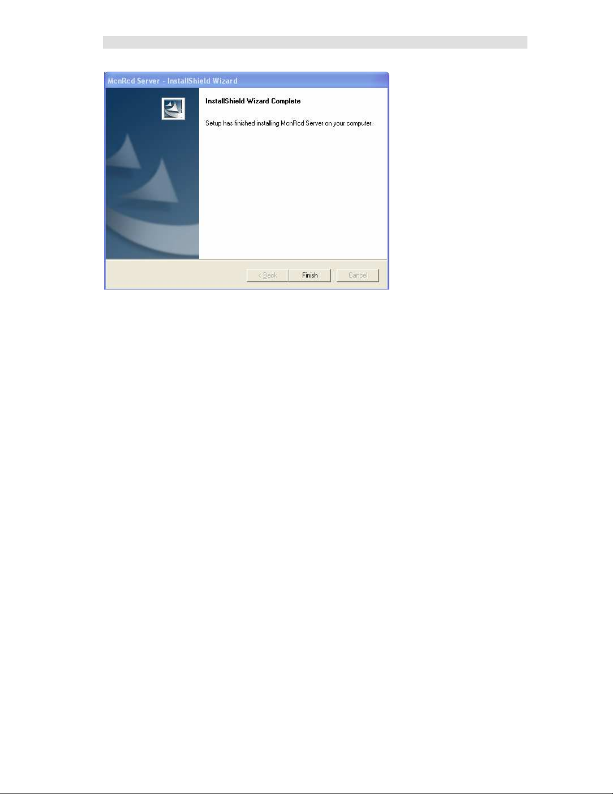
Click the Finish button to finish.
36 68-11824-210
Page 37

MCNConfig Program (MCNConfig Server.exe)
The MCNConfig program is used to configure an MCN system. System configuration involves:
1. Defining system resources in the Resource Windows, such as Network Interfaces, Hardware
Modules, Receiver Names, Channels, and Email Groups.
2. Designing the Display Windows to be displayed for the MCN Server and MCN Client
programs.
Resource Windows
The MCNConfig program will be used to define your system by entering data into the following
Resource Windows. (There is only one of each type of Resource Window for each system.)
Network Interface Indicates which Network Interface is used for this system.
If you are using a HIB-IP unit, this is where you will enter the
IP and MCN address settings.
Hardware Enter the information about the hardware modules
(CIBs, AIBs, IOBs, etc.) present in the system.
Receivers Enter the site Names and Descriptions for all the receivers in the system.
Channels Enter the names of the radio channels used in the system. Each channel can
have multiple hardware modules.
Email Groups Enter the Email Groups & Recipients for alerts generated by the MCN
Server program.
Display Tables Each type of device to be monitored and controlled will have a Display
Table. The Display Table maps the hardware I/O bits of the device into
status indications. The MCN Server software ships with the standard
Comparator Display Table and a number of generic I/O Display Tables. A
future release of the software will make it possible to create customized
status text displays (On/Off, Alarm,, Run/Normal, etc.) for any special
control and monitoring devices in your system.
Certain fields of the resource windows link to each other as shown by the arrows.
37 68-11824-210
Page 38

MCNConfig Program
Display Windows
Display Windows are the status screens that you build for the MCN Server and Client programs. Each
Display Window can contain multiple Tabs and multiple channels. Multiple Display Windows can be
defined for a system.
Typical Technician Display Window
Some examples of Display Windows that can be defined are:
For Technicians, a large display grid with one tab showing all systems on a single grid.
For Dispatchers, a small grid with multiple tabs showing only one channel per tab.
Different Display Windows for different dispatchers with different subsets of channels available.
(Police channels for Police dispatcher, Fire & EMS channels for Fire Dispatcher, etc.)
Typical Dispatcher Display Window
Example System
You can load the Example System from the “Example System” directory off the main program directory
(typically c:\Program Files\CTI Products Inc\McnRcd\Example System).
38 68-11824-210
Page 39

MCNConfig Program: Getting Around
Menu
Min / Max /
Close
Toolbars
Status
The MCNConfig program is a 32-Bit Windows program. Navigation, menus and toolbars are similar to
other Windows programs.
Standard Windows Hot-Keys that can be used with this program include:
Ctrl-C Copy current selection to clipboard
Ctrl-V Paste clipboard to current location in selected window.
Context Sensitive Menus are available in different windows by Right-clicking an item.
Scroll Bars are available when the contents of a window (other than the main window) are
larger than the size of that window.
Controlling the Windows
You can have multiple windows (resource windows or display windows) open on the workspace at a
given time. You can control the windows as follows:
View the Resource Windows (Hardware, Receivers, Channels, Display Tables or Email Groups)
or Display Windows with the View menu.
Select an open window by clicking the mouse on it or using the Window menu.
Move a window by grabbing its title bar and dragging it.
Re-size a window by grabbing an edge or corner and dragging it.
Minimize /Restore, Maximize and Close the window using the standard Windows buttons on
the top right corner of each window. If you close the last window, you will
close the system. If changes have been made, you will have a chance to
save the system.
You can save the sizing and layout of your workspace by using the Save Layout command in the
Edit menu.
Screen Elements
Title Bar
39 68-11824-210
Page 40

MCNConfig Program: Getting Around
This program has many standard menu functions that are used in other Windows programs. For
example, menus can be selected with the mouse or by holding down the ALT key while pressing the
underlined letter on the menu. Note that a menu’s appearance may change, and various menu options
may be disabled, depending on the current state of the system.
Menu Bar
Two versions of the Menu Bar will be displayed. When there is no system opened, a small Initial Menu
Bar will be displayed:
When a system is loaded, the standard Menu Bar will be displayed:
Initial File Menu
When there is no system loaded, the Initial File Menu is available.
New Starts a new system from scratch.
Open Opens an existing system from disk. This will open all the
files associated with a particular system. Only one system
can be open at a given time. You must close the existing
system before starting a new system, importing a system
from the DOS version of MCNRCD , or opening another
system.
Import Imports a system from the DOS version of the MCNRCD
program.
Recent Files Allows you to quickly open a recently used system.
COM Port Selects the COM port used to program HIB-IP units
Exit Exits the program.
40 68-11824-210
Page 41

MCNConfig Program: Getting Around
Standard File Menu
Once a system is loaded, the Standard File Menu is available:
Close Closes the current system.
Save Saves the current system with the current name.
Save As Saves the current system with a new name.
Print Prints the contents of the currently selected window.
COM Port Selects the COM port used to program HIB-IP units
Exit Exits the program. If something has changed, you will be
The Standard File Menu does not have the Open, Import, or Recent Files menu items.
If something has changed, you will be given a chance to
save it.
This will save all the files associated with a particular
system.
This will save all the files associated with a particular
system.
given a chance to save it.
Saving Files
We recommend that you save the system in a subdirectory or sub-folder of the main program working
directory (typically C:\Program Files\CTI Products Inc\McnRcd Standard). When you first save a
system, Windows may default to the My Documents folder. If so, browse to the working directory and
add a new directory for your system description files.
Edit Menu
The Edit Menu is available whenever a system is loaded. Some menu items may or may not be enabled,
depending on what is currently selected.
Cut Cuts the selected item(s) and saves a copy in the clipboard.
Copy Copies the selected item(s) to the clipboard.
41 68-11824-210
Page 42

MCNConfig Program: Getting Around
Paste Pastes the contents of the clipboard to the current cursor
Save Layout Saves the working screen layout (Window Positions,
New Display Window Opens a new MCN Display Window.
Delete Display Window Deletes an MCN Display Window.
Display Window Properties Sets the properties (Window Title, Number of Rows &
Email Group Properties Sets the properties (Group Name, Holdoff Time) for the
Display Font Sets the font and size for the currently selected Display
location. Some fields are special fields and will only accept
certain data (or certain ranges of data) from the clipboard.
See Restrictions on Using the Clipboard on page 90 for
more details.
Column widths) for use when you start the program the
next time.
Columns) for the currently selected MCN Display
Window.
currently selected Email Group.
Window. This is used to simulate the display for the MCN
Server program. However, these font settings are used only
for the MCNConfig program. The font settings for the
MCN Server program (and the MCN Client program) are
set by the user from those programs.
View Menu
Toolbars Turns the Toolbars on or off.
Status Bar Turns the Status Bar (at the bottom of the screen) on or off.
Network Interface Opens the Network Interface Window and makes it active.
Hardware Opens the Hardware Resource Window and makes it active
Receivers Opens the Receiver Resource Window and makes it active.
Channels Opens the Channel Resource Window and makes it active.
Email Groups Opens the Email Groups Window and makes it active.
Display Window Opens an RCD (Remote Comparator Display) Display
Display Tables Opens the Display Tables Window and makes it active.
Layout Mode Turns on Layout Mode in a Display Window to enable re-
Window and makes it active.
sizing of columns (active only when a Display Window is
active.)
42 68-11824-210
Page 43

MCNConfig Program: Getting Around
Window Menu
Cascade Cascades all open windows
Tile Tiles all open windows
Window List (1-N) Indicates currently open windows. Use this list to select a
Resource (Network Interface, Hardware, Receivers,
Channels, Email Groups, and Display Table) or Display
window. The Resource Windows will appear in the order
they were opened.
Display Windows will be listed as named by the user.
(Windows 6 & 7 in this screen shot are Display Windows.)
Help Menu
Help Topics Brings up the standard Help menu.
About MCNConfig Displays information about the program
43 68-11824-210
Page 44

MCNConfig Program: Getting Around
File
Toolbar
Add Resource
Display & Help Toolbar
Toolbars
The MCNConfig program has dockable toolbars indicated in the screen capture below. You can move
the toolbars by clicking on the beginning or ending line in the toolbar and dragging it to the desired
location.
Toolbar
Each Toolbar button has a Tool Tip that will be displayed when you hover the mouse over it. A more
lengthy description of the button will appear in the Status Line at the bottom of the main window.
Edit Toolbar
File Toolbar
New Opens a new system.
Same as File … New menu item.
Open Opens a system from disk.
Same as File … Open menu item.
Save Saves the current system to disk.
Same as File … Save menu item.
Print Prints the data from the active window.
Same as File … Print menu item.
44 68-11824-210
Page 45

MCNConfig Program: Getting Around
Add Resource Toolbar
New Network Interface Module
Adds a new Network Interface module to the Network
Interface resource window. (The Standard version of the
MCN Server program supports only 1 Network Interface.
If you need to support more than one Network Interface,
you will need the MCN Advanced Server software.)
New Module Adds a new module to the Hardware List resource window.
Adds the appropriate number of Receivers or I/O Blocks in
the Receiver window.
New Channel Adds a new channel to the Channel List resource window.
New Email Group
Adds a new Email Group (tab) to the Email Group resource
window.
New Email Recipient
Adds a new Email Recipient to the currently selected Email
Group. If no Email Group is defined, this will add a new
Email Group.
Edit Toolbar
Items in the Edit Toolbar work only in the currently selected window. If a toolbar item is not available
in a particular window, it will be grayed out.
Append Adds a new item to the end of a list of items. This item is
not available in the Receiver Window or Display Window.
Insert Inserts a new item at the current location in a list of items.
This item is not available in the Receiver Window or
Display Window.
Delete Deletes the currently selected item(s).
Cut Deletes the currently selected item(s) and copies them to
the clipboard.
Copy Copies the currently selected item(s) to the clipboard
without deleting them from the selected window.
Paste Pastes the clipboard contents to the current location in the
selected window:
Some fields are special fields and will only accept certain
45 68-11824-210
Page 46

MCNConfig Program: Getting Around
data (or certain ranges of data) from the clipboard. See
Restrictions on Using the Clipboard on page 90 for more
details.
Move Up Moves up the currently selected item in the list. This item
is not available in the Receiver Window or Display
Window.
Move Down Moves down the currently selected item in the list. This
item is not available in the Receiver Window or Display
Window.
Sort Numeric Sorts the Hardware Module list by MCN Group & Module
numbers. This item is available only in the Hardware
Window.
Sort Alpha Sorts the list alphabetically. This item is available only in
the Channel Window and the Email Window.
Display & Help Toolbar
New Display Adds a new display window.
Display Window Properties
Opens the Grid Properties dialog box. Allows changes to be
made to the window Title, and the number of rows and
columns for a Display Window. This item is available only
when a Display Window is selected.
New Tab Appends a display tab to the selected Display Window.
This item is available only when a Display Window is
selected.
New Label Adds a Label at the current position in the selected Display
Window. This item is available only when a Display
Window is selected.
New Receiver Adds Receiver(s) or I/O Group(s) to the current position in
the selected Display Window. This item is available only
when a Display Window is selected.
Help Displays the Help menu window.
Context Sensitive Help
Displays the context sensitive help system. After this Tool
is selected, specific help for an item is available by clicking
on that item.
46 68-11824-210
Page 47

MCNConfig Program: Configuring System Resources
The first step in configuring a system is configuring the Resources in the four Resource Windows:
Network Interface Window Displays the Network Interface selected for this system.
This window also lets you configure the IP settings for a
HIB-IP module (if used).
Hardware Window Define hardware modules & addresses
Receiver Window Define receiver names & I/O group names
for all hardware modules
Channel Window Enter channel information
Email Group Window Enter email information for alerting
File Conversion Note
If you have a DOS based MCNRCD system, you can import the Hardware and Receiver information
from that system. This will save a lot of work. See <<<<_______>>>> on page <<<< ______>>>> for
more details.
47 68-11824-210
Page 48

Network Interface Window
This window displays the Network Interface selected for this system.
This window also lets you configure the IP settings for a HIB-IP module (if used).
The Standard version of the MCN Server software supports a single Network Interface. If you need to
support multiple Network Interfaces, you'll need to get the MCN Advanced Server software.
The Network Interface Resource Window includes the following fields:
Name
Network Interface Name (as stored in the database for this system)
Type
Type of Network Interface Module:
Non-IP PCLTA
HIB-232
IP HIB-IP
The settings for Non-IP Network Interfaces are set up with the HWSetup program and stored in
the PC registry. The MCN Server program will get that information from the registry when it
runs.
The settings for the IP Network Interfaces (HIB-IP) are set up in the MCNConfig program and
saved in the database for the MCN system. You will also use the settings stored in the system
database to program the HIB-IP unit (through a COM port).
Address
This is used only for Non-IP Network Interfaces.
It is a pointer to the Non-IP Network Interface that is set up with the HWSetup program.
It will normally be "MCN1".
Group
MCN Group Number for this module (Hex value 00-FE)
This is shown only for HIB-IP units (which are configured in MCNConfig program).
Module
MCN Module Number for this module (Hex value 0-F)
This is shown only for HIB-IP units (which are configured in MCNConfig program).
MCN Group & Module Settings
All Network Interfaces and MCN modules must have unique addresses.
In addition, in Custom Engineered systems with Routers and EXB Network Extenders, there
may be specific Group & Module addresses that must be used with particular Network
Interfaces, depending on their location in the MCN network.
If you have a Custom Engineered System, be sure to consult your custom system configuration
documentation for the proper setting for the Group & Module addresses for your Network
Interfaces.
48 68-11824-210
Page 49

MCNConfig Program: Network Interface Window
Adding a Network Interface – HIB-IP only
(Skip this section if you are using a PCLTA, or non dial-up HIB-232 module.)
When you start to build a new system, the MCNConfig program will look in the registry to determine
which Network Interface you have selected. If you have set up a Non-IP Network Interface (such as a
PCLTA, or a Non-Dial-Up HIB-232) in the HWSetup program, the MCNConfig program will find it and
select it as the Network Interface for this system.
If you have selected a HIB-IP in the HW Setup program, the MCNConfig program will open the
Network Interface Properties window.
Enter the appropriate parameters for the HIB-IP unit:
Name
Give a name to the HIB-IP unit. This is the name that you will refer to when you add hardware
modules to the system.
Address
Enter a valid Class A, B, or C IP address for this unit.
See details in the HIB-IP Hardware Reference Manual.
Subnet Mask
Enter the Subnet Mask for this IP address.
See details in the HIB-IP Hardware Reference Manual.
The HIB-IP Subnet Mask cannot be less restrictive than the following standard IP Class
Subnet Masks
Class First Octet Standard Subnet Size Standard Subnet Mask
A 1-127 16,777,214 255.0.0.0
B 128-191 65,543 255.255.0.0
C 192-223 253 255.255.255.0
D 224-239 Multicast – Do not use.
E 240-255 Experimental – Do not use.
The HIB-IP units can accept a subnet mask that is more restrictive (more 1's set in the Subnet
Mask), but not less restrictive.
49 68-11824-210
Page 50

MCNConfig Program: Network Interface Window
Gateway
If the MCN Server PC will be using an IP address that is in a different subnet than the HIB-IP,
you must enter a Gateway IP address. This is the IP address of the IP router that the HIB-IP
will communicate to in order to talk to a PC that is on a different IP subnet. The Gateway IP
address must be on the same subnet as the HIB-IP unit.
If the MCN Server PC and the HIB-IP are on the same subnet, you do not have to enter a
Gateway address.
See details in the HIB-IP Hardware Reference Manual.
Group
MCN Group address for the HIB-IP.
Value: 00-FE Hex
See Warning in Important: MCN Address Setting on Page 26.
Module
MCN Module address for PCLTAs and HIB-IP units.
Value: 00-7E Hex Usually a HIB-IP will be set for a module number of 10 hex
or above. This leaves room for HIB-232 modules in the system, which are limited to
Module Numbers 0-F.
See Warning in Important: MCN Address Setting on Page 26.
HIB-IP Authorized PCs
For system security purposes, the HIB-IP will communicate only with Authorized PCs Authorized
Servers). You may enter multiple IP addresses for Authorized PCs.
To add an Authorized PC, Right-Click on the Authorized PCs list to bring up the menu.
Right-Click here to add
an Authorized PC.
Select Append New.
50 68-11824-210
Page 51

MCNConfig Program: Network Interface Window
• A new PC will be entered.
• Edit the PC Name (if desired).
• Edit the IP settings to match the PC you plan to use.
• You can add additional Authorized PCs by right-clicking in the Authorized PC list.
• Set up the parameters for the HIB-IP unit.
• When you are finished entering Authorized PCs, click the OK button.
Although you can enter multiple Authorized PCs in the HIB-IP database, the HIB-IP can connect to only
one PC at a time. If a second PC attempts to connect to a HIB-IP at the same time (even if it is in its
Authorized PC list), it will be rejected.
51 68-11824-210
Page 52

MCNConfig Program: Network Interface Window
The HIB-IP unit will appear in the Network Interface window.
It will then be associated with all the hardware modules (such as CIBs, AIBs, and IOBs).
In the MCNConfig Standard program you will be able to have only one Network Interface per system.
(If you need multiple Network Interfaces, like multiple HIB-IP units, you'll need the MCN Advanced
Server software.)
Programming HIB-IP Units
You must use MCNConfig program to download the parameters to the HIB-IP unit before you can use it.
1. Be sure all the HIB-IP and Authorized PC parameters have been entered into the PC
database as described above
2. Connect a Null Modem cable (CTI # 89-11314) between the PC and the Async Serial
Programming connector on the HIB-IP.
3. Go the File menu and select COM Port:
ASYNC
1 2 3 4
5
9876
4. Select the proper COM Port and hit OK
.
5. Go to the Network Interfaces window and select the proper HIB-IP unit.
Right-Click on the
HIB-IP
52 68-11824-210
Page 53

MCNConfig Program: Network Interface Window
6. Right-click on the HIB-IP unit and select "Load HIB" from the pop-up window.
d. Click the "Program" button.
53 68-11824-210
Page 54

Hardware Resource Window
This is a list of hardware modules in the system.
The Hardware Resource Window includes the following fields:
NI
Network Interface to use for this module.
This is a drop-down field that will let you select from the defined Network Interfaces for this
system (either PCLTA, HIB-232, or HIB-IP). In the example above, there is a HIB-IP at the
Communications Center connecting to the modules there and another at the Hilltop Water Tank.
Group
MCN Group Number for this module (Hex value 00-FE)
Module
MCN Module Number for this module (Hex value 0-F)
Type
Module Type from the following table:
Module Type Description Receivers or I/O Blocks
CIB Comparator Interface 8
AIB Astrotac Comparator
Interface
IOB Std
(4 bits each)
IOB 2 Bit
(2 bits each)
IOB 1 Bit
(1 bit each)
Banks
Number of receiver banks (8 receivers per bank). AIB modules can have up to 8 banks. All
other modules have only 1 bank. A drop-down list is provided.
Location
Typically refers to site name for this particular module.
Free format text field for customer use.
Not required for program operation.
Can be used in error logging & emails
Name
Typically used to identify a particular module.
Free format text field for customer use.
Not required for program operation.
Used in error logging & emails.
General I/O Controller 8 I/O Blocks
General I/O Controller 16 I/O Blocks
General Input Device 32 Input Blocks
8, 16, 24, 32, 40, 48, 56, 64
(Depending on Bank setting)
54 68-11824-210
Page 55

MCNConfig Program: Hardware Resource Window
Channel
The radio channel associated with this module.
Drop-down field.
Select one of the Channels from the Channel resource list.
Can be used in error logging & emails
Adding a Hardware Module
Add new hardware module with the New Module button.
Select a Hardware Type and hit Add.
A new hardware module will be added to the bottom of the list. It will have the next Group &
Module number.
If this is an AIB module, enter the proper number of banks.
Enter the Location and Name.
Select a Channel from the drop--down menu
Don't see any Channels in the list? See Adding a Channel on page 57 for instructions on how to create
channels.
55 68-11824-210
Page 56

MCNConfig Program: Hardware Resource Window
Group & Module Numbers
The program assigns the first module a Group:Module address of 00:0.
If this is not correct for your system, you can change the Group & Module numbers.
Group numbers are hex values that can be from 00 to FE.
Module numbers are hex values that can be from 0 to F.
The program will automatically increment the Module number from the last used number.
When the Module number rolls over from F to 0, it will increment the Group number.
Group & Module number combinations in any particular MCN system must be unique. The MCN
Server can access multiple separate MCN Networks with multiple HIB-IP units. Separate MCN
Networks are networks that are not tied together with EXB modules. Separate MCN Networks can have
modules with the same MCN Group & Module number combinations.
Automatic Linking to Receiver Window
When you add a new Hardware Module, the program automatically adds the appropriate number of
Receivers or I/O Groups in the Receiver window.
When you change the order of hardware modules in the Hardware window, the Receivers & I/O Groups
follow in the Receiver Window.
When you select a hardware module, the receiver window scrolls so that the first receiver or I/O group in
that module is visible.
Hardware Window Toolbar Buttons
The following toolbar buttons will also function in the Hardware Window:
Append Insert Delete Copy Paste Up Down Sort Numeric
See Toolbars on page 44 for more details.
56 68-11824-210
Page 57

Channels Resource Window
The Channels Window contains a list of radio channels used in the system. It is used to logically group
a number of hardware modules. It can also be used to route email alerts to different email groups for
different channels.
Each channel has the following fields:
Channel
Channel name. (ex: Fire East, Countywide, Command, etc.) Free format text field.
Used in error logging & emails
Email Group
This is the group of Emails to send error alerts to for this channel.
Drop-down field. Select one of the Email Groups from the Email Group resource list.
Adding a Channel
Add new channel with the New Channel button.
The program will add a new Channel to the end of the list
Enter the Channel Name.
57 68-11824-210
Page 58

MCNConfig Program: Channels Resource Window
Select an Email Group from the drop-down selection
Don't see any Email Groups in the list? See Adding an Email Group on page 59 for instructions on how
to create channels.
Channel Window Context Sensitive (Right Click) Menu
By right-clicking on the Channel list, the following menu appears:
Sort sorts the channels alphabetically.
Move Up and Move Down will move the selected channel up or down in the list.
Delete will delete a channel.
Copy copies the current selection to the clipboard.
Paste pastes the clipboard contents to the current location.
Insert New Channel will insert a new channel at the current location in the list.
Append New Channel adds a new channel at the end of the list.
Channel Window Toolbar Buttons
The following toolbar buttons will also function in the Channel Window:
Append Insert Delete Copy Paste Up Down Sort Alpha
See Toolbars on page 44 for more details.
58 68-11824-210
Page 59

Email Groups Resource Window
The MCN Server program can send emails when it detects failures. Emails can be sent to multiple
recipients. You can send email alerts to different groups of email recipients based on which channel has
a failure. An email window with two email groups is shown below
If the Email Group window is not visible, use the menu command View … Email Groups to open it.
Each Email Group has its own tab. An “Email Group Tab” identifies a group of email addresses with a
“Group Name”. This is a free format text field. (ex: Police Techs, FD/EMS Techs). Each entry in an
Email group has the following fields::
Recipient
Destination email (ex: JoeJones@aol.com)
There can be multiple recipients in an Email Group.
Type
Message type to use for messages to this email address.
Select from: To:, CC:, BCC:
Adding an Email Group
Add a new Email Group with the New Email Group button.
The Email Group Dialog box appears. It will have a unique Email Group name.
Enter the desired Email Group Name and the Hold Off Time and click the OK button.
Email Holdoff Time
In normal system operation, multiple failures can happen within a short time of each other.
For instance, a "Stuck Microphone" will eventually cause all the receivers to go into Fail mode.
Typically, all the receivers will fail within about 15 seconds of each other. The system can aggregate
these failures into one email instead of sending multiple emails. When the program starts to send an
59 68-11824-210
Page 60

MCNConfig Program: Email Groups Resource Window
email to an Email group, it will wait for the Email Holdoff Time to expire before sending the email.
When the timer times out, the system will send all the collected messages in one email.
Adding Email Recipients
Once an Email Group is created, you can add email recipients.
Add a new Email Recipient with the New Email Recipient button
If no Email Group is defined, this will add a new Email Group.
Enter the desired email address.
Continue the process to add more recipients to a group.
60 68-11824-210
Page 61

MCNConfig Program: Email Groups Resource Window
Adding Multiple Email Groups
Add additional Email Groups by using the New Email Group button:
Add recipients with the New Recipient button.
Email Group Context Sensitive (Right Click) Menu
The following menu functions are available with a right click on the Email Group tabs.
Email Recipient Context Sensitive (Right Click) Menu
The following menu functions are available with a right click in the Email Recipient list.
Email Group Window Toolbar Buttons
The following toolbar buttons will also function in the Email Groups Window:
Append Insert Delete Copy Paste Up Down Sort Alpha
See Toolbars on page 44 for more details.
61 68-11824-210
Page 62

Receivers Resource Window
The Receivers Window shows:
The site names for all the receivers in the system.
Input/Output groups for I/O modules
It is based on the modules defined in the Hardware Window.
Fast Navigation in Receiver Window
The Receiver Window is linked to the Hardware Window. Clicking on a module in the Hardware
Window will bring up the first receiver of that module in the Receiver Window.
Each entry in the Receivers Window has the following fields:
NI
Network Interface for this hardware module. This is a read-only field and is defined in the
Hardware window.
Grp:Mod
The MCN Group & Module number for the hardware module. This is a read-only field defined
in the Hardware Window. The order of modules follows the module order in the Hardware
window.
Type
The Module Type (CIB, AIB, IOB Std, IOB 2 Bit, IOB 1 Bit, etc.) for the hardware module.
This is a read-only field that is controlled in the Hardware Window
Channel
The radio channel for the hardware module. Read-only field (defined in Hardware list).
Rx
The Receiver Number for this receiver. This is a sequential number for a particular receiver
within its module. Read-only field. The maximum receiver number in a module is based on the
Bank number in the Hardware list.
Name
Receiver site name (ex: North Tower, VA Hospital, etc.). Free-format text field. Change the
Receiver Name by selecting the cell and typing in the name.
You can also cut & paste descriptions from Excel. See Using the Clipboard from other
Applications on Page 89.
62 68-11824-210
Page 63

MCNConfig Program: Receivers Resource Window
Description
Free format text field for general customer use. Many customers use this field to store an
identifier for the leased line, microwave channel, or T1 channel bank and channel number for
this receiver. This field is not required for program operation. Can be used in error logging &
emails
You can also cut & paste descriptions from Excel. See Using the Clipboard from other
Applications on Page 89 for more details.
Tag-1
This is a free-format user defined field. It is used with the TPCI option in the Advanced Server
software. You can use it as a note field in the Standard Server software.
Tag-2
This is a free-format user defined field. It is used with the TPCI option in the Advanced Server
software. You can use it as a note field in the Standard Server software.
Display Table
This is the mapping table to use for this receiver (or alarm point). The Display Table determines
how the input bits from the hardware modules are mapped to the status display.
If you have all receivers, you will probably just use the "Comparator" table. This maps the
inputs to the standard "Vote", "Rx", "Dis", and "Fail" statuses.
If you have some Input / Output groups that are used for things such as microwave or site
alarms, you will need to select a different Display Table (such as "Generator", "Door" or
"Power") for those points.
This is a drop-down field. Select one of the Display Tables from the drop-down list.
63 68-11824-210
Page 64

MCNConfig Program: Receivers Resource Window
Receiver Window Context Sensitive (Right Click) Menu
The following menu functions are available with a right click in the Receiver list.
Receiver Window Toolbar Buttons
The following toolbar buttons will also function in the Receiver Window:
Delete Cut Copy Paste
See Toolbars on page 44 for more details.
Since the Receiver & I/O Group rows are controlled by the Hardware Window, functions such as
Append, Insert, Sort, Up, & Down are not available in this window.
64 68-11824-210
Page 65

Display Tables Window
The Display Tables window allows you to define various Display Tables for I/O devices. The Display
Tables map the input bit values from the devices to the text and colors to be displayed on the screen.
A number of Display Tables are pre-defined:
• Comparator
• Generator
• Door
• Power
• Fail
• Temperature
• Binary
From the menu, select View / Display Tables.
Display Table Tab Properties
To display the overall properties for a Display Table, Double-Click on its tab.
From this window you can change the following items
for this Display Table:
-Display Table (tab) name
-Number of input bits
-Offline Text & Colors (displayed when a module is offline)
-Overall Email & Logging flags.
65 68-11824-210
Page 66

MCN Config Program: Display Tables Window
States Tab
Each Display Table has a series of states based on the values of the input bits. In addition to the
specifically defined input states, each Display Table has two special states:
Offline. This is displayed when a module is offline. It is configured in the Display Tab
Properties window.
Default: This is the first state in the table (with all dashes).
It is used for any of the conditions not shown in the table.
The fields in the States tab are:
State Bit Names
This field shows the functions of the input bits as received from the hardware. Bit 0 (lsb) is the
right-most bit in the State Lines.
Since the comparator modules have fixed bit assignments, the Comparator Display Table has
fixed bit names. Bits used by other I/O devices will be user-defined based on their function.
The Bit Names in these Display Tables are user-assignable.
State Input Bits
Each Status line has a series of input bits that corresponds to its state. This is a trinary (binary
with don't care) field that defines the state.
Trinary Values
0 Not active
1 Active
- Don't Care
Don't Care bits
A state that has a dash "-" in a bit position will be active whether that bit is either active or
inactive. For example, in the standard Comparator Display Table, the Vote state has a Don't
Care for the Rx bit. The Vote status will be indicated whether or not the Receive bit is active.
66 68-11824-210
Page 67

MCN Config Program: Display Tables Window
State Priority
The states in the table have the following priority:
1. Off-Line If the module is off-line.
2. Numbered States Lowest number has the highest priority.
3. Default State If no other state is found to match the input bits.
If an input value is covered by two defined states, the lower numbered state will be displayed.
State Text & Color Field
This is free-format text to be displayed when this state is active.
Foreground and background colors can be defined for each state.
Sound Field
This field is the .WAV sound file to be played whenever any input changes to this state. This
field is typically used only for alarm conditions.
Sounds are played only if the state is also logged. If you want a sound to play for a state entry,
make sure the Log field is set to 1.
Email Field
This is a flag to determine whether or not to log this state to email.
0 = Don't log
1 = Log
If the Logging flag is set to 1, an email log entry will be generated whenever an input goes into
or out of this state.
Log Field
This is a flag to determine whether or not to log this state (to screen, printer, or disk).
0 = Don't log
1 = Log
If the Log flag is set to 1, a log entry will be generated whenever an input goes into or out of
this state.
67 68-11824-210
Page 68

MCN Config Program: Display Tables Window
Editing the fields
Input Bit Values: Click in the bit value field to edit
You can either enter a value (0,1,-) or use the drop-down list.
You may need to widen the columns to see the drop-down list properly.
Drag column line to widen column
Input Bit Drop-Down List
State Names Double click on the State name.
A State Editor dialog box will appear.
Enter the appropriate State Text.
State Color From the State Editor dialog box, hit the
Foreground or Background button.
Select the appropriate color.
68 68-11824-210
Page 69

MCN Config Program: Display Tables Window
Sound To select a sound, double click in the Sound cell.
Select the appropriate WAV file from the State Sound Definition window.
Email Flag Click in the field.
Type in "Y" or "N" or use the Drop-Down List.
Log Flag Click in the field.
Type in "Y" or "N" or use the Drop-Down List.
69 68-11824-210
Page 70

MCN Config Program: Display Tables Window
State Table Verify
Since the entries in the Display Table are free-format (and also allow Don't Care bits), it's easy to build a
Display table that doesn't work like you thought it would. You can verify how the MCN software will
interpret the table by hitting the Verify button on the lower left of the Display Table window. This will
bring up a Display Table Verification window. This will show the states that result from each possible
binary input value.
70 68-11824-210
Page 71

MCN Config Program: Display Tables Window
Display Table Right Mouse Menu
Clicking the right mouse button over a cell will offer the following options:
Move Up
Moves a row up one position
Move Down
Moves a row down one position
Delete Row
Deletes a row
Delete Sound
Deletes the sound entry for the selected row.
Copy
Copies the highlighted cell(s) to the clipboard. Does not work with entire rows.
Paste
Pastes the clipboard to the current cell. If more than one cell is on the clipboard, the additional
cells will be pasted to cells to the right.
Insert
Inserts a blank row at the current location
Append
Appends a blank row to the end of the Display Table
71 68-11824-210
Page 72

MCN Config Program: Display Tables Window
Editing Bit Names
To edit the Bit Names for a Display Table, Double Click on the Bit Name.
The Bit Names for the Comparator Display Table are fixed and cannot be edited.
72 68-11824-210
Page 73

MCN Config Program: Display Tables Window
Mouse Actions Tab
Four mouse actions are defined for each Display Table:
Left Mouse Button Down (Press)
Left Mouse Button Up ( Release)
Right Mouse Button Down (Press)
Right Mouse Button Up ( Release)
Each Mouse Event Line contains the following fields:
Button
Describes the mouse event
Type
This is the action that will be taken when this mouse event occurs.
Choices are:
-Unused This Mouse Event does not generate an I/O event
-Set This Mouse Event explicitly sets defined bits to the states shown.
("0"bits are set to 0, "1" bits are set to 1, "-" bits are left alone)
-Toggle This Mouse Event toggles the state of all the bits marked with a "1".
Bits
The bit names are taken from the States tab. They can be either "0", "1" or "-".
See the Type field for description of how each of these bits is handled.
Note that the bits that appear here may not all be output (control) bits, due to the actual device
being controlled. In the example above, the only valid output bits are Vote and Disable.
Editing the fields
Type Click in the field to edit.
Select the type with the Drop-Down menu.
Bits Click in the bit value field to edit .
You can either enter a value (0,1,-) or use the drop-down list.
You may need to widen the columns to see the drop-down list properly.
73 68-11824-210
Page 74

MCN Config Program: Display Tables Window
Actions Tab – Advanced Server
The Actions Tab controls optional actions for the Display Table. The Actions are used only with the
MCN Advanced Server software and Third Party Clients. It is similar to the Mouse tab and provides
additional control functions that can be accessed by the Third Party Client. (Although the Actions tab is
present on the MCN Config for the Standard Server software, this version of the software does not
utilize these items.)
The above Actions table provides a way to explicitly Disable (ID 2) and Enable (ID 3) a receiver (as
compared to the toggle action in the Mouse table).
Actions Line contains the following fields:
ID
Numeric ID sent by the Third Party Client to generate this action. The IDs must be unique.
Type
Same as Type in the Mouse Tab.
Bits
Same as the Bits field in the Mouse Tab.
Editing the fields
ID Click in the field to edit
Enter the ID number to use.
Type Click in the field to edit
Select the type with the Drop-Down menu.
Bits Click in the bit value field to edit
You can either enter a value (0,1,-) or use the drop-down list.
You may need to widen the columns to see the drop-down list properly.
74 68-11824-210
Page 75

MCNConfig Program: Display Windows
Display windows are the screens that you build for the MCN Server program and MCN Client Remote
Comparator Display program. Each Display Window can contain multiple Tabs and multiple channels.
In this section, you will learn how to:
Add a new Display window
Add Labels
Add Receivers (and I/O groups)
Add Tabs
Move & Modify Labels & Receivers
Adding a New Display Window
Add a new Display Window with the Add Display Window button.
Change the File Name, Title, Rows, and Columns as desired and click the OK button.
A blank Display Window with one Tab will appear:
75 68-11824-210
Page 76

MCNConfig Program: Display Windows
Adding Labels to the Display Window
Labels can be used to identify different channels when multiple channels are displayed in one tab.
Add a new Label in the Display Window with the Add Label button.
In the Label Editor Dialog Box, enter the desired Right & Left Labels.
The left label will appear over the receiver names.
The right label will appear over the status column.
You can also change the Foreground (text) and Background colors at this time.
If the Link Colors box is checked, both the left & right labels will have the same color set.
Hit OK when you are done.
The label will be placed on the screen.
76 68-11824-210
Page 77

MCNConfig Program: Display Windows
Adding Receivers & I/O Groups to the Display Window
Add a new Receiver or I/O Group in the Display Window with the Add Receiver button.
An Add Receiver dialog box will appear.
This is similar to the Receiver Window, but it has additional buttons.
Select the receiver or I/O group that you what to add, and click the Add button.
An Add Receiver dialog box will appear.
This is similar to the Receiver Window, but it has additional buttons.
77 68-11824-210
Page 78

MCNConfig Program: Display Windows
Continue pressing the Add button to add additional receivers or I/O groups.
The program will continue adding receivers to the selected column in the Display Window.
If it reaches the bottom of a column, it will wrap to the top of the next column.
When you are finished adding a range or receivers or I/O groups, click the Close button.
Move to the position for the next receiver and repeat until you have all the receivers added.
Adding a block of receivers or I/O points to the Display Window
Press the Add Receiver button.
In the Add Receivers dialog box, select a block of receivers
78 68-11824-210
Page 79

MCNConfig Program: Display Windows
Hit the Add button.
This will add the receivers all at once,..
Automatic Linking to Receiver Window
As you select different cells in the Display Window, the receiver window scrolls so that that receiver or
I/O group is visible.
Verifying Receiver Placement
Many systems have receivers from many channels at each site. Since only a Receiver site name or I/O
Group name is present in the Display Window, it is not readily apparent which particular receiver or I/O
point is in a particular cell. You can quickly check the contents of the Display Window by doing the
following:
Open the Display Window
Open the Receiver Window.
Select the first Receiver in the Display Window.
The Receiver Window will show which receiver is at that cell.
Use the arrow keys to move through all the receivers on the Display Window.
Repeat for the other tabs in the Display Window.
Adding Display Tabs
Press the Add Tab button.
Enter the name for the new tab.
A blank grid will appear.
79 68-11824-210
Page 80

MCNConfig Program: Display Windows
Add Labels, Receivers, and I/O Groups for that tab.
Deleting Display Tabs
Right-click on the tab and select Delete Tab from the pop-up menu.
80 68-11824-210
Page 81

MCNConfig Program: Display Windows
Changing Display Window Parameters
You can change the following properties of a Display Window.
Display Window Title
Number of Rows
Number of Columns
In this example, we want to get rid of the unused fourth column.
Press the Display Window Properties button.
Change the number of Columns from 4 to 3.
(You could also change the Title or number of rows at this point.)
Hit the OK button.
The number of columns is reduced for all tabs. If you reduce the grid size, you may loose receivers or
labels that fall outside the new range. Receivers and I/O Groups are still in the Receivers Window; they
just disappear from the Display Window.
81 68-11824-210
Page 82

MCNConfig Program: Display Windows
Changing Column Widths in Layout Mode
You can change the column width for the resulting Display Window. To do this, you must go into
Layout Mode.
Right-click in the grid and select Layout Mode.
The grid will turn gray, indicating it is in Layout Mode.
Move the cursor over a column separator line. The cursor will turn into a double-headed arrow.
82 68-11824-210
Page 83

MCNConfig Program: Display Windows
Press the left mouse button and drag the column to the proper width.
Repeat with the right column separator for the Status column.
Column Width Note
All the Receiver columns are the same width.
All the Status columns are the same width.
Changing a column width will change the width of all the similar columns on all tabs.
Right-Click in the grid and select Edit Mode.
The window will return to Edit mode.
83 68-11824-210
Page 84

MCNConfig Program: Display Windows
Changing Label Text & Colors
You can change a Label text or color by doing one of the following:
Double click on a Label.
Right-Click on the Label and select the Label menu item.
Select a Label cell and press the New Label toolbar button.
The Label Edit dialog box will appear.
When the Link Color box is
checked, the left & right labels
will have the same colors.
When changing the color of a
series of labels, press the Last
Color button to set current label
You can edit the left & right text.
You can change the Foreground or Background color of the labels by hitting the Foreground or
Background button below the label
to the last color used.
Select a color and hit OK
If you want a color not shown, hit the Define Custom Colors button.
84 68-11824-210
Page 85

MCNConfig Program: Display Windows
Moving Receivers & Labels in the Display Window
This section covers single column cuts & pastes. See the next section for cutting & pasting multicolumn selections
To move Labels, Receivers, or I/O Groups:
Select the items to move
Right click and select the Cut menu item.
(Alternately, use the Cut toolbar button)
This cuts the selection and places it in the clipboard.
Move to the desired location
Right click and hit Paste.
(Alternately, use the Paste toolbar button)
This pastes the items into the new location.
85 68-11824-210
Page 86

MCNConfig Program: Display Windows
Cutting & Pasting Multiple Columns
Cutting and pasting occur in the following order:
1. Across (left to right)
2. Down
Copying the range shown
puts the cells into the clipboard
in the following order:
1. Label 1
2. Label 2
3. Glendale Rx
4. Univ Cntr Rx
5. Mercy Hosp Rx
6. HQ Rx
Pasting the clipboard to a single cell or column…
Results in a single column
(probably not the result you wanted.)
Pasting the clipboard to a range with the same number of columns …
Preserves the shape of the range of cells.
86 68-11824-210
Page 87

MCNConfig Program: Display Windows
Pasting a Row of Receivers Directly from the Receiver Window
All the examples shown assume you have a system with many receiver sites and want to look at the sites
in a column arrangement. If you have a trunking system with many channels but just a few sites, you
may want to display each channel as a row with the sites going across from left to right.
You can do this by cutting and pasting a group of receivers directly from the Receiver Window into the
Display Window.
1. From the Receiver Window, highlight a group of receivers and Copy to clipboard.
2 Go to the Display Window.
Move the cursor to the starting position for the row of receivers.
Highlight the row and Paste the clipboard to the screen.
3 The receivers are pasted into the Display Window in a horizontal row:
4. A 10-Channel 5-Site System
87 68-11824-210
Page 88

MCNConfig Program: Display Windows
Display Window Tools
Display Window Tab Context Sensitive (Right Click) Menu
The following menu functions are available with a right click on a Display Window Tab.
Display Window Context Sensitive (Right Click) Menu
The following menu functions are available with a right click in the Display Window Grid.
Quick Receiver & Label Changes
You can double-click on a Receiver or Label cell to change it. The “Add Receiver” or “Add Label”
dialog box will open, allowing you to make changes to the cell.
Display Window Toolbar Buttons
The following toolbar buttons will also function in the Receiver Window:
Delete Cut Copy Paste
Since the Display Window uses a fixed grid, functions such as Append, Insert, Sort, Up, & Down are not
available in this window.
88 68-11824-210
Page 89

MCNConfig Program: Display Windows
Copy (Ctrl
-
C) a column of
And Paste (Ctrl
-
V) them into the
Copy Receiver Site
Using the Clipboard from other Applications
Many people keep system data in other applications, such as Excel. You can cut and paste some of this
data from the other application into the MCNConfig program to save typing time.
Various fields in the MCNConfig database have special properties and thus have restrictions as to
whether or not you can paste data from other applications or other windows. See the following section
for restrictions.
Names in Excel
Or ….
Names and Line
Numbers from Excel
MCNConfig Hardware List
Into the MCNConfig Receiver List
89 68-11824-210
Page 90

MCNConfig Program: Display Windows
Restrictions on Using the Clipboard
Various fields in the MCNConfig database have special properties and thus have restrictions as to
whether or not you can paste data from other applications or other windows.
In all List Windows, any column that is highlighted in gray is a static column and cannot be changed in
that window.
You cannot copy items into a drop-down field, except items from an identical drop-down field.
Module List Window:
Group Field This field accepts only hex data from 00 to FE.
You can paste data from the clipboard, but it must be hex data in this range.
For every non-valid entry, you will see an error dialog box.
Module Field This field accepts only hex data from 0 to F.
You can paste data from the clipboard, but it must be hex data in this range.
For every non-valid entry, you will see an error dialog box.
Type This is a drop-down entry that limits the data to pre-defined hardware types.
You cannot paste into this column.
Banks Bank numbers are limited by the Module Type used.
CIBs can have only 1 bank. AIBs can have up to 8.
You can paste into this column for AIB modules. Each entry must be between 1 & 8.
You will get a warning if you try to reduce the number of banks in an AIB.
Location This is a free-format text field. You can paste text into this column.
Name This is a free-format text field. You can paste text into this column.
Channel This field allows entry of only channels defined in the Channel List window.
You can cut & paste from one part of this column to another part.
You cannot paste other types of data into this column.
Receiver List Window
Name This is a free-format text field. You can paste text into this column.
Description This is a free-format text field. You can paste text into this column.
Table This field allows entry of only display tables defined in the Display Table window.
You can cut & paste from one part of this column to another part.
You cannot paste other types of data into this column.
Channel List
Channel This is a free-format text field. You can paste text into this column.
Email Group This field allows entry of only Email Groups defined in the Email Groups window.
You can cut & paste from one part of this column to another part.
You cannot paste other types of data into this column.
Email Group
Recipient This is a free-format text field. You can paste text into this column.
Type This field allows entry of only Email Types (To: & CC:).
You cannot cut & paste from one part of this column to another part.
You cannot paste other types of data into this column.
90 68-11824-210
Page 91

MCNConfig Program: Display Windows
Display Window (Screen Layout)
All Cells The cells require either:
-Left & Right Labels or
-Valid Receiver or other I/O Function Block References.
You can paste receivers from Receiver List window.
You can cut & paste a range of labels & receivers from a Display Window.
You cannot paste other types of data into these cells.
Pasting a Column of Receivers from the Receiver Window into the Display Window:
(Channels with a large number of sites)
1. From the Receiver Window, highlight a group of receivers and Copy to clipboard.
2 Go to the Display Window.
Move the cursor to the starting position for the column of receivers.
Paste the clipboard to the screen.
The receivers are pasted to the Display Window in a column.
91 68-11824-210
Page 92

MCNConfig Program: Master-Sub Comparator Configuration
MCNRCD for Windows can handle systems in which comparators are arranged as Master Comparators
and Sub Comparators. A group of comparators that are in a Master-Sub configuration can be depicted as
in the following diagram.
In this case, eight receivers at Location A are fed into Sub Comparator A. Likewise, eight receivers at
Location B are fed into Sub Comparator B, and additional locations may have comparators with their
own receivers. The selected audio from each of these locations is fed to the Master Comparator at the
Central Location. Finally, the selected audio from the Master Comparator is sent to the Dispatch
Consoles. Each one of the comparator chassis would have a CIB module connected to it.
92 68-11824-210
Page 93

MCNConfig Program: Master-Sub Comparator Configuration
Equipment-Centric View
The following diagram shows an equipment-centric view of the system described above. It has the
following:
• A display for each receiver for each Sub Comparator
• A display for the Master comparator, showing each of the Sub Comparators feeding it.
It does not use the special Master-Sub Comparator features in MCNRCD (discussed below).
Master Comparator
Sub A Rx
Sub B Rx
Sub C Vote
Sub D Rx
Sub Comparator A Sub Comparator B Sub Comparator C Sub Comparator D-1 Sub Comparator D-2
Site 1 Site 9 Site 17 Rx Site 25 Site 33
Site 2 Rx Site 10 Site 18 Vote Site 26 Site 34
Site 3 Rx Site 11 Rx Site 19 Rx Site 27 Vote Site 35 Dis
Site 4 Vote Site 12 Site 20 Site 28 Rx Site 36
Site 5 Rx Site 13 Site 21 Rx Site 29 Site 37
Site 6 Rx Site 14 Vote Site 22 Site 30 Site 38
Site 7 Site 15 Rx Site 23 Rx Site 31 Site 39
Site 8 Dis Site 16 Site 24 Site 32 Site 40
The above display indicates:
• The Master Comparator is voting Sub Comparator C.
• There are other Vote indications on Sub A, Sub B, Sub C, and Sub D.
Each comparator is shown as an independent comparator (although they are actually physically
connected in a Master-Sub configuration).
To determine which audio is being heard by a dispatcher, you would have to go through a two-stage
process:
1. Determine that the Master Comparator is voting Sub Comparator C
2. Sub Comparator C is voting Site 18
In other words, there is no immediate direct indication of which site’s audio is being heard by the
dispatcher. The Votes on Sites 4, 14, and 27 from Sub Comparators A, B, & D are not the signal being
used by the Master Comparator at the moment, even though they have a “Vote” indication. This can be
very confusing to a dispatcher
However, the equipment-centric display could be useful for a technician who is troubleshooting the
system. If, for example, a Vote is stuck on a Sub Comparator, it would be readily apparent on this
screen.
93 68-11824-210
Page 94

MCNConfig Program: Master-Sub Comparator Configuration
Virtual Comparator View
A dispatcher is not necessarily concerned with the details of master and sub comparators. He or she
wants to know which receiver is the one that is providing the audio. A System view or Virtual
Comparator view is shown below.
Sub Comparator A Sub Comparator B Sub Comparator C Sub Comparator D-1 Sub Comparator D-2
Site 1 Site 9 Site 17 Rx Site 25 Site 33
Site 2 Rx Site 10 Site 18 Vote Site 26 Site 34
Site 3 Rx Site 11 Rx Site 19 Rx Site 27 Rx Site 35 Dis
Site 4 Rx Site 12 Site 20 Site 28 Rx Site 36
Site 5 Rx Site 13 Site 21 Rx Site 29 Site 37
Site 6 Rx Site 14 Rx Site 22 Site 30 Site 38
Site 7 Site 15 Rx Site 23 Rx Site 31 Site 39
Site 8 Dis Site 16 Site 24 Site 32 Site 40
This view shows:
• A display for each receiver for each Sub Comparator
• No indication for the Master comparator
• A Virtual Comparator with 40 inputs.
• A single green "Vote" indication, showing the receiver being heard by the dispatcher.
• "Rx" indications for the receivers that are voted in the Sub Comparators but are not voted in the
master.
The Virtual Comparator view uses a special Master-Sub Comparator feature of the MCNRCD software,
and allows the use of a special Sub-Comparator display table. The Master-Sub feature in the MCNRCD
software allows votes on sub comparators that are not being used by the Master Comparator to be
modified to display “Rx” instead of “Vote”. They will be modified to display “Rx” since their sub
comparators are not the voted audio at the Master Comparator. In this display, there is an immediate
direct indication of which site’s audio (Site 18) is being heard by the dispatcher.
94 68-11824-210
Page 95

MCNConfig Program: Master-Sub Comparator Configuration
Enhanced Virtual Comparator View
An alternate Enhanced Virtual Comparator view is shown below:
Sub Comparator A Sub Comparator B Sub Comparator C Sub Comparator D-1 Sub Comparator D-2
Site 1 Site 9 Site 17 Rx Site 25 Site 33
Site 2 Rx Site 10 Site 18 Vote Site 26 Site 34
Site 3 Rx Site 11 Rx Site 19 Rx Site 27 Rx V Site 35 Dis
Site 4 Rx V Site 12 Site 20 Site 28 Rx Site 36
Site 5 Rx Site 13 Site 21 Rx Site 29 Site 37
Site 6 Rx Site 14 Rx V Site 22 Site 30 Site 38
Site 7 Site 15 Rx Site 23 Rx Site 31 Site 39
Site 8 Dis Site 16 Site 24 Site 32 Site 40
This view:
• Is similar to the Virtual Comparator View
• Shows only one green "Vote" indication ( the receiver whose audio is being used)
• Shows an "Rx V" indication for the sites that are voted in the Sub Comparators but are not
voted in the master. The "Rx V" indication is shown in gray, so as not to be confused with the
green "Vote" indication.
This provides a bit more information than the standard Virtual Comparator view. It also provides
feedback to the user when he tries to Force-Vote a receiver. He will get an indication that the CIB
received his command (by the "Rx V" status) even if the master comparator does not vote the receiver's
Sub Comparator.
The Virtual Comparator and Enhanced Virtual Comparator views can be implemented with standard
Display Tables that are shipped with the Master-Sub Comparator option. You may modify those display
tables or create your own display tables to suit your system's needs.
95 68-11824-210
Page 96

MCNConfig Program: Master-Sub Comparator Configuration
Implementing the Virtual Comparators
To implement either of the above “Virtual Comparator” displays, the following steps should be taken:
1. Enable Master-Sub features of the MCNRCD for Windows software.
2. Setup the Network Interface, Channels, Hardware, and Receivers windows as instructed
earlier in this manual
3. Assign Display Tables for the Master and Sub Comparator receivers and
Define the SubDevices for each channel of a Master Comparator.
4. Design the Display Window for the Virtual Comparator.
Optionally, if you want to customize the Master or Sub-Comparator display tables:
5. Customizing Display Tables for Master and Sub Comparators.
Each of these steps will be explained in detail in the following sections.
1. Enable Master-Sub features
From the View menu, click on Enable Sub-Comparators to display a “check mark” next to this menu
item as shown below. This provides access to Master-Sub features of the MCNRCD for Windows
software.
96 68-11824-210
Page 97

MCNConfig Program: Master-Sub Comparator Configuration
2. Setup Network Interface, Channels, Hardware and Receiver windows
The Network Interface, Channels and Hardware windows for this example system should look like the
following. The generation of these tables has been explained in previous sections of this manual, and
will not be discussed in detail here.
The Receivers window will be discussed in the next section.
97 68-11824-210
Page 98

MCNConfig Program: Master-Sub Comparator Configuration
3. Assign Display Tables and Define the SubDevices
A. Assign Display Tables
For each receiver in the “Receivers” window, double-click in the Display Table field and select the
proper Display Table Entry as from the following table:
Receivers Display Table
Master Comparator "Master Comparator"
Sub Comparator "Sub Comparator" (for Virtual Comparator)
"Sub Comparator Enhanced" (for Enhanced Virtual Comparator)
3 B: Define SubDevices for each receiver in Master comparator
3 A: Assign Display Tables for Master & Subs
B. Assign Sub Devices for each receiver in the Master Comparator
In the “Receivers” window, a “SubDevice” column will be displayed as shown below (only with MasterSub features enabled as indicated above).
1. For each receiver of a Master Comparator, double-click its cell in the “SubDevice” column to
display the following “Select SubDevices” window.
2. From the list of available SubDevices on the left side, “Add” the appropriate receivers to the
right side of this window.
98 68-11824-210
Page 99

MCNConfig Program: Master-Sub Comparator Configuration
For the first Master Comparator receiver that is fed from Sub Comparator A, the “Select SubDevices”
window should look like the following.
Click the OK button to close this window.
Notice that the cell in the “SubDevice” column of the “Receivers” window for this receiver is now set to
“Yes”.
4. Design the Display Window for the Virtual Comparator
As shown in the following Display Window, all 40 site receivers of the Sub Comparators are included in
the display. Note that the Master Comparator is not shown in this Virtual Comparator view.
99 68-11824-210
Page 100

MCNConfig Program: Master-Sub Comparator Configuration
5. Customizing Display Tables
In the “Display Table” window, several types of devices have been predefined, including Comparator,
Generator, Door, and others. Each device type has its own tab across the top of this window. The
Master-Sub Comparator Option adds the following Display Tables:
• Master Comparator
• Sub Comparator
• Sub Comparator Enhanced
If these display tables suit your application, you can skip this section. If you need to modify them, read
on.
Sub Comparator Display Table
The Sub Comparator display table States tab is shown below:
This Sub Comparator States table has several basic differences from the basic Comparator display
table:
• The Steer bit is a Don't Care (we're not using Transmitter Steering in this system)
• An additional Master (Master Vote) bit has been added (leftmost bit).
• The Vote state requires the Master bit (Master Vote) bit to be set (State 6)
• If the Rx bit is set and the Master (Master Vote) bit is not set, the display will show "Rx", even
if the Vote bit (Sub Comparator Vote) is set (State 5)
The Master (Master Vote) bit is inherited from the Master comparator. It is only set when the Sub
Comparator is voted in the Master Comparator.
100 68-11824-210
 Loading...