

Page 1

OTAL Terminal Board
And
Lamp Assembly
User Guide # S2-61145-100
68-12002-100
Page 2

CTI Products, Inc. OTAL Terminal Board User Guide
LIMITED WARRANTY. Equipment manufactured by CTI Products, Inc. is warranted to be free from defects in material and workmanship for
a period of ONE (1) YEAR from date of shipment to original purchaser. Under this warranty, our obligation is limited to repairing or replacing
any equipment proved to be defective by our inspection within one year of sale to the original purchaser. This warranty shall not apply to
equipment which has been repaired outside our plant in any way, so as to, in the judgment of CTI Products, Inc. affect its stability or reliability,
nor which has been operated in a manner exceeding its specifications, nor which has been altered, defaced, or damaged by lightning.
CUSTOMER REMEDIES. In the event of a defect, malfunction, or failure to conform to specifications established by the seller during the
period shown, the customer shall call CTI Products, Inc. to obtain a Return Authorization Number and return the product or module, shipping and
insurance prepaid. CTI Products, Inc., will then at its option, either repair or replace the product or module and return it, shipping prepaid, or
refund the purchase price thereof. On-site labor at the purchaser's location is not included in this warranty.
EQUIPMENT NOT MANUFACTURED BY CTI Products, Inc. Equipment not manufactured by CTI Products, Inc. is excluded from this
warranty, but is subject to the warranty provided by its manufacturer, a copy of which will be supplied to you upon specific written request.
NO OTHER WARRANTIES. The foregoing constitutes the sole and exclusive remedy of the buyer and exclusive liability of CTI Products,
Inc., and is in lieu of any and all other warranties expressed or implied or statutory as to merchantability, fitness for purpose sold, description,
quality, productiveness or any other matter.
NO LIABILITY FOR CONSEQUENTIAL DAMAGES. WITHOUT LIMITING THE FOREGOING, IN NO EVENT SHALL CTI
PRODUCTS, INC. OR ITS SUPPLIERS BE LIABLE FOR ANY DAMAG ES WHATSOEVER (INCLUDING, WITHOUT LIMITATION,
SPECIAL, INCIDENTAL OR CONSEQUENTIAL DAMAGES OR FOR LOSS OF BUSINESS PROFITS, BUSINESS INTERRUPTION,
LOSS OF BUSINESS INFORMATION, OR OTHER PECUNIARY LOSS) ARISING OUT OF THE USE OF OR INABILITY TO USE CT I
PRODUCTS, INC. EQUIPMENT BY PURCHASER OR OT HER THIRD PARTY, WHETHER UNDER THEOR Y OF CONTRACT, TORT
(INCLUDING NEGLIGENCE), INDEMNITY, PRODUCT LIABILITY OR OTHERWISE, EVEN IF CTI PRODUCTS, INC. HAS BEEN
ADVISED OF THE POSSIBILITY OF SUCH DAMAGES OR LOSSES. IN NO EV ENT SHALL CTI PRODUCTS, INC.’S, LIABILITY
EXCEED THE TOTAL AMOUNT PAID BY PURCHASER FOR THE EQUIPMENT GIVING RISE TO SUCH LIABILITY.
CTI Products, Inc.
1211 W. Sharon Rd.
Cincinnati, OH 45240
If you have questions about this equipment, call us at:
(513) 595-5900. (8:30 to 5:00 Eastern)
Information contained in this document is subject to change without notice and does not represent a comm itme nt on the part of CTI Products, Inc.
Standard Limited Hardware Warranty
No part of this manual may be reproduced or transmitted in any form or by any means, electronic or mechanical, including photocopying and
recording, for any purpose without the written permission of CTI Products, Inc.
Copyright 2007, CTI Products, Inc. All rights reserved.
MCN is a trademark of CTI Products, Inc. Other trademarks referenced are properties of their respective owners.
68-12002-100
Page 3

CTI Products, Inc. OTAL Terminal Board User Guide
TABLE OF CONTENTS
Terminal Board...........................................................................................................................................5
INTRODUCTION...........................................................................................................................................................5
INSTALLATION............................................................................................................................................................6
WIRING ......................................................................................................................................................................8
LEDS .........................................................................................................................................................................8
SPECIFICATIONS .........................................................................................................................................................9
SCHEMATIC AND LAYOUT ........................................................................................................................................10
Lamp Assembly .......................................................................................................................................12
68-12002-100
Page 4

CTI Products, Inc. OTAL Terminal Board User Guide
Manual Revisions:
S2-61145-100 Original Release
68-12002-100
Page 5
CTI Products, Inc. OTAL Terminal Board User Guide
TERMINAL BOARD
INTRODUCTION
The OTAL Terminal Board is an accessory to the On The Air Light (OTAL) Driver Assembly. It allows field
connection of an On The Air Light, a Power Supply, and the relay contacts from the OTAL Driver Assembly.
Figure 1 OTAL Terminal Board with Mounting Plate & Cover
OTAL Terminal Board Part numbers are shown below:
Part Number Description
S2-61192 OTAL TB Assembly (PCB & plastic base)
S2-61239 OTAL TB Mounting Plate & Cover Kit
81-10729 Power Supply, 120 Vac input, 24 Vdc output, 17W
Terminal Board 5
Page 6

CTI Products, Inc. OTAL Terminal Board User Guide
INSTALLATION
Mounting Plate & Cover Installation
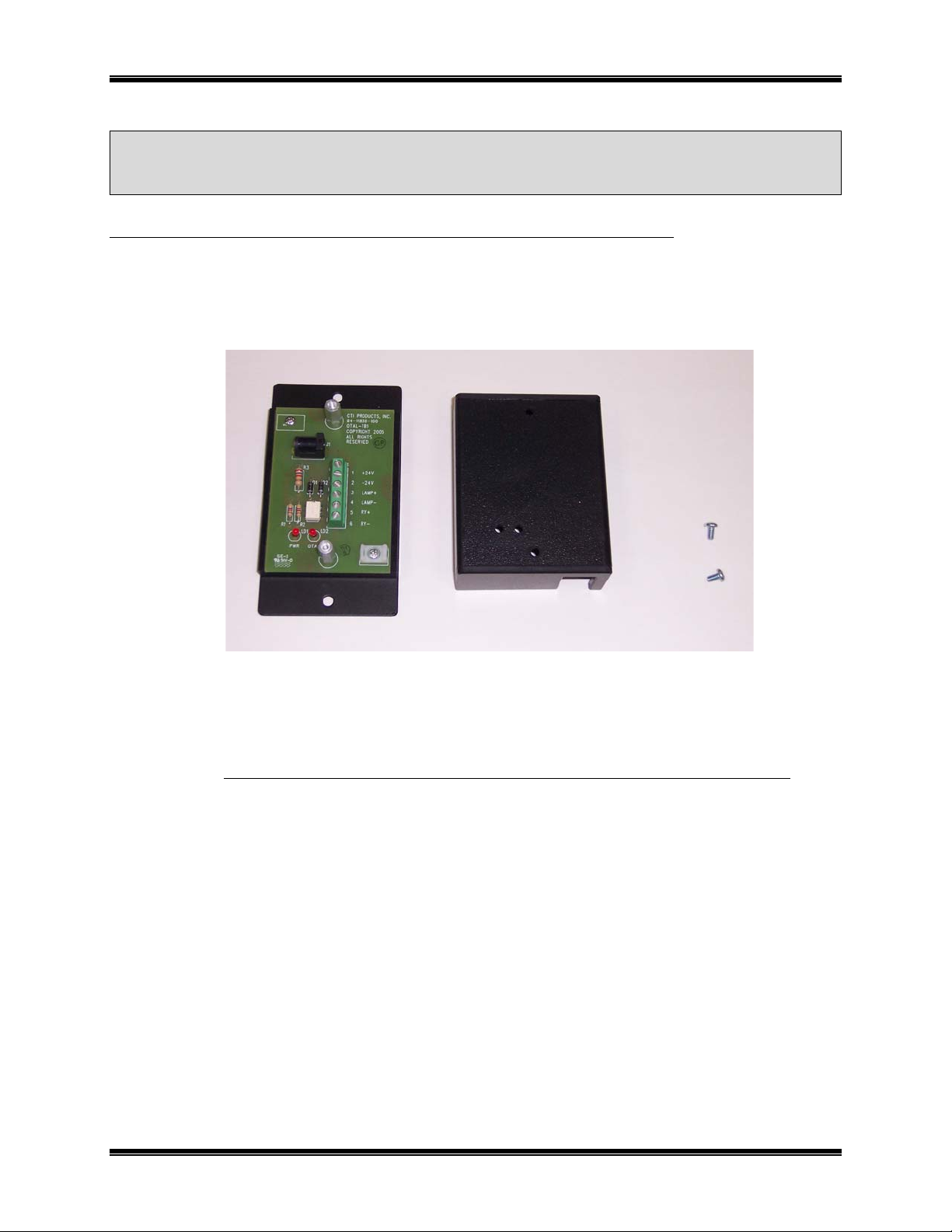
Figure 2 OTAL TB Mounting Plate & Cover Kit
The Mounting Plate & Cover Kit includes the following items:
(1) Mounting Plate
(2) Hex Threaded Standoffs
(1) Plastic Cover
(2) 6-32 x ¼" Philips Head screws
If you ordered multiple kits, they will be bulk-packed.
To install the OTAL Terminal Board, Mounting Plate & Cover Kit:
1. Install OTAL Terminal Board over the threaded studs on the Mounting Plate
2. Install spacers on the exposed studs
3. Connect the wires to the terminal board & strain relieve with a tie-wrap.
4. Install the cover over the board using the screws provided. Be sure not to pinch any wires.
5. Mount the assembly to the mounting surface. Mounting holes will pass a #6 screw.
Terminal Board 6
Page 7

CTI Products, Inc. OTAL Terminal Board User Guide
Figure 3 Board & Spacers Installed Figure 4 Wires Connected
Figure 5 Cover Installed
Terminal Board 7
Page 8

CTI Products, Inc. OTAL Terminal Board User Guide
WIRING
J1 Power Connector
Power can be applied through the DC Power Connector J1:
Pin Function
Center + Supply In (typically 24VDC)
(Paralleled with TB1-1)
Barrel - Supply In (Typically Ground)
(Paralleled with TB1-1)
Table 1 – J1 Power Connector
TB1
Terminal Board TB1 is for the field wiring.
Pin Function
1 + Supply In (Typically +24 VCDC)
(Paralleled with J1-Center)
2 - Supply In (Typically Ground)
(Paralleled with J1-Center)
3 OTAL Lamp +
4 OTAL Lamp 5 + Input from OTAL Relay Closure
(from OTAL Driver Assembly)
6 - Input from OTAL Relay Closure
(from OTAL Driver Assembly)
Table 2 – TB1 Connections
Power may be furnished through either J1 or TB1.
LEDS
Two LEDs are present on the board to help in troubleshooting. The function is marked on the board. When the
cover is installed the LEDs may be seen when looking straight on.
LED Function
Power LED
(Left)
OTAL ON when the OTAL Relay Closure is present.
On when power is present
(Power must also be present)
Terminal Board 8
Page 9

CTI Products, Inc. OTAL Terminal Board User Guide
SPECIFICATIONS
Inputs & Outputs
Power In: 12 to 24 VDC (nominal)
1A maximum
DC Connector: 5.5 mm barrel x 2.5 mm center pin, center positive
Lamp Drive Out 12 to 24 VDC (nominal – depending on power input) at 1A maximum
Control In: Dry Closure or Open Collector/Drain
Voltage level dependent upon power supply to board (12-24 VDC Nominal)
10 mA maximum
Physical
Size: 4.8" x 2.8" x 1.4" (L x W x D)
Terminal Board 9
Page 10

CTI Products, Inc. OTAL Terminal Board User Guide
SCHEMATIC AND LAYOUT
Figure 6 OTAL Terminal Board Schematic
Terminal Board 10
Page 11

CTI Products, Inc. OTAL Terminal Board User Guide
Figure 7 OTAL Terminal Board Layout
Terminal Board 11
Page 12

CTI Products, Inc. OTAL Terminal Board User Guide
LAMP ASSEMBLY
The following lamp assembly and accessories are available:
Part Number Description
99-11844 Lamp Assembly, Red Polycarbonate Resin Lens, LED, IP20
Includes 300mm Pole and Right Angle Bracket
99-11845 Flange Mount
99-11846 Mo unting Pole, 1 meter
Figure 8 Lamp Assembly
Figure 9 Flange Mount with Pole End
Figure 10 300mm Pole and Right Angle
Bracket
Lamp Assembly 12
Page 13

Page 14

 Loading...