

Page 1

OTAL
On The Air Light
Driver Assembly
Hardware Reference Manual
User Guide # S2-61120-100
68-11792-100
Page 2

CTI Products, Inc. OTAL Driver Assembly User Guide
LIMITED WARRANTY. Equipment manufactured by CTI Products, Inc. is warranted to be free from defects in material and workmanship for
a period of ONE (1) YEAR from date of shipment to original purchaser. Under this warranty, our obligation is limited to repairing or replacing
any equipment proved to be defective by our inspection within one year of sale to the original purchaser. This warranty shall not apply to
equipment which has been repaired outside our plant in any way, so as to, in the judgment of CTI Products, Inc. affect its stability or reliability,
nor which has been operated in a manner exceeding its specifications, nor which has been altered, defaced, or damaged by lightning.
CUSTOMER REMEDIES. In the event of a defect, malfunction, or failure to conform to specifications established by the seller during the
period shown, the customer shall call CTI Products, Inc. to obtain a Return Authorization Number and return the product or module, shipping and
insurance prepaid. CTI Products, Inc., will then at its option, either repair or replace the product or module and return it, shipping prepaid, or
refund the purchase price thereof. On-site labor at the purchaser's location is not included in this warranty.
EQUIPMENT NOT MANUFACTURED BY CTI Products, Inc. Equipment not manufactured by CTI Products, Inc. is excluded from this
warranty, but is subject to the warranty provided by its manufacturer, a copy of which will be supplied to you upon specific written request.
NO OTHER WARRANTIES. The foregoing constitutes the sole and exclusive remedy of the buyer and exclusive liability of CTI Products,
Inc., and is in lieu of any and all other warranties expressed or implied or statutory as to merchantability, fitness for purpose sold, description,
quality, productiveness or any other matter.
NO LIABILITY FOR CONSEQUENTIAL DAMAGES. WITHOUT LIMITING THE FOREGOING, IN NO EVENT SHALL CTI
PRODUCTS, INC. OR ITS SUPPLIERS BE LIABLE FOR ANY DAMAG ES WHATSOEVER (INCLUDING, WITHOUT LIMITATION,
SPECIAL, INCIDENTAL OR CONSEQUENTIAL DAMAGES OR FOR LOSS OF BUSINESS PROFITS, BUSINESS INTERRUPTION,
LOSS OF BUSINESS INFORMATION, OR OTHER PECUNIARY LOSS) ARISING OUT OF THE USE OF OR INABILITY TO USE CT I
PRODUCTS, INC. EQUIPMENT BY PURCHASER OR OT HER THIRD PARTY, WHETHER UNDER THEOR Y OF CONTRACT, TORT
(INCLUDING NEGLIGENCE), INDEMNITY, PRODUCT LIABILITY OR OTHERWISE, EVEN IF CTI PRODUCTS, INC. HAS BEEN
ADVISED OF THE POSSIBILITY OF SUCH DAMAGES OR LOSSES. IN NO EV ENT SHALL CTI PRODUCTS, INC.’S, LIABILITY
EXCEED THE TOTAL AMOUNT PAID BY PURCHASER FOR THE EQUIPMENT GIVING RISE TO SUCH LIABILITY.
CTI Products, Inc.
1211 W. Sharon Rd.
Cincinnati, OH 45240
If you have questions about this equipment, call us at:
(513) 595-5900. (8:30 to 5:00 Eastern)
Information contained in this document is subject to change without notice and does not represent a comm itme nt on the part of CTI Products, Inc.
Standard Limited Hardware Warranty
No part of this manual may be reproduced or transmitted in any form or by any means, electronic or mechanical, including photocopying and
recording, for any purpose without the written permission of CTI Products, Inc.
Copyright 2007, CTI Products, Inc. All rights reserved.
MCN is a trademark of CTI Products, Inc. Other trademarks referenced are properties of their respective owners
.
68-11792-100
Page 3

CTI Products, Inc. OTAL Driver Assembly User Guide
TABLE OF CONTENTS
Introduction................................................................................................................................................5
REFERENCE DOCUMENTS ...........................................................................................................................................7
OTAL Driver Logic.....................................................................................................................................8
COR AND PTT OTAL DRIVER LOGIC........................................................................................................................8
COR ONLY OTAL DRIVER LOGIC .............................................................................................................................8
Field Connections......................................................................................................................................9
LOCAL PTT CONNECTIONS ........................................................................................................................................9
REMOTE PTT CIB CONNECTIONS ............................................................................................................................10
REMOTE COR CIB CONNECTIONS ...........................................................................................................................10
OTAL OUTPUTS.......................................................................................................................................................11
LOCAL ALARM / STATUS OUTPUTS ..........................................................................................................................12
Internal Connections...............................................................................................................................13
PTT IIB TO OTAL DRIVER PCB..............................................................................................................................13
COR IIB TO OTAL DRIVER PCB .............................................................................................................................14
OTAL DRIVER PCB TO OTAL CIB.........................................................................................................................15
Jumpering.................................................................................................................................................16
OTAL DRIVER PCB.................................................................................................................................................16
IIB & CIB MODULES................................................................................................................................................17
Module Addressing..................................................................................................................................18
IIB DUAL ADDRESSING............................................................................................................................................18
PC Display................................................................................................................................................19
MCN CONFIG RESOURCES .......................................................................................................................................19
SAMPLE SCREEN.......................................................................................................................................................20
Specifications...........................................................................................................................................21
68-11792-100
Page 4

CTI Products, Inc. OTAL Driver Assembly User Guide
Manual Revisions:
S2-61120-100 Original Release
.
68-11792-100
Page 5
CTI Products, Inc. OTAL Driver Assembly User Guide
INTRODUCTION
The On The Air Light (OTAL) system allows Carrier Operated Relay (COR) signals from remote receivers to
drive On The Air Lamps at consoles. It provides a jumper-selectable option to add Push To Talk (PTT)
qualifier(s) to the COR signals so that the console light displays only when the console is keyed and a carrier is
received at the receiver.
The OTAL system uses standard modules from the MCN (Monitoring and Control Network) to transport the
remote signals. It also uses an OTAL Driver Assembly. This manual covers the OTAL Driver Assembly and
overall OTAL system overview.
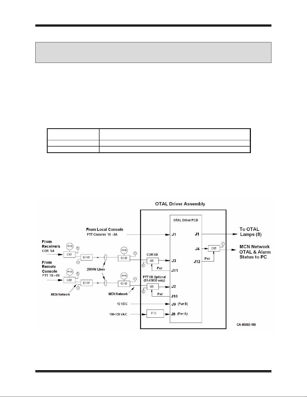
The OTAL Driver Assembly is available in two different versions according to the following table:
Part Number Description
S1-61030
S1-61121
Figure 1 shows a typical OTAL system. It includes the optional Remote PTT circuitry. The Remote PTT and
Remote COR signals connect to remote CIB modules. The data from the remote CIB modules is sent via EXB
Network Extenders to the IIB modules in the OTAL Driver Assembly.
OTAL Driver Assembly with Remote PTT Inputs
OTAL Driver Assembly without Remote PTT Inputs
Figure 1 - Typical OTAL System
Remote requirements to transport the COR and PTT signals vary by system. EXB modules are shown that
utilize 2W/4W leased lines. Other EXB modules are available that use copper or fiber Ethernet, or RS232
channels.
Introduction 5
Page 6

CTI Products, Inc. OTAL Driver Assembly User Guide
Note that the external CIB and EXB modules are not part of the OTAL Driver Assembly, and must be
purchased separately.
The OTAL Driver Assembly has the following features:
• Accepts (8) remote COR inputs via MCN network
• Accepts (8) local PTT inputs
• Accepts (8) remote PTT inputs via MCN network
(optional – S1-61030 only)
• Powered by 100-140 VAC input
• Optional 12 VDC input
• Generates (8) On The Air Light (OTAL) Outputs
• Jumper selectable OTAL Logic:
- COR only OTAL
- COR + PTT OTAL
• Keyup Failure Alarm (when PTT is used)
• Link Status (for both IIB modules)
• Power supply status (for both power inputs)
• OTAL and alarm status outputs (via MCN Network) for display on PCs
• Front panel LED display of
-Local & Remote PTT
-COR signals
-OTAL Signals
-Alarm Signals
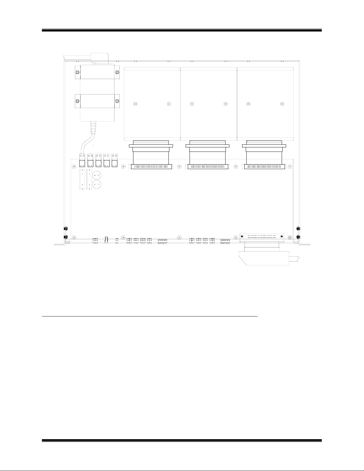
Figure 2 and Figure 3 show the OTAL Driver Assembly front and rear views. Figure 4 shows the top view.
PWR1 OK
PWR2 OK RST
LED LEGEND
COR
PTT A
OTAL
RESET
+5V
LINK 1
PTT A
LINK 2
PTT B
COR
OTAL
PTT B
1234
CB-61030-100 Front View
PTT A
PTT B
OTAL DRIVER
87654321
COR
OTAL
FAILFAIL
5678
Local PTT (PTT A) Inputs
LOCAL I/O
J1
OTAL Outputs
Figure 2 – OTAL Driver Front View
PRODUCTS, INC.
IN OUTNETWORK
OTAL CIB
DC IN
PWR ACT
MODULEGROUP
PRODUCTS, INC.
ERR
IN OUTNETWORK
COR IIB
DC IN
ERR
PWR ACT
MODULEGROUP
CD-61030-100 Rear View
PRODUCTS, INC.
IN OUTNETWORK
PTT IIB
DC IN
ERR
PWR ACT
MODULEGROUP
Figure 3 – OTAL Driver Rear View
Introduction 6
Page 7
CTI Products, Inc. OTAL Driver Assembly User Guide
Power Supply
DC In
MH1
J8 J9 J10 J11 J12
F13 F12
C1
C2
Remote PTT IIB
Ribbon Cable
MH2 MH3 MH4 MH5
RPI-9
15-11766-100
J2
OTAL Driver PCB
MH6 MH7 MH8
LD20
LD21
SW2
LD9 LD13 LD15LD4 LD8LD6LD3 LD5LD2 LD7LD1 LD10 LD11 LD12 LD14 LD16
LD19
LD17
Remote COR IIB
OTAL CIB
Status & Alarms
Ribbon Cable Ribbon Cable
J3
MH9
LD18
Local I/O
J4
MH10
1
J
CC-61030-100 Top View
Figure 4 – OTAL Driver Top View
REFERENCE DOCUMENTS
S2-61145 OTAL Terminal Board and Lamp Assembly Manual
S2-60426 CIB Comparator Interface Manual
S2-60400 IIB I/O Module Manual
S2-60425 Monitoring and Control Network System Manual
S2-60596 EXB–IM & EXB-232 Network Extender Manual
S2-61089 EXB-IP Network Extender Manual
Local PTTs in & OTALs Out
Introduction 7
Page 8

CTI Products, Inc. OTAL Driver Assembly User Guide
OTAL DRIVER LOGIC
The OTAL Driver Assembly features two types of OTAL logic, depending on jumper settings selected:
• COR + PTT OTAL Logic
(Enabled with E4 & E10 jumpers OUT)
• COR Only OTAL Logic
(Enabled with E4 & E10 jumpers IN)
COR AND PTT OTAL DRIVER LOGIC
Output Logic
OTAL Out = (Local PTT OR Remote PTT) AND COR
Keyup Fail Output Logic
The Keyup Fail signal is derived from the PTT signals and the COR signals. If a PTT is active and there is no
COR within a fixed time (typically 1 second), the Keyup Fail will become active. The time delay allows for
tone keying, keyup delay, and COR delay. The Keyup Fail feeds the Status CIB and can be indicated on the
MCN PC.
Keyup Fail Alarm = (Local PTT OR Remote PTT) AND NOT COR
COR ONLY OTAL DRIVER LOGIC
The COR Only logic is as follows:
OTAL Output = COR
Keyup Alarm = not applicable (PTT signals are not used in the OTAL logi c)
OTAL Logic 8
Page 9

CTI Products, Inc. OTAL Driver Assembly User Guide
FIELD CONNECTIONS
LOCAL PTT CONNECTIONS
Local PTT signals are connected to J1 of the OTAL Driver PCB. (PTT inputs are not required if COR Only
OTAL Logic is used.)
Local PTT signals shall be either:
Isolated Form A Relay Contacts (or opto-isolated relay outputs)
closed when PTT signal is present.
Logic Outputs - Negative Ground, Active Low when PTT is active.
They must be capable of:
Up to +20 VDC Open Circuit
Sinking a minimum of 30 mA when active
Maximum of 0.2 V when active
Signals must not drive other equipment.
The Local PTT signals appear on the first 8 pairs of J1 as follows:
OTAL J1 Wire Color Signal
1 Blu/Wht PTT 1A
26 Wht/Blu Gnd 1A
2 Org/Wht PTT 2A
27 Wht/Org Gnd 2A
3 Grn/Wht PTT 3A
28 Wht/Grn Gnd 3A
4 Brn/Wht PTT 4A
29 Wht/Brn Gnd 4A
5 Slt/Wht PTT 5A
30 Wht/Slt Gnd 5A
6 Blu/Red PTT 6A
31 Red/Blu Gnd 6A
7 Org/Red PTT 7A
32 Red/Org Gnd 7A
8 Grn/Red PTT 8A
33 Red/Grn Gnd 8A
(The “A” suffix on the PTT signals indicates the Local PTT.)
The ground signals are tied together on the OTAL Driver board. It is preferred that the PTT signals be wired to
J1 as pairs, with separate grounds.
Field Connections 9
Page 10

CTI Products, Inc. OTAL Driver Assembly User Guide
REMOTE PTT CIB CONNECTIONS
Remote PTT signals are connected to J1 on a remote CIB. (See Figure 1.) PTT inputs are not required if COR
Only OTAL Logic is used.
Remote PTT signals shall be either:
Isolated Form A Relay Contacts (or opto-isolated relay outputs)
closed when PTT signal is present.
Logic Outputs - Negative Ground, Active Low when PTT is active.
They must be capable of:
Up to +20 VDC Open Circuit
Sinking a minimum of 30 mA when active
Maximum of 0.2 V when active
Signals must not drive other equipment.
The Remote PTT signals appear on the following pins of J1 of the remote PTT CIB module as follows:
Remote PTT CIB J1 Wire Color CIB Function OTAL System Function
1 Blu/Wht Ground Ground-Common
22 Org/Vio Rx 1 PTT 1B input
47 Vio/Org Rx 2 PTT 2B input
16 Blu/Yel Rx 3 PTT 3B input
41 Yel/Blu Rx 4 PTT 4B input
10 Slt/Red Rx 5 PTT 5B input
35 Red/Slt Rx 6 PTT 6B input
4 Brn/Wht Rx 7 PTT 7B input
29 Wht/Brn Rx 8 PTT 8B input
The “B” suffix on the PTT signals indicates the Remote PTT.
REMOTE COR CIB CONNECTIONS
The Remote COR signals are connected to J1 on a remote CIB. (See Figure 1.)
Remote COR signals shall be either:
Isolated Form A Relay Contacts (or opto-isolated relay outputs)
closed when a carrier is detected.
Logic Outputs - Negative Ground, Active Low when a carrier is active.
They must be capable of:
Up to +20 VDC Open Circuit
Sinking a minimum of 30 mA when active
Maximum of 0.2 V when active
Signals must not drive other equipment.
Field Connections 10
Page 11

CTI Products, Inc. OTAL Driver Assembly User Guide
The Remote COR signals appear on the following pins of J1 of the remote COR CIB module as follows:
Remote COR CIB J1 Wire Color CIB Function OTAL System Function
1 Blu/Wht Ground Ground-Common
22 Org/Vio Rx 1 COR 1 input
47 Vio/Org Rx 2 COR 2 input
16 Blu/Yel Rx 3 COR 3 input
41 Yel/Blu Rx 4 COR 4 input
10 Slt/Red Rx 5 COR 5 input
35 Red/Slt Rx 6 COR 6 input
4 Brn/Wht Rx 7 COR 7 input
29 Wht/Brn Rx 8 COR 8 input
OTAL OUTPUTS
The OTAL outputs are opto-isolated solid state relays. They are active in the closed position. These outputs
appear on the last 8 pairs of J1 of the OTAL Driver Assembly as follows:
OTAL Driver Assembly J1 Wire Color Signal
43
18
44
19
45
20
46
21
47
22
48
23
49
24
50
25
The solid-state relay outputs listed above are polarity-sensitive, and are curren t-limited to 0.5A. Typical lamp
connections are shown below.
Yel/Grn OTAL Ry 1+
Grn/Yel OTAL Ry 1Yel/Brn OTAL Ry 2+
Brn/Yel OTAL Ry 2-
Yel/Slt OTAL Ry 3+
Slt/Yel OTAL Ry 3Vio/Blu OTAL Ry 4+
Blu/Vio OTAL Ry 4-
Vio/Org OTAL Ry 5+
Org/Vio OTAL Ry 5Vio/Grn OTAL Ry 6+
Grn/Vio OTAL Ry 6Vio/Brn OTAL Ry 7+
Brn/Vio OTAL Ry 7-
Vio/Slt OTAL Ry 8+
Slt/Vio OTAL Ry 8-
Figure 5 – Typical Lamp Connections
Field Connections 11
Page 12

CTI Products, Inc. OTAL Driver Assembly User Guide
LOCAL ALARM / STATUS OUTPUTS
The Local Alarm / Status outputs are active-low logic levels, ground-referenced. They appear on the following
pairs of connector J1 of the OTAL Driver Assembly:
OTAL Driver Assembly J1 Wire Color Signal
34
9
35
10
36
11
37
12
Red/Brn Gnd
Brn/Red Link OK Out 1 (Remote IIB Link)
Red/Slt Gnd
Slt/Red Link OK Out 2 (COR IIB Link)
Blk/Blu Gnd
Blu/Blk Pwr OK Out 1
Blk/Org Gnd
Org/Blk Pwr OK Out 2
Field Connections 12
Page 13

CTI Products, Inc. OTAL Driver Assembly User Guide
INTERNAL CONNECTIONS
PTT IIB TO OTAL DRIVER PCB
The PTT IIB is connected to J2 on the OTAL Driver board through a ribbon cable as follows:
PTT IIB J1 IIB I/O IIB Function
1
4
29
30
19
44
12
37
6
31
18
26
Gnd Ground 1 Ground
I Link Fail Enable 7 Ground
I Link Fail Invert 8 Ground
O Fail 8 / Link Fail 10 LinkUp1
O Rx 1 37 PTT 1B
O Rx 2 38 PTT 2B
O Rx 3 23 PTT 3B
O Rx 4 24 PTT 4B
O Rx 5 11 PTT 5B
O Rx 6 12 PTT 6B
O Rx 7 35 PTT 7B
O Rx 8 2 PTT 8B
OTAL Driver PCB
Connector J2
OTAL System
Function
All signals are active low.
The Link Fail Enable and Link Fail Invert signals are inputs to the IIB. They are read-only at power-up of the
IIB. Therefore, the IIB must be connected to the OTAL Driver PCB before it is powered up. Otherwise, the
Link UP signal will not be active.
Internal Connections 13
Page 14

CTI Products, Inc. OTAL Driver Assembly User Guide
COR IIB TO OTAL DRIVER PCB
The COR IIB is connected to J3 on the OTAL Driver board through a ribbon cable as follows:
COR IIB J1 IIB I/O IIB Function
1
4
29
30
19
44
12
37
6
31
18
26
Gnd Ground 1 Ground
I Link Fail Enable 7 Ground
I Link Fail Invert 8 Ground
O Fail 8 / Link Fail 10 LinkUp2
O Rx 1 37 COR 1
O Rx 2 38 COR 2
O Rx 3 23 COR 3
O Rx 4 24 COR 4
O Rx 5 11 COR 5
O Rx 6 12 COR 6
O Rx 7 35 COR 7
O Rx 8 2 COR 8
OTAL Driver PCB
Connector J3
OTAL System
Function
All signals are active low.
The Link Fail Enable and Link Fail Invert signals are inputs to the IIB. They are read only at power-up of the
IIB. Therefore, the IIB must be connected to the Otal Driver PCB before it is powered up. Otherwise, the Link
UP signal will not be active.
Internal Connections 14
Page 15

CTI Products, Inc. OTAL Driver Assembly User Guide
OTAL DRIVER PCB TO OTAL CIB
The OTAL CIB is connected to J4 of the OTAL Driver board through a ribbon cable. The OTAL CIB sends the
OTAL signals, the Local PTT signals, and the Power Supply and Link Up signals to the MCN network.
OTAL Driver PCB
Connector J4
1 Ground
41 OTAL Out 1
42 OTAL Out 2
29 OTAL Out 3
30 OTAL Out 4
17 OTAL Out 5
18 OTAL Out 6
5 OTAL Out 7
6 OTAL Out 8
43 PTT Out 1A
44 PTT Out 2A
31 PTT Out 3A
32 PTT Out 4A
19 PTT Out 5A
20 PTT Out 6A
7 PTT Out 7A
8 PTT Out 8A
45 Fail Out 1
46 Fail Out 2
33 Fail Out 3
34 Fail Out 4
21 Fail Out 5
22 Fail Out 6
9 Fail Out 7
10 Fail Out 8
39 Link OK Out 1
40 Link OK Out 2
27 Pwr OK Out 1
28 Pwr OK Out 2
OTAL System
Function
OTAL CIB J1 CIB I/O CIB Function
1
21
46
15
40
9
34
3
28
22
47
16
41
10
35
4
29
23
48
17
42
11
36
5
30
20
45
14
39
Gnd Ground
I Vote 1
I Vote 2
I Vote 3
I Vote 4
I Vote 5
I Vote 6
I Vote 7
I Vote 8
I Rx 1
I Rx 2
I Rx 3
I Rx 4
I Rx 5
I Rx 6
I Rx 7
I Rx 8
I Fail 1
I Fail 2
I Fail 3
I Fail 4
I Fail 5
I Fail 6
I Fail 7
I Fail 8
I/O Dis 1
I/O Dis 2
I/O Dis 3
I/O Dis 4
All signals are active low.
Internal Connections 15
Page 16

CTI Products, Inc. OTAL Driver Assembly User Guide
JUMPERING
OTAL DRIVER PCB
Jumper Function Position Operation Default
E1 EPLD Test 1 n/a Out
E2 EPLD Test 2 n/a Out
E3 EPLD Test 3 n/a Out
E4 Chan 1-4
OTAL Logic
E5 Chan 1-4 Hardware A
E6 Chan 5-8 Hardware A
E7 Snubber 2
Chan 5-8
U15 & U17
E8 Snubber 1
Chan 1-4
U12 & U13
E9 Chassis Gnd to
Circuit Gnd
E10 Chan 5-8
OTAL Logic
J6 Chan 1-4
CPU Signals
J7 Chan 5-8
CPU Signals
Out
In
B
B
Out
In
Out
In
In
Out
In
Out
In
Out
In
COR + PTT
COR Only
CPU
PLD
CPU
PLD
No Snubber
+12V Snubber
No Snubber
+12V Snubber
COR + PTT
COR Only
Programming
Operating
Programming
Operating
In
A
A
In
In
In
In
In
Jumpering 16
Page 17

CTI Products, Inc. OTAL Driver Assembly User Guide
IIB & CIB MODULES
Jumper Function Position Function Default
E1A Output Enable In
Out
E1B Input Pull-up Voltage In
Out
E1 A
E1 B
CA-80024-100
Mon 7 Enabled
Mon 7 Disabled
5 Vdc
15 Vdc
In
Out
Jumpering 17
Page 18

CTI Products, Inc. OTAL Driver Assembly User Guide
MODULE ADDRESSING
The MCN Modules in the OTAL system must be addressed properly: Some requirements for addressing are:
All MCN modules must be uniquely addressed; no two modules may be set to the same
Group & Module address.
There may be restrictions on what MCN Group numbers may be used in a particular part of a
large network. If you have a Custom Engineered System, follow the addressing set for each
module as specified in your system documentation.
IIB modules must have two addresses set: first, the address of the CIB module it talks to and
second, its own address. The PTT IIB (if used) will talk to the PTT CIB. The COR IIB will
talk to the COR CIB.
IIB DUAL ADDRESSING
Use the following steps to set up the addressing of the IIB:
1. Set Option Switch 4 Up.
2. Set the Group & Module hex rotary switches to the address of the CIB that the IIB will talk to.
3. Press the Reset button. The Reset LED will blink and then come on solid.
4. Set Option Switch 4 Down.
5. Set the Group & Module hex rotary switches to the IIB’s own address
6. Press the Reset button. The reset LED will go out.
Module Addressing 18
Page 19

CTI Products, Inc. OTAL Driver Assembly User Guide
PC DISPLAY
The MCN PC can display the status of a number of points in the OTAL system:
Signal From the following module
Local PTT (1-8) OTAL CIB in the OTAL Driver Assembly
Remote PTT (1-8) Remote PTT CIB (if used)
COR Signals (1-8) Remote COR CIB
OTAL Signal (1-8) OTAL CIB in the OTAL Driver Assembly
Keyup Fail (1-8) OTAL CIB in the OTAL Driver Assembly
OTAL Power Status (1-2) OTAL CIB in the OTAL Driver Assembly
IIB Link Status (1-2) OTAL CIB in the OTAL Driver Assembly
MCN CONFIG RESOURCES
Use the following resources in the MCN Config program to configure an OTAL system in the MCN system:
Module Device in MCN Config
PTT CIB CIB (8 PTT signals)
COR CIB CIB (8 COR signals)
OTAL CIB CIB OTAL Alarm
(8 OTAL sections – OTAL & Keyup Fail))
The OTAL CIB Alarm device has the following 12 Functi on Bloc ks (Receivers ):
• (8) OTAL & Keyup Fail
• IIB Link 1 (from Remote PTT CIB)
• IIB Link 2 (from Remote COR CIB)
• OTAL PS A (typically AC Power)
• OTAL PS B (typically DC Power)
Function Block Display Table
Remote PTT PTT
COR COR
OTAL & Keyup Fail CIB OTAL Alarm
(Displays Local PTT, OTAL & Keyup Fail)
OTAL PS OK-Fail
IIB Link OK-Fail
PC Display 19
Page 20

CTI Products, Inc. OTAL Driver Assembly User Guide
SAMPLE SCREEN
A sample screen (including Remote PTT inputs and COR+PTT OTAL Logic) is shown below:
OTAL Screen 1
Local PTTs Remote PTTs
OTAL 1 AC OK CIB Link OK CIB Link OK OTAL DC OK
Chan 1 Chan 1 Chan 1 Chan 1
Chan 2 PTT Chan 2 Chan 2 COR Chan 2 OTAL
Chan 3 Chan 3 Chan 3 Chan 3
Chan 4 Chan 4 PTT Chan 4 COR Chan 4 OTAL
Chan 5 Chan 5 Chan 5 Chan 5
Chan 6 Chan 6 Chan 6 COR Chan 6
Chan 7 Chan 7 Chan 7 COR Chan 7
Chan 8 Chan 8 Chan 8 COR Chan 8
OTAL 2 AC OK CIB Link OK CIB Link OK OTAL DC ON
Chan 9 Chan 9 Chan 9 Chan 9
Chan 10 PTT Chan 10 Chan 10 Chan 10 Fail
Chan 11 Chan 11 Chan 11 Chan 11
Chan 12 Chan 12 PTT Chan 12 Chan 12 Fail
Chan 13 Chan 13 Chan 13 Chan 13
Chan 14 Chan 14 Chan 14 Chan 14
Chan 15 Chan 15 Chan 15 Chan 15
Chan 16 Chan 16 Chan 16 Chan 16
• The channel names can be customized in the MCN Config program.
• The status of the power, along with the status of the CIB Links are shown above each group of 8 channels.
• Channel 2 shows a channel that is normally keyed using the Main PTT. The COR signal is active and the
OTAL Driver Assembly is generating an OTAL signal.
• Channel 4 shows a channel with normal keying using the Remote PTT.
• Channels 6-8 show receive traffic. Since there are no PTT signals (and the system is using COR + PTT OTAL
Logic), the OTAL lights are off.
• Channel 10 shows an abnormal situation. The Main PTT signal is active, but there is no received signal and
therefore, no OTAL light. This could be caused by any number of problems, inclu ding a bad transmitter, bad
phone line, or a bad receiver.
• Channel 12 shows a similar abnormal situation, but with an attempted transmission using the Remote PTT.
CORs OTAL Logic
PC Display 20
Page 21

CTI Products, Inc. OTAL Driver Assembly User Guide
SPECIFICATIONS
Size 19” Rack Mount, 1 RU High
17.5” W x 14.0” D x 1.75” H
Weight 10 lbs
Temperature 0 - 50 ºC
Humidity 10 - 95% non-condensing
Input Power
Main
Standby
Fuse
COR Remote Inputs
Quantity
Front Panel Indication
Signal Levels
PTT Remote Inputs
Quantity
Front Panel Indication
Signal Levels
PTT Local Inputs
Quantity
Front Panel Indication
Signal Level – Low
OTAL (On the Air Light) Outputs
Quantity
Type
Current
Voltage
Status and Alarm Local Signals
Power OK Out 1, Power OK Out 2
Quantity
Front Panel Indication
Type
Current
Voltage
Link OK Out 1, Link OK Out 2
Quantity
Front Panel Indication
Type
Current
Voltage
Status and Alarm Remote Signals to PC
Local PTT Out 1 - 8
Fail Out 1 - 8
OTAL Out 1 - 8
Power OK Out 1 & 2
Link OK Out 1 & 2
100-240 Vac / 47-63 Hz / 12 Watts max.
12 Vdc / 12 Watts max.
2A, 250V, Fast Blow
(Via remote CIB module - purchased separately)
8
LEDs
See CIB Manual S2-60442
(Via remote CIB module - purchased separately)
8
LEDs
See CIB Manual S2-60442
8
LEDs
Active Low, 30ma Sink, 0.2Vdc max.
8
Opto-Isolated Solid State Relays
0.5 A max
30 Vdc max
2
LEDs
Opto-Isolated Solid State Relays, Polarity Sensitive
0.5 A max
30 Vdc max
2
LEDs
Active Low, referenced to ground
150 mA max (sink)
30 Vdc max
Via OTAL internal CIB and MCN Network
Specifications 21
Page 22

 Loading...