

Page 1

NCB/EL™ Etherlon
and
NCB/FL™ Fiberlon
Network Combiner Module
for Ethernet and Fiber Channels
TM
TM
Wide Area Routers for LONW
User Guide # S2-60759-200
ORKS
®
Networks
68-11324-200
Page 2

CTI Products, Inc. NCB-EL/FL User Guide
Radio Frequency Emissions and Immunity
This equipment generates, uses, and can radiate radio frequency energy and, if not installed and used in accordance with the instruction manual,
may cause harmful interference to radio communications. Operation of this equipment in a residential area is likely to cause harmful interference
in which case the user will be required to correct the interference at his own expense. Changes or modifications to this unit not expressly
approved by the party responsible for compliance could void the user’s authority to operate the equipment. Limits specified in the standards listed
below are designed to provide reasonable protection against harmful interference when the equipment is operated in a commercial environment.
UNITED STATES:
FCC Rules.
CANADA:
Cet appareil numérique de la classe A respecte toutes les exigences du Règlement sur le matériel brouilleur du Canada.
EUROPE:
IEC801-4, and EN55022. This equipment complies with the requirements of the following directives: Low Voltage Directive 73/23/EEC, EMC
Directive 89/336/EEC, and 93/68/EEC Harmonization of CE Marking
This Class A digital apparatus meets all requirements of the Canadian Interference-Causing Equipment Regulations.
This equipment has been tested and found to comform with the following standards: EN60950, EN50082-1, IEC801-2, IEC801-3,
This equipment has been tested and found to comply with the limits for a Class A digital device, pursuant to Part 15 of the
Standard Limited Hardware Warranty
LIMITED WARRANTY.
a period of ONE (1) YEAR from date of shipment to original purchaser. Under this warranty, our obligation is limited to repairing or replacing
any equipment proved to be defective by our inspection within one year of sale to the original purchaser. This warranty shall not apply to
equipment which has been repaired outside our plant in any way, so as to, in the judgment of CTI Products, Inc. affect its stability or reliability,
nor which has been operated in a manner exceeding its specifications, nor which has been altered, defaced, or damaged by lightning.
CUSTOMER REMEDIES.
period shown, the customer shall call CTI Products, Inc. to obtain a Return Authorization Number and return the product or module, shipping and
insurance prepaid. CTI Products, Inc., will then at its option, either repair or replace the product or module and return it, shipping prepaid, or
refund the purchase price thereof. On-site labor at the purchaser's location is not included in this warranty.
EQUIPMENT NOT MANUFACTURED BY CTI Products, Inc.
warranty, but is subject to the warranty provided by its manufacturer, a copy of which will be supplied to you upon specific written request.
NO OTHER WARRANTIES.
Inc., AND IS IN LIEU OF ANY AND ALL OTHER WARRANTIES EXPRESSED OR IMPLIED OR STATUTORY AS TO
MERCHANTABILITY, FITNESS FOR PURPOSE SOLD, DESCRIPTION, QUALITY, PRODUCTIVENESS OR ANY OTHER MATTER.
NO LIABILITY FOR CONSEQUENTIAL DAMAGES.
PRODUCTS, INC. OR ITS SUPPLIERS BE LIABLE FOR ANY DAMAGES WHATSOEVER (INCLUDING, WITHOUT LIMITATION,
SPECIAL, INCIDENTAL OR CONSEQUENTIAL DAMAGES OR FOR LOSS OF BUSINESS PROFITS, BUSINESS INTERRUPTION,
LOSS OF BUSINESS INFORMATION, OR OTHER PECUNIARY LOSS) ARISING OUT OF THE USE OF OR INABILITY TO USE CTI
PRODUCTS, INC. EQUIPMENT BY PURCHASER OR OTHER THIRD PARTY, WHETHER UNDER THEORY OF CONTRACT, TORT
(INCLUDING NEGLIGENCE), INDEMNITY, PRODUCT LIABILITY OR OTHERWISE, EVEN IF CTI PRODUCTS, INC. HAS BEEN
ADVISED OF THE POSSIBILITY OF SUCH DAMAGES OR LOSSES. IN NO EVENT SHALL CTI PRODUCTS, INC.’S, LIABILITY
EXCEED THE TOTAL AMOUNT PAID BY PURCHASER FOR THE EQUIPMENT GIVING RISE TO SUCH LIABILITY.
Equipment manufactured by CTI Products, Inc. is warranted to be free from defects in material and workmanship for
In the event of a defect, malfunction, or failure to conform to specifications established by the seller during the
Equipment not manufactured by CTI Products, Inc. is excluded from this
The foregoing constitutes the sole and exclusive remedy of the buyer and exclusive liability of CTI Products,
WITHOUT LIMITING THE FOREGOING, IN NO EVENT SHALL CTI
Location
CTI Products, Inc
:
1211 West Sharon Road
Cincinnati, OH 45240 USA
Phone
: +1.513.595.5900
Fax
: +1.513.595.5983
Web
: www.ctiproducts.com
E-mail, Sales
Technical Support
Information contained in this document is subject to change without notice and does not represent a commitment on the part of CTI
Products, Inc. No part of this manual may be reproduced or transmitted in any form or by any means, electronic or mechanical, including
photocopying and recording, for any purpose without the written permission of CTI Products, Inc.
This manual describes products which include copyrighted CTI Products, Inc. computer programs in semiconductor memory. CTI
Products, Inc. reserves all rights for these programs, including the exclusive right to copy or reproduce the copyrighted computer programs
in any form. No copyrighted computer program contained in products described in this manual may be copied, reproduced, decompiled,
disassembled, or reversed engineered in any manner without express written permission of CTI Products, Inc. The purchase of products
from CTI Products, Inc. shall not be deemed to grant either directly or by implication, estoppel, or otherwise, any license under the
copyrights, patents, or patent applications of CTI Products, Inc., except for the normal non-exclusive, royalty fee license to use that arises
by operation of law in the sale of the product.
Copyright (c) 1995-2001 CTI Products, Inc. All rights reserved
NCB, NCB/EL, NCB/FL, Etherlon, Fiberlon and WON are trademarks of CTI Products, Inc. Echelon, LON,
Neuron are U.S. registered trademarks of Echelon Corporation.
: info@ctiproducts.com
: lwsupport@ctiproducts.com
ONWORKS
L
ONTALK
,
L
, and
68-11324-200
Page 3

CTI Products, Inc. NCB-EL/FL User Guide
ABLE OF CONTENTS
T
QUICK-START GUIDE ............................................................................................................................................ 1
1. INTRODUCTION................................................................................................................................................... 2
HAT IS AN
W
EFERENCE DOCUMENTS
R
RONT PANEL
F
EAR PANEL
R
NCB? .................................................................................................................................................... 2
........................................................................................................................................... 4
............................................................................................................................................................ 5
.............................................................................................................................................................. 6
2. INSTALLATION.................................................................................................................................................... 7
TEP
S
TEP
S
TEP
S
TEP
S
TEP
S
TEP
S
TEP
S
NSTALLING ADDITIONAL
I
NSTALL ETHERPLUG CONFIGURATION SOFTWARE
1 . I
DD
2. A
3. S
4. E
5. D
6. P
7. C
NCB U
TART ETHERPLUG
DIT
OWNLOAD
HYSICALLY INSTALL
OMMISSION THE ROUTERS AND CONTROL NEURON PROCESSORS
NITS TO THE NETWORK DATABASE
.................................................................................................................................... 10
DDRESS PARAMETERS
IP A
DDRESS PARAMETERS TO
IP A
S INTO THE
NCB
NITS AFTER INITIAL INSTALLATION
NCB U
................................................................................................................ 12
NCBS V
ETWORK
IP N
.................................................................................... 8
.......................................................................................... 8
IA SERIAL PORT
................................................................................. 14
......................................................... 13
........................................................... 16
..................................................................... 17
3. NETWORK VARIABLE (NV) CONTROL....................................................................................................... 18
ONFIGURATION OBJECT
C
......................................................................................................................................... 18
4. ETHERPLUG ADDITIONAL FUNCTIONS .................................................................................................... 20
RINTING INFORMATION FROM ETHERPLUG
P
PDATING FIRMWARE IN THE
U
MPORTING/EXPORTING ETHERPLUG CONFIGURATION DATA
I
THER RIGHT-CLICK MEMBER FUNCTIONS
O
NCB U
............................................................................................................ 20
NIT
................................................................................................................ 20
................................................................................. 20
............................................................................................................. 20
APPENDIX................................................................................................................................................................ 21
PPENDIX
A
PPENDIX
A
PPENDIX
A
PPENDIX
A
PPENDIX
A
PPENDIX
A
ACTORY DEFAULT CONFIGURATION
A. F
OUNTING OPTIONS
B. M
ONNECTOR DETAILS
C. C
ROUBLESHOOTING
D. T
PECIFICATIONS
E. S
DDRESSING
F. IP A
.......................................................................................................................... 23
........................................................................................................................ 26
........................................................................................................................... 28
................................................................................................................................. 32
.................................................................................................................................. 33
................................................................................................ 21
INDEX........................................................................................................................................................................ 36
This manual covers NCB/EL and NCB/FL units of Revision 200 or higher and EtherPlug
software revision 1.00 or higher. The NCB Unit Revision can be found on the rear of the unit
following the letter “U”. The EtherPlug software revision can be found on the Help/About
screen of the program. If the revision of the product in hand is greater than that shown
above, there may be additional features supported by the product that are not covered in this
manual.
68-11324-200
Page 4

CTI Products, Inc. NCB-EL/FL User Guide
UICK
Q
This Quick Start Guide provides a concise series of steps to get a pair of the NCB-Etherlon or NCB-Fiberlon
modules “up and running” quickly so that initial operation may be confirmed.
It is highly recommended that a pair of NCB-Etherlon or NCB-Fiberlon modules be tested in your application
by first connecting them “back-to-back” with the 10BaseT or fiber crossover cable included with this shipment.
Once operation is confirmed using this connection scheme, continue by reconfiguring the IP addressing
information and connecting the NCB modules to the actual Ethernet communications channel to be used.
TART GUIDE
-S
NOTE: DO NOT connect the NCB-Etherlon or NCB-Fiberlon modules to a live IP network
until they have been reconfigured with new IP addresses and subnet mask supplied by the
network manager. Network-wide problems could arise from connecting devices to a network
without coordination of addressing information. See the Installation section of this manual
for full information.
Set Option Switches and Make Back-to-Back Connection
For the
For the
NCB-Etherlon:
•
•
OPTION
Set
Connect the NCB units “back-to-back” via the “
using the supplied 10BaseT crossover cable (#S2-60760-100).
NCB-Fiberlon:
switch positions 1 through 8 on the rear of both NCB units to the UP position.
10BaseT
” connector on the rear of each NCB unit
•
•
•
Connect LONW
Once the above steps are completed, proceed by:
•
•
Once properly connected and powered, the “ERR” LED will be off on both units and they are now ready for
use. Using the
ONTALK
L
OPTION
Set
positions 7 and 8 to the DOWN position.
Connect the external fiber transceiver units to the
the transceiver with the slide lock. Verify that the
Connect the NCB units “back-to-back” by attaching the
port of the other fiber transceiver, and vice-versa.
Connect
45s and the screw-terminal connector are in parallel). If using the RJ-45 connector(s), connect to pins
1 & 2 (the right-most two pins).
Connect power to the NCB units via the rear panel “DC IN” connector. The units can be powered-up
in any sequence.
packets entering one NCB unit exit the other and vice-versa.
switch positions 1 through 6 on the rear of both NCB units to the UP position and
AUI
connector on the rear of the NCB unit. Secure
is in the OFF position.
ORKS
ONWORKS
L
ONWORKS
L
Network and Power
network devices to the “
network devices attached to the
NETWORK
SQE Test Switch
XMT
port on one fiber transceiver to the
” connectors of each NCB unit (both RJ-
network
connectors of each NCB unit, verify that
RCV
Quick-Start Guide 1
Page 5
CTI Products, Inc. NCB-EL/FL User Guide
NTRODUCTION
1. I
HAT ARE
W
NCB U
NITS
?
The Network Combiner NCBTM Module is a device that, when used in pairs,
allows multiple
ONWORKS
L
networks to be connected in real-time, spanning
distances from building-wide to worldwide. The communication channel
spanning the distance between local networks can be any copper or fiber Ethernet
Read this
section to learn
the general
function and
capabilities of an
NCB Router
channel that is capable of carrying IP (Internet Protocol) data. Data transfer
between distant networks via NCB modules is "live", delayed only by the transit
time through the routers and Ethernet channel.
The NCB module uses router technology so that no custom coding or additional hardware is necessary to
seamlessly connect multiple networks across very large distances. The NCB module is self-contained, easily
configured with standard network management tools, and requires no custom programming or coding changes
in system nodes.
Both the NCB-Etherlon and the NCB-Fiberlon utilize the IP protocol over an Ethernet media and both can
coexist on a wide-area IP network with other IP devices such as workstations, servers, and IP routers.
Additionally, they can exist on
dedicated
Ethernet IP networks, where the only devices on the network are
NCBs and (optionally) physical layer hubs. The most common occurrence of a dedicated network is a set of
NCB-Fiberlons connected with dedicated fiber.
Basic Application
A basic application of the NCB module is where two multi-node
beyond the reach of conventional wired media, need to be interconnected, as in Figure 1. This distance could be
across a large building, business campus, city, etc. Using the NCB module, this interconnection is
accomplished using one NCB module local to each network site and an Ethernet channel connecting the NCB
modules. Additional networks can be added to this unified network by simply adding an NCB module for each
network.
ONWORKS
L
networks, separated by a distance
BUILDING 1 BUILDING 2
LONWORKS
NODE
LONWORKS
NODE
LONWORKS
NODE
NCB
LONWORKS
NODE
Ethernet
Channel
LONWORKS
NODE
NCB
LONWORKS
NODE
LONWORKS
NODE
LONWORKS
NODE
CA-80070-100
Figure 1 Networks in two buildings connected with NCB modules
Block Diagram
There are three sources of message packets within the NCB module. The first source is the
NETWORK
connector on the front of the unit. The second is the Ethernet media connectors on the rear of the
unit. (Note that although 10BaseT and AUI connectors exist, only one can be used at a time.) The third source
is the Control Neuron Processor. Message packets originating from any of these sources are sent to the other
two. This message packet flow is shown in the block diagram of Figure 2.
2. Installation 2
ONWORKS
L
Page 6
CTI Products, Inc. NCB-EL/FL User Guide
“NETWORK”
Connector
LONWORKS
NETWORK
“DC IN”
Connector
LONWORKS
TRANSCEIVER
SMX
TRANSCEIVER
POWER
SUPPLY
Side
B
ROUTER
Side
A
CONTROL
NEURON
PROCESSOR
“10BaseT”
Connector
“AUI”
Connector
Figure 2 NCB Network Combiner Block Diagram
To
Ethernet
Channel
•
The “NETWORK” connector attaches to the local
internal to the NCB module and is associated with
•
One of the Ethernet connectors attaches to the Ethernet channel, providing communication to additional
NCB modules at remote sites. These ports are associated with
•
The Control Neuron Processor allows network management messages to be sent to the NCB module for
control and status monitoring and is associated with
LONW
The local
Network Transceivers
ORKS
ONWORKS
L
networks at different sites do not need to use the same network transceiver type. For
ONWORKS
L
Side B
of the internal router.
Side A
Side A
of the internal router.
network using a compatible transceiver
of the internal router.
example, an FTT-10A network, a TPT/XF-78 network, and a PLT-22 network can all be interconnected by
using NCB modules with network transceivers matching the local network at each site.
NCB units are available with an option for
ONWORKS
L
network transceiver type. The ordering code on the rear
of the NCB lists the installed options. For NCB-Etherlons, this ordering code is of the form:
NCB/EL-Txxx,
where ‘T’ indicates the transceiver type.
For NCB-Fiberlons, this ordering code is of the form:
NCB/FL-Txxx,
The following
where ‘T’ indicates the transceiver type.
ONWORKS
L
network transceiver options are available:
A = FTT-10A K = SMX RS485
B = TPT/XF-78 M = SMX PL22
C = TPT/XF-1250 X = None (SMX ready)
Router Function
The router contained in each NCB module may be configured as a repeater, bridge, or configured router. The
easiest configuration is as a repeater, where all messages which enter the NCB module (via any of the three data
sources described above) are simply passed to the other two sources, regardless of the domain, subnet/node, or
group destination address. A bridge forwards only messages that match one of the two domain IDs configured
on the router. A configured router forwards only messages that match a domain ID as well as a set of subnet or
group numbers. The proper choice of router mode depends on desired simplicity of installation versus required
system performance.
2. Installation 3
Page 7

CTI Products, Inc. NCB-EL/FL User Guide
Control Neuron Processor
The Control Neuron Processor provides access to IP address parameters. Ethernet channel parameters can be
configured and displayed using the EtherPlug program. The Control Neuron Processor acts as another
ONWORKS
L
node on the network. It is connected to Side A of the router module, and appears to be located on
the Ethernet channel.
Ethernet Port
The 10BaseT and AUI connectors implement IEEE standard Ethernet at 10 Mbps. OPTION switch positions 7
and 8 are used to select which connector is active. See
Step 6
in the I
The NCB-Etherlon Network Combiner utilizes IP (Internet Protocol) to implement the link to other NCBEtherlon units. Both Unicast/Replicated and Multicast addressing is supported using UDP transport.
PPENDIX
“A
F. IP A
DDRESSES
” provides more detail about IP addressing.
The IP “port numbers” used by the NCB-Etherlon and NCB-Fiberlon are 1100 (destination) and 1283 (source).
EFERENCE DOCUMENTS
R
The following additional information is available from the sources indicated.
Document Source Reference Number
Message Buffer Configuration CD ROM or www.ctiproducts.com Technical Note TN010
Combining Multiple
ONWORKS
L
Networks using
CD ROM or www.ctiproducts.com Technical Note TN020
Unicast/Replicated vs.
Multicast IP Addressing
SMX Transceiver Installation CD ROM or www.ctiproducts.com Technical Note TN025
NCB Installation with Network
CD ROM or www.ctiproducts.com Technical Note TN026
Management Tools
ORKS
LONW
Router User’s
Echelon 078-0018-01B
Guide
NSTALLATION
section.
2. Installation 4
Page 8
CTI Products, Inc. NCB-EL/FL User Guide
A
RONT PANEL
F
RESET Button
LonWorks NETWORK Connections
NETWORK
CSVC Button
RSVC Button
Screw Terminal and RJ-45
NETWORK OUTIN
NETWORK COMBINER
NCB
Initiates Service Request from
Control Neuron
Initiates Service Request from
Router
WINK
CSVC RSVC
Figure 3 NCB-Etherlon and NCB-Fiberlon Front Panel
Front Panel Indicators – Additional Information
ETH RXETH TX
PWR LED
ERR LED
ACT LED
ASYNC
1234
SYNC Connector
Indicates correct input power
Indicates an error condition
(see below)
Indicates LonWorks packet
activity in router
ERR
ACTPWR
5
9876
Used with EtherPlug to access IP
address parameters
RESET
ETH RX
LED (Yellow) – Indicates when a packet has been detected on the Ethernet port. NOTE: Flashing of
this LED does NOT necessarily mean that a packet addressed to this Etherlon module has been received, just
that a packet has been detected on the Ethernet network.
ERR
LED (Red) – Indicates a possible error condition.
• Always On:
A diagnostic error has been detected. Press the “RESET” button. If the “ERR” LED now
stays off, the EEPROM contained invalid data and has been reinitialized. Any non-volatile
information must be re-entered by using the EtherPlug program. If the LED stays on solid, a hardware
problem is indicated. Contact technical support for assistance.
• Slow Flash:
(once per second)
ONWORKS
L
configuration information is insufficient. Using a
network management tool, re-commission the internal router nodes (and optionally, the Control
Neuron Processor node).
• Quick Flash:
(twice per second) IP address configuration is insufficient. Using EtherPlug, configure
the IP addressing parameters.
2. Installation 5
Page 9
CTI Products, Inc. NCB-EL/FL User Guide
)
EAR PANEL
R
OPTION Switches
Selects the active Ethernet
connector.
Step 6
(See
of Installation section.
DC IN Connector
for input power
OPTION
ON
12345678
10BASE-T
AUI
Ethernet Connectors
Only one can be used at any one
time (selected by OPTION
switches
Figure 4 NCB-Etherlon and NCB-Fiberlon Rear Panel
DC IN
2. Installation 6
Page 10
CTI Products, Inc. NCB-EL/FL User Guide
2. I
NSTALLATION
This section describes the steps necessary to install NCB-Etherlon and NCB-Fiberlon modules into a
ONWORKS
L
system.
NOTE : DO NOT connect the NCB-Etherlon or NCB-Fiberlon modules to a live IP network
until they have been reconfigured with new IP addresses and subnet mask supplied by the
network manager. Network-wide problems could arise from connecting devices to a network
without coordination of addressing information. For usage with dedicated fiber segments, see
the note below.
Overall Installation Functions
Installation of an NCB-Etherlon or NCB-Fiberlon into an IP network that is shared by other IP devices (such as
workstations, servers, etc.) requires performing the following three overall functions (not necessarily in this
exact order) :
A. Configure the IP address parameters for each NCB
B. Physically install each NCB into the system
C. Commission each NCB using a
Installation of an NCB-Fiberlon into a system using
requires performing only functions B and C above, as the default factory programmed IP address parameters
can be used.
Configuration steps for function A above are performed by using the EtherPlug configuration software supplied
with the NCB units. EtherPlug is a Windows program that can use a serial COM port and/or the
network to configure the IP address parameters for each NCB. EtherPlug can be used as an LNS Plugin with
programs such as LonMaker for Windows, or in a standalone mode requiring only Windows and a serial COM
port. In preparation for function 1 above (not required for NCB-Fiberlons using dedicated fiber segments),
basic IP addressing concepts must be understood. Appendix F of this manual provides a good overview. After
determining which IP addressing mode will be used (Unicast/Replicated or Multicast), the following IP
information must be gathered
IP network to which the NCB units will be attached :
for each NCB unit to be used
ONWORKS
L
network management tool
dedicated fiber segments
from the network administrator responsible for the
, not shared by other IP devices
ONWORKS
L
•
Host IP Address
A
•
Subnet Mask
A
•
Default Gateway IP Address
A
•
Multicast IP Address
A
Configuration steps for function C above are typically performed by using standard
management software such as LonMaker for Windows or others. This document details these steps using
LonMaker for Windows as the network management tool. For information on usage of other software, see
Technical Note TN026 “NCB Installation with Network Management Tools”.
This section continues with detailed steps for proceeding through the entire installation process. The term
“NCB” applies equally to NCB-Etherlon and NCB-Fiberlon. Steps that are not required when installing NCBFiberlons using
2. Installation 7
dedicated fiber segments
(only if using Multicast Addressing Mode)
are marked as such.
ONWORKS
L
network
Page 11
CTI Products, Inc. NCB-EL/FL User Guide
TEP 1
S
This step installs the .XIF file for the Control Neuron Processor and the EtherPlug configuration software. The
EtherPlug configuration software will be used to configure IP address parameters of NCB modules, and is
included on the CDROM shipped with the NCB units. EtherPlug is a Windows application compatible with
Windows 95/98 and Windows NT. It can run in either
and requiring only a serial COM port, or in
Windows.
Install EtherPlug on your PC:
TEP
S
An NCB consists of a standard
should be added to the database of the network management tool. The XIF file for the Control Neuron
Processor is copied to the
install the EtherPlug software in Step 1, the XIF file can be copied directly from the EtherPlug CDROM.
The following actions are described assuming LonMaker for Windows is used as the network management tool.
For information on usage of other network management tools, see Technical Note TN026 “NCB Installation
with Network Management Tools”.
NSTALL ETHERPLUG CONFIGURATION SOFTWARE
. I
standalone mode
•
•
•
2. A
PlugIn mode
Insert the EtherPlug CDROM in your CDROM drive.
Click the Windows
application in the EtherPlug directory on the CDROM, and click
Follow the instructions displayed by the “Setup” application.
DD
NCB U
Start
button, choose “
NITS TO THE NETWORK DATABASE
ONWORKS
L
ONWORKS
L
router
/import
directory by the EtherPlug installation process. If you did not
from within an LNS application such as LonMaker for
Run...”
and
a Control Neuron Processor. Both of these devices
directly from the Windows Start menu
, click
Browse…
Open
, select the “Setup.exe”
.
If LonMaker for Windows is being used as the network management tool, be sure that the EtherPlug plug-in is
registered into the network when the network is created, or use the
Registration
Since the standard
interfaces a
requires connection to two channels on the LonMaker drawing.
A standard
the router (corresponding to the
front of the NCB), and a
connected to
or AUI connector of the rear of the NCB). The Control Neuron
Processor is connected to the
A) Add a CUSTOM channel to the network drawing (this will be the Ethernet WAN channel):
menu within an existing LonMaker network database to register EtherPlug.
ONWORKS
L
ONWORKS
L
ONWORKS
L
Side A
•
Drag the
“Channel Definition”
shown to the right.
•
Specify the desired “
•
In the “
arrow and select
•
In the “
an initial value of 150ms. This value will be
optimized later: When the IP network is complete,
the IP ping function can be used to determine the
channel to an Ethernet channel, it
channel will be connected to
CUSTOM
of the router (corresponding to the 10BaseT
Channel
Transceiver Type
” section, choose “
Delay
router portion of an NCB
NETWORK
(Ethernet) channel will be
CUSTOM
shape to the drawing. The
window will be displayed as
Channel Name”
CUSTOM
connector on the
(Ethernet) channel.
.
” field, click the down
.
Specify”
, and enter
Side B
LonMaker – Network Properties – Plugin
of
2. Installation 8
Page 12

CTI Products, Inc. NCB-EL/FL User Guide
worst case delay between NCB modules. See
•
Enter a channel “
B) Add the standard
•
Drag the
•
Specify the desired router “
•
In the “
Channel A
custom channel does not appear, be sure the
Name
field, choose the standard
module is connected to. Click
•
Specify a “
NEXT
•
Specify desired advanced router properties.
•
Click
•
Repeat
to continue.
FINISH
Step B
, if desired. Then Click
Name”
, and click
field, choose the custom Ethernet channel created in
ONWORKS
L
L
ONWORKS
Router
Description”
router portion of the NCBs to the network drawing:
shape to the drawing. The
Name
”
NEXT
Location”
and “
Description”
to complete the
“New Router Wizard”
for all NCB modules connected to the custom Ethernet channel created in
Steps 7C and 7D
OK
“New Router Wizard”
NEXT
Xcvr Type
to continue.
field is set to
channel that the
to continue.
, if desired. “
Ping Interval
Router Type : Configured
.
.
to continue.
NETWORK
C) Add the Control Neuron Processor of the NCBs to the network drawing:
•
Drag the
•
Specify the desired “
Device
shape to the drawing. The
Device Name”
. These name given to each Control Neuron Processor should
“New Device Wizard”
correlate directly with the name of each associated router defined in step B above. Click
continue.
•
In the “
External Interface Definition
” section, choose “
Existing Template
arrow and choose the “NCBEL20” template. This template is automatically transferred to the
ONWORKS
L
\import
directory during installation of the EtherPlug software. Click
continue.
•
In the “
router that was created in
field is set to
•
Specify a “
•
Click
•
Repeat
Channel: Name
All
). Click
Location”
FINISH
Step C
to complete the
for all NCB modules connected to the custom Ethernet channel created in
:” section, choose the custom Ethernet channel connected to
Step A
(if this custom channel does not appear, be sure the
NEXT
and “
to continue
Description”
, if desired. “
“New Device Wizard”
Ping Interval
.
window will be displayed.
All
). In the “
Step A
(if this
Channel B
connector on the NCB
” can be set as desired. Click
is recommended.
Step A
window will be displayed.
NEXT
”, click the down
NEXT
Side A
of the
Xcvr Type
” should be left at
Never
.
Step A
”
.
to
to
.
There is no need to place Functional Blocks of the Control Neuron Processors on the LonMaker drawing unless
network variables will be used to interact with this device (network variables are used only in very isolated
cases). Network variables are discussed in section “3. N
ETWORK VARIABLE CONTROL
”.
A portion of an example LonMaker network drawing is shown in Figure 5. This network may consist of a
router at each floor of a multi-floor building. The drawing depicts the Ethernet channel for Building 100 and
the routers and network channels for the first two floors. The routers named
routers inside each NCB. The devices named
“CNP – Room …”
are the Control Neuron Processors inside each
“Router – Room …”
are the
NCB.
2. Installation 9
Page 13

CTI Products, Inc. NCB-EL/FL User Guide
Figure 5 Example LonMaker Drawing
TEP
S
Note : If installing NCB-Fiberlons on dedicated fiber segments, skip to Step 6.
The EtherPlug configuration software provides access to IP address parameters for NCB-Etherlons and NCBFiberlons as a
within an LNS-based application such as LonMaker for Windows.
•
•
TART ETHERPLUG
3. S
standalone program
If LonMaker for Windows is being used as the network management tool, launch EtherPlug as follows:
•
Right-click on the
•
In the drop-down list, click “
•
If a network management tool is being used that
launched as a standalone program directly from the Windows Start menu. Once EtherPlug is launched:
•
•
OK
Click
Select
channel to be created. Any existing .elp files in this directory are shown in the
Select
Click
. The plug-in will appear as shown in Figure 6 below.
File – Set Project Directory
File – New Channel
OK.
launched directly from the Windows Start menu or as an
CUSTOM
(Ethernet) channel created in
Plug-Ins…
function to create a new channel. Provide a name for the channel and
” and select “Ether_Plug”.
cannot
function to select the path used to save the .elp datafile for the
Step 2A
launch LNS Plug-Ins, the EtherPlug must be
above.
LNS Plug-in
Channels
from
box.
2. Installation 10
Page 14

CTI Products, Inc. NCB-EL/FL User Guide
Figure 6 Main EtherPlug window (started as an LNS Plug-in)
When launched as an LNS Plug-in:
•
EtherPlug retrieves information from the LNS database for the channel that was selected before
starting EtherPlug.
•
The name of the channel selected before launching the Plug-in is shown in the
•
All NCB Control Neuron Processor devices present on the custom Ethernet channel are automatically
listed in the “
referenced in the Channel Member List, as EtherPlug manages IP address information exclusively via
the Control Neuron Processors in each NCB.
•
All data entered into and managed by EtherPlug is stored in the LNS database and is part of any
LonMaker for Windows
•
Add New Member
The
Adding new NCB members and new Ethernet channels must be done within the LNS network
management tool, then using the
When launched as a standalone program:
•
EtherPlug has no access to any
•
EtherPlug uses an external data file with the extension “.elp” to store all data. The name given to the
channel is used as the root portion of the file name.
•
•
•
File – Set Project Directory
The
File – New Channel
The
Add New Member
The
Channel Member List”
Backup/Restore
button and the
menu item allows a new channel to be created and named.
button is used to add new NCB member names to the channel.
Channel Name
. Note that the NCB
router
names on the channel are not
operation.
New Channel
File – Reload/Refresh Channel
ONWORKS
L
database information.
function under the File menu are grayed out.
function in the EtherPlug plug-in.
menu item allows the path to the .elp files to be manipulated.
box.
2. Installation 11
Page 15

CTI Products, Inc. NCB-EL/FL User Guide
TEP 4. EDIT
S
Note : If installing NCB-Fiberlons on dedicated fiber segments, skip to Step 6.
The IP information that was gathered from the IP Network Administrator, as described at the beginning of
section 2 of this manual, must be entered into the EtherPlug program as follows:
A) Specify the Channel Global IP Parameters:
•
After reviewing the information concerning
“Unicast/Replicated” or “Multicast” from the “
•
If “Multicast” was selected above, enter the
Administrator has assigned to this group of NCBs.
•
Click on the “
NCB units by the IP Network Administrator.
•
•
B) Specify the “
If EtherPlug was launched as an LNS Plug-in, the names of all Control Neuron Processors attached to the
custom Ethernet channel will already be listed in the
If EtherPlug was launched as a standalone program, use the
Channel Member List
DDRESS PARAMETERS
IP A
IP Addressing Modes
IP Address Mode
Multicast IP Address
Global IP Subnet Mask
If different subnet masks are specified for different groups of NCB units, enter the subnet mask
that is common to most of the NCB units in the group.
If a different subnet mask is assigned to every NCB unit, leave this field with its default value.
Channel Member List”
and enter the name for each NCB unit connected to the custom Ethernet channel.
parameters:
” textbox, then enter the
Channel Member List.
Add New Member
in Appendix F, choose either
” drop-down list.
that the IP Network
Subnet Mask
button to add a line in the
assigned the the
Enter the following information for each NCB unit in the
•
Host IP Address
•
IP Subnet Mask
GLOBAL, the value set in the
Mask
•
Gateway IP Address
•
Leave the
below for a description of this mode.
•
Leave the
switch or intelligent hub. See the bullet below for further information.
Several special cases should be considered, as discussed below:
• Central Site Mode:
application using these NCB units requires
connected to a single NCB unit at the host computer and devices connected to NCB units at remote
locations
constructed
sites, but only between a remote site and a single central site
ONWORKS
L
remote site to another remote site, do not
To use Central Site mode :
,
•
Set
port connected to the
same computer on which the network management software is being run.
(if different than the “
Global IP Subnet Mask
Targets
MAC Refresh
Central Site
field set to
If
mode can be used to reduce network traffic. To restate, if the system being
does not require
messages must flow between remote sites and the Central site
IP Central Site Member Name
All in Channel
field to
Unicast/Replicated
ONWORKS
L
L
Global IP Subnet Mask
Disabled
use Central Site mode.
ONWORKS
Channel Member List
unless
unless the NCB is connected to an Ethernet MAC layer
IP Addressing mode is being used and the system
L
messages to flow between devices at different remote
network from the Host Computer. This must be the
Central Site
ONWORKS
to the name of the NCB unit with its NETWORK
:
”). With
field is used as this member’s IP Subnet
mode is to be used, see the bullet
messages to pass
IP Subnet Mask
Central Site
, use
only between devices
and also from one
set to
mode. If
2. Installation 12
Page 16

CTI Products, Inc. NCB-EL/FL User Guide
•
For all remote NCB units that need to exchange
Central Site NCB, set its
• MAC Refresh:
MAC Refresh
that switch of the existence of this NCB. This useful following a reset of the MAC layer switch, as
the forwarding table of MAC addresses in the switch is emptied and may not know to forward an
incoming message to an NCB. When the notification is sent from the NCB, the MAC layer switch
forwarding table is updated, allowing the successful forwarding of an incoming message. A
Refresh
disabled by specifying a value of 0. Edit this field by double-clicking it.
Use the
channel information entered. In LNS Plugin mode,
the LNS database directly. In Standalone mode, the path to the file is specified by the Project Directory setting.
Status of commissioning (in Plug-in mode) and synchronization of IP Address parameters between the database
and each physical NCB unit are indicated with color coding of the
(individual members) and
– Display Status Legend
A red ‘X’ in the “
device. A green ‘9’ indicates the IP address parameters on-screen are the same as stored in the device. A
yellow ‘F’ indicates that factory default parameters are stored in the device.
When in LNS Plug-in mode, adding an NCB member to the “
the EtherPlug plug-in, add the NCB router and Control Neuron Processor to the LonMaker drawing as in
2B
File – Save As
Sync
and 2C, then reopen the EtherPlug plug-in as in
If the Ethernet port of an NCB is connected to an IP MAC layer switch, specify a
value other than Disabled for that member to cause the NCB to periodically notify
can be enabled by specifying a value from 1 to 255 seconds The
or the
File – Save
IP Channel Sync
function for color definitions.
” field indicates the IP address parameters on-screen are not the same as stored in the
Targets
(same as the
(all NCB members in the channel collectively) “dots”. Use the
selection to
Save Channel
File –Save As
Step 3
.
Central Site
is not valid and the IP information is saved in
Channel Member List
ONWORKS
L
button on the main screen) to save the
Member Name
packets with only the
.
MAC Refresh
fields and the
” requires the user to exit
MAC
can be
IP Sync
Help
Steps
TEP
S
5. D
Note : If installing NCB-Fiberlons on dedicated fiber segments, skip to Step 6.
When first installing a set of NCB units to a network, the IP Address parameters entered into EtherPlug in step
4 must be downloaded to each NCB unit via a serial COM port on the PC. After all NCB units are configured
and properly installed on the IP and
Parameters can be made via the
NCB unit directly for a serial port connection.
A) Select the serial communications port that will be used for downloading IP address parameters:
B) Download IP address parameters to NCB:
OWNLOAD
•
Click the “
•
Choose an available serial port on the PC from the drop-down list, then click
•
Double-click on the first “Member” name in the Channel Member List. The “
will be displayed.
•
Select :
• Database
• Channel
• Serial
•
Click
•
The “
Member. A 9 pin to 9 pin “null modem” cable (supplied with NCB unit) is required. Click
COM Port”
from the
Load .
Instructions
DDRESS PARAMETERS TO
IP A
ONWORKS
L
ONWORKS
L
menu item, and the “
from the
from the
Download
To … Members
Via the … Port
” window will prompt to connect the selected COM port to the indicated NCB
networks as detailed in Step 6 below, changes in IP Address
and Wide Area Ethernet networks without the need to access each
Com Select
drop-down list
drop-down list
drop-down list
NCBS V
” window will be displayed.
IA SERIAL PORT
Select
Download
.
” window
OK
2. Installation 13
Page 17
CTI Products, Inc. NCB-EL/FL User Guide
after the cable has been connected. The “
downloading has completed successfully, the “
•
The “
Instructions
Member. Click
•
When downloading is complete to all members, the “
green ‘9’.
C) Exit EtherPlug:
File
menu, select
HYSICALLY INSTALL
S
TEP
•
From the
6. P
A) Select an Ethernet connector:
•
OPTION switches are used to select the active Ethernet connector. Use the 10BaseT setting for the
NCB-Etherlon and the AUI setting for the NCB-Fiberlon. The position of the OPTION switches
are read by the NCB module at power-up or after pressing the “RESET” button on the front panel.
12345678
ON
Downloading
Sync
” window will be displayed. When
” field will change to a green ‘9’.
” window will prompt to connect the selected COM port to the next NCB
OK
the cable has been connected. Continue this process for all NCB units.
” indicator will change to a
UP UP
DN DN
X = Don’t Care
Exit
1. Not Used
2. Not Used
3. Not Used
4. Not Used
5. Not Used
6. Not Used
7.
Ethernet Connector
8.
.
NCB
S INTO THE
Channnel Sync
ETWORK
IP N
Modem Mode Switch: 7 8
10BaseT
AUI (Fiber)
B) Mount the NCB units (See Appendix B for Mounting Option details):
Desk, Wall, or Rack Mounting
•
Non-slip rubber feet are included on all NCB modules to allow them to conveniently rest on any
horizontal surface. Four 6-32 threaded holes are also available on the bottom of the module to
allow bolting of the module in any convenient orientation.
WARNING: Care should be taken to
limit protrusion of the screw into the module to no more than 0.125 inch from the module
bottom surface!
•
Mounting kits are available as options to allow wall or rack (19” EIA) mounting of the NCB
module.
2. Installation 14
Page 18
CTI Products, Inc. NCB-EL/FL User Guide
A
C) Make electrical connections (See Appendix C for connector details):
Grounding
•
When wall or rack mounting the NCB, a suitable safety and protective earth ground should be
provided to the metal enclosure. The protective earth ground provides a path to ground for
electrostatic discharge (ESD) energy. This connection is most conveniently made directly to the
wall mount bracket or rack plate.
ONWORKS
L
•
The local
Network Connection
ONWORKS
L
network must be attached to the NCB module via the “NETWORK”
connector following standard Echelon guidelines as to cable type, cable length, and termination
appropriate for the selected transceiver.
NETWO RK OUTIN
The dual RJ-45
NETWORK
connector allows a daisy-chained network
connection method, as the network pins of the two RJ-45 connectors are
directly paralleled.
NETWO RK
The 2 pin removable terminal strip is wired in parallel with the network
connections on the dual RJ-45 connector.
NOTE: If your NCB module was purchased without a
ONWORKS
L
transceiver (SMX-ready), refer to Technical Note TN025 to install
your SMX transceiver.
Ethernet Connection
•
The Ethernet network must be attached to the NCB module via one of the Ethernet connectors. Be
sure to set the OPTION switch positions 7 and 8 as shown in
Step 6A
to match the type of Ethernet
physical media being used.
WARNING: DO NOT connect the NCB modules to a live Ethernet network until they have
been reconfigured with IP parameters supplied by the Network Administrator. Network-wide
problems could arise from connecting devices to a network without coordination of
addressing information.
10BASE-T
The
port utilizes a standard RJ-45 connector. Level 5
10BaseT
unshielded twisted pair cable should be used between the NCB-Etherlon
module and the hub. The length of this cable should be less than 100
meters (328 feet).
UI
AUI
The
port accepts standard Ethernet MAUs (Media Attachment Units)
for 10BaseFL (fiber) and 10Base5 (“thicknet”).
DC Power Connection
DC IN
connector.
DC IN
DC power must be attached to the NCB module via the
Apply DC power to the NCB module only after all other connections
have been made.
A wall plug-in style power supply designed for the
NCB module is an available option.
2. Installation 15
Page 19
CTI Products, Inc. NCB-EL/FL User Guide
TEP
S
7. C
Once the NCB unit IP Address Parameters are set (steps 4 and 5) and the NCB units are physically installed in
the IP and
must be commissioned with the
commissioned, the Channel Delay parameter of the custom Ethernet channel should be adjusted to match actual
conditions.
If using LonMaker for Windows, proceed as follows:
A) Commission the
B) Commission the Control Neuron Processors:
C) Use the “Ping” function to determine message transit time over Ethernet IP channel:
OMMISSION THE ROUTERS AND CONTROL NEURON PROCESSORS
ONWORKS
L
•
Commission the router of the NCB whose NETWORK port is attached to the PC used for network
management by right-clicking on the router shape, then clicking on the “
•
•
•
•
•
•
•
•
•
•
NEXT
click
Repeat the above to commission the router portion of all other NCB units on the channel.
Commission a Control Neuron Processor (in any order) by right-clicking on the device shape, then
clicking on the “
NEXT
click
Repeat the above to commission the Control Neuron Processors of all other NCB units on the channel.
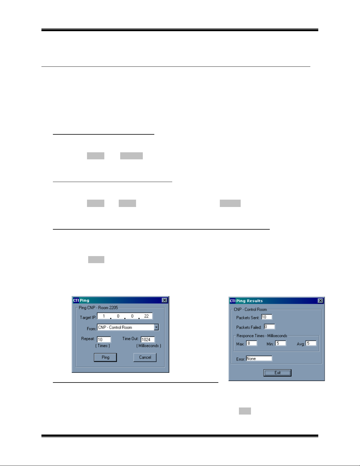
Launch EtherPlug. (See
Right-click on the first
selection. The “
Ping
Click
From the “
message time) for this member.
Ping the remainder of NCB members (except for the NCB unit connected to the PC on which the
network management tool is being run), recording the “
networks (step 6), the router and control neuron processor portions of each NCB unit
ONWORKS
L
L
ONWORKS
, then
Commission
, then
Ping
to cause the ping to be initiated.
Ping Results
routers:
FINISH
NEXT
” request window will be displayed as shown below (left).
to commission the first router.
” function.
again, then select
Step 3
)
Member Name
” window (shown below right), record the “
network management tool. Once all units have been
Commission
Online
and click
in the Channel Member List, then choose “
FINISH
” time for each
Max:
to commission the device.
” time (maximum round-trip
Max:
” function.
Ping
” from the
D) Update “CUSTOM Channel Delay” in LonMaker for Windows:
•
Right-click on the
“
Properties
•
In the “
is twice that of the largest “Max:” time found in
The installation of the NCB units is now complete.
2. Installation 16
Delay
CUSTOM
”. The “
Channel Properties
” section of the “
(Ethernet) channel created in
” window will be displayed.
Channel Properties
” window, choose “
Step 7C
. Then Click
Step 2A
above. In the drop-down list, click
Specify”
OK
, and enter a value that
.
Page 20

CTI Products, Inc. NCB-EL/FL User Guide
NSTALLING ADDITIONAL
I
Should additional NCB units need to be installed after the initial installation has been completed, use one of the
two following sequences:
If using Multicast IP Address Mode:
1. Add the new NCB units to the network management tool per
2. Start EtherPlug and edit the IP Parameters for the new NCB units per
3. Download IP Parameters to
4. Physically install all new NCB units into the IP Network per
5. Commission the Routers and Control Neuron Processors per
timing to the new NCB units and adjust the Custom Channel Delay if necessary.
If using Unicast/Replicated IP Address Mode:
1. Add the new NCB units to the network management tool per
2. Start EtherPlug and edit the IP Parameters for the new NCB units per
3. Download IP Parameters to
4. Per
5. Exit EtherPlug.
6. Physically install the new NCB units into the IP network per
7. Commission the new NCB Routers and Control Neurons per
8. Restart EtherPlug and, per
Step 5
above and using the Serial Port, re-download IP Parameters to the Central Site NCB unit (if
using Central Site Mode), or to the NCB unit whose
network interface on the PC used to run the network management tool and EtherPlug.
timing to the new NCB units and adjust the Custom Channel Delay if necessary.
ONWORKS
L
.
This will put all NCB units in sync with the database.
NCB U
NITS AFTER INITIAL INSTALLATION
Step 2
all
new NCB units via the serial port per
Step 6
Step 7
Step 2
all
new NCB units via the serial port per
Step 5
above, re-download
ONWORKS
L
Database
NETWORK port is connected to the
Step 6
Step 7
parameters to
above.
Step 3
Step 5
above.
above. Check the maximum Ping
above.
Step 3
Step 5
above.
above. Check the maximum Ping
and
above.
and
above.
Channel
Step 4
Step 4
above.
above.
members via
2. Installation 17
Page 21
CTI Products, Inc. NCB-EL/FL User Guide
3. N
ONFIGURATION OBJECT
C
ETWORK VARIABLE
All commands sent to the NCB module are carried on the
the form of Network Variables bound to the Control Neuron processor inside the
NCB module (connected to
the network variables associated with the Configuration Object.
These network variables are not used in a typical application, but are
documented here for specific cases requiring them.
The Configuration Object is used to control and monitor IP/Ethernet functions of the NCB-Etherlon and NCBFiberlon. Command functions include issuing either a ping or a router service pin request. Status and reporting
functions include ping results, MAC address, and product name.
Side A
of the internal router). This section details
(NV) C
ONTROL
ONTALK
L
network in
This Section
contains details
of Network
Variables and
Bindings
Network Variables
Pulse Router Pin (Input)
C Language Syntax
network input SNVT_switch nviPulseRtr;
Usage
This input network variable requests the toggling of the RSVC (Router Service) pin. This in turn
sends a broadcast message on the
router core module with their Neuron ID numbers.
Valid Range
ONWORKS
L
network identifying the Neurons in the NCB’s
Value Pulse Router Pin
Off Disabled
On Enabled
Default Value
Off (Disabled)
Product Name (Output)
C Language Syntax
network output SNVT_str_asc nvoProductName;
Usage
This output network variable contains an ascii string identifying the product.
When Transmitted
Unsolicited at power-up and reset, or when polled.
3. Network Variable (NV) Control 18
Page 22

CTI Products, Inc. NCB-EL/FL User Guide
Ping Request (Input)
C Language Syntax
typedef struct U_PING_REQ
{
unsigned char ip[4]; 4 byte IP address
unsigned char rpt; repeat count
unsigned short t_out; time-out (ms)
16 bits (2 bytes)
0; required zero
}
Usage
This input network variable structure requests an IP ping of the specified IP address. The Repeat
Count specifies the number of pings issued and must have a value between 1 and 255. The Timeout parameter specifies the duration to wait for a ping response from a device. The last parameter
must be the numeral zero.
Ping Results (Output)
C Language Syntax
typedef struct U_PING_STATUS
{
U_PING_REQ request; echoes Ping Request info
4 byte IP address
repeat count
time-out
required zero
unsigned char n_tx, n_fail;
number of actual ping
transmissions and failures
unsigned short mx, mn, avg, err;
ping response times
(maximum, minimum, average,
and 16 bit error code)
}
Usage
This output network variable structure contains the Ping Request information such as IP address,
repeat count, and time-out. It also reports the actual number of ping transmissions and number of
ping response failures. Finally, ping response times are reported in terms of maximum, minimum,
and average. An error code is also returned.
When Transmitted
On Ping Request.
MAC Address (Output)
C Language Syntax
typedef struct MacAddress
{
unsigned char mac[6]; 6 byte MAC address
}
Usage
This output network variable contains 6 decimal bytes representing the MAC address.
When Transmitted
Unsolicited at power-up and reset, or when polled.
3. Network Variable (NV) Control 19
Page 23

CTI Products, Inc. NCB-EL/FL User Guide
4. E
RINTING INFORMATION FROM ETHERPLUG
P
PDATING FIRMWARE IN THE
U
MPORTING/EXPORTING ETHERPLUG CONFIGURATION DATA
I
THERPLUG ADDITIONAL FUNCTIONS
Basic usage of the EtherPlug configuration software is described in S
covers additional features of EtherPlug not described in S
File – Print
The
window) or detailed member information (from the View Details window) either directly to a printer, or to the
default Windows editor.
File – Flash Loader
The
This is possible on NCB units of revision 200 or greater. Contact CTI Products technical support should the
firmware need upgrading.
Import/Export – Export File
The
configuration data in a file outside the LNS database to be used by EtherPlug in standalone mode, or when
transporting the EtherPlug data from one LNS database to another LNS database.
Import/Export – Import File
The
“.el” file extension.
File – Print to File
and
function is used to update the firmware in the NCB-Etherlon or NCB-Fiberlon unit.
functions can be used to print Channel information (from the main
NCB U
function is used (only in LNS Plugin Mode) to save the EtherPlug
function is used to import EtherPlug data from an
NIT
ECTION
ECTION
2.
2 of the manual. This section
ETHERCON
data file with a
THER RIGHT-CLICK MEMBER FUNCTIONS
O
Other functions available on the menu presented after right-clicking on a member name are as follows:
• View Details
for that unit.
• Rename Member & Delete Member
• Wink, Pulse Router Service Pin, Soft Reboot
: Shows the Ethernet/IP data as stored in the NCB unit compared to that in the database
: Allowed only in Standalone mode.
: Allowed only in LNS Plugin mode.
4. NCB Plug-In 20
Page 24

CTI Products, Inc. NCB-EL/FL User Guide
PPENDIX
A
PPENDIX
A
ACTORY DEFAULT CONFIGURATION
A. F
Control Neuron Processor
Restoring Factory Default Communication Parameters
If the Control Neuron Processor or router module communication parameters are overwritten by a network
management tool, they can be restored as follows:
•
Press the “RESET” button on the front of the NCB unit
•
After the “ERR” LED goes off, press the “RESET” button a second time.
The Control Neuron communication parameters are now restored to factory defaults.
IP Address Parameters
The units are factory programmed as follows:
•
IP Address: Unique address based on MAC address of module
•
IP Address Mode: Multicast
•
IP Multicast Address: 224.000.001.016
•
Subnet Mask: 255.255.255.0
Router
The router portion of the NCB module may be configured for various operational characteristics. The factory
default configuration is as a
ports described in section “1. I
subnet/node, or group destination address of the message. Other algorithms, can be selected using standard
ONWORKS
L
network management tools such as the LonBuilder, LonMaker, or LNS.
repeater
NTRODUCTION
, where all messages entering the NCB module (via any of the three data
” are simply passed through, regardless of the domain,
Further details of router operation and configuration are contained in the Echelon document entitled
ONWORKS
"
L
Router User's Guide", Echelon part number 078-0018-01B.
Address Assignments
The router inside the NCB module contains two Neuron chips, each with its’ own subnet/node number
assignment. The default factory configuration of the router Neurons is subnet 255 node 126 and subnet 255
node 127. If any other nodes in the system to which the NCB is connected are configured with either of these
subnet/node addresses, the router should be reconfigured to different addresses using any standard network
management tool. The Control Neuron processor default address setting is subnet 255 node 1.
Buffer Configuration
The NCB module utilizes buffers to store incoming messages and route them out to other ports. The
configuration of these buffers (the number of bytes in each buffer as well as the number of buffers) determine
the maximum size message that can be passed and the performance of the NCB module under conditions of
bursty traffic. In the standard configuration, the NCB router restricts the maximum size message that can be
passed to a length of 40 to 50 bytes of user data, depending on the addressing overhead in the packet.
Technical Note TN010 discusses the topic of buffers and buffer sizes in detail, and should be referenced if
messages to be passed through the NCB module could exceed the maximum default size.
Appendix A. Factory Default Configuration 21
Page 25

CTI Products, Inc. NCB-EL/FL User Guide
Querying, Defaulting, and Unconfiguring Router Configuration using SETRTR.EXE
The SETRTR.EXE DOS utility provided with each NCB can be used to query the router for its current
configuration, force the router to certain default states, or force the router to
will be installed with the
unconfigured
configured).
Refer to Technical Note TN025 for more information on configuration of the router with standard network
management tools such as LonBuilder, LonMaker, LNS, and others.
The SETRTR program requires a network interface to be connected to the personal computer. This network
interface can be an Echelon SLTA, PCLTA, PCNSS, or any other device conforming to Echelon network
interface standards. Network interface driver software must be loaded in the personal computer and configured
with a device name (typically "LONn" where n is a number). Documentation that is provided with the network
interface device details how to install the unit and driver software. The network interface device must contain a
network transceiver compatible with the network transceiver in the NCB module to be controlled.
After the network interface and its software driver are properly configured on the personal computer, connect
its’ network port to the front panel “NETWORK” connector on the NCB.
mode before being installed into the system (this step is mandatory if redundant routers are to be
NOTE: If you are using the PCLTA card as a network interface and the NCB is not
performing the commands as expected, the PCNSS has probably not been configured for
network interface mode. See Technical Note TN024 for information on configuring the
PCNSS card into network interface mode.
configured
router algorithm, it is highly recommended that the router module is set to
unconfigured
mode. If the router
Querying an NCB’s Router for its Current Configuration
Start the SETRTR program with the following command line:
SETRTR [-d
devicename
where
(typically "LON1" or "LON2"). If this parameter is omitted, the default name of LON1 is used.
The -L parameter instructs SETRTR to List the current configuration of the router module.
After the signon message appears, press the “RSVC” button on the front of the connected NCB module.
SETRTR will report the current router configuration to the screen.
Returning an NCB’s Router to Factory Default Configuration
Start the SETRTR program with the following command line:
SETRTR [-d
devicename
where
(typically "LON1" or "LON2"). If this parameter is omitted, the default name of LON1 is used.
The -F parameter instructs SETRTR to set the RTR-10 to full Factory defaults, including router algorithm,
domain tables, and buffer settings.
After the signon message appears, press the “RSVC” button on the front of the connected NCB module.
SETRTR will send the required messages to the router and exit. Press the “RESET” button on the front of the
NCB module to complete the reconfiguration.
Setting an NCB’s Router to Unconfigured Mode
Start the SETRTR program with the following command line:
SETRTR [-d
devicename
is the name assigned to the network interface on the command line of the device driver
devicename
is the name assigned to the network interface on the command line of the device driver
devicename
] -L <cr>
] -F <cr>
] -U <cr>
The -U parameter instructs SETRTR to set both sides of the NCB’s router to
After the signon message appears, press the “RSVC” button on the front of the connected NCB module.
SETRTR will send the required messages to the router and exit.
Appendix A. Factory Default Configuration 22
Unconfigured
mode.
Page 26

CTI Products, Inc. NCB-EL/FL User Guide
PPENDIX
A
OUNTING OPTIONS
B. M
Wall mount and EIA 19” rack mount kits are available as options for the NCB from CTI Products, Inc. The
wall mount kit includes brackets to allow a single NCB module to be mounted to any flat surface. The rack
mount kit includes an adapter allowing up to three NCB modules to be mounted in a single rack unit height.
Rack Mount Option
The rack mount option allows up to three NCB modules to be mounted in a one rack unit height (1.75 inches) of
a standard 19 inch rack. The modules are mounted in the rack plate by removing its’ front bezel and
remounting the module into the rack plate. Figure 7 shows an exploded view of the rack mount installation.
The top diagram shows the front view of the bracket with one module installed. The bottom two diagrams show
a side view of the module installation into the rack adapter and rack adapter installation into the rack,
respectively.
NETWORK
IN
NETWORK OUT
NCB
NETWORK COMBINER
ETH TX
CSVC RSVC
WINK
ETH RX
ASYNC
1234
ERR
ACT
PWR
5
9876
RESET
FACEPLATE
SPACER
CA-80374-100
Figure 7 NCB Module Rack Mounting
Appendix B. Mounting Options 23
Page 27

CTI Products, Inc. NCB-EL/FL User Guide
To attach a module to the rack adapter, and then mount the rack adapter into the rack, follow the steps below.
WARNING
Do not allow the PC board to slide out of the housing when the front panel is removed. If it does,
DO NOT
damage the unit, causing the unit to malfunction when powered on. Doing so will void the unit’s
warranty.
slide the PC board back into the housing from the front of the module. Doing so may
Rack Mounting Instructions
Step Operation
1 Remove the front panel from the module, including the bezel, by removing the two
Philips head screws in the faceplate. The bezel is not used when rack mounting the
module.
2 Position the module behind the rack adapter, lining up the holes in the rack adapter with
the front panel screw holes on the module.
3 Position the front panel in front of the rack adapter, lining up the front panel with the
module.
4 Fasten the front panel and module to the rack adapter with the Philips head screws that
were previously removed.
5 Position the rack adapter into your rack, lining up the four mounting holes of the rack
adapter with mounting holes in the rack frame.
6 Position the two spacers in the front of the rack adapter, aligning the cutouts in the
spacers with the holes of the adapter.
7 Install mounting screws (customer provided) into the rack.
When the module’s front panel is removed, do not allow the PC board to slide out of the housing. If the PC
board does slide out of the housing, you must follow the steps below to replace the PC board in the housing.
DO NOT RE-INSTALL THE PC BOARD FROM THE FRONT OF THE HOUSING !
Re-Installing a PC Board in its housing
Step Operation
1 From the front of the module, slide the PC board out of the housing.
2 Remove the back panel of the module.
3 From the rear of the module, slide the PC board back into the housing (there are
markings on the PC board to indicate which edge to insert into the rear of the housing
first).
4 Install the back panel of the module.
Appendix B. Mounting Options 24
Page 28

CTI Products, Inc. NCB-EL/FL User Guide
Wall Mount Option
The wall mount option allows an NCB module to be mounted to any flat surface. The NCB module has four
screw holes on the bottom. Simply attach the two mounting plates to the bottom of the module using the four
flat-head screws provided with the wall mount kit. This assembly is then attached to the flat surface with userprovided fasteners. Figure 8 shows a dimensioned view of the wall mount installation.
OR
8
7
LINE
6
for connectors.
Allow room on ends
TOP VIEW
6.130
6.700
Allow room on ends
for connectors.
5
4
3
OH
OPTION A
2
1
CD
ON
RSVC
AUDIO
CSVC
CMD
DC IN
NETWORK
NETWORK COMBINER
ACT
NCB
ERR
RESET
PWR
OR
QTY 4
2
QTY 2
1
1.980
3.500
SIDE VIEW
NOTE:
THE NUMBERS ON THIS DRAWING REFER TO THE ITEM NUMBERS
ON THE CORRESPONDING BILLS OF MATERIAL FOR THIS ASSEMBLY.
1.980
Provided by installer.
QTY 4 NO. 8 SCREWS OR OTHER
APPROPRIATE HARDWARE.
1.642
TITLE
APPLICATION
24 VDC
100 mA
ETL APPRO
BOTTOM VIEW
Products Inc.
WON NCB SIZE "B" WALL MOUNT KIT
WON PRODUCTS
Industry
Canada
TO PREVENT DAMAGE TO THE CIRCUIT BOARD.
USE ONLY 6-32 X 1/4" LONG
FLAT HEAD SCREWS TO ATTACH THE
WALL MOUNT BRACKET TO THIS UNIT.
CAUTION!
WALL MOUNT BRACKET TO THIS UNIT.
FLAT HEAD SCREWS TO ATTACH THE
USE ONLY 6-32 X 1/4" LONG
TO PREVENT DAMAGE TO THE CIRCUIT BOARD.
CAUTION!
SHEET OF
1 1
NONE
DRAWING NUMBER
DRAWN BY
CFA
DATE
APPROVED BYSCALE
RKK
DATE
11-22-96
11-22-96
Figure 8 NCB Module Wall Mounting
CAUTION
Be sure to use the flat head screws provided with the wall mount kit. If you are not using the wall mount
kit from CTI Products, Inc., make sure that the screws do not protrude into the enclosure more than 0.125
inches from the bottom surface of the module.
Using a longer screw that touches the PC board inside the module may damage the module. Doing so will
void the unit’s warranty.
Appendix B. Mounting Options 25
Page 29

CTI Products, Inc. NCB-EL/FL User Guide
PPENDIX
A
ONNECTOR DETAILS
C. C
DC IN Connector
Connector type: 2.5 x 5.5 mm coaxial
Mating Connector: Switchcraft 760 or equivalent
Connector pinout: CTI Products, Inc. standard power
supply is wired with center pin positive,
NCB module can accept either pin
positive, polarity routing is provided
internal.
NETWORK Connectors
RJ-45 Connectors:
Pins 1 and 2 of both RJ-45 connectors as well as the screw-terminal connector
are all wired in parallel. The dual RJ-45 connector designates "IN" and "OUT".
These designations apply only to DC power that is passed down unused pairs of
the 4 pair network cable. The two pins carrying the network pair are straightthrough.
Connector Type: Standard RJ-45 telephone connector, 8 position 8
contact.
DC IN
Front View
+-
Polarity
NETWORK OUTIN
12345678
Pin Function Notes
1 Network Network connection is NOT polarity sensitive
2 Network Pins 1,2 of IN and OUT connectors tied parallel
3 No Connection Pin 3 of IN and OUT connectors tied together
4 No Connection Pin 4 of IN and OUT connectors tied together
5 No Connection Pin 5 of IN and OUT connectors tied together
6 No Connection Pin 6 of IN and OUT connectors tied together
7 No Connection Pin 7 of IN and OUT connectors tied together
8 No Connection Pin 8 of IN and OUT connectors tied together
2-Position Screw-Terminal:
Mating Connector: Weidmuller 128176
Pin Function
1Network
2Network
NETWORK
1 2
Appendix C. Connector Details 26
Page 30

CTI Products, Inc. NCB-EL/FL User Guide
SMX Transceiver units:
SMX network connections are described in the documentation with the SMX transceiver.
Ethernet Connectors
10BaseT Connector: AUI Connector:
Connector type: Standard RJ-45 female. Connector type: Standard D-
Subminiature 15 pin female.
Pin Function
1 Ethernet TX
2 Ethernet TX
3 Ethernet RX
4N/C
5N/C
6 Ethernet RX
7N/C
8N/C
Pin Function
1 Chassis Ground
2 Collision
3 Ethernet TX
4 Chassis Ground
5 Ethernet RX
6 Signal Ground
7N/C
8N/C
9 Collision
10 Ethernet TX
11 Chassis Ground
12 Ethernet RX
13 +12V
14 Chassis Ground
15 N/C
NETWORK
2 1
ASYNC Connector
When this port is connected to a PCs serial port, the EtherPlug program can be used to configure the IP address
parameters.
Connector type: Standard D-Subminiature 9 pin male.
Pin Function
1 Data Carrier Detect
2RX
3TX
4 Data Terminal Ready
5 Signal Ground
6 Data Set Ready
7 Clear to Send
8 Request to Send
9N/C
Appendix C. Connector Details 27
Page 31

CTI Products, Inc. NCB-EL/FL User Guide
PPENDIX
A
ROUBLESHOOTING
D. T
Table D1
If the PWR LED . . .
Is always illuminated. Normal operation indicating that NCB unit
Does not illuminate. NCB unit is not receiving DC input power. Check for proper voltage at “DC IN”
REASON CORRECTIVE ACTION
Go to next Table.
is receiving proper DC input power.
connector (10-32VDC).
Table D2
If the ERR LED . . .
Is always off. Normal operation indicating no error
Occasionally blinks on, then
off.
Flashes slowly, at a rate of
once every 2 seconds.
Flashes quickly, at a rate of
once every second.
Is always illuminated. Router module, or Control Neuron
REASON CORRECTIVE ACTION
Go to next Table.
condition was detected.
Normal operation when “CSVC” button or
“RSVC” button is pressed.
The Router Neurons are unconfigured. Use a network management tool to
The Control Neuron Processor detects
missing IP address information.
Processor, or Microprocessor is not
functioning.
Go to next Table.
‘Replace’ or ‘Commission’ router,
or
Use NODEUTIL to change the
mode/state to ‘Configured’ and ‘Online’,
or
Use SETRTR –F to configure the
router to Factory default conditions
(Repeater Mode).
Use EtherPlug to update the IP address
parameters. (See Installation section
for instructions.)
Call CTI Products, Customer Support (+1-
513-595-5900), to arrange to return
unit for evaluation/repair.
Table D3
If the ETH TX LED (on
local NCB) . . .
Occasionally blinks on, then
off.
Does not illuminate when
“RSVC” button on
NCB is pressed.
local
Appendix D. Troubleshooting 28
REASON CORRECTIVE ACTION
Normal operation indicating a message
packet has been transmitted from the
Ethernet port.
Ethernet port is not terminated correctly to
the IP network.
Go to next Table.
a. Verify that OPTION switch positions 7
and 8 are set correctly for the Ethernet
connector being used. See
Installation section.
b. Verify that the cable from NCB
Ethernet port is terminated correctly to
IP network. Check the ‘connection’
LED that is found near each port on
most IP interconnect devices.
c. Verify that the correct cross or straight-
through cable is being used. See
“Appendix F. IP Addresses”.
Step 6A
in
Page 32

CTI Products, Inc. NCB-EL/FL User Guide
Table D4
If the ETH RX LED (on
local NCB) . . .
Occasionally blinks on, then
off.
Does not illuminate when
“RSVC” button on
NCB is pressed.
remote
REASON CORRECTIVE ACTION
Normal operation indicating a message
packet has been detected on the IP
network.
1. Ethernet port is not terminated correctly
to the IP network.
2. If Unicast/Replicated addressing mode is
being used, IP addresses for local and
remote NCB are not compatible.
3. If Multicast addressing mode is being
used, IP network routers or switches are
not configured properly.
Go to next Table.
1a. Verify that OPTION switch positions 7
and 8 are set correctly for the Ethernet
connector being used. See
Installation section.
b. Verify that the cable from NCB
Ethernet port is terminated correctly to
IP network. Check the ‘connection’
LED that is found near each port on
most IP interconnect devices.
c. Verify that the correct cross or straight-
through cable is being used. See
“Appendix F. IP Addresses”.
2a. Verify that portion of IP addresses
identified by Subnet Mask for both
local and remote NCBs are identical.
3a. Verify that IP routers and switches
have Multicast mode enabled.
b. Verify that IP routers are programmed
to pass the IP multicast address of the
NCB-Etherlon.
c. Verify that IP routers are programmed
to pass the NCB-Etherlon multicast
port numbers of 1100 (destination port)
and 1283 (source port).
Step 6A
in
Appendix D. Troubleshooting 29
Page 33

CTI Products, Inc. NCB-EL/FL User Guide
Table D5
If the ACT LED (on local
NCB) . . .
Occasionally blinks on, then
off.
Does not illuminate when
ORKS
remote
nodes
nodes
“RSVC” button on
NCB is pressed.
Does not illuminate when
local
LONW
are transmitting messages.
Does not illuminate when
remote
ONWORKS
L
are transmitting messages.
REASON CORRECTIVE ACTION
Normal operation indicating a message
packet has passed through the router
module of the NCB.
ONWORKS
1.
L
remote
Service Pin message from
NCB is not reaching the
local
NCB.
2.
1.
ORKS
LONW
remote
local
ONWORKS
L
Service Pin message from
NCB is not passing through the
router module.
message packets from
nodes are not passing through the
router module.
ONWORKS
1.
2.
L
remote
remote
LONW
remote
message packets from
nodes are not passing through the
router module.
ORKS
message packets from
nodes are not reaching the local
NCB.
3.
L
remote
local
ONWORKS
message packets from
nodes are not passing through the
router module.
local
local
Go to next Table.
1a. Verify that “ACT” and “ERR” LED’s
remote
on
NCB flash once. If not,
return remote unit for
evaluation/repair.
b. Verify that “ETH TX” LED flashes on
the remote NCB and that “ETH RX”
LED flashes on the local NCB.
2a. Place the
remote
router in Repeater
mode and verify that the
LED illuminates when “RSVC” button
remote
on
NCB is pressed.
b. If ‘2a’ is ok, re-commission the
NCB router.
c. If ‘2a’ is not ok, swap either the local
or remote unit with a known-good-unit
to determine the faulty unit.
1a. Verify the connection between the
local
ONWORKS
L
nodes and the
NCB.
b. Place the
local
router in Repeater mode
and verify that its “ACT” LED
illuminates when local
nodes are transmitting messages.
c. If ‘1b’ is ok, re-Commission the
NCB.
d. If ‘1b’ is not ok, return the
unit for evaluation/repair.
1a. Verify the connection between the
remote
remote
ONWORKS
L
NCB.
b. Verify that “ACT” LED on
NCB illuminates when
ONWORKS
L
nodes are transmitting
messages.
c. Place the
remote
router in Repeater
mode and verify that its “ACT” LED
illuminates when
remote
nodes are transmitting messages.
d. If ‘1c’ is ok, re-commission the remote
router.
e. If ‘1c’ is not ok, return unit for
evaluation/repair.
2. See this Table above and verify step
“ACT” LED “Does not illuminate
when “RSVC” button on
is pressed”.
3. See this Table above and verify step
“ACT” LED “Does not illuminate
when “RSVC” button on
is pressed”.
local
“ACT”
local
ONWORKS
L
local
NCB
nodes and the
remote
remote
ONWORKS
L
remote
remote
local
local
NCB
NCB
Appendix D. Troubleshooting 30
Page 34

CTI Products, Inc. NCB-EL/FL User Guide
Table D6
Miscellaneous:
Cannot communicate with
Control Neuron Processor
local
of
NCB when using
NODEUTIL.
Cannot communicate with the
Control Neuron Processor
of local NCB.
Cannot commission the
Control Neuron
Processor when using
LonMaker for
Windows.
REASON CORRECTIVE ACTION
1. In Bridge or Configured modes, router
neurons and network interface are not in
the same domain.
2. In Repeater mode, the network interface
may be defective.
1. In Bridge or Configured modes, the
Control Neuron, the router neurons, and
the network interface are not all in the
same domain.
2. In Repeater mode, the Control Neuron
and network interface are not in the same
domain.
Incorrect external interface definition
(.xfb or .xif file) was specified when
1. Verify that NODEUTIL can
communicate with another
node.
2a. Place the local router in Repeater mode
and verify that communications is
possible, or
b. Use NODEUTIL to change the
network interface Domain to match the
router neurons’ domains.
1. Place the local router neurons in
Repeater mode.
2. Change the network interface Domain
to match the Control Neuron domain.
Use NCBEL20 for Version 2 NCB-
Etherlon or NCB-Fiberlon.
commissioning node.
ONWORKS
L
Appendix D. Troubleshooting 31
Page 35

CTI Products, Inc. NCB-EL/FL User Guide
PPENDIX
A
PECIFICATIONS
E. S
NCB-Etherlon and NCB-Fiberlon
DC Power Input:
Size:
7.5” D x 5.6” W x 1.6” H
Operating Temperature:
Humidity:
Mounting:
Configuration:
Integral Router
Ethernet IP Parameters
Transceivers Supported:
ONWORKS
L
10 to 32 VDC, unregulated (10BaseT)
0 to 60 °C
10-95% non-condensing
FTT-10A, TPT/XF-78, TPT/SF-1250, SMX
15 to 32 VDC unregulated (AUI)
5 watts maximum without SMX transceiver
10 watts maximum with SMX power line transceiver
Desktop with integral non-slip feet
Wallmount or 19” rack mount with optional adapters
Factory default router mode is set to Repeater. Configured or Bridge mode
can be selected using standard
capable of configuring routers.
Using supplied EtherPlug (stand-alone Windows program or LNS
application plug-in)
ONWORKS
L
network management tools
Ethernet
IP Addressing Modes:
IP Transport:
Maximum
ONTALK
L
Packet Size:
10BaseT, AUI (10BaseFL for NCB-Fiberlon)
Unicast/Replicated, Multicast
UDP
66 bytes (factory default router configuration)
255 bytes (maximum with software re-configuration)
Appendix E. Specifications 32
Page 36

CTI Products, Inc. NCB-EL/FL User Guide
PPENDIX
A
F. IP A
DDRESSING
Conventions
Any node connected to an IP (Internet Protocol) network must be identified with a unique 32-bit address. These
32-bit addresses are commonly written
because each decimal number represents 8 bits) separated by decimal points. Each octet can be a number from
1 to 255. For example, 131.9.1.2 is a valid IP address. The IP address assigned to a network device is
commonly called the
stations (also called hosts or nodes) on the network.
The NCB-Etherlon and NCB-Fiberlon modules are provided from the factory with default addressing to allow
simple “quickstart” testing by connecting them back-to-back. See “A
ONFIGURATION
C
Host IP Address
”.
in dotted decimal
. By having unique addresses on a network, you can identify individual
notation as four decimal numbers (referred to as octets
PPENDIX
ACTORY DEFAULT
A. F
IP Address Classes
There are five types of IP addresses. Three are associated with networks – Class A, B, and C.
• Class A
on a single IP network. The first octet is between 1 and 126. (127 is reserved for loopback and is used
for internal testing on the local machine.)
• Class B
• Class C
Class D
•
• Class E
An IP address consists of two parts – one part identifies the network, and one part identifies the host (or node).
The NetID portion of the IP address identifies the physical network segment. The HostID portion of the IP
address identifies the node within the network segment. The following table lists the capacities of each IP
address and the bits used as NetID and HostID.
addresses are for networks that have a large number of hosts, up to a maximum of 16,777,216
addresses are for medium-sized networks. The first octet is between 128 and 191.
addresses are for small networks, up to 255 hosts. The first octet is between 192 and 223.
addresses are reserved for multicasting and the first octet is between 224 and 239.
addresses (240 to 255) are reserved and should not be used.
IP
Class
A 8 126 24 16.7 million 1-126
B 16 16,000 16 65,000 128-191
C 24 2 million 8 254 192-293
Net ID
(Beginning Bits)
# of
Networks
Host ID
(Ending Bits)
# of Hosts or
Subnets
1st byte
Range
Subnetting using Subnet Masks
A portion of the host bits can be used to “subnet the network”. The subnet mask identifies the “NetID” and
“HostID” portions of the IP address in a bitwise fashion. The mask is constructed by placing a “1” in any bit
that is part of a subnetwork address. So subnet mask bits that are SET define the NetID, and CLEARED subnet
mask bits define the HostID.
A subnet mask of 255.255.255.0 defines the NetID as the first three octets, and the HostID as the last octet. For
example, for the address 192.47.73.111 and the subnet mask of 255.255.255.0, the subnetwork can be
identified as 192.47.73.0.
Summary of Important Networking Details
•
A specific “NetID” can exist on only ONE port of ONE IP router.
•
The “NetID” portion of the Host Address and the Gateway Address MUST BE THE SAME.
•
If a functional router (such as a NCB Router) is moved to a different location, its Host IP Address and
Default Gateway IP Address MUST BE CHANGED to match the “NetID” at the new location.
Appendix F. IP Addresses 33
Page 37

CTI Products, Inc. NCB-EL/FL User Guide
IP Addressing modes
Unicast/Replicated
Unicast/Replicated addressing mode allows point-to-point or point-to-multipoint communications in any IP
network. A table of
each containing the IP addresses of the other modules in the group. The maximum number of NCBs that can be
configured into one Unicast/Replicated group is 96.
Target IP Addresses
is configured into each of the NCB-Etherlon™ Routers, the table in
Each NCB is programmed with a
Gateway IP Address
Default Gateway IP Address
. The
Host IP Address
, a list of
Target IP Addresses
, and optionally, a
Default
is the address of the IP router to which the respective
NCB-Etherlon is attached and allows for IP routers or gateways that may exist between NCB-Etherlon units.
Using Unicast/Replicated mode, a single
ONTALK
L
packet entering any of the NCB modules of the group will
be sent out the Ethernet port of that module as multiple Unicast IP messages, one to each of the other NCB
modules in the group.
Multicast
Multicast addressing mode allows efficient point-to-multipoint communications in a network. Each NCB is
assigned a
single
Host IP Address, a multicast Target IP Address
multicast Target IP Address
is assigned to all NCB in the network within the range 224.0.1.0 through
, and optionally, a
239.255.255.255.
A single
sent out the Ethernet port of that module to be received by
ONTALK
L
packet entering any one of the NCB modules results in a
all
other NCB members configured to the same
Multicast IP address.
Multicast addressing mode can be used with a very large number of NCB-Etherlon modules, allowing
combinations of very large number of
ONTALK
L
packet, multicast addressing mode uses far less network bandwidth that Unicast/Replicated.
ONWORKS
L
network. Because only one IP packet is generated for every
Before choosing multicast addressing mode, it is important to determine the following capabilites of the IP
network to which the NCB units will be connected:
•
IP routers must be capable of handling IP multicast traffic.
•
IP routers must have IP multicast enabled
•
IP routers must forward the NCB multicast port numbers of 1100 (destination port) and 1283 (source
port).
Default Gateway IP Address
single
multicast IP packet being
. A
MAC Addresses
Whereas IP uses Logical Addresses to identify a host (node), other protocols use Hardware Addresses called
Media Access Control addresses, or MAC addresses. MAC addresses are set at the factory at time of
manufacture and cannot be changed. (IP addresses can be changed at any time.) A MAC address consists of
six octets, in hexadecimal notation, separated by colons. An example would be: 00:10:EE:00:02:34.
The first three octets in a MAC address identify the manufacturer. In the above example, 00:10:EE identifies
CTI Products as the manufacturer of this device. The last three octets are sequentially assigned by the
manufacturer to form a type of serial number. In this way, no two devices have the same MAC address.
Multicast addressing is also possible using MAC addresses, just as in IP addressing. MAC addresses reserved
for broadcast messages start at: 00:01:5E:00:00:00.
Address Resolution Protocol (ARP)
Since IP uses Logical Addresses at the OSI Network Layer (Layer 3) and Ethernet uses MAC addresses at the
OSI Data Link Layer (Layer 2), Address Resolution Protocol is used whenever IP is used over the Ethernet.
ARP is needed to convert an IP address to a MAC address. The client then stores this resolved address for a
period of time in its ARP cache. An ARP cache is a lookup table, typically in a router, that will store a quantity
of resolved addresses for devices that it must communicate with.
Appendix F. IP Addresses 34
Page 38
CTI Products, Inc. NCB-EL/FL User Guide
When a message is destined for an IP address whose MAC address has not yet been resolved, an ARP
REQUEST is sent from the local host as a broadcast message, asking for MAC identification. A remote host
with the IP address in question generates an ARP RESPONSE. This ARP RESPONSE contains the requested
MAC address. The local host receives the message, and places the IP Address and the matching MAC Address
in its ARP Cache. The original message is then sent using the MAC Address found previously. Any additional
messages to this remote IP address will be sent using the MAC address found in the local host’s ARP cache.
Ethernet 10BaseT Cables
When connecting two IP devices together, either a straight-through cable or a crossover cable may be required.
If interconnecting similar devices, then a crossover cable is needed. Examples would be interconnecting two
NCB routers, or two IP routers, or two hubs, or two computers. Generally, if the two devices are both Layer 3
devices, then a crossover cable is required. Routers operate at Layer 3. Similarly, if the two devices are Layer
1 or 2 devices, they would also require a crossover cable. Bridges, switches, and Network Interface Cards
(NIC) operate at Layer 2, and hubs, repeaters, and concentrators operate at Layer 1.
If interconnecting dissimilar devices, then a straight-through cable is needed. Dissimilar devices would involve
one Layer 3 device and a Layer 1 or Layer 2 device.
The following table summarizes devices in each layer.
Layer 3 Layer 2 Layer 1
IP Router Bridge Hub
NCB Router Switch Repeater
NIC Concentrator
The following table lists the connections for a straight-through cable.
Standard End Standard End
Signal Name Wire Color Pin Pin Wire Color Signal Name
TD+ White/Orange 1
TD- Orange 2
RD+ White/Green 3
Not used Blue 4
Not used White/Blue 5
RD- Green 6
Not used White/Brown 7
Not used Brown 8
The following table lists the connections for a crossover cable.
Standard End Crossover End
Signal Name Wire Color Pin Pin Wire Color Signal Name
TD+ White/Orange 1
TD- Orange 2
RD+ White/Green 3
Not used Blue 4
Not used White/Blue 5
RD- Green 6
Not used White/Brown 7
Not used Brown 8
ÅÆ
ÅÆ
ÅÆ
ÅÆ
ÅÆ
ÅÆ
ÅÆ
ÅÆ
ÅÆ
ÅÆ
ÅÆ
ÅÆ
ÅÆ
ÅÆ
ÅÆ
ÅÆ
1 White/Orange TD+
2 Orange TD3 White/Green RD+
4BlueNot used
5 White/Blue Not used
6 Green RD7 White/Brown Not used
8BrownNot used
3 White/Green RD+
6 Green RD1 White/Orange TD+
5BlueNot used
4 White/Blue Not used
2 Orange TD8 White/Brown Not used
7BrownNot used
Appendix F. IP Addresses 35
Page 39

CTI Products, Inc. NCB-EL/FL User Guide
NDEX
I
A
Address Resolution Protocol.........................
B
Bridge........................................................................ 3
Broadcast ................................................................ 35
Buffer Configuration............................................... 21
C
Configured router................................................ 3, 22
Connector................................................................ 26
Control Neuron Processor......................... 5, 9, 16, 21
D
Domain.......................................................... 3, 21, 22
Dotted Decimal ....................................................... 33
E
ERR LED............................................................ 5, 21
Ethernet
EtherPlug......................................................iii, 10, 20
Factory Default Parameters..................................... 21
Front Panel................................................................ 5
connector................................................. 15
F
See
ARP
L
LINE connector......................................................... 2
Logical Address ..................................
ONWORKS
L
M
MAC Address ......................................................... 34
Media Access Control....................
Message Buffer ......................................................... 4
Modem Controller object........................................ 18
Mounting Kit........................................................... 14
Multicast ........................................................... 33, 34
N
NetID ...................................................................... 33
NETWORK connector.............................. 2, 3, 15, 22
Network Management Tool ................................ 5, 21
O
Octets ...................................................................... 33
P
Point-to-Multipoint ................................................. 34
Port Number............................................................ 34
Power Connection................................................... 15
..................................................... 3, 9, 18
See
IP Address
See
MAC Address
G
Gateway Address .............................................. 33, 34
H
Hardware Address..........................
Host IP Address ...................................................... 34
HostID..................................................................... 33
I
Internal router............................................ 3, 5, 18, 21
Internet Protocol...................................................... 33
IP Address............................................................... 34
See
MAC Address
R
Rear Panel ................................................................. 6
Repeater .............................................................. 3, 21
RJ-45................................................................. 15, 26
S
SETRTR.EXE......................................................... 22
Subnet Mask............................................................ 33
Subnet/node......................................................... 3, 21
U
Unicast/Replicated .................................................. 34
Index 36
Page 40

 Loading...