

Page 1

Model NCB-EM
Network Combiner Module
with External Modem
Wide Area Router for LONWORKS® Networks
User Guide # S2-60695-310
68-11220-310
Page 2

CTI Products, Inc. NCB-EM User Guide
Standard Limited Hardware Warranty
LIMITED WARRANTY. Equipment manufactured by CTI Products, Inc. is warranted to be free from defects in material and workmanship for
a period of ONE (1) YEAR from date of shipment to original purchaser. Under this warranty, our obligation is limited to repairing or replacing
any equipment proved to be defective by our inspection within one year of sale to the original purchaser. This warranty shall not apply to
equipment which has been repaired outside our plant in any way, so as to, in the judgment of CTI Products, Inc. affect its stability or reliability,
nor which has been operated in a manner exceeding its specifications, nor which has been altered, defaced, or damaged by lightning.
CUSTOMER REMEDIES. In the event of a defect, malfunction, or failure to conform to specifications established by the seller during the
period shown, the customer shall call CTI Products, Inc. to obtain a Return Authorization Number and return the product or module, shipping and
insurance prepaid. CTI Products, Inc., will then at its option, either repair or replace the product or module and return it, shipping prepaid, or
refund the purchase price thereof. On-site labor at the purchaser's location is not included in this warranty.
EQUIPMENT NOT MANUFACTURED BY CTI Products, Inc. Equipment not manufactured by CTI Products, Inc. is excluded from this
warranty, but is subject to the warranty provided by its manufacturer, a copy of which will be supplied to you upon specific written request.
NO OTHER WARRANTIES. The foregoing constitutes the sole and exclusive remedy of the buyer and exclusive liability of CTI Products,
Inc., AND IS IN LIEU OF ANY AND ALL OTHER WARRANTIES EXPRESSED OR IMPLIED OR STATUTORY AS TO
MERCHANTABILITY, FITNESS FOR PURPOSE SOLD, DESCRIPTION, QUALITY, PRODUCTIVENESS OR ANY OTHER MATTER.
NO LIABILITY FOR CONSEQUENTIAL DAMAGES. WITHOUT LIMITING THE FOREGOING, IN NO EVENT SHALL CTI
PRODUCTS, INC. OR ITS SUPPLIERS BE LIABLE FOR ANY DAMAGES WHATSOEVER (INCLUDING, WITHOUT LIMITATION,
SPECIAL, INCIDENTAL OR CONSEQUENTIAL DAMAGES OR FOR LOSS OF BUSINESS PROFITS, BUSINESS INTERRUPTION,
LOSS OF BUSINESS INFORMATION, OR OTHER PECUNIARY LOSS) ARISING OUT OF THE USE OF OR INABILITY TO USE CTI
PRODUCTS, INC. EQUIPMENT BY PURCHASER OR OTHER THIRD PARTY, WHETHER UNDER THEORY OF CONTRACT, TORT
(INCLUDING NEGLIGENCE), INDEMNITY, PRODUCT LIABILITY OR OTHERWISE, EVEN IF CTI PRODUCTS, INC. HAS BEEN
ADVISED OF THE POSSIBILITY OF SUCH DAMAGES OR LOSSES. IN NO EVENT SHALL CTI PRODUCTS, INC.’S, LIABILITY
EXCEED THE TOTAL AMOUNT PAID BY PURCHASER FOR THE EQUIPMENT GIVING RISE TO SUCH LIABILITY.
Location: CTI Products, Inc
Phone: +1.513.595.5900
Fax: +1.513.595.5983
Web: www.ctiproducts.com
E-mail, Sales: info@ctiproducts.com
Technical Support: lwsupport@ctiproducts.com
i
1211 West Sharon Road
Cincinnati, OH 45240 USA
Page 3

CTI Products, Inc. NCB-EM User Guide
This manual covers NCB units of Revision 300 or higher and NCB/Plug software revision
1.00 or higher. The NCB Unit Revision can be found on the rear of the unit following the
letter “U”. The NCB/Plug software revision can be found on the Help/About screen of the
program. If the revision of the product in hand is greater than that shown above, there may
be additional features supported by the product that are not covered in this manual.
Information contained in this document is subject to change without notice and does not represent a commitment on the part of CTI
Products, Inc.
No part of this manual may be reproduced or transmitted in any form or by any means, electronic or mechanical, including photocopying
and recording, for any purpose without the written permission of CTI Products, Inc.
This manual describes products which include copyrighted CTI Products, Inc. computer programs in semiconductor memory. CTI
Products, Inc. reserves all rights for these programs, including the exclusive right to copy or reproduce the copyrighted computer programs
in any form. No copyrighted computer program contained in products described in this manual may be copied, reproduced, decompiled,
disassembled, or reversed engineered in any manner without express written permission of CTI Products, Inc. The purchase of products
from CTI Products, Inc. shall not be deemed to grant either directly or by implication, estoppel, or otherwise, any license under the
copyrights, patents, or patent applications of CTI Products, Inc., except for the normal non-exclusive, royalty fee license to use that arises
by operation of law in the sale of the product.
Copyright (c) 1995-2001 CTI Products, Inc. All rights reserved
NCB, NCB/EM, and WON are trademarks of CTI Products, Inc.
Echelon, LON, LONWORKS, LONTALK, and Neuron are U.S. registered trademarks of Echelon Corporation.
ii
Page 4

CTI Products, Inc. NCB-EM User Guide
Radio Frequency Emissions and Immunity
This equipment generates, uses, and can radiate radio frequency energy and, if not installed and used in accordance with the instruction manual,
may cause harmful interference to radio communications. Operation of this equipment in a residential area is likely to cause harmful interference
in which case the user will be required to correct the interference at his own expense. Changes or modifications to this unit not expressly
approved by the party responsible for compliance could void the user’s authority to operate the equipment. Limits specified in the standards listed
below are designed to provide reasonable protection against harmful interference when the equipment is operated in a commercial environment.
UNITED STATES: This equipment has been tested and found to comply with the limits for a Class A digital device, pursuant to Part 15 of the
FCC Rules.
CANADA: This Class A digital apparatus meets all requirements of the Canadian Interference-Causing Equipment Regulations.
Cet appareil numérique de la classe A respecte toutes les exigences du Règlement sur le matériel brouilleur du Canada.
EUROPE: This equipment has been tested and found to comform with the following standards: EN60950, EN50082-1, IEC801-2, IEC801-3,
IEC801-4, and EN55022. This equipment complies with the requirements of the following directives: Low Voltage Directive 73/23/EEC, EMC
Directive 89/336/EEC, and 93/68/EEC Harmonization of CE Marking
iii
Page 5

CTI Products, Inc. NCB-EM User Guide
TABLE OF CONTENTS
QUICK-START GUIDE ............................................................................................................................................. 1
1. INTRODUCTION ................................................................................................................................................... 3
WHAT IS AN NCB/EM UNIT? ..................................................................................................................................... 3
REFERENCE DOCUMENTS ........................................................................................................................................... 5
FRONT PANEL ............................................................................................................................................................. 6
REAR PANEL............................................................................................................................................................... 7
2. SETUP AND OPERATION .................................................................................................................................... 9
STEP 1. MOUNTING .................................................................................................................................................... 9
STEP 2. SWITCH SETUP .............................................................................................................................................. 9
STEP 3. ELECTRICAL CONNECTIONS ........................................................................................................................ 11
STEP 4. MODEM CONFIGURATION............................................................................................................................ 13
STEP 5. IMPLEMENTATION IN A NETWORK ............................................................................................................... 14
STEP 6. CONTROLLING THE WAN CONNECTION...................................................................................................... 17
3. NETWORK VARIABLE (NV) CONTROL ....................................................................................................... 19
TYPICAL NV BINDINGS ............................................................................................................................................ 19
MODEM CONTROLLER OBJECT ................................................................................................................................. 20
TELEPHONE DIRECTORY OBJECT .............................................................................................................................. 27
GLOBAL CONTROL OBJECT ...................................................................................................................................... 28
4. NCB/PLUG CONFIGURATION PLUG-IN ....................................................................................................... 30
INSTALLATION .......................................................................................................................................................... 30
ACCESSING NCB/PLUG .......................................................................................................................................... 31
USAGE ................................................................ ................................ ................................................................ ...... 31
APPENDIX ................................................................................................................................................................ 34
APPENDIX A. FACTORY DEFAULT CONFIGURATION ................................................................................................. 34
APPENDIX B. MOUNTING OPTIONS ........................................................................................................................... 36
APPENDIX C. CONNECTOR DETAILS ......................................................................................................................... 39
APPENDIX D. NCB VERSION COMPARISON .............................................................................................................. 41
APPENDIX E. TROUBLESHOOTING ................................................................ ............................................................ 42
APPENDIX F. SPECIFICATIONS .................................................................................................................................. 47
APPENDIX G. MODEM NOTES ................................................................................................................................... 49
APPENDIX H. RING MODE ........................................................................................................................................ 53
INDEX ........................................................................................................................................................................ 55
iv
Page 6

CTI Products, Inc. NCB-EM User Guide
v
Page 7
CTI Products, Inc. NCB-EM User Guide
QUICK-START GUIDE
This Quick Start Guide provides a concise series of steps to get a pair of the NCB modules “up and running” quickly so that
initial operation may be confirmed.
It is important that all LONWORKS devices attached to the “NETWORK” connector of any one NCB module use the same
network transceiver . See “LONWORKS NETWORK TRANSCEIVERS” in section “1. INTRODUCTION”.
In the following steps, identify the two units as “NCB Unit 1” and “NCB Unit 2”.
Switch Settings
Set the switches on the NCB units as follows:
If you are using the leased-line modems (MT2834BL), set the DIP switches on the side of those modems as
BAUD 1 : 7 BAUD 2 : 0 MODE 1 : C MODE 2 : C
OPTION B Switches 1 through 4 : UP
OPTION A Switches 1 through 4 and 6 through 8 : UP
OPTION A Switch 5 : DOWN
follows:
1: DOWN 5: # 9: DOWN 13: UP
2: UP 6: UP 10: UP 14: UP
3: UP 7: DOWN 11: DOWN 15: UP
4: UP 8: DOWN 12: DOWN 16: UP
# Set Switch 5 DOWN on Modem 1 and UP on Modem 2
Module Connection
Connect LonWorks network devices to the “NETWORK” connectors of each NCB unit (both RJ45s and the
terminal strip are in parallel). If using the RJ45 connector(s), connect to pins 1 & 2 (the right-most two pins) and
use caution, as other pins on these connectors carry DC power. On a three pin terminal strip connector (if
present), use the two left-most pins.
Connect the DB25 connector on the modem to the “PORT 1” connector on the rear of the NCB unit using the
cable supplied with the modem.
If using the dial-up modems (MT2834ZDX), connect each modem to a standard analog telephone line or PBX
port. If using the leased-line modems (MT2834BL), connect the “LEASED” or “PRIVATE” connectors on the
rear of each modem together using the telephone cord provided with the NCB unit.
Connect power to the modems (and switch them on), and to the NCB units via the front panel “DC IN” connector.
The units can be powered-up in any sequence. Both NCB Unit “ERR” LEDs will begin to flash.
NOTE: It is normal for the NCB Unit “ERR” LED to flash quickly for up to 30 seconds after power-up
or reset of a fully configured and connected NCB/EM. This indicates that any external modems
configured for use are in process of initializing. A problem is indicated only if the “ERR” LED locks on
or continues to flash for more than 30 seconds after power-up or reset.
If dial-up modems (MT2834ZDX) are being used, the NCB modules are ready for use once the “ERR” LEDs have
stopped flashing and can be given a dialing command. Proceed directly to “STEP 6. CONTROLLING THE WAN
CONNECTION”in section “2. SETUP AND OPERATION”.
If leased-line modems (MT2834BL) are being used, the initialization sequence for each is complete once the
“ERR” LED on the respective NCB unit has stopped flashing (this initialization sequence sets non-volatile
parameters in the modem and must be performed whenever a new modem is installed for use with an NCB unit).
Switch both modems and both NCBs into operational mode as follows:
MODEM DIP Switch 10: change to DOWN
NCB MODE 1, 2 : change to D
Power-cycle the modems and NCB units. The “ERR” LEDs will blink briefly, then stay off and the modems will
automatically begin the training sequence. Within 30 seconds, the “CD” LEDs on both modems will light
indicating a successful connection. The modules are now ready for use. Any LonTalk packets entering one NCB
unit will exit the other and vice-versa. Breaking then restoring the leased-line connection between the modems
will cause the connection to be automatically re-established.
NOTE: If using Leased-Line mode, this quickstart setup includes connecting the modems “back-to-
back” using 2 wire mode and a reduced transmit level. In an actual leased-line installation involving
longer telephone cable lengths, change MODEM DIP Switch 3 to DOWN to configure the modem to
output full transmit power, and set MODEM DIP Switch 16 UP for 2-wire mode or DOWN for 4-wire
mode.
Quick-Start Guide 1
Page 8

CTI Products, Inc. NCB-EM User Guide
Quick-Start Guide 2
Page 9
CTI Products, Inc. NCB-EM User Guide
CA-80070-100
LONWORKS
NODE
LONWORKS
NODE
LONWORKS
NODE
LONWORKS
NODE
NCB
LONWORKS
NODE
LONWORKS
NODE
LONWORKS
NODE
LONWORKS
NODE
NCB
STANDARD
VOICE GRADE
CIRCUIT
BUILDING 1
BUILDING 2
Read this
section to learn
the general
function and
capabilities of an
NCB Router
1. INTRODUCTION
WHAT IS AN NCB/EM UNIT?
The Network Combiner NCB/EMTM Module is a wide-area router with one or
two external modems used for LONWORKS networks. The NCB/EM unit is
used in pairs to connect LONWORKS networks real-time, spanning distances
from building-wide to worldwide.. The communication channel spanning the
distance between local networks can be any analog or digitized analog channel
that is capable of carrying V.34 standard modem signaling. NCB/EM units are
available with modems for standard dial-up Public Switched Telephone Network (PSTN) circuits, 2-wire or 4wire leased lines, microwave channels, PBX circuits, etc. Data transfer between distant networks via an NCB
module pair is "live", delayed only by the transit time through the routers and modem connections.
The NCB module uses router technology so that no custom coding or additional hardware is necessary to
seamlessly connect multiple networks across very large distances. The NCB module is self-contained, easily
configured with standard network management tools, and requires no custom programming or coding changes
in system nodes.
The NCB/EM unit contains a Modem Controller and a Telephone Directory objects
Basic Application
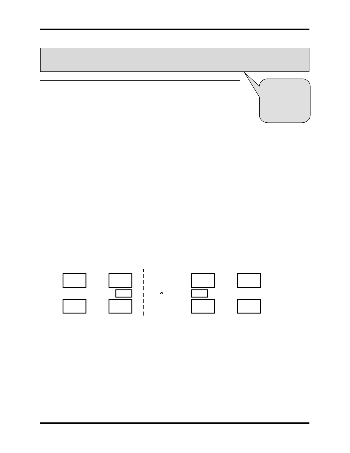
A basic application of the NCB module is where two multi-node LonWorks networks, separated by a distance
beyond the reach of conventional wired media, need to be interconnected, as in Figure 1. This distance could be
across a large building, business campus, city, etc. Using the NCB module, this interconnection is
accomplished using one NCB module local to each network site and a single voice-grade telephone circuit
connecting the two NCB modules. Additional networks can be added to this unified network by simply adding
an NCB module pair per network.
Figure 1 Networks in two buildings connected with NCB modules
LonWorks Network Transceivers
The local LonWorks networks at different sites do not need to use the same network transceiver type. For
example, an FTT-10A network, a TPT/XF-78 network, and a PLT-22 network can all be interconnected by
using pairs of NCB modules with network transceivers matching the local network at each site.
1. Introduction 3
Page 10
CTI Products, Inc. NCB-EM User Guide
LONWORKS
NETWORK
Side
A
ROUTER
LONWORKS
TRANSCEIVER
“DC I N”
Connector
“NETWORK”
Connector
“PORT 1”
Connector
“PORT 2”
Connector
To Modem 1
To Modem 2
Side
B
SMX
TRANSCEIVER
POWER
SUPPLY
CONTROL
NEURON
PROCESSOR
See Appendix H
for Ring Mode
details.
NCB units are available with an option for LonWorks network transceiver type. The ordering code on the rear
of the NCB lists the installed options. This ordering code is of the form: NCB/EM-Txxx-xx, where ‘T’
indicates the transceiver type.
The following LonWorks network transceiver options are available:
A = FTT-10A K = SMX RS485
B = TPT/XF-78 M = SMX PL22
C = TPT/XF-1250 X = None (SMX ready)
Wide Area Network Ports
Normally Point-to-Point connections are made between pairs of NCB’s. A more
fault-tolerant network may be implemented by using the Ring Mode connection
topology.
External Serial Ports
“PORT 1” and “PORT 2” are standard asynchronous serial ports with individually configurable baud rates from
1200 to 115200 bps. An external modem can be connected to each port. “PORT 1” and “PORT 2” pinouts
allow direct connection to a modem via a standard 9 pin to 25 pin cable.
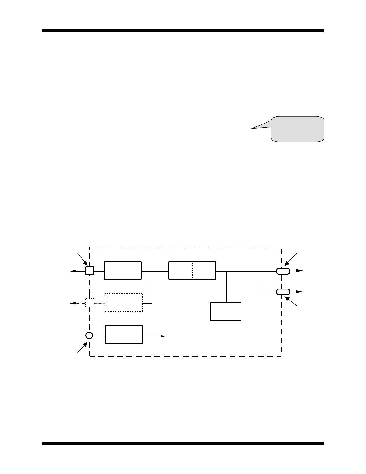
Data Flow
There are three sources of message packets within the NCB module. The first source is the LonWorks
NETWORK connector on the front of the unit. The second is the “PORT” connectors on the rear of the unit.
The third source is the Control Neuron Processor. Message packets originating from any of these sources are
sent to the other two. This message packet flow is shown in the block diagram of Figure 2.
Figure 2 NCB Network Combiner Block Diagram
The “NETWORK” connector attaches to the local LONWORKS network using a compatible transceiver
internal to the NCB module and is associated with Side B of the internal router.
The “PORT” connector attaches to the modem as the link to the NCB unit at the other network site and is
associated with Side A of the internal router.
The Control Neuron Processor allows network management messages to be sent to the NCB module for
connection control and status monitoring and is associated with Side A of the internal router.
1. Introduction 4
Page 11

CTI Products, Inc. NCB-EM User Guide
Document
Source
Reference Number
Message Buffer Configuration
CD ROM or www.ctiproducts.com
Technical Note TN010
Use of External Modems other
than Multitech
CD ROM or www.ctiproducts.com
Technical Note TN011
Using Explicit Messages to
Configure and Monitor Dialing
Parameters of an NCB
CD ROM or www.ctiproducts.com
Technical Note TN022
Using NCBCON to Configure
and Monitor Dialing
Parameters of an NCB
CD ROM or www.ctiproducts.com
Technical Note TN023
Setting the PCNSS Card to
Network Interface Mode
CD ROM or www.ctiproducts.com
Technical Note TN024
SMX Transceiver Installation
CD ROM or www.ctiproducts.com
Technical Note TN025
NCB Installation with Network
Management Tools
CD ROM or www.ctiproducts.com
Technical Note TN026
LonWorks Router User’s Guide
Echelon
078-0018-01B
Router Function
The router contained in each NCB module may be configured as a repeater, bridge, or configured router. The
easiest configuration is as a repeater, where all messages which enter the NCB module (via any of the three data
sources described above) are simply passed to the other two sources, regardless of the domain, subnet/node, or
group destination address. A bridge only passes messages that match one of the two domain IDs configured on
the router. A configured router only passes messages that match a domain ID as well as a set of subnet or group
numbers. The proper choice of router mode depends on desired simplicity of installation versus required
system performance.
REFERENCE DOCUMENTS
The following additional information is available from the sources indicated.
1. Introduction 5
Page 12

CTI Products, Inc. NCB-EM User Guide
1234567
8
ON
OPTION A
DC IN
ERR
ACT
PWR
NETWORK
OUT
IN
RSVC
CSVC
RESET
CMD
NCB
NETWORK COMBINER
NETWORK
PWR LED Indicates correct input power
ERR LED Indicates an error condition
ACT LED Indicates LonWorks packet
activity in router
LonWorks NETWORK Connections
RJ45 and Screw Terminal
CMD Button Temporarily enables Auto-
Answer mode (see below)
CSVC Button Initiates Service Request
from Control Neuron
RSVC Button Initiates Service Request
from Router
RESET Button
DC IN Connector for input power
OPTION A Switches
Selects LonWorks
Addressing parameters.
(See Setup and
Operation for more detail)
FRONT PANEL
Figure 3 NCB Front Panel
Front Panel Indicators and Buttons
PWR LED (Green) - Indicates condition of DC input power or a “Wink” command.
Always On: Correct DC input power is present.
Flashing Continuously: DC input to module is below minimum required voltage.
Flashes for 2 Seconds: A “Wink” network management command has been sent to the Control
Neuron Processor.
ERR LED (Red) – Indicates a possible error condition.
Always On: A diagnostic error has been detected. Press the “RESET” button. If the “ERR” LED now
stays off, the EEPROM contained invalid data and has been reinitialized. Any non-volatile
information must be re-entered by using the NCB/Plug plug-in or the DOS NCBCON program. If the
LED stays on solid, a hardware problem is indicated. Contact technical support for assistance.
Slow Flash: (once per second) LonWorks configuration information is insufficient. Using a Network
Management Tool, re-commission the internal router nodes (and optionally, the Control Neuron
Processor node).
Quick Flash: (twice per second) A serial port configured for use (“BAUD” switch set to a value that is
not ‘0’) does not detect an attached modem or is in the process of initializing it. In Ring Mode, this
could also indicate that duplicate Unit Numbers have been detected in the Ring.
ACT LED (Yellow) - Indicates a packet has been passed by the NCB router.
1. Introduction 6
Page 13

CTI Products, Inc. NCB-EM User Guide
123
4
ON
897
A
B
C
D
E
F01
2
345
689
7
A
B
C
D
E
F01
2
345
689
7
A
B
C
D
E
F01
2
345
6
OPTION B
PORT 2
BAUD 1
BAUD 2
123
4
678
9
5
PORT 1
123
4
678
9
5
897
A
B
C
D
E
F01
2
345
6
MODE 1
MODE 2
BAUD 1 and BAUD 2 Switches
Baud rate selection for Port 1
and Port 2. See Section 2,
Step 2 for more detail.
MODE 1 and MODE 2 Switches
The NCB-EM unit is normally
operated in MODE C or D.
See Section 2, Step 2 for
OPTION B Switches
See Section 2, Step 2 for
more detail.
PORT 1 and PORT 2 Connectors
Asynchronous serial data
CMD Button
This button can be used to temporarily enable the Auto Answer function in Dial-up mode. This is useful if
Auto Answer mode has been inadvertently disabled on a remote NCB. When this occurs, and a connection with
this remote unit is broken, it will no longer automatically answer an incoming call. To re-enable Auto Answer
mode, proceed as follows:
Press and hold the “CMD” button on the remote NCB
Press and release the “RESET” button on the remote NCB.
Wait until the “PWR” LED begins to flash on the remote NCB, then release the “CMD” button.
These steps will temporarily enable Auto Answer mode for the remote NCB for one incoming call. Use
NCB/Plug, NCBCON, or explicit messages to re-enable Auto Answer mode for future connections.
REAR PANEL
1. Introduction 7
Figure 4 NCB Rear Panel
Page 14

CTI Products, Inc. NCB-EM User Guide
1. Introduction 8
Page 15
CTI Products, Inc. NCB-EM User Guide
1234567
8
ON
1. Not Used
2. Not Used
3. Not Used
4. Not Used
5. Control Neuron Addressing Method....... Hardware Network Management Tool
6. Control Neuron Hardware Subnet/Node 255/2 255/1
7. Not Used
8. Not Used
UP DOWN
See Appendix B
for Mounting
Option details.
Follow the steps
in this section to
setup an NCB
Router for the
first time
2. SETUP AND OPERATION
STEP 1. MOUNTING
Non-slip rubber feet are included on all NCB modules to allow them to
conveniently rest on any horizontal surface. Four 6-32 threaded holes are also
available on the bottom of the module to allow bolting of the module in any
convenient orientation. WARNING: Care should be taken to limit protrusion
of the screw into the module to no more than 0.125 inch from the module bottom surface!
Mounting kits are available as options to allow wall or rack (19” EIA) mounting
of the NCB module.
When wall or rack mounting the NCB, a suitable safety and protective earth
ground should be provided to the metal enclosure. The protective earth ground
provides a path to ground for electrostatic discharge (ESD) energy. This
connection is most conveniently made directly to the wall mount bracket or rack plate.
STEP 2. SWITCH SETUP
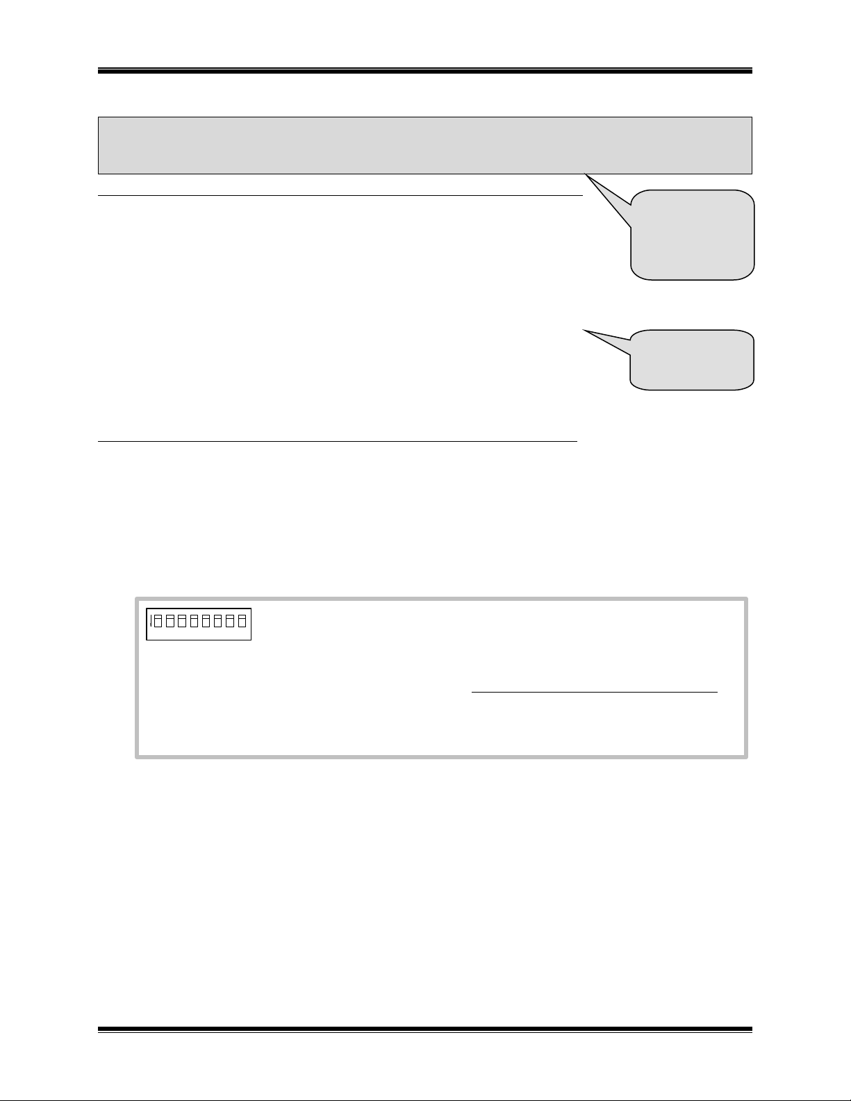
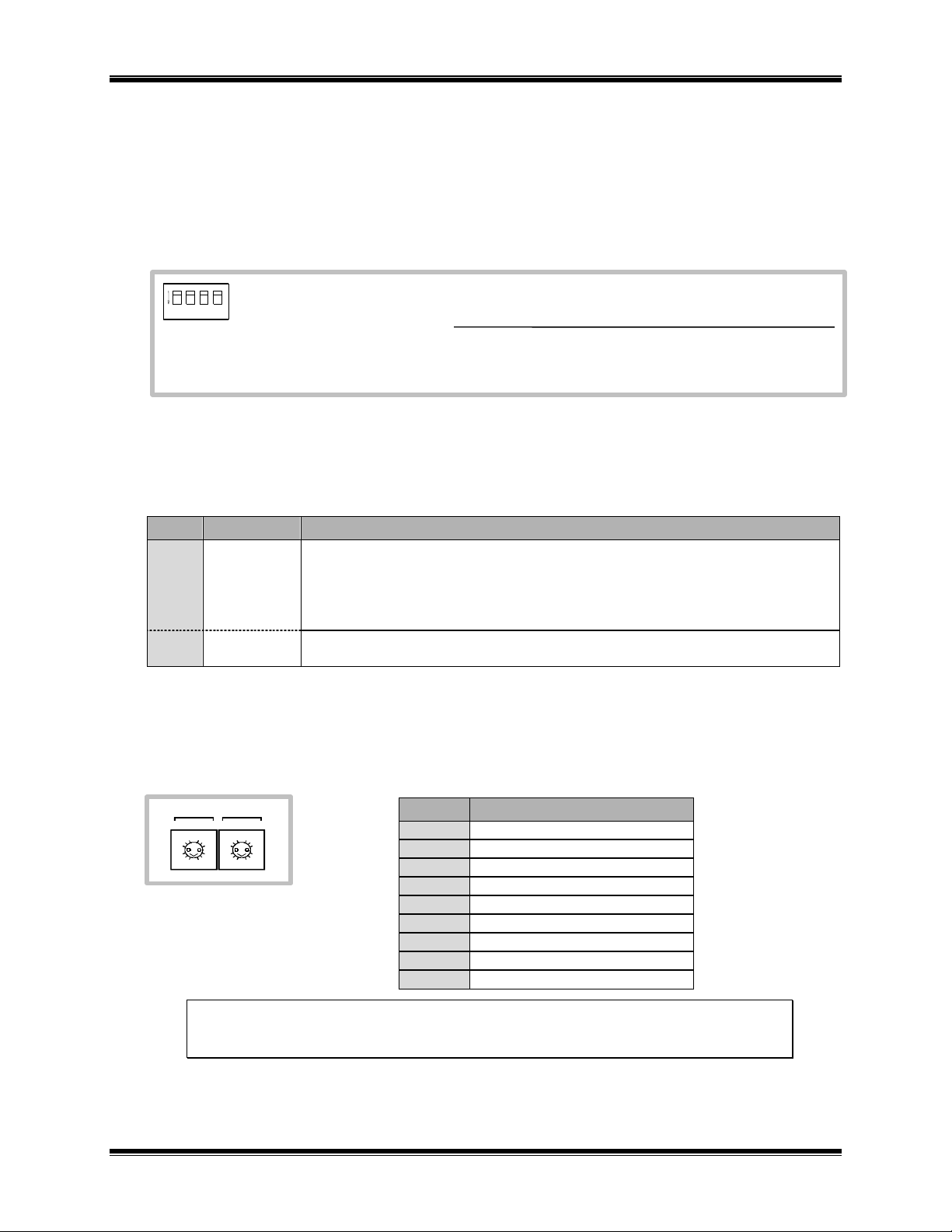
OPTION A Switches
OPTION A switches set the LonWorks addressing parameters (switches 5 and 6). Leave the unused switches
in the UP position. The position of the OPTION A switches are read by the NCB at module power-up or after
pressing the “RESET” button on the front panel.
Setting the LonWorks Addressing Parameters (Switches 5 and 6)
Switches 5 and 6 provide a simple (but very limited) method of setting the LonWorks domain/subnet/node
address of the internal Control Neuron Processor. This method is useful for systems with two NCB modules,
but does not provide enough flexibility for larger systems. (Standard Network Management Tools are a much
better choice.) For more information on setting this address, see “STEP 5. IMPLEMENTATION IN A NETWORK”
for a tutorial on network management tools.
If OPTION A Switch 5 is UP, Switch 6 determines a static subnet/node address for the Control Neuron
Processor: Switch 6 DOWN fixes the Control Neuron Processor subnet/node address at 255/1 in the
zero-length domain, while Switch 6 UP fixes the subnet/node address at 255/2 in the zero-length
2. Setup and Operation 9
domain. This setting allows for a quick evaluation of the NCB modules, requiring minimal user setup.
Page 16
CTI Products, Inc. NCB-EM User Guide
1. PORT 1 Auto Answer Mode .............Disabled Enabled (Normal)
2. PORT 1 DSR sense.........................Disabled Enabled (Normal – Leave UP for Leased-Line)
3. PORT 2 Auto Answer Mode .............Disabled Enabled (Normal)
4. PORT 2 DSR sense.........................Disabled Enabled (Normal – Leave UP for Leased-Line)
DOWN UP
123
4
ON
Signal
Direction
Function
DSR
Input to NCB
Active when a connected device is functioning.
This signal is driven by the connected device’s DTR signal.
If driven inactive, NCB front panel “ERR” LED will flash quickly, and NCB
will not communicate with this device.
If DSR signal is not available from connected device, strap to DTR output.
DTR
Output from
NCB
Always driven active by NCB.
Position
Function/Baud Rate
0
Disable Port
1
1200 Baud
2
2400
3
4800
4
9600
5
19200
6
38400
7
57600
8
115200
897
A
B
C
D
EF0
1
2
3
4
56897
A
B
C
D
EF0
1
2
3
4
5
6
BAUD 1
BAUD 2
If OPTION A Switch 5 is DOWN, dynamic determination of the domain/subnet/node number by a
Network Management Tool is allowed.
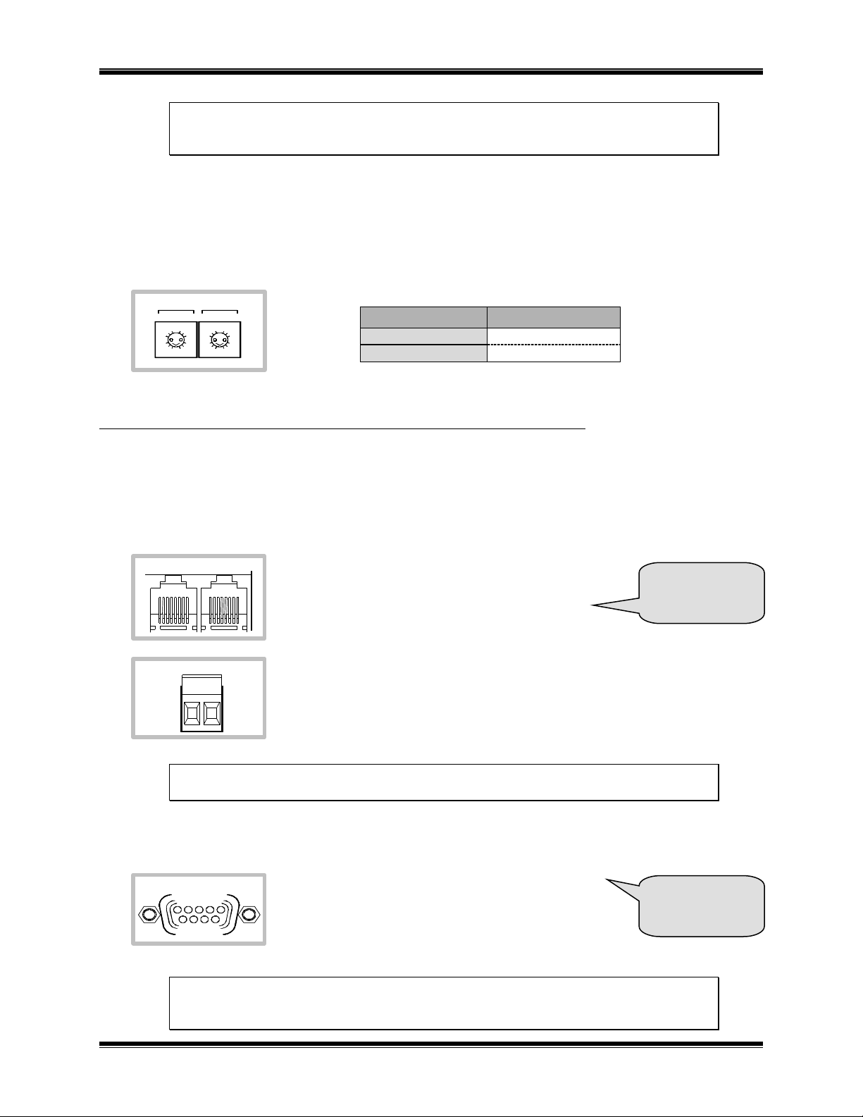
OPTION B Switches
OPTION B switches set the Automatic Answer feature of the dial-up type external modem and Serial Port
Handshaking options.
A dial-up type external modem can be commanded to dial out regardless of its’ Auto Answer Mode
Enable/Disable setting.
DSR/DTR handshaking informs the NCB that a connected device is active. If the channel does not directly
support DSR/DTR handshaking, DSR must be strapped back to the (always active) DTR output signal.
When enabled, the operation of DSR/DTR is as follows:
BAUD Switches
“BAUD 1” and “BAUD 2” switches correspond to “PORT 1” and “PORT 2” connectors and allow either
disabling the port for use or enabling it at a specific baud rate.
NOTE: Set the “BAUDn” switch to 0 if the respective port will not be used. This is
important, as the front panel “ERR” LED will flash continuously if a serial port “BAUD”
switch is non-zero and no modem is connected.
2. Setup and Operation 10
Page 17
CTI Products, Inc. NCB-EM User Guide
Modem Type
MODE Setting
Dial-Up
C
Leased-Line
D
897
A
B
C
D
EF0
1
2
3
4
56897
A
B
C
D
EF0
1
2
3
4
5
6
MODE 1
MODE 2
NETWORK
OUT
IN
NETWORK
See Appendix C
for pinouts and
cable diagrams.
PORT 1
123
4
678
9
5
See Appendix C
for Connector
Details
NOTE: When used with the current external dial-up modem (with “MODE” switch set to C),
the baud rate is fixed internally to 57600 bps and the “BAUD” switches have no effect other
than setting 0 will still disable the port for use.
Mode Switches
“MODE 1” and “MODE 2” switches allow setting the NCB for compatibility with certain types of external
modems (i.e. dial-up or leased-line). A different type of modem can be connected to each port. NOTE:
previous versions of the NCB unit have only one “MODE” switch. It this case, two modems can still be
connected to a single NCB unit, but they must both be of the same type (either both dial-up or both leased-line).
STEP 3. ELECTRICAL CONNECTIONS
LonWorks Network Connection
The local LONWORKS network must be attached to the NCB module via the “NETWORK” connector following
standard Echelon guidelines as to cable type, cable length, and termination appropriate for the selected
transceiver.
The dual RJ45 “NETWORK” connector allows a
daisy-chained network connection method, as the
network pins of the two RJ45 connector are directly
paralleled. Note that other pins on the RJ45 are
connected to circuit ground and DC power.
The 2 pin removable terminal strip is wired in parallel with the network connections
on the dual RJ45 connector.
NOTE: If your NCB module was purchased without a LonWorks transceiver (SMX-ready),
refer to Technical Note TN025 to install your SMX transceiver.
Modem Connection
Connect the external modem(s) to “PORT 1” (and
“PORT 2” if two modems are being used) on the rear
of the NCB unit using the cable(s) supplied with the
modem(s) (this is a standard 9 pin to 25 pin modem
cable). Attach the telephone line and provide power
to the external modem(s) per the modem manufacturer requirements.
NOTE: Set the BAUD 1, BAUD 2, MODE 1, MODE 2, and OPTION B switches
according to information in section “2. SETUP AND OPERATION”, “STEP 2. SWITCH SETUP”
BEFORE powering up the NCB module.
2. Setup and Operation 11
Page 18

CTI Products, Inc. NCB-EM User Guide
See “Appendix G.
Modem Notes”
for 4-Wire
Leased-Line
pinouts and wire
colors.
DC IN
Dial-Up Modems
A dial-up connection uses a 2-wire connection scheme to a standard telephone circuit. A standard telephone
cord can be used.
Leased-Line Modems
A leased-line connection can use either a 2-wire or 4-wire scheme to a dedicated leased-line circuit:
2-Wire Leased-Line
In 2-wire Leased-Line mode, the audio circuit must pass audio simultaneously in both directions. For this
mode, use pins 3 & 4 (red and green) of the “LEASE/PRIVATE” connector. Pins 2 and 5 are unused in 2-wire
mode.
For testing “on the bench” in 2-wire Leased-Line mode, two modems may be connected “back-to-back” using
the standard modular telephone cable provided with each modem. For this short cable back-to-back
connection, however, MODEM DIP Switch 3 must be placed in the UP position (followed by resetting the
NCB unit) on BOTH NCB units. This lowers the transmit level to prevent clipping of the signal due to the
short (near lossless) cable. Be sure to return MODEM DIP Switch 3 to the DOWN position before installing
the modem in the field. (Leased-Line modems designed for use in the United Kingdom will require a cable that
uses the outer 2 pins of a 6-pin RJ11 connector.)
4-Wire Leased-Line
In 4-wire Leased-Line mode, two pairs are used, one for Transmitting to the other
NCB and one for Receiving from the other NCB. For this mode, pins 3 & 4 (red
and green) of the “LEASE/PRIVATE” connector carries ‘transmit audio’ from
this unit to the other unit and pins 2 & 5 (black and yellow) carries ‘receive audio’
to this unit from the other unit. A 4-wire leased-line telephone circuit has two
channels and each channel carries audio in only one direction.
For testing “on the bench” in 4-wire Leased-Line mode, two NCB units with
modems must be connected “back-to-back” by connecting the transmit pair of each unit to the receive pair of
the opposite unit. This cannot be done with the telephone cable having modular connectors on both ends, as
this cable is wired “straight through”. Instead, use the modular plug to spade lug cables provided. Also, for this
short cable back-to-back connection, MODEM DIP Switch 3 must be placed in the UP position on BOTH
modems (followed by resetting the modems). This lowers the transmit level to prevent clipping of the signal
due to the short (near lossless) cable. Be sure to return MODEM DIP Switch 3 to the DOWN position before
installing the modem in the field.
DC Power Connection
DC power must be attached to the NCB module via the DC IN connector (see
“APPENDIX C. CONNECTOR DETAILS”). Apply DC power to the NCB module
only after all other connections have been made. A wall plug-in style power
supply designed for the NCB module is an available option.
2. Setup and Operation 12
Page 19

CTI Products, Inc. NCB-EM User Guide
STEP 4. MODEM CONFIGURATION
MultiTech Modem Model MT2834ZDX (Dial-Up)
Configuration of this external dial-up modem is performed automatically by the NCB module. No manual user
intervention is required.
MultiTech Modem Model MT2834L (Leased-Line)
This external leased-line/dial-up modem must be configured before use with the NCB module. Configuration
parameters are stored in the non-volatile memory of the modem and, therefore, only needs to be performed
when first installing (or replacing) the modem. Use the following steps to configure this modem model:
a) Set the DIP switches on the side of the modem as follows:
1: DOWN 5: # 9: DOWN 13: UP
2: UP 6: UP 10: UP 14: UP
3: * 7: DOWN 11: DOWN 15: UP
4: UP 8: DOWN 12: DOWN 16: UP for 2-Wire, or
DOWN for 4-Wire
* Set DOWN normally, UP to connect modems back-to-back with a short cable.
# For a single dedicated phone line, one modem must have switch 5 DOWN, the other modem
must have switch 5 UP.
b) Set NCB module switches as follows:
MODE 1: C BAUD 1: 7 BAUD 2: 0 OPTION B, 1 & 2: UP
c) Connect the modem to the NCB “PORT 1” connector.
d) Power up the NCB unit and the modem (any order).
e) Wait for the “ERR” LED on the front of the NCB unit to stop flashing. When it does, power down the
NCB unit and the modem.
f) Change DIP switch 10 on the modem to DOWN.
g) Reconnect the modem to the desired NCB “PORT 1” (if different from the NCB used for
configuration) and change “MODE 1” to the “D” position.
h) Re-power the NCB unit and modem.
2. Setup and Operation 13
Page 20

CTI Products, Inc. NCB-EM User Guide
Why is a Network Management Tool
needed?
Factory Default Settings
An NCB could be placed in a network using the
configuration as it was shipped from the factory
(Repeater Mode, fixed Subnet/Node address). All
messages would simply be passed through the NCB.
This may suffice for small networks where channel
bandwidth and message timing issues are of no
concern.
Use of a Network Management Tool
If a larger network is planned, and channel bandwidth
limitations require segmentation of message traffic,
then a Network Management Tool should be used to
perform some or all of the following functions:
Assign unique addresses to each NCB Router
and Control Neuron
Configure domain address tables in routers
Optimally set Transaction Timers based on
Channel Delays
Configure forwarding tables in routers for traffic
segmentation
Tutorial . . .
?
STEP 5. IMPLEMENTATION IN A NETWORK
Will a Network Management
Tool Be Used?
If NO, and the NCB will be used
with its factory default settings
(Repeater Mode), skip the rest of
this section. The NCB is ready to
function in a network.
If NO, and the DOS NCBCON
program will be used to access
and configure the Control Neuron
Processor, then see Technical
Note TN023.
If YES, and LonMaker For
Windows will be used, be certain
that ‘OPTION A Switch 5 is in
the DOWN position, and see
Commissioning the NCB with
LonMaker for Windows later in
this section.
If YES, and another Network
Management Tool will be used, be
certain that ‘OPTION A Switch 5
is in the DOWN position, then see
Technical Note TN026.
Commissioning the NCB with LonMaker for Windows
Commissioning each NCB in a network with LonMaker for Windows involves commissioning two different
network devices, both contained in the single NCB enclosure: a standard LonWorks router, and the control
neuron.
Since the standard LonWorks router portion of an NCB router interfaces a LonWorks channel to a Telephone
(WAN) channel, it requires connection to two channels on the LonMaker drawing. A standard LonWorks
channel will be connected to Side B of the router shape, and a CUSTOM (Telephone, WAN) Channel will be
connected to Side A of the router shape.
Commissioning the NCB control neuron requires that the .XIF file be available. The simplest way to do this is
to install the NCB/Plug plugin, as this process copies the required .XIF file to the proper directory.
2. Setup and Operation 14
Page 21

CTI Products, Inc. NCB-EM User Guide
Installing NCB/Plug Configuration Plug-in
A) Install the NCB/Plug plug-in on your PC:
Insert the NCB/Plug CD into your CD-ROM drive.
Click the Windows Start button, choose Run..., click Browse… , select the Setup application on the
NCB/Plug CD, and click Open .
Follow the instructions displayed by the Setup application.
Restart your computer when the Setup application is complete.
NOTE: Two External Interface Files (.XIF) are automatically transferred to the hard drive
when NCB/Plug plug-in is installed. NCBTLC30.XIF should be used for the Control Neuron
Processor of an NCB of Version 3. NCBTLC20.XIF should be used for the Control Neuron
Processor of an NCB of Version 2.
B) Register NCB/Plug with LonMaker for Windows:
Click the Windows Start button, choose Programs, then NCBPlug, and click on NCBPlug.
Click Register Plug-In .
Click Exit .
C) Register NCB/Plug with the desired LonMaker for Windows network:
Start LonMaker for Windows and open the desired network (be sure to checkmark the “Show all
Network Option Screens” box). When the “Plugin Registration” window within the Network
Wizard appears, highlight the “NCB_Plug” under “To Be Registered” and click Finish.
After installing and registering the NCB/Plug plugin, commission the “local NCB” (the one whose
“NETWORK” port is connected to the NSI attached to LonMaker for Windows) using the following steps:
Commisioning the NCB
A) Add a CUSTOM channel to the network drawing (this will be the WAN channel):
Drag the Channel shape to the drawing. The “Channel Definition” window will be displayed.
Specify an appropriate Channel Name.
In the “Transceiver Type” field, click the down arrow and select CUSTOM.
In the “Delay” section, choose “Specify”, and enter a value of 150ms.
Enter a Channel Description, if desired.
Click OK to continue.
B) Add the standard LonWorks router portion of the NCB to the network drawing:
Drag the Router shape to the drawing. The “New Router Wizard” window will be displayed.
Specify the desired router name.
Click NEXT to continue.
In the “Channel A” Name field, choose the custom channel created in Step a.
In the “Channel B” Name field, choose the standard LonWorks channel connected to the
“NETWORK” connector on the NCB.
Click NEXT to continue.
Specify a Location string and Description, if desired. “Ping Interval” can be set as desired,
however should be set to “never” for remote NCB routers which are not connected full-time (for
example, those connected via dial-up telephone lines).
Click NEXT to continue.
Specify desired advanced router properties. Router Type : Configured is recommended.
Click FINISH to complete the “New Router Wizard”.
C) Add the Control Neuron Processor to the network drawing:
Drag the Device shape to the drawing. The “New Device Wizard” window will be displayed.
Specify the desired Device Name.
Click NEXT to continue.
2. Setup and Operation 15
Page 22

CTI Products, Inc. NCB-EM User Guide
In the “External Interface Definition” section, choose ‘Existing Template’, click the down arrow
and choose the appropriate template as follows: NCBTLC30.XIF should be used for the Control
Neuron Processor of an NCB of Version 3, NCBTLC20.XIF should be used for the Control
Neuron Processor of an NCB of Version 2.
Click NEXT to continue.
In the “Channel: Name:” section, choose the custom channel connected to Side A of the router that
was created in Step a.
Click NEXT to continue
Specify a Location string and Description, if desired. “Ping Interval” can be set as desired,
however should be set to “never” for remote NCBs which are not connected full-time (for example,
those connected via dial-up telephone lines).
Click FINISH to complete the “New Device Wizard”.
D) Commission the LonWorks router:
Right-click on the router shape added in step b.
Click on the Commission function
Select the Online state.
Click FINISH to commission the router.
E) Commission the Control Neuron:
Right-click on the Control Neuron device shape added in step c.
Click on the Commission function
Select the Online state and Current Values in Database for Source of Configuration Property
Values.
Click FINISH to commission the Control Neuron.
Figure 5--LonMaker NCB Diagram
2. Setup and Operation 16
Page 23

CTI Products, Inc. NCB-EM User Guide
NCB/Plug
LNS plug-ins are applications that can be started
from within an LNS application (such as the
LonMaker tool) to perform a specialized task. The
NCB/Plug plug-In implements configuration and
query commands for the NCB. The NCB/Plug
plug-In and Network Variables can be used
simultaneously. The following functions are
available if the NCB/Plug plug-In is installed:
Send a dial string to a modem
Send a ‘Call Cancel’ command to a modem
Configure the NCB Directory
A window displays ‘Connect Status’
Select Dial Mode (Manual Dial or Perpetual
Connect)
Configure Ring Mode parameters
Request a soft reboot of NCB
Tutorial . . .
Network Variables
Network Variable Bindings allow a device to send
and receive messages to and from other devices
on the network. All configuration and status
commands sent to the NCB module are carried on
the LonTalk network in the form of Network
Variables bound to the Control Neuron Processor
inside the NCB module. The following functions
are available if Network Variable bindings are
made:
Send a dial string to a modem
Send a ‘Call Cancel’ command to a modem
Request ‘Connect Status’ from a modem
Request a ‘Connect String’ output from a
modem
Select Dial Mode (Manual Dial or Perpetual
Connect)
Configure Ring Mode parameters
Request a soft reboot of NCB
Request Product Name Output from NCB
Tutorial . . .
?
?
STEP 6. CONTROLLING THE WAN CONNECTION
At this point, the “local” NCB (the one connected to the LonMaker for Windows NSI) has been configured and
fully commissioned for use. This last step involves making a connection to the “remote” NCB via the
Telephone (WAN) channel.
If a leased-line connection has been made to the remote NCB (via the actual leased-line to be used, or via a
back-to-back test phone cable) and the remote NCB has been configured properly, the “CD” LED on both units
should be on and message packets will flow between them across the Telephone circuit. To commission the
remote NCB router and control neuron, repeat B through E of Commissioning the Router in Step 5 above.
If a dial-up circuit is being used between the local and remote NCB’s, then the local NCB must be commanded
to dial into the remote NCB in order to commission it. The simplest way to command this dialing to occur is to
use the NCB/Plug plugin. Alternatively, the Network Variable interface can be used. See the following
tutorial. Once the dial-up connection is established with the remote NCB, message packets will flow between
them. To commission the remote NCB router and control neuron, repeat B through E of Commissioning the
Router in Step 5 above.
Network Variables and the NCB/Plug Plug-In
Will bindings be made to any
Network Variables?
If NO, you may wish to use the NCB/Plug
Plug-In (See ‘Tutorial: NCB/Plug’ above).
If YES, see SECTION 3, NETWORK VARIABLE
(NV) CONTROL. You may also wish to use
the NCB/Plug plug-in (See ‘Tutorial:
NCB/Plug’ above).
2. Setup and Operation 17
Will NCB/Plug be used?
If NO, you may wish to make Network
Variable bindings (See ‘Tutorial:
Network Variables’ above).
If YES, see SECTION 4, NCB/PLUG. You may
also wish to make Network Variable bindings
(See ‘Tutorial: Network Variables’ above).
Page 24

CTI Products, Inc. NCB-EM User Guide
Setup and Operation 18
Page 25

CTI Products, Inc. NCB-EM User Guide
This Section
contains details
of Network
Variables and
Bindings
Phone Book
Object
Some Alarm
Device
nviReqDialStr
nvoDialStr
Modem
Controller
Object
nviDialStr
nviCallCancel
nvoConnectStat
nvoCallCancel
nvoReqDialStr
nviConnectStat
3. NETWORK VARIABLE (NV) CONTROL
TYPICAL NV BINDINGS
All commands sent to the NCB module are carried on the LonTalk network in
the form of Network Variables bound to the Control Neuron processor inside the
NCB module (connected to Side A of the internal router). This section details the
Functional Blocks (objects) and the network variables of each.
The Modem Controller Object is typically used in conjunction with the Directory Object and some other eventgenerating object which causes connection control information to be given to the Modem Controller Object.
This information initiates modem dialing so that, once a connection is established, transfer of data can be
accomplished via the modem.
Figure 6 is an example of typical network variable bindings.
Figure 6 Typical Network Variable Bindings
3. Network Variable Control 19
Page 26

CTI Products, Inc. NCB-EM User Guide
Phone Book
Object 1
Some Alarm
Device
nviReqDialStr1
nvoDialStr1
Modem
Controller
Object 1
nviDialStr1
nviCallCancel1
nvoConnectStat1
nvoCallCancel1
nvoReqDialStr1
nviConnectStat1
Phone Book
Object 2
Modem
Controller
Object 2
nvoCallCancel2
nvoReqDialStr2
nviConnectStat2
nviReqDialStr2
nvoDialStr2
nviDialStr2
nviCallCancel2
nvoConnectStat2
The example in Figure 7 uses multiple Directory Objects with multiple Modem Controller Objects.
Figure 7 Multiple Directory Objects with Multiple Modem Controller Objects
MODEM CONTROLLER OBJECT
The Modem Controller Object is used to control the functions of the NCB Module’s data modem. These
functions include configuration, connection control, and connection status. Two Modem Controller Objects are
available, depending on the NCB model being used. ‘Internal Modem’ is for use with the NCB-IM. ‘External
Modem1’ and ‘External Modem 2’ are for use with the NCB-EM and NCB-IS. All Modem Controller Objects
have identical network variable inputs and outputs.
3. Network Variable Control 20
Page 27

CTI Products, Inc. NCB-EM User Guide
Value
Call Cancel
Off
No Action
On
Modem goes On-Hook
Network Variables
Dial String (Input)
C Language Syntax
network input SNVT_str_asc nviDialStr1;
network input SNVT_str_asc nviDialStr2;
Usage
A non-null string sent to this input network variable while the current modem connection state
is TEL_NOTINUSE causes the modem to go off hook, wait for a dial tone, then perform a
dialing sequence using the provided character string.
A non-null string sent to this input network variable while the current modem connection state
is other than TEL_NOTINUSE has no effect on the modem connection state or action.
A null string sent to this input regardless of current modem connection state has no effect on
the modem connection state or action.
Valid Range
A NULL terminated ASCII string up to 31 bytes in length.
All ASCII characters are valid, with specific support for the following:
Letter P (upper or lower case, first character in string only) – Pulse Dial.
Digits (0-9,*,#) – Dials digit directly.
Comma (,) – Pauses 2 seconds for each comma encountered.
Letter W (upper or lower case) – Pauses until a dial tone is detected.
Exclamation Point (!) – Hookflash, go onhook for 0.5 seconds, then back offhook.
Punctuation (space, dash, left and right parentheses) – Valid in string, but ignored.
Call Cancel (Input)
C Language Syntax
network input SNVT_switch nviCallCancel1;
network input SNVT_switch nviCallCancel2;
Usage
An input value of ON to this network variable causes the modem to immediately go onhook,
terminating the connection attempt in progress or breaking the existing connection to the
distant modem. The modem returns to the TEL_NOTINUSE state.
Valid Range
3. Network Variable Control 21
Default Value
Off
Page 28

CTI Products, Inc. NCB-EM User Guide
Value
Output String
Description
0
TEL_NOTINUSE
Modem onhook and idle
1
TEL_OFFHOOK
Modem waiting for dialtone
2
TEL_DIALING
Modem dialing (and training for NCB/EM)
3
TEL_DIALCOMP
Modem executing mid dial pause (NCB/IM only)
7
TEL_ANSWERED
Modem training (NCB/IM only)
9
TEL_TALKING
Modem connected and online with distant modem,
ready to send data
12
TEL_HOLD
Modem retraining (NCB/IM only)
20
TEL_ERROR
Modem initializing, not present, or port diabled
Connect Status (Output)
C Language Syntax
network output SNVT_telcom nvoCnctStat1;
network output SNVT_telcom nvoCnctStat2;
Usage
This output network variable provides the current state of the modem connection process.
Valid Range
When Transmitted
The output is updated upon each change in modem connection state.
Update Rate
The output is updated only once per change in modem connection state.
Connect String (Output)
C Language Syntax
network output SNVT_str_asc nvoCnctStr1;
network output SNVT_str_asc nvoCnctStr2;
Usage
This output network variable provides detail in text format of the connection parameters
established after the modem connection has reached the TEL_TALKING state. These
parameters include connect speed, protocol, error correction, etc.
Valid Range
A NULL terminated ASCII string up to 31 bytes in length.
When Transmitted
The output is updated when the modem connection state reaches TEL_TALKING or
TEL_NOTINUSE.
Update Rate
This network variable is updated once after the modem has entered the TEL_TALKING state and
once after the modem has entered the TEL_NOTINUSE state.
3. Network Variable Control 22
Page 29

CTI Products, Inc. NCB-EM User Guide
Request Dial String (Output)
C Language Syntax
network output SNVT_char_ascii nvoReqDialStr1;
network output SNVT_char_ascii nvoReqDialStr2;
Usage
This output network variable is associated with Perpetual Dial-Up Mode (see Tutorial
“Which Modem Mode Should Be Used” in section “2. SETUP AND OPERATION”) and is used
when the Directory Object storing the telephone number (to be dialed) belongs to a node
other than the call-originating NCB.
Valid Range
0-F (Hex)
When Transmitted
Transmitted when the Modem Controller Objectsenses that a connection is not made.
Perpetual Dial-up Mode
The NCB module can be configured to provide a “perpetual” connection using the ‘dial-up’ mode
of the modem, with no runtime user or application intervention required to initiate or maintain a
constant modem connection. See “APPENDIX G. MODEM NOTES” for more details of Perpetual
Dial-up Mode.
There are two methods available for implementing a “perpetual” connection using Dial-up mode:
1) The first method uses only configuration properties. This method is useful when the Directory
Object storing the telephone number (to be dialed) belongs to the dialing NCB module.
a) Specify an entry in an NCB’s Directory that contains the phone number to be dialed.
This can be accomplished using either the NCB/Plug plug-in (discussed in “Section 4.
NCB/Plug” or using the “Dial Mode” Configuration Property (discussed later in this
section).
b) Set the “Dial Mode” (for the call-originating NCB) to “Perpetual”. This can be
accomplished most easily with the NCB/Plug plug-in (discussed in “Section “4.
NCB/Plug” by accessing Dial Mode choices under the Modem Options menu item.
Changing the Dial Mode to Perpetual may also be accomplished by using the “Dial
Mode” Configuration Property (discussed later in this section).
2) The second method uses a combination of configuration properties and network variable
bindings. This method is useful when the Directory Object storing the telephone number (to
be dialed) belongs to a node other than the call-originating NCB.
a) Specify an entry in an NCB’s Directory that contains the phone number to be dialed.
This can be accomplished using either the NCB/Plug plug-in (discussed in “Section 4.
NCB/Plug” or using the “Dial Mode” Configuration Property (discussed later in this
section). This step is the same as in the first method.
b) Set the “Dial Mode” to “Manual” mode (the default setting).
c) Make network variable bindings as shown in Figure 8.
3. Network Variable Control 23
Page 30

CTI Products, Inc. NCB-EM User Guide
Phone Book
Object
nviReqDialStr
nvoDialStr
Modem
Controller
Object
nviDialStr
nvoReqDialStr
Figure 8 Perpetual Dial-up Mode using NV Bindings
3. Network Variable Control 24
Page 31

CTI Products, Inc. NCB-EM User Guide
Why are Configuration Properties
important?
Configuration Properties of an object (such as the
Directory Object or Modem Controller Object) are
used to alter the operation of a device. These
properties are normally setup parameters that are
accessed just once for purposes of initialization.
However, they may be altered at any subsequent
time.
Configuration Properties may need to be changed
from default values if any of the following is required:
Perpetual Connect mode enabled (in Modem
Controller Object).
Auto Answer mode disabled (in Modem
Controller Object).
Dial string entry (in Directory Object),
Ring Mode enabled and parameters initialized
(in Global Control Object).
Accessing Configuration Properties
Alternative methods of accessing Configuration
Properties are available:
Direct access by either Network Variable
bindings or File Transfer (if a large amount of
data is involved).
Indirect access when a plug-in is used, such as
the NCB/Plug plug-in.
Tutorial . . .
?
Configuration Properties
Will Configuration Properties
be modified? ff
If NO, and the NCB objects
(functional blocks) will be used
with factory default settings
(Manual Dial-Up or Leased-Line
modes, Auto Answer mode
Enabled, Ring Mode disabled),
skip to Directory Object, later in
this section.
If YES, but the NCB/Plug plug-in
will be used to modify the
Configuration Properties, skip to
Directory Object, later in this
sections and also section “4.
NCB/PLUG”.
If YES, then the information
following is this section will be
useful.
3. Network Variable Control 25
Page 32

CTI Products, Inc. NCB-EM User Guide
Mode:
Value
Dial-up Mode
Index: 0-F hex
0 Manual
1
Perpetual
Dial Mode
C Language Syntax
Typedef struct UCPT_DialMode
{
unsigned char Mode;
unsigned char Index;
}
network input config SCPTdialMode UCPT_DialMode1;
network input config SCPTdialMode UCPT_DialMode2;
Usage
This input configuration network variable allows the modem dialing Mode (Manual or
Perpetual) to be set, as well as the Directory entry Index number (0 through 15) that should be
used when dialing in Perpetual mode. These configuration properties can also be modified
using the NCB/Plug plug-in as described in section “4. NCB/PLUG” and “APPENDIX G.
MODEM NOTES”
Manual dial mode requires either of the following for dialing to take place:
A string should be sent to nviDialStr input network variable of the Modem
Controller Object.
Or, a character representing the entry Index number should be sent to nviReqDialStr
input network variable of the Directory Object. In addition, a binding is need
between nvoDialStr of the Directory Object and nviDialStr of the Modem Controller
Object.
Perpetual mode causes the modem to automatically dial a number stored in the specified
Index entry of the local Directory Object amd requires the following:
The Dial Mode configuration property should be used to set the Mode to Manual,
and the Index to a Directory entry that will be used when dialing. In addition, the
Directory’s configuration property Dial String should be used to add the dial string
to the proper Index of the Directory. (See Directory Configuration Properties later
in this section.)
If the modem is currently connected to another NCB, the Dial Mode will not change until
the current call is cancelled.
Valid Range
Default Value
Mode: 0 Index: 0
Auto Answer Enable/Disable
C Language Syntax
network input config snvt_switch UCPT_AutoAnswer1;
network input config snvt_switch UCPT_AutoAnswer2;
Usage
This input configuration network variable provides a mechanism to enable or disable the
‘Auto Answer’ modem function.
3. Network Variable Control 26
Valid Range
Page 33

CTI Products, Inc. NCB-EM User Guide
Value
Auto Answer Mode
Off
Disabled
On
Enabled
Default State
On (Enabled)
TELEPHONE DIRECTORY OBJECT
A Directory Object is used to store and retrieve arrays of ASCII strings that are characterized as telephone
numbers (including characters used for control) used in dialing a data modem. The ASCII arrays are configured
using data file transfer or configuration network variables and are retrieved in real-time using an index value
passed via a network variable.
The output of a Directory Object (which emits telephone numbers) is typically bound to a Modem Controller
Object. . The input to a Directory Object is typically driven by an object requiring the services of the Modem
Controller Object to accomplish some connectivity task, e.g. notification of an alarm to a remote site. Usage of
a Directory Object allows the alerting object to initiate dialing of the Modem Controller Object to a specific
telephone number by simply emitting an array index from 0 to 15.
Two Directory Objects are available, for independently sending a distinct dial string to each of two Modem
Controller Objects. The Directory Objects use the same configuration data (all contain the same dial string
data).
Network Variables
Request Dial String (Input)
C Language Syntax
network input SNVT_char_ascii nviReqDialStr1;
network input SNVT_char_ascii nviReqDialStr2;
Usage
Two variables are available, one for each of the Directory Objects. These input network variables
request the output of a telephone number, from the requested index.
Valid Range
0-15
Dial String (Output)
C Language Syntax
network output SNVT_str_asc nvoDialStr1;
network output SNVT_str_asc nvoDialStr2;
Usage
Two variables are available, one for each of the Directory Objects. These output network
variables provide the phone number string from the Directory entry corresponding to the index
number received on nviReqDialStrx.
Valid Range
A NULL terminated ASCII string up to 31 bytes in length (including the NULL).
All ASCII characters are valid, with specific support for the following:
Letter P (upper or lower case, first character in string only) – Pulse Dial.
Digits (0-9,*,#) – Dials digit directly.
Comma (,) – Pauses 2 seconds for each comma encountered.
Letter W (upper or lower case) – Pauses until a dial tone is detected.
Exclamation Point (!) – Hookflash, go onhook for 0.5 seconds, then back offhook.
3. Network Variable Control 27
Page 34

CTI Products, Inc. NCB-EM User Guide
Punctuation (space, dash, left and right parentheses) – Valid in string, but ignored.
When Transmitted
Transmitted upon receipt of a valid nviReqDialStr input, unless requested entry index is not
supported or entry is blank (first character of entry is a NULL), in which case this variable is not
transmitted.
Receipt of another nviReqDialStr input causes this output to be transmitted, containing the phone
number string from the Directory entry corresponding to the index received on nviReqDialStr,
even if the index received is the same index as received on the previous update to nviReqDialStr.
Update Rate
Updated only on an update to nviReqDialStr input.
Configuration Properties
Dial String
C Language Syntax
network input config SNVT_str_asc nciSetPhoneNum;
Usage
The first byte (character) specifies the Index entry (0-F hex) of the Directory Object. Up to 29
additional bytes (characters) can be used to specify the dial string.
Valid Range
A NULL terminated ASCII string up to 31 bytes in length (including the NULL).
All ASCII characters are valid, with specific support for the following:
Letter P (upper or lower case, first character in string only) – Pulse Dial.
Digits (0-9,*,#) – Dials digit directly.
Comma (,) – Pauses 2 seconds for each comma encountered.
Letter W (upper or lower case) – Pauses until a dial tone is detected.
Exclamation Point (!) – Hookflash, go onhook for 0.5 seconds, then back offhook.
Punctuation (space, dash, left and right parentheses) – Valid in string, but ignored.
Default Value
The NULL character.
The File Transfer method of communications can also be used to configure the Dial String(s)
in a Directory Object. A Dial String Array (nciDialStr[16]) can be loaded with the desired
dial strings. This array holds data of type SNVT_str_asc.
GLOBAL CONTROL OBJECT
The following network variables pertain to the entire NCB, and not just to a single Modem Controller object or
Directory Object.
Product Name (Output)
C Language Syntax
network output SNVT_str_asc nvoProductName;
Usage
This output network variable contains an ascii string identifying the product.
When Transmitted
Unsolicited at power-up and reset, or when polled.
3. Network Variable Control 28
Page 35

CTI Products, Inc. NCB-EM User Guide
Value
Ring Status
Off
Open
On
Closed
Ring Status (Output)
C Language Syntax
network output SNVT_switch nvoRingStat;
Usage
This output network variable provides ring open or closed status. It has no function in the NCBIM.
Valid Range
Configuration Properties
Ring Mode Parameters
Typedef struct UCPT_RingMode
{
unsigned char Enable;
unsigned char UnitNumber;
unsigned long PropDelay;
unsigned long TestInterval;
}
Usage
This output structure contains setup information when a group of NCB Modules are configured in
a redundant ring topology. It has no function in the NCB-IM. See “APPENDIX H. RING MODE ”
for additional Ring Mode details.
Valid Range
Enable: 0 (Disabled), 1 (Enabled)
UnitNumber: 0 to 64
PropDelay: 1,000 to 7,500 (ms)
TestInterval: 10,000 to 65,000 (ms)
When Transmitted
When polled.
3. Network Variable Control 29
Page 36

CTI Products, Inc. NCB-EM User Guide
4. NCB/PLUG CONFIGURATION PLUG-IN
LNS plug-ins are applications that can be started from within an LNS application (such as LONMAKER for
Windows) to perform a specialized task. The NCB/Plug plug-in implements configuration and query
commands for the NCB. The NCB/Plug plug-in and Network Variables can be used simultaneously. The
following functions are available if NCB/Plug is installed:
Pulse router service pin
Request a soft reboot of NCB
The following function (for models NCB-EM, NCB-IS, and NCB-AY) will also be displayed, but will have no
effect when using NCB-IM and NCB-RF models:
Configure Ring Mode parameters
The following functions (for models NCB-IM, NCB-EM, and NCB-IS) will also be displayed, but will have no
effect when using NCB-AY, and NCB-RF models:
Send a dial string to a modem
Send a ‘Call Cancel’ command to a modem
Configure the NCB Directory
A window displays ‘Connect Status’
Select Dial Mode (Manual or Perpetual)
Select Auto Answer Enabled Mode
INSTALLATION
NOTE: If you have already performed these steps as detailed in Section 2 “Setup and Operation”, they do NOT
need to be repeated here. In this case, skip directly to “Accessing NCB/Plug” below.
1. Install the NCB/Plug plug-in on your PC:
a) Insert the NCB/Plug CD into your CD-ROM drive.
b) Click the Windows Start button, choose Run..., click Browse… , select the Setup application on
the NCB/Plug CD, and click Open .
c) Follow the instructions displayed by the Setup application.
d) Restart your computer when the Setup application is complete.
2. Register NCB/Plug with LonMaker for Windows:
a) Click the Windows Start button, choose Programs, then NCBPlug, and click on NCBPlug.
b) Click Register Plug-In .
c) Click Exit .
3. Register NCB/Plug with the desired LonMaker for Windows network:
a) Start LonMaker for Windows and open the desired network (be sure to checkmark the “Show all
Network Option Screens” box). When the “Plugin Registration” window within the Network
Wizard appears, highlight the “NCB_Plug” under “To Be Registered” and click Finish.
Two External Interface Files (.XIF) are automatically transferred to the hard drive when NCB/Plug plug-in is
installed. NCBTLC30.XIF should be used for the Control Neuron Processor of an NCB of Version 3.
NCBTLC20.XIF should be used for the Control Neuron Processor of an NCB of Version 2.
4. NCB Plug-In 30
Page 37

CTI Products, Inc. NCB-EM User Guide
ACCESSING NCB/PLUG
a) Bring NCB/Plug to the desktop:
b) Right click on the Control Neuron Functional
Block to be configured (Modem, Directory,
Globals). In the drop-down list, click
“Configure”. The Plugin will appear as
shown here.
c) Alternatively, right click on the Control
Neuron Processor device shape. In the dropdown list, click “Plug-Ins…”, and select
NCB/Plug. Click OK to continue. The Plugin will appear as shown here.
USAGE
Starting NCB/Plug from a Modem or Global Functional block shows the main NCB/Plug window from which
both modem and Directory configurations and operations may be performed. Starting NCB/Plug from a
Directory functional block shows only the Directory window from which only Directory information may be
configured or printed.
If LonMaker is currently in “Offnet” mode, only the configuration functions of NCB/Plug (including Directory
and certain Modem and NCB Options) will be available, and “<OFFNET>” will appear in the Message Box.
If the Control Neuron device being configured is not currently attached to the network, NCB/Plug will display a
“Connection Error”.
“Yes” may be clicked to retry communication with the device after reconnecting it.
“No” may be clicked to ignore the error and enter NCB/Plug to perform configuration functions only.
In this case, “No response from <device name>” will be shown in the Message box.
“Cancel” may be clicked to abort the load of NCB/Plug.
Manual Dialing
A dial string can be entered directly into the Phone Number box of the main NCB/Plug window. The Dial
button can then be used to initiate a call. The Call Cancel button can be used to terminate a call. Connect
Strings are displayed in the Message window. Connect Status is also displayed.
Directory Menu Item
The Phonebook menu item accesses the Directory and
is used to edit a list of 16 phone numbers (dial
strings). A Description field is available for each of
the 16 Number entries. Any entry in the Directory can
be accessed for dialing by using the pulldown button
of the Phone Number box on the main NCB/Plug
window. File -> Print to File pastes the current
Directory information to Windows Notepad from where it may be saved, printed, pasted, etc.
NCB Options Menu Item
The NCB Options menu item provides access to the following functions:
Pulse Router Service Pin
This is equivalent to pressing the “RSVC” button on the NCB’s front panel.
4. NCB Plug-In 31
Page 38

CTI Products, Inc. NCB-EM User Guide
Soft Reboot
This is equivalent to pressing the “RESET” button on the NCB’s front panel.
Ring Mode Parameters
NCB’s connected in a Ring topology provide fault tolerance for the Telco
channel. If values for Unit ID, Ring Propagation Delay, and Ping Test
Interval are edited, click on Apply Settings to save Ring Mode
Parameters. Click on the Enable/Disable menu item to display a drop-down
list, then choose Enable to activate ring mode for this NCB. See “APPENDIX
H. RING MODE ” for further Ring Mode details.
Modem Options Menu Item
The Modem Options menu item provides access to the following functions for an NCB-IM. These functions will
have no effect for other models (such as the NCB-EM).
Auto Answer (Dial-Up only)
This option allows enabling or disabling the Auto Answer function in Dial-up mode. A check next to the menu
item indicates Auto Answer is currently enabled. Be careful when disabling Auto Answer mode on a remote
NCB, as once connection with this unit is broken, it will no longer automatically answer an incoming call. To
re-enable Auto Answer mode, proceed as follows:
Press and hold the “CMD” button on the remote NCB
Press and release the “RESET” button on the remote NCB.
Wait until the “PWR” LED begins to flash on the remote NCB, then release the “CMD” button.
These steps will temporarily enable Auto Answer mode for the remote NCB for one incoming call. Use
NCB/Plug, NCBCON, or explicit messages to re-enable Auto Answer mode for future connections.
Mute Input Audio
To maximize data throughput, handsets should normally remain disconnected or the input audio be kept muted
on any NCB that may be installed where normal background noise could be detected by the handset. Audio
input is automatically un-muted when a connection is established
Dial Mode (Dial-Up only)
Manual or Perpetual dialing modes are supported. If the modem is currently
connected to another NCB, the Dial Mode will not change until the current
call is cancelled.
Connection Statistics
The Connection Statistics window appears to the right.
4. NCB Plug-In 32
Page 39

CTI Products, Inc. NCB-EM User Guide
4. NCB Plug-In 33
Page 40

CTI Products, Inc. NCB-EM User Guide
APPENDIX
APPENDIX A. FACTORY DEFAULT CONFIGURATION
Control Neuron Processor
Restoring Factory Default Parameters
Should the Control Neuron Processor communication parameters be overwritten incorrectly by a network
management tool, they can be restored as follows:
Press the “RESET” button on the front of the NCB unit
After the “ERR” LED goes off, press the “RESET” button a second time.
The Control Neuron communication parameters are now restored to factory defaults.
Router
The router portion of the NCB module may be configured for various operational characteristics. The factory
default configuration is as a repeater, where all messages entering the NCB module (via any of the three data
ports described in section “1. INTRODUCTION” are simply passed through, regardless of the domain,
subnet/node, or group destination address of the message. Other algorithms, as described in section “1.
INTRODUCTION”, can be selected using standard LONWORKS Network Management Tools such as the
LonBuilder, LonMaker, or LNS.
The communication parameters for sides A and B of the router are forced to their proper settings via NCB
hardware and need not be set (nor can they be changed) by the Network Management Tool.
Further details of router operation and configuration are contained in the Echelon document entitled "LonWorks
Router User's Guide", Echelon part number 078-0018-01B.
Address Assignments
The router inside the NCB module contains two Neuron chips, each with its’ own subnet/node number
assignment. The default factory configuration of the router Neurons is subnet 255 node 126 and subnet 255
node 127. If any other nodes in the system to which the NCB is connected are configured with either of these
subnet/node addresses, the router should be reconfigured to different addresses using any standard Network
Management Tool.
Buffer Configuration
The NCB module utilizes buffers to store incoming messages and route them out to other ports. The
configuration of these buffers (the number of bytes in each buffer as well as the number of buffers) determine
the maximum size message that can be passed and the performance of the NCB module under conditions of
bursty traffic. In the standard configuration, the NCB router restricts the maximum size message that can be
passed to a length of 40 to 50 bytes of user data, depending on the addressing overhead in the packet.
Technical Note TN010 covers the topic of buffers and buffer sizes in detail and should be referenced if
messages to be passed through the NCB module could exceed the maximum default size.
Appendix A. Factory Default Configuration 34
Page 41

CTI Products, Inc. NCB-EM User Guide
Querying, Defaulting, and Unconfiguring Router Configuration using SETRTR.EXE
The SETRTR.EXE DOS utility provided with each NCB can be used to query the router for its current
configuration, force the router to certain default states, or force the router to unconfigured mode. If the router
will be installed with the configured router algorithm, it is highly recommended that the router module is set to
unconfigured mode before being installed into the system (this step is mandatory if redundant routers are to be
configured).
Refer to Technical Note TN025 for more information on configuration of the router with standard network
management tools such as LonBuilder, LonMaker, LNS, and others.
The SETRTR program requires a network interface to be connected to the personal computer. This network
interface can be an Echelon SLTA, PCLTA, PCNSS, or any other device conforming to Echelon network
interface standards. Network interface driver software must be loaded in the personal computer and configured
with a device name (typically "LONn" where n is a number). Documentation provided with the network
interface device details how to install the unit and driver software. The network interface device must contain a
network transceiver compatible with the network transceiver in the NCB module to be controlled.
NOTE: If you are using the PCLTA card as a network interface and the NCB is not
performing the commands as expected, the PCNSS has probably not been configured for
network interface mode. See Technical Note TN024 for information on configuring the
PCNSS card into network interface mode.
After the network interface and its software driver are properly configured on the personal computer, connect
its’ network port to the front panel “NETWORK” connector on the NCB.
Querying an NCB Router for its Current Configuration
Start the SETRTR program with the following command line:
SETRTR [-ddevicename] -L <cr>
where devicename is the name assigned to the network interface on the command line of the device driver
(typically "LON1" or "LON2"). If this parameter is omitted, the default name of LON1 is used.
The -L parameter instructs SETRTR to List the current configuration of the router module.
After the signon message appears, press the “RSVC” button on the front of the connected NCB module.
SETRTR will report the current router configuration to the screen.
Returning an NCB Router to Factory Default Configuration
Start the SETRTR program with the following command line:
SETRTR [-ddevicename] -F <cr>
where devicename is the name assigned to the network interface on the command line of the device driver
(typically "LON1" or "LON2"). If this parameter is omitted, the default name of LON1 is used.
The -F parameter instructs SETRTR to set the RTR-10 to full Factory defaults, including router algorithm,
domain tables, and buffer settings.
After the signon message appears, press the “RSVC” button on the front of the connected NCB module.
SETRTR will send the required messages to the router and exit. Press the “RESET” button on the front of the
NCB module to complete the reconfiguration.
Setting an NCB Router to Unconfigured Mode
Start the SETRTR program with the following command line:
SETRTR [-ddevicename] -U <cr>
The -U parameter instructs SETRTR to set both sides of the NCB’s router to Unconfigured mode.
After the signon message appears, press the “RSVC” button on the front of the connected NCB module.
SETRTR will send the required messages to the router and exit.
Appendix A. Factory Default Configuration 35
Page 42

CTI Products, Inc. NCB-EM User Guide
CA-80113-100
1 2 3 4 5 6 7 8
ON
OPTION A
DC IN
ERR
ACT
PWR
RSVCCSVC
AUDIO
LINECD OH
RESET
CMD
NCB
NETWORK COMBINER
NETWOR K
FACEPLATE
SPACER
APPENDIX B. MOUNTING OPTIONS
Wall mount and EIA 19” rack mount kits are available as options for the NCB from CTI Products, Inc. The
wall mount kit includes brackets to allow a single NCB module to be mounted to any flat surface. The rack
mount kit includes an adaptor allowing up to three NCB modules to be mounted in a single rack unit height.
Rack Mount Option
The rack mount option allows up to three NCB modules to be mounted in a one rack unit height (1.75 inches) of
a standard 19 inch rack. The modules are mounted in the rack plate by removing its’ front bezel and
remounting the module into the rack plate. Figure 9 shows an exploded view of the rack mount installation.
The top diagram shows the front view of the bracket with one module installed. The bottom two diagrams show
a side view of the module installation into the rack adaptor and rack adaptor installation into the rack,
respectively.
Figure 9 NCB Module Rack Mounting
Appendix B. Mounting Options 36
Page 43

CTI Products, Inc. NCB-EM User Guide
Step
Operation
1
Remove the front panel from the module, including the bezel, by removing the two
Philips head screws in the faceplate. The bezel is not used when rack mounting the
module.
2
Position the module behind the rack adaptor, lining up the holes in the rack adaptor
with the front panel screw holes on the module.
3
Position the front panel in front of the rack adaptor, lining up the front panel with the
module.
4
Fasten the front panel and module to the rack adaptor with the Philips head screws that
were previously removed.
5
Position the rack adaptor into your rack, lining up the four mounting holes of the rack
adaptor with mounting holes in the rack frame.
6
Position the two spacers in the front of the rack adaptor, aligning the cutouts in the
spacers with the holes of the adaptor.
7
Install mounting screws (customer provided) into the rack.
Step
Operation
1
From the front of the module, slide the PC board out of the housing.
2
Remove the back panel of the module.
3
From the rear of the module, slide the PC board back into the housing (there are
markings on the PC board to indicate which edge to insert into the rear of the housing
first).
4
Install the back panel of the module.
To attach a module to the rack adaptor, and then mount the rack adaptor into the rack, follow the steps below.
WARNING
Do not allow the PC board to slide out of the housing when the front panel is removed. If it does,
DO NOT slide the PC board back into the housing from the front of the module. Doing so may
damage the unit, causing the unit to malfunction when powered on. Doing so will void the unit’s
warranty.
Rack Mounting Instructions
When the module’s front panel is removed, do not allow the PC board to slide out of the housing. If the PC
board does slide out of the housing, you must follow the steps below to replace the PC board in the housing.
DO NOT RE-INSTALL THE PC BOARD FROM THE FRONT OF THE HOUSING !
Re-Installing a PC Board in its housing
Appendix B. Mounting Options 37
Page 44

CTI Products, Inc. NCB-EM User Guide
Industry
Canada
NOTE:
THE NUMBE RS ON THIS DRAWING REFER TO THE ITEM NUMBERS
ON THE CORRES PONDING B ILLS OF MATERIAL FOR THIS ASSE MBLY.
24 VDC
100 m A
BOTTOM VIEW
US E O N LY 6- 3 2 X 1 / 4" LO N G
FL A T H EA D S CR E W S TO AT T AC H T HE
W A LL M O UN T B R AC KE T T O T HI S UN I T.
TO P R EV E N T D A M A G E TO T H E C I R CU I T BO A R D.
C A U T IO N !
US E O N LY 6- 3 2 X 1 / 4" LO N G
FL AT HE A D S CR EW S T O A TT A CH T H E
W A L L M O UN T BR A CK ET T O T H I S U NI T .
TO P R EV E N T D A M A G E TO T H E C I R CU I T BO A R D.
CAUTI O N!
Products Inc.
ETL APPRO
3.500
1.980
6.130
6.700
1.642
TOP VIEW
1
2
Provided by installer.
Allow ro om on ends
for connector s.
Allow ro om on ends
for connector s.
SIDE VIEW
1.980
QTY 2
QTY 4
QTY 4 NO . 8 SCR EW S OR OTHE R
AP PR OP RIATE HA RDW A RE.
OR
OR
DRAWN BY
APPROVED BY
SCALE
DATE
DATE
SHEET OF
TITLE
DRAWING NUMBER
1 1
NONE
APPLICATION
CFA
11-22-96
11-22-96
WON PRODUCTS
RKK
WON NC B S IZE "B " WA LL MOUNT K IT
1
2
3
4
5
6
7
8
ON
OPTIO N A
DC I N
ERR
ACT
PWR
RSVC
CSVC
AUDIO
LINE
CD
OH
RESET
CMD
NCB
NETWORK COM BINER
NETWORK
Wall Mount Option
The wall mount option allows an NCB module to be mounted to any flat surface. The NCB module has four
screw holes on the bottom. Simply attach the two mounting plates to the bottom of the module using the four
flat-head screws provided with the wall mount kit. This assembly is then attached to the flat surface with userprovided fasteners. Figure 10 shows a dimensioned view of the wall mount installation.
Be sure to use the flat head screws provided with the wall mount kit. If you are not using the wall mount
kit from CTI Products, Inc., make sure that the screws do not protrude into the enclosure more than 0.125
inches from the bottom surface of the module.
Using a longer screw that touches the PC board inside the module may damage the module. Doing so will
void the unit’s warranty.
Appendix B. Mounting Options 38
Figure 10 NCB Module Wall Mounting
CAUTION
Page 45
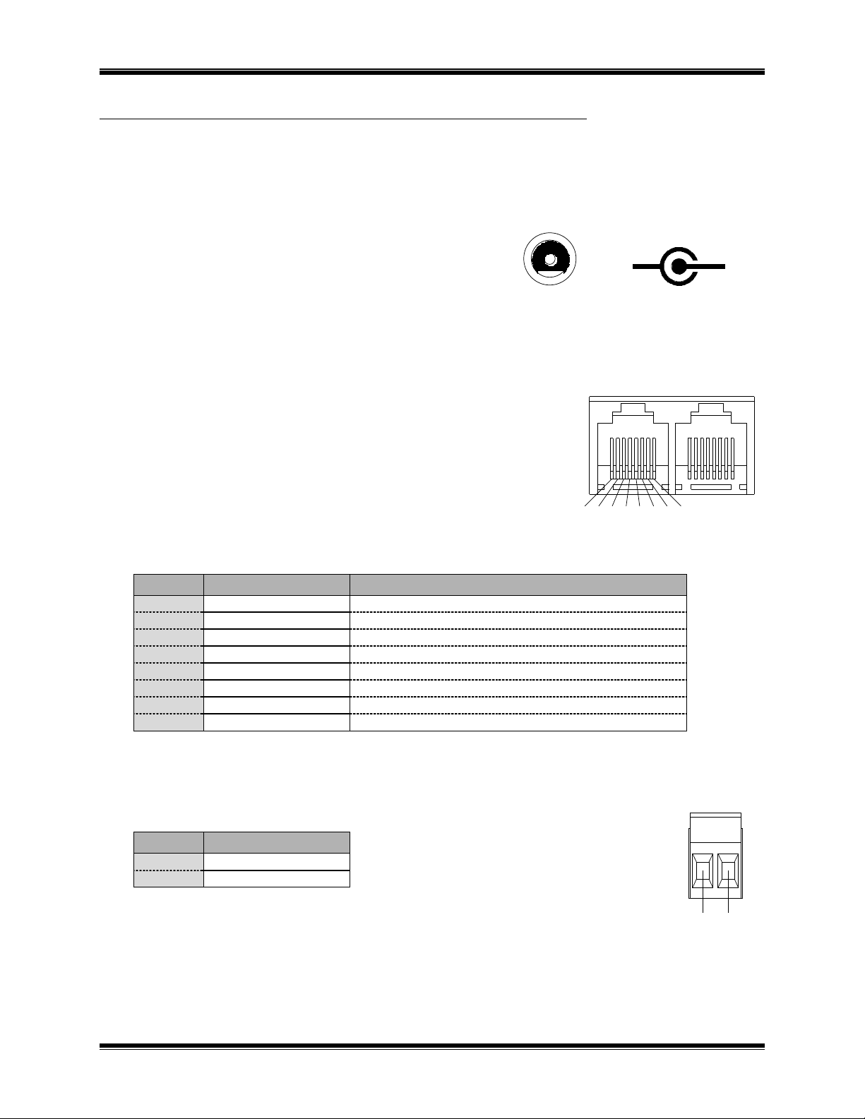
CTI Products, Inc. NCB-EM User Guide
Pin
Function
Notes
1
Network
Network connection is NOT polarity sensitive
2
Network
Pins 1,2 of IN and OUT connectors tied parallel
3
+ DC Power
In on IN connector, Out on OUT connector
4
No Connection
5 No Connection
6 - DC Power
In on IN connector, Out on OUT connector
7
- DC Power
In on IN connector, Out on OUT connector
8
+ DC Power
In on IN connector, Out on OUT connector
Pin
Function
1
Network
2
Network
+
-
Polarity
DC IN
Front View
NETWORK
OUTIN1234567
8
NETWORK
1
2
APPENDIX C. CONNECTOR DETAILS
DC IN Connector
Connector type: 2.5 x 5.5 mm coaxial
Mating Connector: Switchcraft 760 or equivalent
Connector pinout: CTI Products, Inc. standard power
supply wired with center pin positive,
NCB module can accept either pin
positive, polarity routing is provided
internal.
NETWORK Connectors
RJ45 Connectors:
Pins 1 and 2 of both RJ45 connectors as well as the terminal strip pins are all
wired in parallel. The dual RJ45 connector designates "IN" and "OUT".
These designations apply only to DC power that is passed down unused pairs
of the 4 pair network cable. The two pins carrying the network pair are
straight-through.
Connector Type: Standard RJ45 telephone connector, 8 position 8
contact.
2 Pin Terminal Strip style:
Mating Connector: Weidmuller 128176
Appendix C. Connector Details 39
Page 46

CTI Products, Inc. NCB-EM User Guide
Pin
Function
1
Network
2
Network
3
Shield (RS-485 only)
NCB Pin
Function
Direction
Modem Pin
1
DCD
Channel NCB
8 2 RXD
Channel NCB
3 3 TXD
NCB Channel
2 4 DTR
NCB Channel
20 5 ground
7 6 DSR
Channel NCB
6 7 RTS
NCB Channel
4
8
CTS
Channel NCB
5 9 RI
Channel NCB
22
NETWORK
1 2 3
C A - 8 0 0 8 5 - 1 0 0
NETWORK
2
1
PORT 1
123
4
67895
3 Pin Terminal Strip style:
Mating Connector: Weidmuller 128186
SMX Transceiver units:
SMX network connections are described in the documentation with the SMX
transceiver.
PORT 1 and PORT 2 Connectors
Connector type: Standard DE9 male
Data Format: 8 data bits, 1 stop bit, no parity
Data Characteristics: A series of bytes entering the “PORT 1” or “PORT 2
connecters must not have gaps between bytes greater than 500ms.
Handshaking: Activating the DSR input signal informs the NCB unit that the channel is
active. If the channel does not directly support DSR, it must be strapped
back to the (always active) DTR output signal.
Flow Control: CTS/RTS flow control can be used to pace the transmission of individual
bytes between the NCB and a connected device. Sensing of CTS by the
NCB can be enabled/disabled with the Option B switches. (See “STEP 2.
SWITCH SETUP”, in section “2. SETUP AND OPERATION”.)
Miscellaneous: Pinout as DTE, arranged for direct connection to 25 pin connector using
standard 9 pin to 25 pin cable.
All signals must be connected for proper operation.
Appendix C. Connector Details 40
Page 47

CTI Products, Inc. NCB-EM User Guide
Feature
Version 3 Operation
Version 2 Operation
Using a Network
Management Tool
(with
OPTION A Switch 5
in the DOWN
position)
When OPTION A Switch 5 is in the
DOWN position, the Auto-Answer
Enabled/Disabled setting due to NCB/Plug
or Network Variables is non-volatile. (The
setting of OPTION A Switch 1 will be
ignored.)
Regardless of the setting of OPTION A
Switch 5, the Auto-Answer
Enabled/Disabled setting in NCB/Plug is
volatile. Following a power cycle or reset,
the setting of OPTION A Switch 1 will
determine the Answer/Originate mode.
(When using NCB/Plug to control the
Answer/Originate mode of the NCB,
NCB/Plug’s reference to ‘Auto-Answer
Enabled’ is equivalent to Answer mode.
‘Auto-Answer Disabled’ is equivalent to
Originate mode.)
CMD Button operation
Holding the CMD Button depressed during
a power cycle or reset will temporarily
enable Auto-Answer mode. This feature is
useful if an NCB that must answer calls is
inadvertently placed in Auto-Answer
Disabled mode. When this feature is
utilized, the NCB will answer a single call
before reverting back to Auto-Answer
Disabled mode. During this single
answered call, NCB/Plug may be used to
change the mode to Auto-Answer Enabled
so that future calls may be answered.
CMD Button has no function.
APPENDIX D. NCB VERSION COMPARISON
Appendix D. NCB Version Comparison 41
Page 48

CTI Products, Inc. NCB-EM User Guide
If the PWR LED . . .
REASON
CORRECTIVE ACTION
Is always illuminated.
Normal operation indicating that NCB unit
is receiving proper DC input power.
Go to next Table.
Flashes for 2 seconds.
Normal operation when WINK command is
being executed.
Go to next Table.
Flashes continuously.
DC input to unit is below minimum required
voltage.
Check for proper voltage at “DC IN”
connector (10-32VDC).
Does not illuminate.
NCB unit is not receiving DC input power.
Check for proper voltage at “DC IN”
connector (10-32VDC).
If the ERR LED . . .
REASON
CORRECTIVE ACTION
Is always off.
Normal operation indicating no error
condition was detected.
Goto next Table.
Occasionally blinks on, then
off.
Normal operation when “CSVC” button or
“RSVC” button is pressed.
Go to next Table.
Flashes slowly, at a rate of
once every 2 seconds.
The Router Neurons are unconfigured.
Use a Network Management Tool to
‘Replace’ or ‘Commission’ router,
or
Use NODEUTIL to change the
mode/state to ‘Configured’ and ‘Online’,
or
Use SETRTR –F to configure the
router to Factory default conditions
(Repeater Mode).
Flashes quickly, at a rate of
twice per second.
1. A serial “PORT” is enabled, but is not
terminated correctly to an active device.
1a. Either diable the serial “PORT”
(setting the appropriate BAUD switch
to ‘0’, or
1b. Terminate the serial “PORT” in an
active device such as another NCB, a
modem, or terminal adapter.
Is always illuminated.
Router module, or Control Neuron
Processor, or Microprocessor is not
functioning.
Call CTI Products, Customer Support (+1-
513-595-5900), to arrange to return
unit for evaluation/repair.
APPENDIX E. TROUBLESHOOTING
Table E1
Table E2
Appendix E. Troubleshooting 42
Page 49

CTI Products, Inc. NCB-EM User Guide
If the OH LED . . .
REASON
CORRECTIVE ACTION
Is not illuminated when using
a Leased-Line.
Normal operation.
Go to next Table
Illuminates immediately when
a connection is attempted
in Dial-up mode.
Normal operation indicating the modem is in
the ‘Off-Hook’ condition.
Go to next Table.
Does not illuminate on
originating NCB when
using a Dial-Up line and a
connection is attempted.
1. DIAL command is not being sent
correctly to originating NCB.
2. Defective modem.
1. Verify that the originating NCB is
receiving a proper DIAL command.
2. If “OH” LED does not illuminate, call
CTI Products, Customer Support (+1513-595-5900), to arrange to return
unit for evaluation/repair.
Illuminates only briefly (less
than 5 seconds) on
originating NCB when
using a Dial-Up line and a
connection is required.
Dial-up line is not operating to the telco
switching equipment. (While initiating a
dial-up connection, and with a handset
connected to the AUDIO connector of
the originating NCB, the dial tone can
not be heard.)
Contact dial-up line provider for line status.
Table E3
Appendix E. Troubleshooting 43
Page 50

CTI Products, Inc. NCB-EM User Guide
If the CD LED . . .
REASON
CORRECTIVE ACTION
Illuminates within 45 seconds
of resetting (“OH” LED is
already illuminated) when
using a Leased-Line.
Normal operation indicating the modem is
connected to another NCB’s modem.
Go to next Table.
Illuminates within 45 seconds
of illumination of “OH”
LED on originating NCB
when using a Dial-Up
line.
Normal operation indicating the modem is
connected to another NCB’s modem.
Go to next Table.
Does not illuminate within 45
seconds of resetting when
using a Leased-Line.
1. Modem switches are not set correctly.
2. Incorrect modem connector.
3. Incorrect 4-wire Leased-Line
connections.
4. Leased-Line is not operating, or faulty
back-to-back cable.
5. Defective modem.
1a. Verify modem Switch 5 is down for
the originating NCB, and up for the
answering NCB.
b. Verify Modem Switch 3 is down (-
9dBm transmit level) for normal
operation, or up (-15 dBm transmit
level) for back-to-back operation (on
both modems)
2. Use ‘LEASED’ or ‘PRIVATE’
connector on rear of modem.
3. See “”.
4. Contact Leased-Line provider for line
status, or replace back-to-back cable.
5. Call CTI Products, Customer Support
(+1-513-595-5900), to arrange to
return unit for evaluation/repair.
Does not illuminate within 45
seconds of illumination of
“OH” LED on originating
modem when using a
Dial-Up Line.
1. Incorrect dial string is being used by
originating NCB. (While initiating a
dial-up connection, and with a handset
connected to the AUDIO connector of
the originating NCB, the dial tone,
followed by the dial sequence, followed
by the repeating busy signal, can be
heard.)
2. Dial-up line is not operating from the
telco switching equipment to the
answering NCB. (While initiating a dialup connection, and with a handset
connected to the AUDIO connector of
the originating NCB, the dial tone,
followed by the dial sequence, followed
by the repeating ringing signal, can be
heard.)
3. Incompatible modems.
4. Defective modem.
1. Verify dial string.
2. Contact Dial-up line provider for line
status.
3. Verify that modems are compatible
with each other.
4. Call CTI Products, Customer Support
(+1-513-595-5900), to arrange to
return unit for evaluation/repair.
Table E4
Appendix E. Troubleshooting 44
Page 51

CTI Products, Inc. NCB-EM User Guide
If the ACT LED (on local
NCB) . . .
REASON
CORRECTIVE ACTION
Occasionally blinks on, then
off.
Normal operation indicating a message
packet has passed through the router
module of the NCB.
Go to next Table.
Does not illluminate when
“RSVC” button on remote
NCB is pressed.
1. LonWorks Service Pin message from
remote NCB is not reaching the remote
modem.
2. LonWorks Service Pin message from
remote NCB is not reaching the local
modem.
3. LonWorks Service Pin message from
remote NCB is not reaching the local
NCB.
4. LonWorks Service Pin message from
remote NCB is not passing through the
local router module.
1a. Verify that “ACT” and “ERR” LED’s
on remote NCB flash once. If not,
return remote unit for
evaluation/repair.
b. Verify that “CD” LED is illuminated
on the local and remote modems. (See
above)
c. Verify that “SD” LED briefly
illuminates on remote modem when
the “RSVC” button is pressed on
remote NCB.
d. If ‘1c’ is not ok, check serial cable
connection between remote NCB and
modem.
2. Verify that “RD” LED briefly
illuminates on local modem when the
“RSVC” button is pressed on remote
NCB.
3. Check serial cable connection between
the local NCB and modem.
4a. Place the remote router in Repeater
mode and verify that the local “ACT”
LED illuminates when “RSVC” button
on remote NCB is pressed.
b. If ‘4a’ is ok, re-commission the local
NCB router.
c. If ‘4a’ is not ok, swap either the local
or remote unit with a known-good-unit
to determine the faulty unit.
Does not illuminate when
local LonWorks nodes are
transmitting messages.
1. LonWorks message packets from local
nodes are not passing through the local
router module.
1a. Verify the connection between the
local LonWorks nodes and the local
NCB.
b. Place the local router in Repeater mode
and verify that its “ACT” LED
illuminates when local LonWorks
nodes are transmitting messages.
c. If ‘1b’ is ok, re-Commission the local
NCB.
d. If ‘1b’ is not ok, return the local NCB
unit for evaluation/repair.
Table E5
Table E5 continued on next page
Appendix E. Troubleshooting 45
Page 52

CTI Products, Inc. NCB-EM User Guide
Does not illuminate when
remote LonWorks nodes
are transmitting messages.
1. LonWorks message packets from remote
nodes are not passing through the remote
router module.
2. LonWorks message packets from remote
nodes are not reaching the local NCB.
3. LonWorks message packets from remote
nodes are not passing through the local
router module.
1a. Verify the connection between the
remote LonWorks nodes and the
remote NCB.
b. Verify that “ACT” LED on remote
NCB illuminates when remote
LonWorks nodes are transmitting
messages.
c. Place the remote router in Repeater
mode and verify that its “ACT” LED
illuminates when remote LonWorks
nodes are transmitting messages.
d. If ‘1c’ is ok, re-comminssion the
remote router.
e. If ‘1c’ is not ok, return unit for
evaluation/repair.
2. See this Table above and verify that the
“ACT” LED “Does not illluminate
when “RSVC” button on remote NCB
is pressed”.
3. See this Table above and verify that the
“ACT” LED “Does not illluminate
when “RSVC” button on remote NCB
is pressed”.
Miscellaneous:
REASON
CORRECTIVE ACTION
Cannot communicate with
Control Neuron Processor
of local NCB when using
NODEUTIL.
1. In Bridge or Configured modes, router
neurons and network interface are not in
the same domain.
2. In Repeater mode, the network interface
may be defective.
1. Verify that Nodeutil can communicate
with another LonWorks node.
2a. Place the local router neurons in
Repeater mode and verify that
communications is possible, or
b. Use Nodeutil to change the network
interface Domain to match the router
neurons’ domains.
Cannot communicate with the
Control Neuron Processor
of local NCB when using
NCBCON.
1. In Bridge or Configured modes, the
Control Neuron, the router neurons, and
the network interface are not all in the
same domain. (2)
2. In Repeater mode, the Control Neuron
and network interface are not in the same
domain. (1)
1. Place the local router neurons in
Repeater mode.
2. Use NCBCON to change the network
interface Domain to match the Control
Neuron domain.
Cannot commission the
Control Neuron
Processor when using
LonMaker for
Windows.
Incorrect external interface definition
(.xfb or .xif file) was specified when
commissioning node.
Use NCBTLC30 for Version 3 NCB’s.
Use NCBTLC20 for NCB’s prior
to Version 3.
Table E6
Appendix E. Troubleshooting 46
Page 53

CTI Products, Inc. NCB-EM User Guide
APPENDIX F. SPECIFICATIONS
NCB Unit
DC Power Input: 10 to 30 VDC, Negative Ground, Externally Current Limited
5 watts maximum without SMX transceiver
10 watts maximum with SMX power line transceiver
Size: 7.5” D x 5.6” W x 1.6” H
Operating Temperature: 0 to 60 C
Humidity: 10-95% non-condensing
Mounting: Desktop with integral non-slip feet
Wallmount or 19” rack mount with optional adaptors
Transceivers supported: FTT-10A, TPT/XF-78, TPT/SF-1250, SMX
Maximum packet size: 66 bytes (factory default router configuration)
255 bytes (maximum with software re-configuration)
Serial Ports: 2 Ports, one or two modems or adapters may be connected
1200 to 115200 bps
8 data bits, 1 stop bit, no parity
Dialing: Modem Controller and Telephone Directory,
SNVTs or Explicit messages
Configuration: Factory default router mode is set to Repeater. Configured or Bridge mode
set using standard LonWorks network management tools capable of
configuring routers.
Installation: Can be done with Standard Network Tools
Appendix F. Specifications 47
Page 54

CTI Products, Inc. NCB-EM User Guide
MultiTech Modem Model MT2834ZDX
Modes: Dial-up only
Power: 9 VDC 300 mA, Country-specific AC adapter included.
Size: 6.0” D x 4.25” W x 1.0” H
Temperature: 0-50 C
Line Connector: RJ11
Phone Connector: RJ11
DTE Interface: EIA-232, 25-pin D-Subminiature female connector
MultiTech Modem Model MT2834L
Modes: Leased-Line and Dial-up
Power: 14-16 VAC 700 mA, Country-specific AC adapter included.
Size: 9.0” D x 6.0” W x 1.5” H
Temperature: 0-50 C
Line Connector RJ11
DTE Interface EIA-232, 25-pin D-Subminiature female connector
Appendix F. Specifications 48
Page 55

CTI Products, Inc. NCB-EM User Guide
APPENDIX G. MODEM NOTES
Manual Dial-Up Mode (PSTN)
Manual dial-up mode requires command information be sent to the originating NCB unit to cause it to dial the
answering NCB unit. This command information is sent in the form of Network Variables bound to function
blocks (objects) of the control Neuron processor inside the NCB module. The detail of these function blocks
and network variables is provided in the SECTION 3, NETWORK VARIABLE CONTROL
This command information can be sent by any LonTalk node connected to the “NETWORK” port of the NCB
unit to be dialed. Additionally, a DOS utility program called NCBCON.EXE, included with each NCB unit,
can be used to send this command from a simple menu. See Technical Note TN023 for more information on
this program.
After receipt of a dialing command, the originating NCB module will go offhook and perform the dialing
sequence. If a dial-tone is not detected within 4 seconds after going offhook, the NCB module will return
onhook and await a new dialing command. Once the dialing sequence is complete, it begins the training
sequence, waiting for an answer tone from the distant NCB module.
The NCB module configured in the Dial-Up ‘Auto Answer Enabled’ mode (the one being dialed) will detect the
incoming ring on the telephone “LINE” connection. At the end of the first ring, it will go offhook and respond
with an answer tone after a 2 second period of silence. The training sequence determines telephone circuit
characteristics, sets appropriate equalization parameters and other housekeeping items, and concludes with the
"CD" (carrier detect) LED illuminating. Within 2 seconds after this LED lights, data packets can flow across
the modem connection and the simultaneous voice/data facility is enabled on the “AUDIO” connector.
The elapsed time between training sequence start (the end of the dialing sequence at the originating NCB
module) and training sequence completion (carrier detected) is tracked by a timer inside each NCB unit. If the
time reaches 60 seconds and training has not concluded, the NCB units will go onhook. The originating NCB
module will await a new dialing command and the answering NCB module will wait for another ring. When
configured for manual dialing mode, no automatic redialing is performed. Once a connection is established
between the two NCB modems, any loss of carrier will be detected by both NCB modules and cause them to go
onhook and await new commands/rings. Data entering the NCB module from the “NETWORK” or control
Neuron processor ports while the modem is not in the connected state is not buffered.
Perpetual Dial-up Mode
The NCB module can be configured to provide a “perpetual” connection using the ‘dial-up’ mode of the
modem, with no runtime user or application intervention required to initiate or maintain a constant modem
connection. This closely approximates the operation of Leased-Line mode, but uses dial-up mode.
Operationally, the NCB unit used in Perpetual mode is configured with the telephone number of the remote
NCB unit. (The remote NCB’s modem must have Auto-Answer mode enabled.) When powered on, the unit in
Perpetual mode automatically dials the remote unit and the connection occurs without user or application
intervention. Should the link between the two modems not connect or be broken for any reason, the unit in
Perpetual mode will automatically redial the remote unit and re-establish the connection.
Note that NCB modules configured with the modem approved for use in the United Kingdom do not include
this perpetual dial-up feature.
The NCB/Plug plug-in can be used to configure the NCB for Perpetual Dial-Up Mode. (See section “4.
NCB/PLUG”.)
Appendix G. Modem Notes 49
Page 56

CTI Products, Inc. NCB-EM User Guide
Leased-Line Mode
Leased-Line mode is the simplest operational mode of the NCB module. After power-up or reset, an NCB
module set to ‘Leased-Line: Originate’ mode will immediately go offhook and emit a cyclic calling tone to the
telephone circuit. An NCB module set to ‘Leased-Line: Answer’ mode will go offhook and wait for detection
of the calling tone from the distant end. When this calling tone is detected, the modem training sequence
begins. This training sequence determines telephone circuit characteristics, sets appropriately equalization
parameters and other housekeeping items, and concludes with the "CD" (carrier detect) LED illuminating.
Within 2 seconds after this LED lights, data packets can flow across the modem connection and the
simultaneous voice/data facility is enabled to the “AUDIO” connector.
The elapsed time between training sequence start and end (carrier detect) is tracked by a timer inside each NCB
unit. If the time reaches 20 seconds and training has not concluded, the NCB units will automatically restart the
calling tone sequence. Once a connection is established between the two NCB modems, any loss of carrier will
be detected by both NCB modules and cause them to automatically restart the calling tone sequence. Data
entering the NCB module while the modem is in the calling tone or training sequence is not buffered.
Initialization of MultiTech Modem Model MT2834L
This external leased-line/dial-up modem must be configured before use with the NCB module. Configuration
parameters are stored in the non-volatile memory of the modem and, therefore, only needs to be performed
when first installing (or replacing) the modem. Use the following steps to configure this modem model:
a) Set the DIP switches on the side of the modem as follows:
1: DOWN 5: # 9: DOWN 13: UP
2: UP 6: UP 10: UP 14: UP
3: * 7: DOWN 11: DOWN 15: UP
4: UP 8: DOWN 12: DOWN 16: UP for 2-Wire, or
DOWN for 4-Wire
* Set DOWN normally, UP to connect modems back-to-back with a short cable.
# For a single dedicated phone line, one modem must have switch 5 DOWN, the other modem
must have switch 5 UP.
b) Set NCB module switches as follows:
MODE 1: C BAUD 1: 7 BAUD 2: 0 OPTION B, 1 & 2: UP
c) Connect the modem to the NCB “PORT 1” connector.
d) Power up the NCB unit and the modem (any order).
e) Wait for the “ERR” LED on the front of the NCB unit to stop flashing. When it does, power down the
NCB unit and the modem.
f) Change DIP switch 10 on the modem to DOWN.
g) Reconnect the modem to the desired NCB “PORT 1” (if different from the NCB used for
configuration) and change “MODE 1” to the “D” position.
h) Re-power the NCB unit and modem.
Appendix G. Modem Notes 50
Page 57

CTI Products, Inc. NCB-EM User Guide
Telco Connector
Color / Pins
Function
Connect to NCB LINE Pins:
42A Block
Red & Green
Yellow & Black
Transmit
Receive
3 & 4 (Red & Green)
2 & 5 (Yellow & Black)
66 Block
(Punch Block)
Top-most pair
Bottom-most pair
Transmit
Receive
3 & 4 (Red & Green)
2 & 5 (Yellow & Black)
RJ45 (8 Pin)
Pins 1 & 2
Pins 7 & 8
Transmit
Receive
3 & 4 (Red & Green)
2 & 5 (Yellow & Black)
4-wire Leased-Line Wire-color/Connection Method
For actual connection to the telephone circuits in the field, the following table shows typical telephone circuit
connector schemes and functions:
The above data is typical in most situations, but sometimes wire pairs get flipped, causing this information to be
incorrect. If the modem units do not properly communicate after connecting the pairs as above, use the
following procedure to determine proper wire pairs:
1. Disconnect all four wires between both modems and their associated telephone circuit wiring.
2. At the site containing the modem in originate mode, connect pins 3 & 4 (Red & Green) from this
modem to either telephone circuit pair (use the pair you suspect is the transmit pair that carries audio
from the originate-mode modem to the answer-mode modem, if you believe you know which one this
is).
3. Be sure this originate-mode modem has switches set correctly, and that this modem was reset or
power-cycled after any switches were changed.
4. At the site containing the modem in answer mode, connect pins 2 & 5 (Yellow & Black) from this
modem to either telephone circuit pair.
5. Increase the volume on the rear panel of the modem.
6. Be sure this answer-mode modem has switches set correctly, and that this modem was reset or power-
cycled after any switches were changed.
7. Listen for a periodic single tone with about a four second repitition rate. This is a tone from the
originate-modem to the answer-modem.
8. If you hear this tone you have correctly chosen the transmit telephone pair. Proceed by connnecting
the remaining pair from each modem to each remaining telephone circuit pair at each site. Reset both
modems (or wait for them to timeout and recycle, approximately 60 seconds) and they should complete
the modem training process and turn on their “CD” LEDs within 30 seconds.
9. If you do not hear this periodic tone from the answer-mode modem, try changing the connection of
pins 2 & 5 (Yellow & Black) of this answer-mode modem to the other telephone circuit pair at this
site. Reset both modems and again listen for the periodic tone from the answer-mode modem.
10. If step 9 still does not result in a periodic tone, go back to the site of the originate-mode modem and
change the connection of pins 3 & 4 (Red & Green) of this originate-mode modem to the other
telephone circuit pair at this site. Reset both modems and return to the site of the answer-mode
modem and listen for the periodic tone.
11. If the actions of step 9 and/or 10 still do not result in a periodic tone, either the telephone circuit or the
modem(s) must be defective. Have the telephone company installer check the telephone circuit for
proper operation and labeling of the transmit and receive channels at both sites.
12. If the actions of step 9 or 10 do result in a periodic tone, proceed by connnecting the remaining pair
from each modem to each remaining telephone circuit pair at each site. Reset both modems (or wait
for them to timeout and recycle, approximately 60 seconds) and they should complete the modem
training process and turn on their “CD” LEDs within 30 seconds.
See text in section “2. SETUP AND OPERATION”, “STEP 3. ELECTRICAL CONNECTIONS” for important information
when connecting two modems “back-to-back” in Leased-Line mode with a short phone cable.
Certain leased-line audio circuits (most notably microwave RF channels) provide a 4-wire circuit made up of a
Transmit pair and a Receive pair. Use the 4-Wire mode in these situations. Be sure to provide proper wiring in
4-Wire mode.
Appendix G. Modem Notes 51
Page 58

CTI Products, Inc. NCB-EM User Guide
Telecom Regulations
Telecom regulations require that certain operational restrictions be enforced by an external modem that may
result in operation (or lack thereof) not in line with user expectations. The most notable of these are blacklisting
and delay-before-auto answer.
Blacklisting (Forbidden Lists)
Blacklisting prevents re-dialing to the same telephone number multiple times in rapid succession if a successful
connection has not been made with the distant modem. The parameters governing the blacklisting vary from
country to country, but in general, there is some delay imposed before a number just dialed without successful
connection can be re-dialed. Refer to the user documentation supplied with the modem for current
specifications (under the section covering “Forbidden Lists” or “V.25bis Operation”). Diagnosis of this
situation can be accomplished by using the “Query Command Progress” function of NCBCON. In the “last
characters from modem” parameter, if the dialing string (starting with “ATDT”) is followed immediately by
“NO CARRIER”, then the number has been blacklisted and may be dialed at a later time or not at all, depending
on the country. In general, to clear the blacklist before normal time expiration, the modem must be powercycled.
Delay Before Auto-Answer
Some countries require a minimum number of rings (or fixed time delay) before auto-answering. The NCB
attempts to set auto-answer after 1 ring, but some countries will be forced to 2 or more rings. Refer to the user
documentation supplied with the modem for current specifications (under the section covering “V.25bis
Operation).
Appendix G. Modem Notes 52
Page 59

CTI Products, Inc. NCB-EM User Guide
NCB A
PORT 1 PORT 2
NCB B
PORT 1 PORT 2
NCB C
PORT 1 PORT 2
APPENDIX H. RING MODE
The NCB-International module can be configured to allow a group of NCBs to be connected in a ring topology
via their RS232 serial ports as shown in Figure 11 (note that the external modems are not shown but are
implied):
Figure 11 NCB Modules Connected in Ring Mode
Up to 64 NCB modules can be connected together in such a ring. Connection order is not significant (“PORT
1” of one unit can be connected to either “PORT 1” or “PORT 2” of the other unit). Using this topology, any
LonTalk message entering one NCB unit is distributed to all of the other NCB units in a redundant manner such
that the communication system will remain functional even if the ring is broken in any ONE place. The status
of the ring (open or closed) is available by request from the control neuron of any of the NCB members.
Note: If a set of NCB-International modules are connected as shown in the figure above with
all of the NCB units configured for NON-RING mode, a single LonTalk message entering any
one of the NCB units will "loop forever" in the ring, causing saturation of the communication
system. THEREFORE, ALWAYS BE CERTAIN TO CONFIGURE AT LEAST ONE OF THE
NCBs TO ENABLE RING MODE (as explained below) BEFORE COMPLETING THE RING
AS SHOWN ABOVE. For Ring Mode to function properly, ALL NCB modules in the ring
must be configured with Ring Mode Enabled. Additionally, messages placed on the ring by
NCB modules configured in non-ring mode will be ignored and dropped from the ring by
NCB modules configured in ring mode, and vice-versa.
For operation in ring mode, all NCB modules in the ring must be configured to enable ring mode.
Each NCB module in the ring must be assigned a unique Unit Number from 1 to 64. An NCB can be set to Unit
Number 0 in order to connect it into the ring as a "non-participatory" unit. This can be used to determine what
other unit numbers already exist in the ring in order to choose one that will not conflict with any others. This
"non-participatory" unit can be changed to an active unit by then changing its unit number to some non-zero
value that is not already in the ring.
Additionally, the maximum expected ring propagation delay and desired test interval parameters must be
specified. The ring propagation delay is used to set timeout values for ring maintenance packets and must have
a value between 1000 and 7500ms. The test interval sets the frequency of ring maintenance packets that
determine ring status, duplicate unit number faults, and sequence number resynchronization. The test interval
must have a value between 10000 and 65000ms.
The NCB/Plug plug-in can be used to set Ring Mode parameters.
The NCBCON.EXE DOS utility can be used to set Ring Mode parameters and also to query the ring status. See
Technical Note TN023, “Using NCBCON to Configure an NCB”.
Appendix H. Ring Mode 53
Page 60

CTI Products, Inc. NCB-EM User Guide
Connection and Enabling Procedure
The following steps should be followed when installing a series of NCB modules for Ring Mode operation:
1) Connect all NCB modules in default mode (Ring Mode disabled).
a) During installation of each NCB, enable both NCB serial ports using the appropriate “BAUD” and
“MODE” settings for switches on the rear panel.
b) Then press the “RESET” button on the front panel. (The front panel “ERR” LED will blink
rapidly if both serial ports are not terminated at another functioning device.)
2) Be certain that the ring is open in one place. It is usually convenient to remove the cable from one of
the serial “PORT” connectors on the rear of the NCB, leaving the other one connected.
3) From the Central Site, with all Remote Site NCB’s communicating, set Ring Mode parameters and
enable Ring Mode on the Remote Site NCB’s.
a) Begin by enabling Ring Mode for the NCB located just before the ring opening. (This will be the
furthest NCB around the ring, even though it may be very near the Central Site.)
Once Ring Mode has been enabled for an NCB, it will not communicate with other NCB’s in the
ring until all are enabled for Ring Mode.
i) If the LonMaker for Windows browser is being used to enable Ring Mode (using the
configuration property UCPT_RingMode), a message may appear: “WARNING WHILE
DOWNLOADING CP’S TO DEVICE”. This is understandable, since communication with
other units in the ring is discontinued until all units are enabled for Ring Mode. Since
communication is discontinued, the device shape representing the Control Neuron on the
LonMaker drawing will indicate a “Node Error”.
ii) If the NCB/Plug plug-in is being used to enable Ring Mode, NCB/Plug will automatically
close, since communications to that NCB is no longer possible until all remaining NCB’s are
set to Ring Mode.
b) Enable Ring Mode for the next closest NCB around the ring. Finish by enabling Ring Mode for
the NCB at the Central Site.
4) Close the ring.
Communication is now possible and the device shapes representing the Control Neurons of each
NCB on the LonMaker drawing will indicate “Node Normal”.
Disabling Procedure
The following steps should be followed when disabling Ring Mode operation for a series of NCB modules:
1) Open the ring by removing the cable from one of the serial “PORT” connectors on the rear of the NCB
at the Central Site.
2) With all Remote Site NCB’s communicating, disable Ring Mode on the Remote Site NCB’s:
a) Begin by disabling Ring Mode for the NCB located just before the ring opening. (This will be the
furthest NCB around the ring, even though it may be very near the Central Site.)
Once Ring Mode has been disabled for an NCB, it will not communicate with other NCB’s in the
ring until all are disabled for Ring Mode.
b) Disable ring mode for the next closest NCB around the ring. Finish by disabling ring mode for the
NCB at the Central Site.
To prevent the “ERR” LED from continually blinking, disable any NCB serial “PORT” no longer in use, using
the appropriate “BAUD” and “MODE” settings for switches on the rear panel. Then press the “RESET” button
on the front panel.
Appendix H. Ring Mode 54
Page 61

CTI Products, Inc. NCB-EM User Guide
INDEX
A
ACT LED .................................................................. 6
Addressing ........................................................... 9, 34
Auto Answer Mode ................................. 7, 10, 32, 49
B
Back-to-back .......................................... 12, 13, 50, 51
BAUD Switches ...................................................... 10
Bindings ................................................................... 19
Blacklisting .............................................................. 52
Bridge ........................................................................ 5
Buffer Configuration ............................................... 34
C
CMD Button ................................................... 7, 32, 41
Commisioning an NCB ........................................... 15
Commissioning the NCB ......................................... 14
Configuration Properties .............................. 25, 28, 29
Configured router ................................................ 5, 35
Connection Statistics ............................................... 32
Connectors ............................................................... 39
Control Neuron Processor................ 4, 6, 9, 15, 16, 34
D
Dialing, Manual ....................................................... 31
Dial-Up .................................................................... 49
Domain .......................................................... 5, 34, 35
DSR/DTR ................................................................ 10
E
ERR LED........................................... 6, 10, 13, 34, 50
Error ..................................................................... 6, 22
Explicit Messages ...................................................... 5
External modem ............................................. 4, 10, 11
F
Factory Default Parameters ..................................... 34
Front Panel................................................................. 6
Functional Block...................................................... 19
G
Global Control Object ............................................. 28
I
Internal router ............................................ 4, 6, 19, 34
L
Leased-Line ........................................... 11, 12, 50, 51
LINE connector ................................................... 4, 12
LNS Plug-Ins ........................................................... 30
LONMAKER for Windows ........................................ 14
LONWORKS ......................................................... 4, 15
M
Manual Dialing ........................................................ 31
Message Buffer .......................................................... 5
Mode Switches ........................................................ 11
Modem Configuration ............................................. 13
Modem Controller object ................. 19, 20, 23, 27, 28
Modem Notes .......................................................... 49
Modems ................................................................... 48
Mounting ............................................................. 9, 36
Mute Input Audio .................................................... 32
N
NCB/Plug Configuration Plug-In ..................ii, 17, 30
NCB/Plug Installation ........................................ 15, 30
NCBCON ...................................................... 5, 14, 49
NETWORK connector .................................. 4, 11, 35
Network Management Tool ..................... 6, 10, 14, 34
Network Variables ....................................... 17, 19, 21
NV Bindings ............................................................ 19
NV Control .............................................................. 19
O
Object -- Global Control .......................................... 28
Object -- Modem Controller ............ 19, 20, 23, 27, 28
Object -- Telephone Directory ......... 19, 20, 27, 28, 31
OPTION A Switches ................................................. 9
OPTION B Switches ............................................... 10
P
PCNSS Card .............................................................. 5
Perpetual Dial-Up Mode .................................... 23, 49
PORT 1 .................................. 4, 10, 11, 13, 40, 42, 50
PORT 2 .......................................................... 4, 10, 11
Power Connection.................................................... 12
Program ID .............................................................. 47
PSTN ................................................................... 3, 49
Pulse Router Service Pin ......................................... 31
PWR LED .................................................................. 6
R
Rear Panel .................................................................. 7
Repeater ............................................................... 5, 34
Ring Mode ................................................. 4, 6, 32, 53
RJ45 ............................................................. 11, 39, 51
RJ-45 ....................................................................... 39
Router configuration ................................................ 34
Index 55
Page 62

CTI Products, Inc. NCB-EM User Guide
S
Serial port .................................................. 4, 6, 10, 53
Serial Port Handshaking .......................................... 10
SETRTR.EXE ......................................................... 35
SMX ........................................................................ 40
Soft Reboot .............................................................. 32
Specifications .......................................................... 47
Subnet/node ............................................... 5, 9, 10, 34
Switches -- BAUD Rate .......................................... 10
Switches -- Mode ..................................................... 11
Switches -- OPTION A .............................................. 9
Switches -- OPTION B ............................................ 10
T
Telephone Directory object ............. 19, 20, 27, 28, 31
Transmit level .......................................................... 12
Troubleshooting ....................................................... 42
W
Wink ................................................................ .......... 6
X
XIF Files .................................................................. 30
XIF Fles ................................................................... 15
Index 56
Page 63

 Loading...